

Page 1
Definite Purpose (DP)
Contactors
INSTALLATION INSTRUCTIONS
APPLICATION
These electromagnetically-operated Definite Purpose
Contactors provide switching for starting induction motors.
See Table 1 for contact ratings.
Table 1. Contact Ratings.
Model
Rating Line
(A) Volts
20 240/277 20.0 100 30 7.2/8.3
480 10.0 5 0 30 14.4
600 8.0 32 30 18.0
25 240/277 25.0 125 30 7.2/8.3
480 10.0 5 0 30 14.4
600 8.0 40 30 18.0
240/277 30.0 150 40 9.6/11.1
30
(1 pole)
(2 pole)
(1 pole)
(2 pole)
a
Device not tested for ARI-780 Standard at 600V;
rating shown is Underwriters Laboratories Inc. (UL)
rating.
480 15.0 7 5 4 0 19.2
600 12.5 5 0 4 0 24.0
240/277 3 0 125 40 9.6/11.1
30
480 10 50 40 19.2
600 8 32 40 24.0
240/277 40.0 180 55 13.2/15.2
40
240/277 40.0 150 55 13.2/15.2
40
600
Motor Load
Rating A/Pole
AFL ALR A kW
a
40.0 110 55 13.2/15.2
Resistive
Load Per Pole
CAUTION
Disconnect power supply before beginning
installation to prevent electrical shock or equipment
damage.
Location
Locate the contactor on a flat, solid surface as close as
possible to the equipment being controlled.
Mounting and Wiring
Disconnect power supply before beginning installation to
prevent electrical shock or equipment damage. Be sure all
wiring complies with local codes and ordinances.
IMPORTANT
Do not exceed the contact and coil ratings when
wiring the contactor into the system.
New Installation
쐃 Mount the contactor in a vertical position for best
performance. Horizontally-mounted contactors have
a 12 percent lower efficiency.
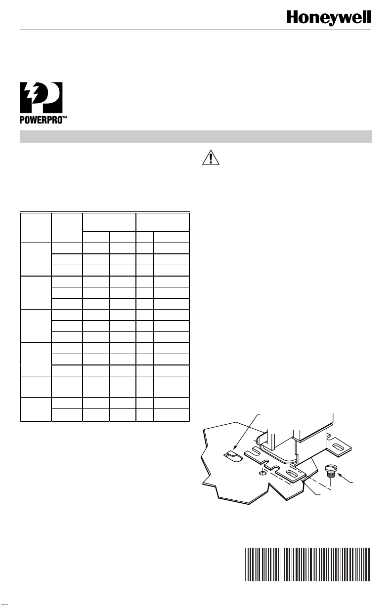
쐇 Use two screws to mount the contactor. Select
models use a shear formed panel tab to mount the
contactor. See Fig. 1.
쐋 See equipment manufacturer wiring instructions or
Fig. 2.
쐏 Attach the line wires to the contactor using terminal
clamp screws.
쐄 Attach the load wires using No. 10 binding screws.
쐂 Use pressure lugs for field wiring with wire larger
than No. 8.
SHEAR
FORMED TAB
INSTALLATION
When Installing this Product…
1. Read these instructions carefully. Failure to follow
them could damage the product or cause a hazardous condition.
2. Check the ratings given in the instructions and on
the product to make sure the product is suitable for
your application.
3. Installer must be a trained, experienced service
technician.
4. After installation is complete, check out product
operation as provided in these instructions.
Copyright © 1996 Honeywell Inc. • All Rights Reserved
Fig. 1. Typical contactor mounting.
X-XX UL
CONTACTOR
BASE
69-0874-3
SCREW
M5513
Page 2
DEFINITE PURPOSE (DP) CONTACTORS
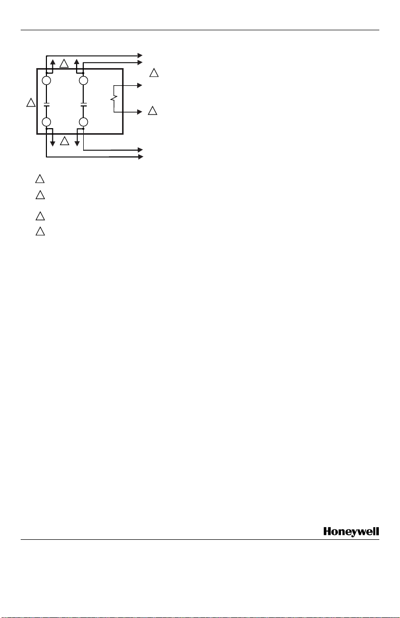
SINGLE
3
L1
4
POWER SUPPLY. PROVIDE OVERLOAD PROTECTION
1
AND DISCONNECT MEANS AS REQUIRED.
THE CONTROL CIRCUIT INCLUDES LINE VOLTAGE OR LOW
2
VOLTAGE POWER SUPPLY (DEPENDING ON MODEL USED),
CONTROLLER AND/OR SAFETY DEVICES.
QUICK-CONNECT TERMINALS FOR ACCESSORY
3
CONNECTIONS ONLY.
FOR REPLACEMENT OF SINGLE POLE CONTACTORS WITH
4
TRICKLE HEAT, A SUITABLY SIZED JUMPER WIRE SHOULD
BE PLACED BETWEEN L1 AND T1.
L2
T2T1
3
Fig. 2. Typical wiring diagram.
PHASE
POWER
1
TO
CONTROL
CIRCUIT
2
TO
CONTROLLED
LOAD
M8731A
Replacement Installation
쐃 Remove and identify contact and coil leads to
assure correct connection to the new contactor.
쐇 Remove the mounting screws from the old
contactor.
쐋 Mount the new contactor using the screws provided.
Some models include a 138550 Mounting Adapter
Plate for use when replacing competitive controls.
쐏 Reconnect the contact and coil leads to the proper
terminals.
CHECKOUT
Always conduct a thorough checkout when installation is
complete. Restore power supply and operate the contactor
and controlled equipment to assure the contactor pulls in
when the coil is energized and the controlled equipment
operates as intended.
Home and Building Control
Honeywell Inc.
1985 Douglas Drive North
Golden Valley, MN 55422
Home and Building Control
Honeywell Limited-Honeywell Limitée
155 Gordon Baker Road
North York, Ontario
M2H 2C9
69-0874—3 2
69-0874—3 J.S. Rev. 5-96 Printed in U.S.A
Helping You Control Your World
 Loading...