

Page 1

02/2011
Domonial CMI/CME
Installer’s manual 3
Manuel d’installateur 27
Page 2

Page 2 of 52
02/2011
Page 3

Page 3 of 52
02/2011
E
N
G
L
I
S
H
Contents
Introduction ............................................................................................. 5
Installation procedure .............................................................................. 7
Plan the installation ................................................................................. 8
Mount the panel .................................................................................... 10
Wire the panel ....................................................................................... 11
Register the TCU keypad ........................................................................ 12
Mount, register and programme devices ............................................... 13
Set the date and time............................................................................. 14
Save the configuration ........................................................................... 14
Test the installation ............................................................................... 15
Exit programming mode......................................................................... 16
Fit the panel cover ................................................................................. 16
Register a TAG ........................................................................................ 17
Test after arming the system ................................................................. 18
Specification .......................................................................................... 19
List of codes ........................................................................................... 21
Page 4

Page 4 of 52
02/2011
Page 5
Page 5 of 52
02/2011
E
N
G
L
I
S
H
Introduction
Domonial is a wireless control panel with a built-in siren, digital communicator and audio
verification system. The radio link between the various components of the system allows easy
installation with only a small amount of cabling (mains, and when specified, PSTN, X10 or a wired
intercom terminal). This version can be used with the HF and the M wireless device ranges, for
example DO800M.
After recording a wireless Audio device, all HF wireless device can not work your installation.
Domonial can be programmed using the following tools:
DOMOPC programming tool. Refer to the DOMOPC online help guide for full details.
A TCU keypad
This guide describes how to program the panel using a TCU keypad. A complete list of
programming codes is provided at the end of this manual.
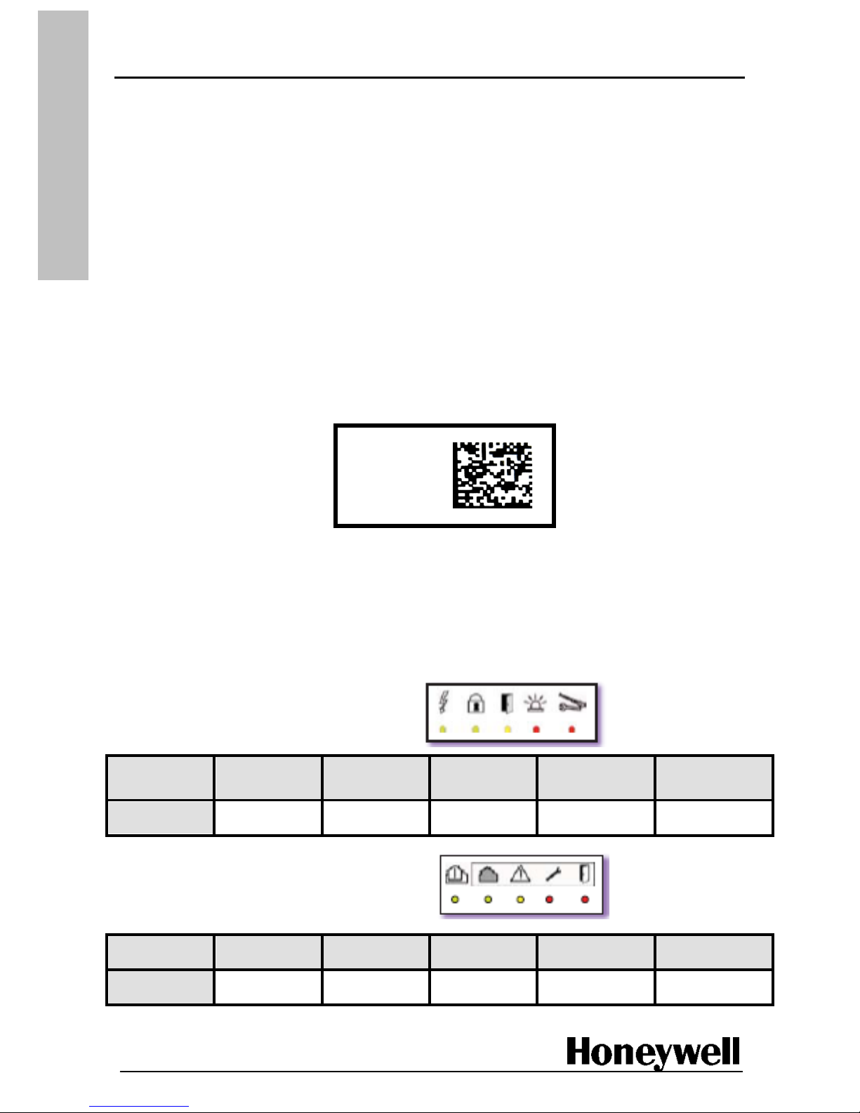
Panel Label
Commercial reference
Product file reference
Serial number Note: The format of
Date of manufacture date is yymmdd
The software version number is marked on a label on the box containing the panel (e.g. SW: L06) and
on a small label on the PCB.
The LED Indicators
The panel comes in two designs, depending on the version. Both designs have LED indicator lights
showing the status of the system.
LED latout for the classic version
State/LED
Mains Supply
Arm/Disarm
Perimeter
Fault
Intruder Alarm
Memory
Technical
Alarm Memory
Colour
Green
Green
Yellow
Red
Red
LED latout for the EN version
State/LED
Mains Supply
Fault Area
System Fault
Tamper Fault
Intruder Fault
Colour
Green
Green
Yellow
Red
Red
CMI8UK-STD-7
97AGC0B
75000C6C8
100320
Page 6
Page 6 of 52
02/2011
E
N
G
L
I
S
H
System operation
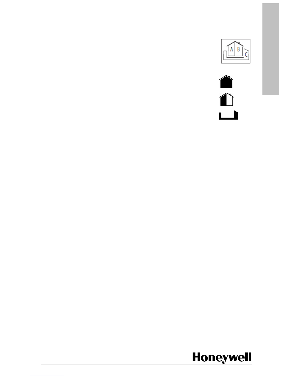
Once installed the Domonial alarm allows the surveillance of three different areas per site:
Area A = the perimeter or ground floor
Area B = the rest of the house
An optional Area C. The configuration of Area C depends upon the general
parameters “Annex arming linked to Total” and “Annex disarming linked
to Total”
Total set (all devices in the house – equivalent to Away in the UK)
Part set (a subset of the total set, usually installed as perimeter devices –
equivalent to Home in the UK)
Annex set (an additional set of devices, for example a second perimeter or
a garage – not generally used in the UK)
Arming and disarming
arming and disarming can be performed using:
Keypads and keyfobs, which can be associated with total or part sets, the annex set, or all
sets.
DTMF codes over the phone.
programming tools. This function is available depending on product version and country
regulations
Users
Keyfobs, keypads and codes, with which to access the alarm system, can be assigned to
a maximum of 10 users (including a master user). Each user can have a code and/or
a TAG for each keypad.
System operation by users can be detected, stored and reported to the monitoring station. In
addition, Domonial can be programmed to take a set of pictures when the system is armed or
disarmed that are sent to the monitoring station. Dedicated profiles for limited time access
and clocking are also available on some versions of the product.
Alarm detection
The access route devices can be set up as follows:
Immediate: direct trigger, a device is outside the access route
Delayed: with an entry/exit delay programmable from 0 to 90 seconds
(for total, part or annex areas)
Mixed: direct trigger or delayed if a delayed device was activated first.
Technical devices, such as a flood/temperature sensor, are permanently armed and trigger
independently of arming status.
Page 7

Page 7 of 52
02/2011
E
N
G
L
I
S
H
Alarm signalling
The following sounder operating modes can be programmed:
Standard siren
Siren activated after intrusion or after intrusion and PSTN failure
Siren activated on tamper detection only when system is armed or independent
of arming status
Siren activated on fire detection
Intruder siren duration can be programmed to a maximum of 4 minutes.
Activation of the sounder can also be postponed until after the alarm signal has been transmitted.
Fire siren duration is fixed to 5 minutes and can be delayed for up to 5 minutes.
Alarm transmission
Domonial is equipped with a digital transmitter for sending information via PSTN, optional
GSM/GPRS card, or optional Ethernet card to the following:
A telephone (PSTN, GSM voice)
An Alarm Receiving Centre using the following protocols: Secom3, Surtec, Cesa, Contact ID
Note: Data networks, such as GSM data or GPRS, use the SECOM3 protocol.
Installation procedure
The rest of this manual is designed to be followed in sequence and describes the following
main tasks:
Equipment siting (planning and installation)
Registration of wireless devices
Basic programming
Device and alarm testing
Contents of the box
Check that your Domonial box contains the following:
Domonial alarm panel, plus the User Manual
1 Stocko, four-pin connector inside the panel for the telephone connection
Breakout tabs for covering unused wire passages
A Velcro strap for securing the battery
A 4 V 3.5 Ah back-up battery is required, and is sold separately by Honeywell: part numbers
ELECKSON BPEL040035 or SONNENSCHEIN A504/3.5S.
Page 8

Page 8 of 52
02/2011
E
N
G
L
I
S
H
Plan the installation
To ensure the installation process is successful we recommend that you mark the position
of the system components on a drawing of the building.
A layout drawing is shown on the following page to help you plan the wiring into and out
of the panel.
Select positions for the panel and peripheral devices to maximise GSM signal level (if used),
audio coverage (if used), and wireless radio signal levels.
Note: Radio transmission is attenuated when sent through wood, Artex, brick, concrete, and steel
reinforcements. It is reflected by metal surfaces such as mirrors, steel sheeting, aluminium steamarrestor, and fine-mesh wire-netting.
Avoid these locations:
Metal objects, for example water tanks
230 VAC cables or consumer units
Close proximity to loud speakers
When used, the telephone line to the control panel must be as discrete as possible, and guarded
by a detector.
To ensure that alarm transmission takes priority over other telephone communications, always
position the panel after the exchange line and before all telephone extensions in the home.
If the site is equipped with an ADSL line, use a central ADSL filter after the exchange line
to separate telephone extensions and ADSL extensions.
For mains connection, the panel can be connected either via a socket outlet or directly to
a fused outlet.
Page 9
Page 9 of 52
02/2011
E
N
G
L
I
S
H
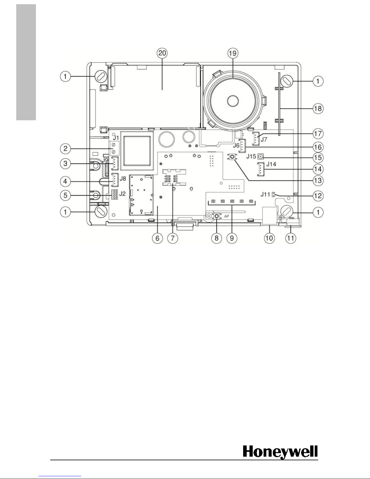
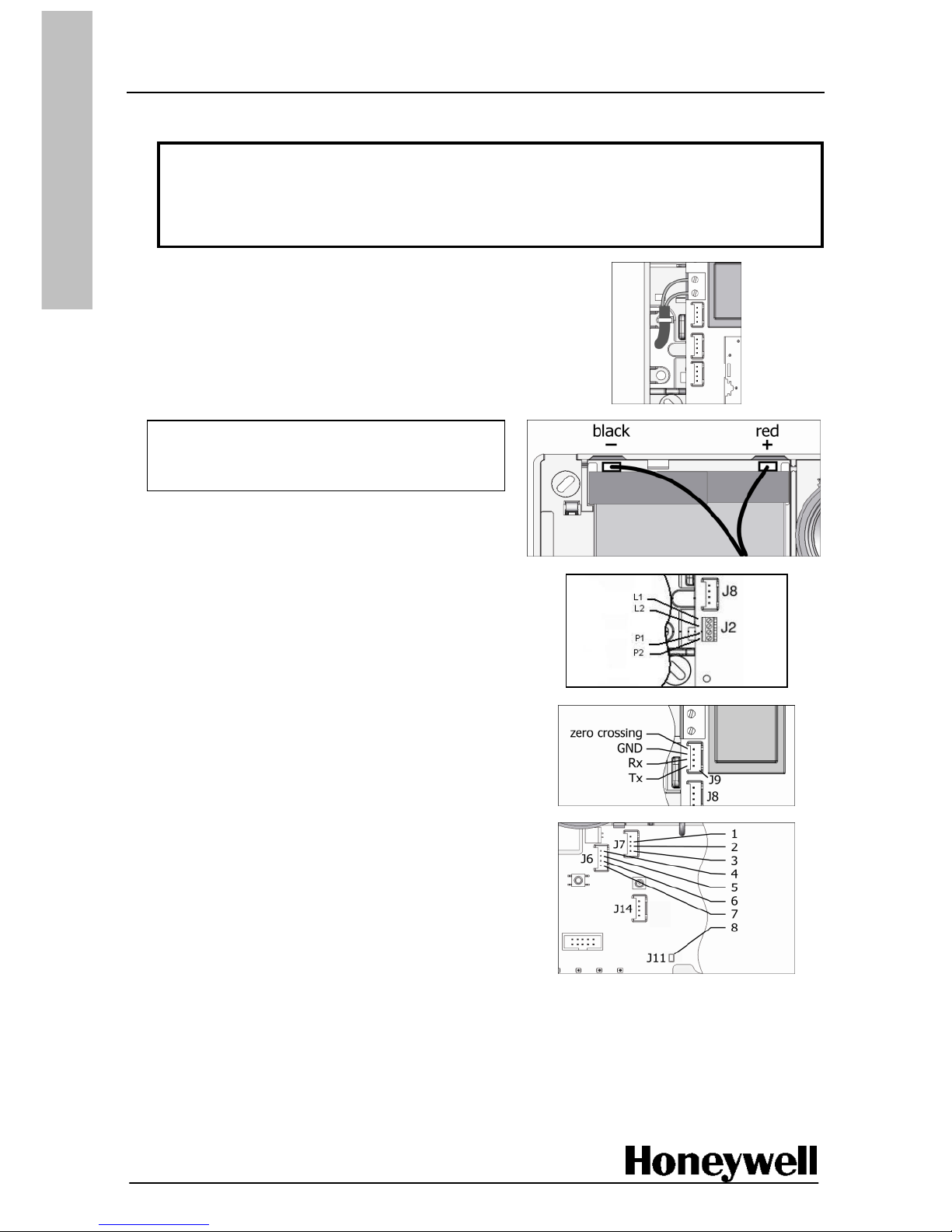
Panel internal layout and connections
1 mounting holes
2 mains connector (J1)
3 X10 connector (J9)
4 output voltage (J8)
5 PSTN connector (J2)
6 optional plug-in module, if fitted
(GSM/GPRS card shown)
7 SIM holder (GSM/GPRS module only)
8 tamper switch
9 status LEDs
10 RJ45 connector
11 microphone
12 external audio enable (J11)
13 call button
14 external antenna power (J14)
15 external antenna connector (J15)
16 external audio power and external
tamper connector (J6)
17 external audio connector (J7)
18 internal antenna
19 built-in speaker
20 battery compartment
Page 10
Page 10 of 52
02/2011
E
N
G
L
I
S
H
Mount the panel
Prior to starting the installation process call your alarm receiving centre (ARC) and ask them to
ignore any alarms during the installation and setup process.
WARNING: MOUNT THE PANEL SO THE BATTERY TERMINALS ARE AT THE
TOP. ANY OTHER ORIENTATION MAY RESULT IN LEAKS FROM THE BATTERY.
1. Remove the cover from control panel.
2. Hold the panel in its selected mounting position and mark the mounting hole locations, using
the panel as a template.
Note: Ensure the wall is flat enough to compress the tamper switch spring. Use fixings
adequate to support the weight of the panel and battery.
Caution: Do not drill holes with the panel in place.
3. Remove the panel from the wall and drill the mounting holes.
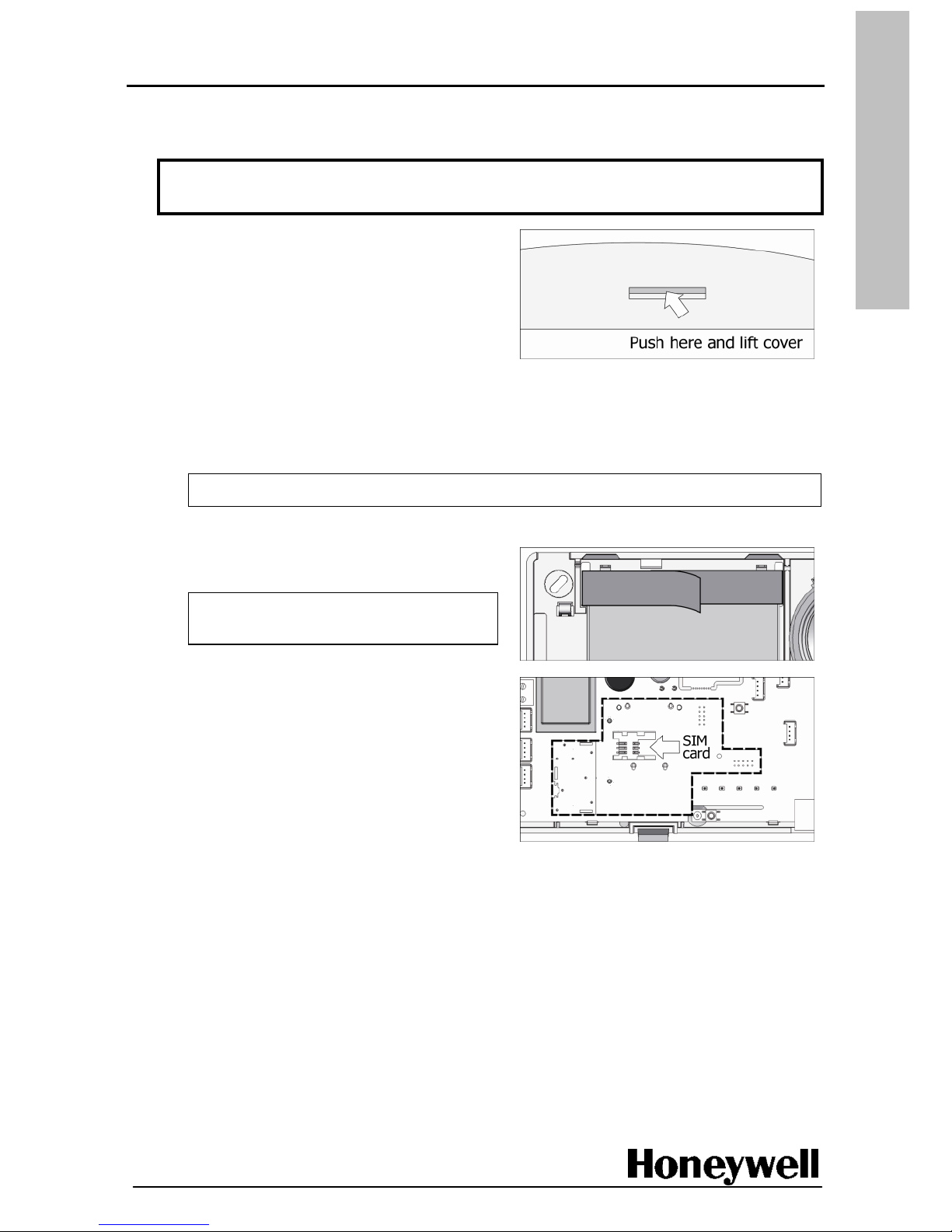
4. Insert the battery in the panel, and then
secure it with the Velcro strap as shown.
Caution: Do not connect the battery
until later.
5. If it is required, install a GSM/GPRS module
(shown), or Ethernet module, in the dashed
area on the drawing.
6. If using GSM communications, fit a SIM card
as shown.
7. Feed the mains and phone wiring through the base of panel, and screw the panel to the wall.
Page 11
Page 11 of 52
02/2011
E
N
G
L
I
S
H
Wire the panel
Mains wiring must be carried out in accordance with national and local regulations and guidelines.
WARNING: ANY ELECTRICAL WORK ON THE CONTROL PANEL MUST BE
CARRIED OUT BY QUALIFIED PERSONNEL.
CAUTION: DO NOT LEAVE THE BATTERY CONNECTED TO THE CONTROL
PANEL WITHOUT MAINS POWER.
1. Using 2 x 0.75 mm
2
flexible cable or 2 x 1 mm2
rigid wire, connect the mains wiring and
secure it in place with a cable tie.
Use the second tie point if you route the cable
vertically down and out of the panel.
Caution: To prevent equipment failure,
connect the battery wires to the correct
terminals on the battery.
2. Connect the battery wires.
3. If required, connect a PSTN cable using
the 4-pin Stocko connector.
4. If required, connect an X10 device as shown.
5. If required, connect a remote intercom
terminal (TP800) as shown and described
below. Ensure that jumper J11 (8) is fitted.
J7 connector J6 connector
1 CMD 4 external tamper
2 microphone 5 external tamper
3 speaker 6 − audio power
7 + audio power
6. Switch on the mains supply to the panel.
Follow the next procedure to register the TCU
keypad
Page 12
Page 12 of 52
02/2011
E
N
G
L
I
S
H
Register the TCU keypad
Refer to the TCU installation instructions before starting this part of the process. Register the TCU
near to the panel so you can hear the audible feedback.
Note: If programming takes longer than 1 hour, replace the TCU battery before handing over
to the end user.
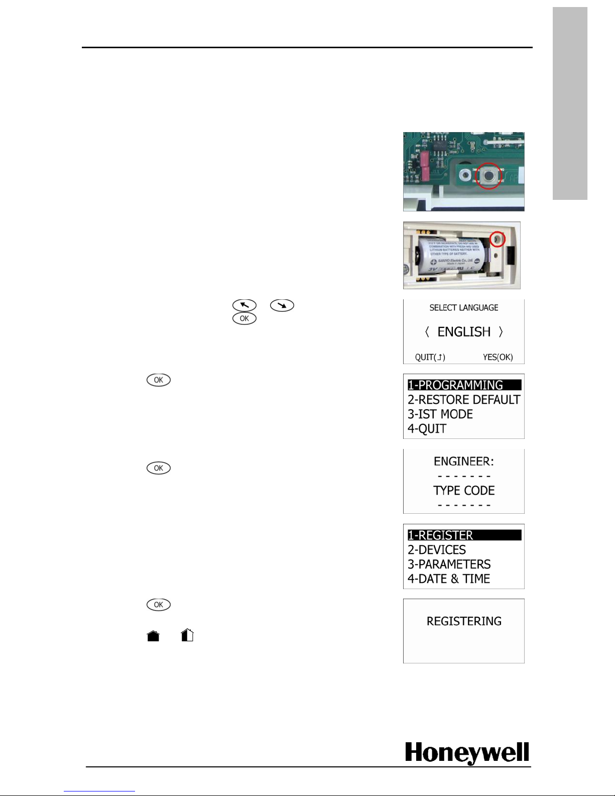
1. Press the tamper switch on the panel until you hear a click,
and then hold for 3 seconds. This places the panel in
programming mode.
2. Insert the battery into the TCU keypad.
3. Press P, the programming switch on the TCU keypad. The
panel will sound an audible beep if registration has been
successful. Replace the battery cover.
4. On the TCU keypad press or
to select your
language, and then press . The four main menu
options are displayed.
5. Press
to select the PROGRAMMING option.
The ENGINEER: TYPE CODE screen is displayed.
6. Using the keypad, type the engineer code, and then
press . By default the REGISTER option is highlighted.
Note: The code can be found in the list of codes (table
10-Access Codes) at the end of this manual.
Note: If you re-enter programming mode using a registered
TCU keypad, omit the following steps and start modifying
or adding devices.
7. Press to select REGISTER. The word REGISTERING is
displayed on the screen.
8. Press and together. The panel will sound an audible
beep if registration has been successful, and the VIEW
DEVICE screen is displayed.
9. Follow the next procedure to add devices to your system.
Page 13
Page 13 of 52
02/2011
E
N
G
L
I
S
H
Mount, register and programme devices
Take each wireless device in turn to its mounting position, together with the TCU, and then carry
out the following procedure for each one.
1. Mount the device according to the device's documentation. Do not add the battery
at this time.
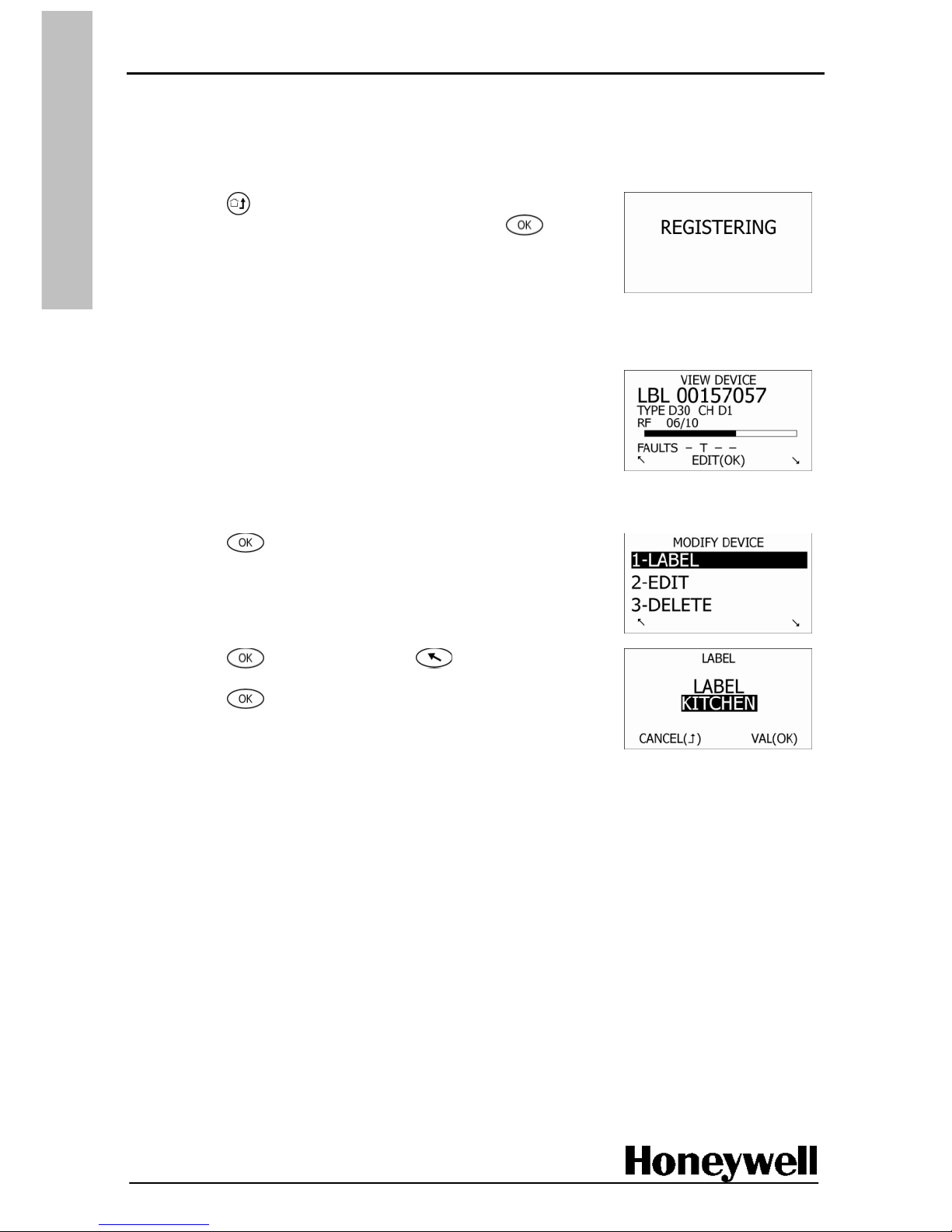
2. Press
twice to return to the programming submenu,
ensure REGISTER is highlighted, and then press .
The word REGISTERING is displayed on the screen.
3. Insert the battery in the device, according to the device instructions.
4. Press the tamper on the device (check the device
instructions, some devices may not have a tamper). The
serial number, type and radio level are displayed on the TCU.
5. Check the radio level. It should be greater than 3 for devices,
and greater than 4 for audio wireless devices.
6. Place the cover on the device, or place the device on its
socket (refer to the device instructions).
7. Press to display the MODIFY DEVICE menu. Although it
is optional, we recommend you complete the next step and
apply a meaningful label to the device.
8. Press to select LABEL. Press several times to
remove the default label, type a new label, and then
press .
This completes the basic registration of a device, however you can also set the following:
On the MODIFY DEVICE menu, select EDIT to change the device default settings to meet your
system's particular requirements. A list of codes is provided at the end of this manual.
On the MODIFY DEVICE menu, select CHANNEL to change the channel number. This is not
recommended unless specified by your alarm service supplier. By default, channel numbers
are assigned automatically when a device is registered.
Repeat this procedure, as necessary, for all devices in the system.
Page 14
Page 14 of 52
02/2011
E
N
G
L
I
S
H
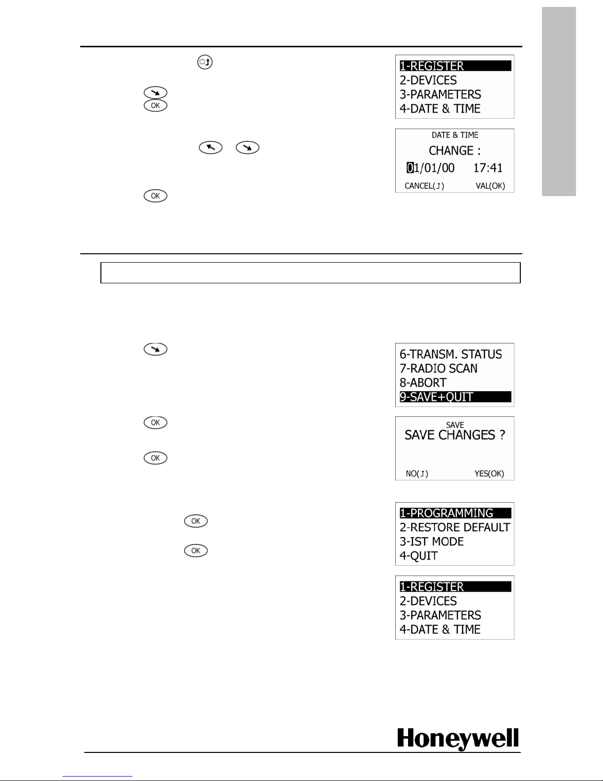
Set the date and time
1. On the TCU, press
twice to return to the programming
submenu.
2. Press
until DATE & TIME is highlighted, and then
press .
3. Enter the date and then the time using the keypad.
If necessary, press or
to scroll left or
right and make changes.
Note: The date format is language dependent.
4. Press
to save your settings.
Save the configuration
Caution: Do not forget to save your configuration!!
Note: If all the panel LEDs light in succession after saving a configuration, one or more parameters
has been set with an incorrect value. Installation cannot be completed until the values
are corrected.
1. Press several times to highlight SAVE+QUIT.
2. Press .
The SAVE CHANGES message is displayed?.
3. Press .
A PLEASE WAIT message is displayed for a few seconds
before main menu is finally displayed.
4. On the main menu, ensure PROGRAMMING is highlighted,
and then press .
5. Using the keypad, type the engineer code,
and then press .
The programming options are then displayed.
Follow the next procedure to test the installation.
Page 15
Page 15 of 52
02/2011
E
N
G
L
I
S
H
Test the installation
Use this procedure to make sure the system is programmed and working correctly.
Panel test
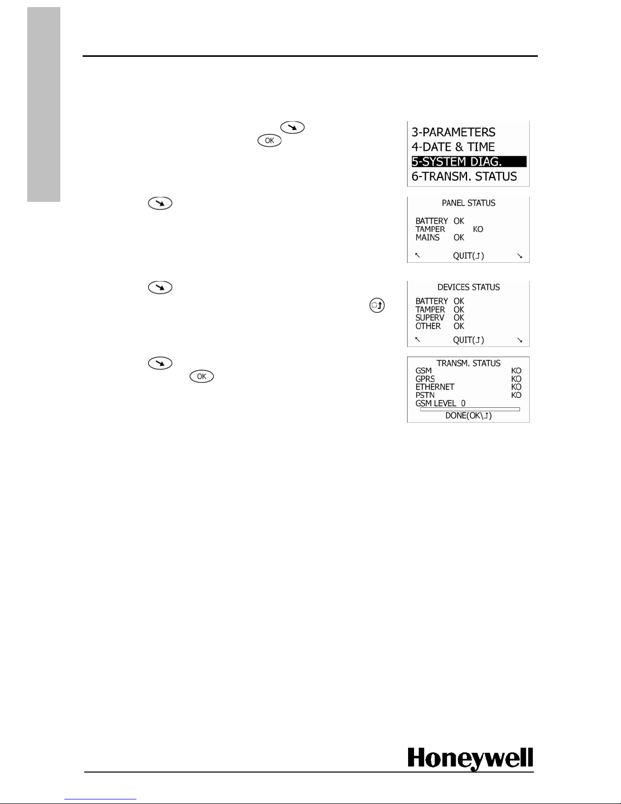
1. On the programming submenu, use to highlight
SYSTEM DIAG., and then press .
The PANEL VERSION screen is displayed.
2. Press to display the PANEL STATUS screen.
3. Check that OK appears next to each line.
Note: Tamper will remain as KO until the panel cover is
replaced. If you press and hold the panel tamper switch,
KO will change to OK.
4. Press
to display the DEVICES STATUS screen.
5. Check that OK appears next to each line, and then press
to return to the programming submenu.
6. Press
to highlight TRANSM. STATUS,
and then press .
7. Check that OK appears next to any installed communication
devices. If a GSM card is installed check that the level is
greater than 15.
Page 16
Page 16 of 52
02/2011
E
N
G
L
I
S
H
Device communication test
Apply this test to make sure each wireless device communicates with the panel when
it is activated (triggered).
Note: Alarm testing is carried out later.
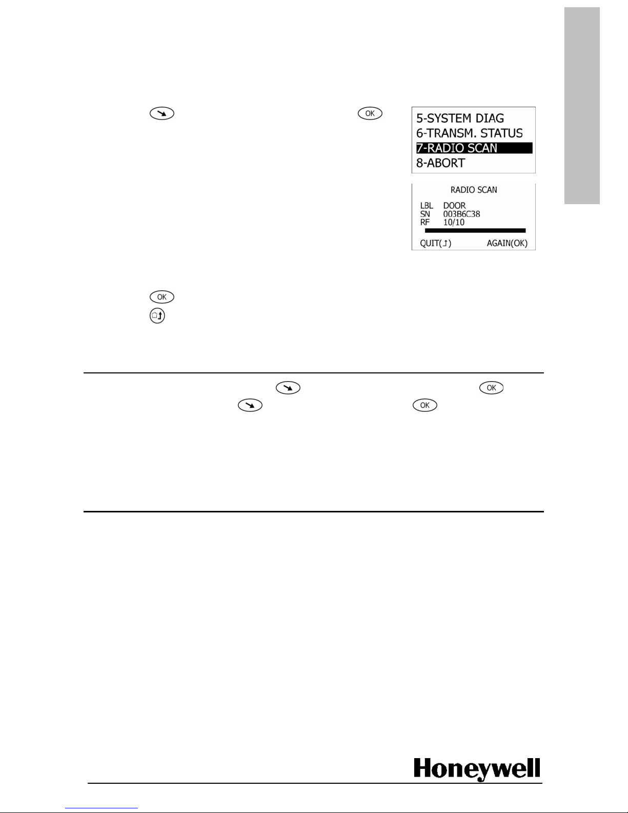
1. Press to highlight RADIO SCAN, and then press .
WAITING FOR RECEPTION is displayed on the screen.
2. Activate a device (to activate a smoke detector use an
approved testing product). The radio scan test screen
is displayed.
3. Check that there is an RF signal level for the device being tested. It should be greater than
3 for devices, and greater than 4 for audio wireless devices.
4. Press , and repeat the procedure from step 2. until all devices have been activated.
5. Press to quit the test.
Exit programming mode
1. On the programming menu, press to highlight SAVE+QUIT, and then press .
2. On the main menu, press to highlight QUIT, and then press to leave programming
mode.
3. Wait until the TCU screen goes blank.
The TCU is now in User Mode.
Fit the panel cover
When you have installed and tested all of the devices, fit the appropriate blanking plugs to the
panel cover, and then fit the cover to the panel base.
Page 17

Page 17 of 52
02/2011
E
N
G
L
I
S
H
Register a TAG
To meet the requirements of EN50131-1 a TAG must be used to arm and disarm the system.
Therefore, it may be necessary to register a TAG during the installation process.
Note: We recommend you register a TAG and always use it to arm and disarm the system, even if
it is not a mandatory requirement.
1. On the TCU, press
to wake up the keypad, and then press
again to
highlight USERS.
2. Press , to access the USERS screen.
3. Press
to highlight TAGS, and then press . The
USER ACCESS screen is displayed.
4. Enter the 6-digit Master User Code. The TAGS screen is
displayed, with M (the master user) highlighted.
5. Press
to display the TAGS ALLOWED ? message.
6. Press to display the PRESENT TAG message.
7. Place your master TAG close to the TCU keypad TAG reader
(between, and below the and buttons).
The ACCEPT NEW TAG message is displayed?
8. Press to accept the new TAG.
9. The TAG is now registered and can be used to arm and disarm the system.
Page 18

Page 18 of 52
02/2011
E
N
G
L
I
S
H
Test after arming the system
Although use of a TCU keypad is described here, you can use any Domonial keypad to perform
this test. The and icons vary slightly from one keypad to another.
Generate alarm events
1. Place the TCU keypad in its base.
Note: You cannot arm the Total Set without doing this.
2. On the keypad, press , the Part Set arm button. The PRESENT TAG message is displayed.
3. Place your master TAG close to the keypad TAG reader. The arming process starts to count
down from 60s. At the end of this time the PART SET IS NOW ARMED message is displayed.
4. Activate a device (the alarm will sound).
Note: It is unnecessary to test smoke detectors a second time.
5. Place the TAG to the keypad to disarm the system and cancel the alarm.
6. Reset the device.
7. Repeat the test from step 2 and test the next device. Continue testing until all devices in the
Part Set have been tested.
Repeat the whole process for the remaining devices in the system. To do this, press in step 2.
to arm the Total Set.
View the alarm events
1. Ensure the TCU screen is blank. If not, press .
2. Press or
to display the user menu.
3. Press or
to highlight the EVENTS menu option,
and then press . The latest event is displayed.
4. Press
to scroll back through the events and make sure all the alarms you generated
have been recorded.
5. Press
to quit the EVENTS screen.
6. Call your alarm receiving centre (ARC) to verify that they have received the alarm signals.
This concludes the installation. After providing training to the end user, call the ARC and ask them
to start monitoring the installation.
Page 19

Page 19 of 52
02/2011
E
N
G
L
I
S
H
Specification
Features
3 protected sets (Total, Part, Annex)
Management of wireless peripherals of the Domonial 800 range (HF and M)
Digital transmission format : Secom3, Cesa, Surtec, contact ID
Other format : phone
Built-in and/or external audio half-duplex system
Built-in capability to support wireless audio
8 phone numbers / 6 call cycles
Events log for 1000 events
Built-in siren
Panel tamper on opened cover or off the mounting set-up
Remote parameter feeding from PC and Domodem-GSM; locally from computer
Physical
MTBF
20 years
Dimensions
Height: 183 mm
Width: 235 mm / 295 mm depending on cover
Max depth: 50 mm / 56 mm
Temperature
(EN50130-1 Standard)
Operating: −10°C to +55°C
Storage: −40°C to +70°C
Relative humidity
< 85%
Weight (with battery)
1280 g (2.8 lbs)
Page 20

Page 20 of 52
02/2011
E
N
G
L
I
S
H
Electrical
Power supply
Ut: 230 V~ 50 Hz, 35 mA (typical)
Mains current at Ut
module not fitted
with GPRS module
Normal: 54 mA
66 mA (Idle)
Calling: 127 mA
202 mA (GSM)
312 mA (GPRS)
Battery
Type: 4 V 3.5 Ah max
Fault: when battery voltage < 3.85 V (fault is reset after
20 minutes of charging)
Battery Life: 40 Hrs (with GSM/GPRS module)
Voltage output
(for audio terminal)
4 V +/− 5%, 300 mA max.
250 mA ripple
Radio
Radio frequency
868 MHz (FM narrow band)
Number of channels
Total: 32
Sensors: 30
Keyfobs: 10
Keypads: 4
Sirens: 4 (indoor and outdoor)
Standard* CAMIR/CAMIR-N: 10
IRVPI800M: 5
External trigger** CAMIR/CAMIR-N: 5
Radio jamming detection
Detection of transmission in the band for more than 30s over a
period of 60s
* Taking pictures upon intrusion alarm
** Taking pictures upon intrusion alarm + capability of accepting a trigger signal to take a picture
Page 21

Page 21 of 52
02/2011
E
N
G
L
I
S
H
List of codes
Devices
1-RF Sensors (type D): DO800M, DODT800M, DF8M, DET8M, IR8M, IRPI8M, DFO800M,
CAMIR, CAMIR-N, IRVPI800M
Parameter
Short
Addr.
Long
Address
Values
Defaults
Partition
101
1323
0 = Total
1 = Partial Set
2 = Annex
3 = 24/24
D0800M = 1
IR8M = 0
IRPI8M = 0
Trigger condition
102
1425
0 = Immediate
1 = Delayed
2 = Mixed
3 = Exit door*
D0800M = 3
IR8M = 0
IRPI8M = 0
Function
103
1527
0 = Intrusion
1 = Technical
2 = Pre-alarm
3 = Perimeter
5 = Fire
6 = Driver
0
Chime
104
19 429
0 = Inactive
1 = Active
0
Transmission
111
2120
0 = OFF
1 = Alarm/End
2 = Alarm
Channels 1 – 10 = 2
Channels 17 – 18 = 1
Alarm code
(1st protocol)
112
2646
3 digits
Channels 1 – 10 = 130
Channels 17 – 18 = 110
End alarm code
(1st protocol)
113
2748
3 digits
Channels 1 – 10 = 130
Channels 17 – 18 = 110
Frequently used sensor
105
19 728
0 = Disabled
1 = Enabled
0
* software version K only
2-RF LCD Keypad (Type K16): TCU (all versions)
Partition
201
18 128
0 = Total
2 = Annex
3 = Total + Annex
0
Alert button
202
18 221
0 = Inactive
13 = Alert 1
14 = Alert 2
15 = Alert 3
0
3-RF LED Keypads (Type K5 and K9) CLI810HF and CSK800HF-B
Partition
301
1323
0 = Total
2 = Annex
3 = Total + Annex
0
Alert button
302
1425
0 = Inactive
1 = Alert 1
2 = Alert 2
3 = Alert 3
4 = Chime
1
Page 22

Page 22 of 52
02/2011
E
N
G
L
I
S
H
4-RF Keyfob 800M range (type F31): TCB800M, TCB8M, TCBPA8M, TCC800M, TCC8M
User
403
1323
User 1 (Master) = 0, User 2 = 1, User 3 = 2, ..User 10 = 9
0
Zone
401
19 120
0 = Total (Annex inhibited)
2 = Annex
3 = Total + Annex
3
Alert
402
19 223
0 = Inactive
1 = Alert 1
2 = Alert 2
3 = Alert 3
0
Control (key #4)
411
19 326
0 = NO FUNCTION
1 = Arm total set
2 = Disarm total & partial sets
3 = Arm partial set
4 = Arm annex set
5 = Disarm annex set
6 = Drive Receiver 1
7 = Drive Receiver 2
8 = Drive Receiver 3
9 = Drive Receiver 4
10 = Drive Receiver 5
11 = Drive Wired Output
13 = Alert 1
14 = Alert 2
15 = Alert 3
0
Control + Arm (4 + 1)
412
19 429
4
Control + Disarm (4 + 2)
413
19 522
5
Control + Part arm (4 + 3)
414
19 625
0
4-RF Keyfob 800HF range (type F): TC805HF
User
403
1323
User 1 (Master) = 0, User 2 = 1,
User 3 = 2, … User 10 = 9.
0
Function
415
1425
According to the following table
10
(On/Off_T/P/RS/Alert 1)
Associated receiver
416
1629
0 to 34. 255 for None.
Function/Key 1 2 3 4
1+3
0
Arm total set
Disarm all
Arm Partial set
Alert 3
No effect
1
Arm annex set
Unset annex
2
Arm Partial set
Alert 1
3 to 5
Arm Partial set
Receiver
Alert 1 to 3
6 to 8
Arm annex set
Receiver
Alert 1 to 3
9
Arm Partial set
Alert 1
Alert 3
10 to 12
Disarm total & part
sets
Arm Partial set
Receiver
Alert 1 to 3
13
Arm Partial set
Alert 2
Alert 1
Page 23

Page 23 of 52
02/2011
E
N
G
L
I
S
H
5-Built-in panel sounders (type A26)
Beep level
511
13 128
0 to 7
0 = Disabled
7 = Maximum
4
Intruder siren level
521
13 221
0 to 8
0 = Disabled
7 = Maximum
8 = Progressive
8
Intruder siren duration
522
0293 225
0 to 240 seconds * 5 (enter 900 for 180 seconds)
180 secs
Intruder siren delay
523
0293 120
0 to 240 seconds * 5 (enter 150 for 30 seconds)
0 secs
Fire siren level
531
13 324
0 to 7
0 = Disabled
7 = Maximum
6
6-RF sounders (types A6 and A7): SI800HF, SI800M, SEF800HF, SEF2-800HF, SEF8M
Intruder siren duration
622
0293 225
0 to 240 seconds * 5 (enter 900 for 180 seconds)
180 secs
Intruder siren delay
623
0293 120
0 to 240 seconds * 5 (enter 150 for 30 seconds)
0 secs
Intruder siren level
621
13 221
1 to 8
7 = Maximum
8 = Progressive
8
Note: Software < K19: 0 to 240 seconds * 5 (enter 900 for 180 seconds, enter 150 for 30 seconds)
General Parameters Type G
Note: Default values are in the last column.
10-Access Codes
Engineer code
1001
023 127
6 digits
001234
User Code length
1011
023 523
4 or 6 digits
6 digits
Arming without code
1021
02015 123
0 = Allowed
1 = Password required
1
TCU keyfob mode
1022
02015 229
0 = Not supported
1 = Supported
0
20-User attributes
User Name
8 characters maximum
(only letters and figures – no special characters).
User 1 = “M”
User 2 … 10 = “2”…”10”
User Profile
1 = Standard
4 = Supervised
1
#
User name
User Profile
#
User name
User Profile
1
2001
81 117
2011
81 01121
6
2006
86 117
2016
86 01121
2
2002
82 119
2012
82 01123
7
2007
87 119
2017
87 01123
3
2003
83 111
2013
83 01125
8
2008
88 111
2018
88 01125
4
2004
84 113
2014
84 01127
9
2009
89 113
2019
89 01127
5
2005
85 115
2015
85 01129
10
2010
8010 112
2020
8010 01120
Page 24

Page 24 of 52
02/2011
E
N
G
L
I
S
H
30-Arming and disarming
All delays are expressed in seconds.
Total Set
Partial Set
Annex Set
All Sets
Entry delay
3013
331 126
3113
341 128
3213
024 231 128
30 secs
Entry beeps
3012
331 220
3112
341 222
3212
024 231 225
30 secs
Exit delay
3023
332 223
3123
342 121
3223
024 232 221
60 secs
Exit beeps
3022
332 327
3122
342 225
3222
024 232 328
56 secs
Delay behaviour is determined by the following attributes:
Annex linked to total on arming
3301
024 328
0 = Independent
1 = Armed with total
0
Annex linked to total on disarming*
3302
024 922
0 = Independent
1 = Disarmed with total
0
Arm if perimeter open
3303
0251 120
0 = Allowed
1 = Forbidden
0
* Software version I12 or higher
40-Audio signals
Chime
4001
02532 621
0 = Disabled
1 = Enabled
1
50-Alarm Confirmation
Alarm Confirmation
5001
0252 324
0 = No
1 = Yes
0
51-Restoring
To perform an engineer reset, type in code 0258 152 199, then enter extra parameter 0.
Tamper reset
5101
0251 320
0 = Automatic, 1 = By Engineer
0
Reset with anticode (system lock)
5102
02301 0121
Enabled = 1, Disabled = 0
0
Algorithm key for anticode
5103
02301 0325
0 to 255
0
70-Transmission
Transmitter
7001
1129
0 = Inactive
1 = PSTN
2 = GSM/Ethernet Module
3 = PSTN+GSM/Ethernet Module
0
PSTN Prefix
7103
13146
Up to 17 characters (“+” should be replaced by “00”)
-
GSM PIN Code
7204
14148
4 digits
0000
APN #1
7211
14415
Up to 30 characters
-
APN #1 Login
7212
14518
Up to 20 characters
- APN #1 Password
7213
14611
Up to 20 characters
- APN #2
7221
14817
Up to 30 characters
- APN #2 Login
7222
14910
Up to 20 characters
-
APN #2 Password
7223
140 1019
Up to 20 characters
-
Alarm sent if Partial set
7002
025 529
0 = not sent
1 = sent
0
Page 25

Page 25 of 52
02/2011
E
N
G
L
I
S
H
74-Digital protocols
First protocol
7411
51 128
5 = SECOM3
7 = VOCAL
9 = CONTACT ID
9
First subscriber number
7412
51 249
Up to 8 hexadecimal digits
(e.g. 0000XXXX for 4-digit numbers)
00009999
75-Telephone numbers
For each phone number, it is possible to select the network, address number or IP address, plus supported protocol,
with the following constraints:
The telephone number parameters only apply to PSTN, GSM Voice and GSM data.
The IP Address parameters only apply to GPRS and Ethernet.
Number
At most 21 characters
(including * ; , and #. + should be replaced by 00)
-
IP address: port number
The IP address consists of 4 groups of 3 digits (e.g. xxx.xxx.xxx.xxx:yyy).
-
Selected APN
0 = First
1 = Second
G = 0, H = 1
The address codes for telephone numbers A to H are according to the following table.
A B C D E F PSTN
PSTN
PSTN
PSTN
GSM
GSM DATA
Number
7511
61 240
7521
62 242
7531
63 244
7541
64 246
7551
65 248
7561
66 240 G
H
GPRS
GPRS
IP address
7572
67 238
7582
68 230
Selected APN
7573
67 420
7583
68 422
76-Cyclic Tests
Test 1 period
7611
41 127
0 to 44639 in minutes (24h = 1440 min)
-
Test 1 start hour
7612
41 426
0 to 23 -
Test 1 start minute
7613
41 529
0 to 59 -
77-Incoming Calls
Pick up line
7701
15 328
0 = Never
1 = After n rings
2 = Double call
1
Number of rings
7702
15 122
2 to 12 8
Call in maintenance
7703
15 823
0 = authorised
1 = locked
0
6-Receivers (Types A25 and A27): Wired panel output or X10 address
Activate wired extension
610
03314111397
1B 0 10000002
-
Activate X10 address
620
03314111397
19 0 HHUU
HH: 2-digit number for “house” letter (00 for A)
UU: “unit” number minus 1 (00 for 1, 0A for 11)
0000
This should also be followed by the advanced command: type in parameter address 0297093 and validate
Page 26

Page 27

Page 27 sur 52
02/2011
F
R
A
N
C
A
I
S
Sommaire
Introduction ........................................................................................... 28
Procédure d’installation ......................................................................... 30
Planification de l’installation ................................................................. 31
Montage de la centrale .......................................................................... 33
Câblage de la centrale ............................................................................ 34
Enregistrement du clavier TCU ............................................................... 35
Montage, enregistrement et programmation de périphériques ............ 36
Réglage de la date et de l’heure ............................................................. 37
Enregistrement de la configuration ........................................................ 37
Test de l’installation ............................................................................... 38
Fermeture du mode programmation ..................................................... 39
Installation du capot de la centrale ........................................................ 39
Enregistrement d’un badge .................................................................... 40
Test après armement du système .......................................................... 41
Spécifications ......................................................................................... 42
Liste des codes ....................................................................................... 44
Page 28

Page 28 sur 52
02/2011
F
R
A
N
C
A
I
S
Introduction
Domonial est une centrale sans fil intégrant une sirène, un dispositif de communication numérique
et un système de vérification audio. La liaison radio entre les différents composants du système
facilite son installation et limite le câblage utilisé (secteur et, lorsque spécifié, PSTN, X10 ou terminal
d’interphonie câblé). Cette version est compatible avec les gammes de périphériques sans fil HF et
M, par exemple le DO800M.
Dés l’enregistrement d’un périphérique Audio sans sil, l’ensemble des périphériques sans fil HF ne
peuvent plus fonctionner sur ce système.
La centrale Domonial peut être programmée à l’aide des outils suivants :
Outil de programmation DOMOPC. Consultez l’aide en ligne de DOMOPC pour plus
d’informations.
Clavier TCU
Ce guide vous explique comment programmer la centrale à l’aide du clavier TCU. Une liste
complète des codes de programmation est fournie à la fin de ce manuel.
Panel Label
Référence commerciale
Référence dossier produit
Numéro de série Remarque: le format
Date de fabrication de la date aammjj
Le numéro de version du logiciel est indiqué sur une étiquette apposée sur l’emballage de la centrale
(par ex. SW : L06), ainsi que sur une petite étiquette collée sur la carte du PCB.
Voyants LED
Suivant la version, la centrale Domonial existe en deux modèles, équipés chacun de voyants LED
indiquant l’état du système
Disposition des voyants LEDS dans la version classique
État/Led
Alimentation
secteur
Marche/Arrêt
Défaut
périmètre
Mémoire alarme
intrusion
Mémoire alarme
technique
Couleur
Vert
Vert
Jaune
Rouge
Rouge
Disposition des voyants LED dans la version EN
État/LED
Marche/Arrêt
Défaut zone
Défaut
système
Défaut
Autoprotection
Défaut intrusion
Couleur
Vert
Vert
Jaune
Rouge
Rouge
CMI8FR-STD-7
97AGC0B
75000C6C8
100320
Page 29

Page 29 sur 52
02/2011
F
R
A
N
C
A
I
S
Fonctionnement du système
Une fois installé, le système d’alarme Domonial peut assurer la surveillance de trois zones
distinctes par site :
Zone A = la périmétrie ou le rez-de-chaussée
Zone B = le reste de la maison
Une zone C en option : La configuration de la Zone C dépend des
paramètres « Marche Annexe liée à Totale » et « Arrêt Annexe
liée à Totale »
Surveillance de la zone principale (Mode Total) = Les zones A + B sont
protégées, l’utilisateur n’est plus sur le site
Surveillance partielle (Mode Partiel) = Seule la zone A est protégée,
l’utilisateur est présent sur le site
En option : Surveillance totale (Mode Totale + Annexe) = Toutes les zones
sont protégées, l’utilisateur n’est pas présent sur le site
Armement et désarmement
Le système peut être armé et désarmé à l’aide des éléments suivants :
Claviers et porte-clés, qui peuvent être associés aux ensembles total, partiel ou annexe, voire
à tous les ensembles.
Codes DTMF sur liaison téléphonique.
Outils de programmation. Cette fonction est disponible selon la version de produit et les
réglementations nationales.
Utilisateurs
Les porte-clés, les claviers et les codes, qui permettent d’accéder au système d’alarme, peuvent
être affectés à dix utilisateurs maximum (dont un utilisateur principal). Chaque utilisateur peut
disposer d’un code et/ou d’un badge pour chaque clavier.
Les opérations exécutées par les utilisateurs sur le système peuvent être détectées, stockées et
signalées au poste de surveillance. De plus, le système Domonial peut être programmé pour
prendre un jeu de photos qui seront transmises au poste de surveillance, et ce qu’il soit armé ou
désarmé. Des profils dédiés d’accès et de pointage pour une durée limitée sont également
disponibles sur certaines versions du produit.
Détection des alarmes
Les périphériques du périmètre d’accès peuvent être configurés comme suit :
Immédiat : déclenchement direct, périphérique hors du périmètre d’accès.
Différé : avec délai d’entrée/de sortie programmable entre 0 et 90 secondes (pour les zones
totales, partielles ou annexes).
Mixte : déclenchement direct ou retardé en cas d’activation d’un périphérique différé en
premier lieu.
Les périphériques techniques tels que les capteurs d’inondation/de température sont armés en
toutes circonstances et se déclenchent indépendamment du statut de l’armement.
Page 30

Page 30 sur 52
02/2011
F
R
A
N
C
A
I
S
Signaux d’alarmes
La signalisation sonore peut être programmée conformément aux modes de fonctionnement
suivants :
Sirène standard
Sirène activée après une intrusion ou après une intrusion et une défaillance du RTPC
Sirène activée sur détection d’un sabotage, uniquement lorsque le système est armé ou
indépendant de l’état d’armement
Sirène activée sur détection d’un incendie
La durée d’activation de la sirène anti-intrusion peut être programmée sur 4 minutes maximum.
L’activation de La signalisation sonore peut également être différée jusqu’à ce que le
signal d’alarme ait été transmis.
La durée d’activation de la sirène incendie est fixe (5 minutes) et peut être différée de 5 minutes
maximum.
Transmission des alarmes
Le système Domonial est équipé d’un émetteur numérique permettant d’envoyer des
informations via RTPC, une carte GSM/GPRS optionnelle ou une carte Ethernet optionnelle :
à un téléphone (RTPC, voix GSM)
à un centre de réception d’alarmes à l’aide des protocoles suivants : Secom3, Surtec, Cesa,
Contact ID.
Remarque : les réseaux de données tels que les réseaux GSM ou GPRS utilisent
le protocole SECOM3.
Procédure d’installation
Le reste de ce manuel décrit les tâches suivantes qui doivent être réalisées dans l’ordre indiqué :
Implantation des équipements (planification et installation)
Enregistrement des périphériques sans fil
Programmation de base
Test des périphériques et des alarmes
Contenu de l’emballage
Vérifiez que l’emballage du système Domonial contient bien les éléments suivants :
Centrale d’alarme Domonial et manuel d’utilisation
Caches amovibles pour masquer les entrées de câble non utilisées
Bande Velcro pour maintenir la batterie
Une batterie de secours de 4 V 3,5 Ah est requise. Elle est vendue séparément par Honeywell :
référence ELECKSON BPEL040035 ou SONNENSCHEIN A504/3.5S.
Page 31

Page 31 sur 52
02/2011
F
R
A
N
C
A
I
S
Planification de l’installation
Pour vous assurer du bon déroulement du processus d’installation, nous vous recommandons
d’indiquer l’emplacement des composants du système sur un plan du bâtiment.
Un schéma de disposition est fourni sur la page suivante pour vous permettre de planifier le
câblage entrant et sortant de la centrale.
Positionnez la centrale et les périphériques afin d’optimiser le niveau de signal GSM (le cas
échéant), la couverture audio (le cas échéant) et les niveaux de signal radio sans fil.
Remarque : les transmissions radio sont atténuées par le bois, l’Artex, la brique, le béton et l’acier
renforcé. Elles sont réfléchies par les surfaces métalliques telles que les miroirs, les blindages en
acier et les grillages métalliques à mailles fines.
Évitez les emplacements suivants :
Objets métalliques tels que des réservoirs d’eau
Câbles de 230 Vca ou unités consommateur
À proximité de haut-parleurs
En cas de branchement d’une ligne téléphonique sur la centrale, elle doit être aussi discrète que
possible et protégée par un détecteur.
Pour que la transmission des alarmes soit prioritaire sur les communications téléphoniques, placez
systématiquement la centrale après la ligne du central téléphonique et avant tous les postes
téléphoniques installés dans les locaux.
Si le site est équipé d’une ligne ADSL, installez un filtre ADSL central après la ligne du central
téléphonique pour séparer les postes téléphoniques des postes ADSL.
La centrale peut être raccordée au secteur via une prise secteur ou être directement branchée sur
une prise à fusible.
Page 32

Page 32 sur 52
02/2011
F
R
A
N
C
A
I
S
Disposition des composants internes et connecteurs de la centrale
1 trous de montage
2 connecteur secteur (j1)
3 connecteur x10 (j9)
4 tension de sortie (j8)
5 connecteur RTPC (j2)
6 module enfichable optionnel, le cas échéant
(carte GSM/GPRS représentée)
7 logement SIM (module GSM/GPRS
uniquement)
8 commutateur antisabotage
9 led d’état
10 connecteur rj45
11 micro
12 activation audio externe (j11)
13 bouton d’appel
14 alimentation pour antenne
externe (j14)
15 connecteur pour antenne
externe (j15)
16 alimentation pour source audio
externe et connecteur
antisabotage externe (j6)
17 connecteur audio externe (j7)
18 antenne interne
19 haut-parleur intégré
20 compartiment de la batterie
Page 33

Page 33 sur 52
02/2011
F
R
A
N
C
A
I
S
Montage de la centrale
Avant toute installation, appelez votre centre de réception d’alarmes (ARC) et demandez-lui
d’ignorer toute alarme déclenchée lors du processus d’installation et de configuration.
AVERTISSEMENT : MONTEZ LA CENTRALE DE SORTE QUE LES BORNES
DE LA BATTERIE SOIENT ORIENTÉES VERS LE HAUT. TOUTE AUTRE
ORIENTATION RISQUE DE PROVOQUER DES FUITES AU NIVEAU DE
LA BATTERIE.
1. Retirez le capot de la centrale.
2. Maintenez la centrale dans la position de montage choisie et marquez l’emplacement des
trous de montage en vous servant de la centrale comme modèle.
Remarque : assurez-vous que le mur sur lequel vous montez la centrale est suffisamment
plat pour comprimer le ressort du commutateur antisabotage. Utilisez des fixations
adéquates, capables de supporter le poids de la centrale et de la batterie.
Attention : ne percez pas de trous lorsque la centrale est en place.
3. Retirez la centrale du mur et percez les trous de montage.
4. Installez la batterie dans la centrale et fixez-la
à l’aide de la bande velcro, tel que
représenté.
Attention : ne branchez pas
la batterie pour le moment.
5. Si nécessaire, installez un module GSM/GPRS
(représenté) ou un module Ethernet dans la
zone en pointillés de l’illustration.
6. En cas de communications GSM, installez une
carte SIM comme représenté.
7. Faites passer le câblage secteur et
téléphonique dans la base de la centrale et
vissez cette dernière au mur.
Page 34

Page 34 sur 52
02/2011
F
R
A
N
C
A
I
S
Câblage de la centrale
Le câblage secteur doit être effectué conformément aux réglementations et directives nationales
et locales en vigueur.
AVERTISSEMENT : TOUT TRAVAIL ĒLECTRIQUE MENĒ SUR LA
CENTRALE DOIT ÊTRE EFFECTUĒ PAR DU PERSONNEL QUALIFIĒ.
Attention : ne laissez pas la batterie branchée sur la centrale sans
alimentation secteur.
1. À l’aide d’un câble flexible de 2 x 0,75 mm
2
ou
d’un câble rigide de 2 x 1 mm2, raccordez le
câblage secteur et maintenez-le en place
au moyen d’un collier de câblage.
Utilisez le deuxième point d’attache en cas
d’acheminement vertical du câble jusqu’en
sortie de la centrale.
Attention : Pour prévenir toute
défaillance de l’équipement,
branchez les fils de la batterie aux
bornes appropriées de la batterie.
2. Branchez les fils de la batterie.
3. Si nécessaire, procédez au branchement d’un
câble RTC
4. Si nécessaire, branchez un périphérique x10,
comme représenté.
5. Si nécessaire, branchez un terminal
d’interphonie distant (tp800), comme
représenté et décrit ci-dessous. Assurez-vous
que le cavalier j11 (8) est installé.
Connecteur j7 Connecteur j6
1 CMD 4 sabotage Ext.
2 micro 5 sabotage Ext.
3 haut-parleur 6 audio −
7 audio +
6. Enclenchez l’alimentation secteur. Exécutez la procédure suivante pour enregistrer
le clavier TCU.
Page 35

Page 35 sur 52
02/2011
F
R
A
N
C
A
I
S
Enregistrement du clavier TCU
Avant toute chose, reportez-vous aux instructions d’installation du TCU. Enregistrez le TCU
à proximité de la centrale afin d’obtenir un retour sonore.
Remarque : si la programmation prend plus d’une heure, remplacez la batterie du TCU avant
la remise du système à l’utilisateur final.
1. Appuyez sur le commutateur antisabotage de la centrale
jusqu’à ce que vous entendiez un déclic puis maintenez-le
enfoncé pendant 3 secondes. La centrale passe en mode
programmation.
2. Installez la batterie dans le clavier TCU.
3. Appuyez sur le commutateur de programmation du clavier
TCU (p). La centrale émet un signal sonore si
l’enregistrement s’est correctement déroulé. Réinstallez le
cache de la batterie.
4. Sur le clavier TCU, appuyez sur ou pour
sélectionner la langue puis appuyez sur . Les quatre
principales options de menu s’affichent.
5. Appuyez sur pour sélectionner l’option
programmation. L’écran INSTALLATEUR: SAISIR VOTRE CODE
s’affiche.
6. À l’aide du clavier, saisissez le code ingénieur puis appuyez
sur . Par défaut, l’option ENREGISTRER est en
surbrillance.
Remarque : le code figure dans la liste de codes (tableau 10
– codes d’accès) fournie à la fin de ce manuel.
Remarque : Si vous repassez en mode PROGRAMMATION à
l’aide d’un clavier TCU enregistré, ignorez les étapes
suivantes et passez à la procédure de modification
ou d’ajout de périphériques.
7. Appuyez sur pour sélectionner ENREGISTRER. Le
message ENREGISTREMENT EN COURS s’affiche à l’écran.
8. Appuyez simultanément sur et sur . La centrale émet
un signal sonore si l’enregistrement s’est correctement
déroulé et l’écran CHOIX PÉRIPH s’affiche.
9. Exécutez les étapes 7 et 8 au cours de la procédure suivante pour finaliser l’enregistrement
du TCU.
Exécutez la procédure suivante pour ajouter des périphériques au système.
F
R
A
N
C
A
I
S
Page 36

Page 36 sur 52
02/2011
F
R
A
N
C
A
I
S
Montage, enregistrement et programmation
de périphériques
Transportez chaque périphérique sans fil jusqu’à son emplacement de montage en vous
munissant du TCU et procédez comme suit pour chacun d’entre eux.
1. Montez le périphérique conformément aux instructions fournies dans sa documentation.
N’installez pas la batterie pour le moment.
2. Appuyez deux fois sur pour revenir au sous-menu de
programmation, assurez-vous que l’option ENREGISTRER
est en surbrillance et appuyez sur . Le message
ENREGISTREMENT EN COURS s’affiche à l’écran.
3. Installez la batterie dans le périphérique conformément aux instructions fournies dans
sa documentation.
4. Appuyez sur le commutateur antisabotage du périphérique
(vérifiez les instructions fournies avec le périphérique car
certains périphériques peuvent ne pas être équipés de
commutateur antisabotage). Le numéro de série, le type et
le niveau du signal radio s’affichent sur le TCU.
5. Vérifiez le niveau du signal radio. Il doit être supérieur à
3 pour les périphériques standard et à 4 pour les
périphériques audio sans fil.
6. Installez le cache du périphérique ou insérez le périphérique
dans sa prise (reportez-vous aux instructions fournies avec
le périphérique).
7. Appuyez sur pour afficher le menu CHANGE PÉRIPH.
Bien que l’étape suivante soit facultative, nous vous
recommandons de l’exécuter et d’attribuer un label explicite
au périphérique.
8. Appuyez sur pour sélectionner LABEL. Appuyez
plusieurs fois sur pour supprimer le label par défaut,
saisissez un nouveau label puis appuyez sur .
L’enregistrement de base du périphérique est terminé. Vous pouvez cependant effectuer les
opérations suivantes :
Dans le menu CHANGE PERIPH, sélectionnez EDITER pour modifier les paramètres par
défaut du périphérique de sorte qu’ils répondent aux exigences spécifiques de votre
système. Une liste de codes est fournie à la fin de ce manuel.
Dans le menu CHANGE PERIPH, sélectionnez CANAL pour modifier le numéro de canal.
Sauf indication contraire de votre centre de réception d’alarmes, cette action n’est pas
recommandée. Par défaut, les numéros de canaux sont attribués automatiquement
lors de l’enregistrement d’un périphérique.
Si nécessaire, répétez cette procédure pour tous les périphériques du système.
Page 37

Page 37 sur 52
02/2011
F
R
A
N
C
A
I
S
Réglage de la date et de l’heure
1. Sur le TCU, appuyez deux fois sur pour revenir au sous-
menu de programmation.
2. Appuyez sur jusqu’a ce que l’option DATE ET HEURE
soit en surbrillance puis appuyez sur .
3. À l’aide du clavier, saisissez la date puis l’heure. si
nécessaire, appuyez sur ou sur pour faire défiler
l’écran vers la gauche ou la droite et procédez aux
modifications requises.
Remarque : Le format de la date dépend de la langue
sélectionnée.
4. Appuyez sur pour enregistrer vos paramètres.
Enregistrement de la configuration
Attention : n’oubliez pas d’enregistrer votre configuration !
Remarque : si toutes les LED de la centrale s’allument successivement après l’enregistrement
d’une configuration, cela signifie qu’un ou plusieurs paramètres n’ont pas été correctement
configurés. L’installation ne pourra pas s’achever tant que les valeurs des paramètres
n’auront pas été corrigées.
1. Appuyez plusieurs fois sur pour sélectionner
SAUVER+QUITTER.
2. Appuyez sur .
Le message VOULEZ-VOUS SAUVER ET QUITTER ? s’affiche.
3. APPUYEZ SUR .
Le message VEUILLEZ PATIENTER s’affiche pendant
quelques secondes avant d’accéder au menu principal.
4. Dans le menu principal, assurez-vous que l’option
PROGRAMMATION est en surbrillance et appuyez sur .
5. À l’aide du clavier, saisissez le code ingénieur puis
appuyez sur .
Les options de programmation s’affichent.
Exécutez la procédure suivante pour tester l’installation.
Page 38

Page 38 sur 52
02/2011
F
R
A
N
C
A
I
S
Test de l’installation
Procédez comme suit pour vous assurer que le système est correctement programmé et qu’il
fonctionne parfaitement.
Test de la centrale
1. Dans le sous-menu de programmation, appuyez sur
pour sélectionner STATUS GENERAL puis sur .
L’écran VERSION CENTRALE s’affiche.
2. Appuyez sur pour afficher l’écran DIAG. CENTRALE.
3. Vérifiez que le message OK apparaît en regard de
chaque ligne.
Remarque : l’entrée AP restera définie sur KO tant que
le capot de la centrale n’aura pas été réinstallé. Si vous
appuyez sur le commutateur antisabotage de la centrale
et que vous le maintenez enfoncé, le message KO se
change en OK.
4. Appuyez sur pour afficher l’écran DIAG. PERIPH.
5. Vérifiez que le message OK apparaît en regard de chaque
ligne puis appuyez sur pour revenir au sous-menu de
programmation.
6. Appuyez sur pour sélectionner STATUS TRANS puis
appuyez sur .
7. Vérifiez que le message OK apparaît en regard de chaque
périphérique de communication installé. En cas d’installation
d’une carte GSM, vérifiez que son niveau de signal est
supérieur à 15.
Page 39

Page 39 sur 52
02/2011
F
R
A
N
C
A
I
S
Test de communication des périphériques
Réalisez ce test pour vous assurer que chaque périphérique sans fil communique avec la centrale
lorsqu’il est activé (déclenché).
Remarque : Les alarmes seront testées ultérieurement.
1. Appuyez sur pour sélectionner SCAN RADIO puis
appuyez sur .
Le message ATTENTE DE RÉCEPTION D’UN PÉRIPH. s’affiche
à l’écran.
2. Activez un périphérique (pour activer un détecteur de
fumée, utilisez un appareil de test homologué). La fenêtre
RADIO SCAN s’affiche.
3. Vérifiez le niveau de signal RF du périphérique testé. Il doit être supérieur à 3 pour les
périphériques standards et à 4 pour les périphériques audio sans fil.
4. Appuyez sur et répétez la procédure à partir de l’étape 2, et ce jusqu’à ce que tous les
périphériques soient activés.
5. Appuyez sur pour quitter le test.
Fermeture du mode programmation
1. Dans le menu de programmation, appuyez sur pour sélectionner SAUVER+QUITTER
puis sur .
2. Dans le menu principal, appuyez sur pour sélectionner QUITTER puis sur pour
quitter le mode programmation.
3. Attendez que l’écran du TCU devienne vierge.
Le TCU est désormais en mode utilisateur.
Installation du capot de la centrale
Après avoir installé et testé tous les périphériques, placez les caches appropriés sur le capot de
la centrale et installez ce dernier sur la base de la centrale.
Page 40

Page 40 sur 52
02/2011
F
R
A
N
C
A
I
S
Enregistrement d’un badge
Un badge doit être utilisé pour armer et désarmer le système, conformément aux exigences de la
norme EN50131-1. Il est donc probable que vous deviez enregistrer un badge lors du processus
d’installation.
Remarque : Nous vous recommandons d’enregistrer un badge et de l’utiliser systématiquement
pour armer et désarmer le système, même si ce n’est pas obligatoire.
1. Sur le TCU, appuyez sur pour activer le clavier puis de nouveau sur pour
sélectionner UTILISATEUR.
2. Appuyez sur pour accéder à l’écran UTILISATEUR.
3. Appuyez sur pour sélectionner BADGES puis sur .
L’écran ACCÈS UTILISATEUR s’affiche.
4. Saisissez le code utilisateur principal à 6 chiffres. L’écran
BADGES s’affiche avec M (utilisateur principal) en
surbrillance.
5. Appuyez sur pour afficher le message BADGE
AUTORISÉ ?.
6. Appuyez sur pour afficher le message PRÉSENTER
BADGE.
7. Présentez votre BADGE principal au lecteur de badge du
clavier TCU (entre et sous les boutons et ).
Le message ACCEPTER LE NOUVEAU BADGE ? s’affiche.
8. Appuyez sur pour accepter le nouveau BADGE.
Le badge est désormais enregistré et peut être utilisé pour armer et désarmer le système.
Page 41

Page 41 sur 52
02/2011
F
R
A
N
C
A
I
S
Test après armement du système
Bien que l’utilisation d’un clavier TCU soit décrite dans ce manuel, vous pouvez utiliser n’importe
quel clavier Domonial pour réaliser ce test. Les icônes et diffèrent légèrement d’un clavier
à un autre.
Génération d’événements de type alarme
1. Placez le clavier TCU sur sa base.
Remarque : dans le cas contraire, vous ne pourrez pas armer la zone totale.
2. Sur le clavier, appuyez sur le bouton d’armement de la zone partielle . Le message
PRESENTER BADGE s’affiche.
3. Présentez le badge principal au lecteur de badge du clavier. Le processus d’armement
s’initialise et lance un décompte de 60 secondes. Une fois ce délai écoulé, le message
MARCHE PARTIELLE ACTIVÉE s’affiche.
4. Activez un périphérique (l’alarme se déclenche).
Remarque : il est inutile de tester les détecteurs de fumée une deuxième fois.
5. Présentez le badge au clavier pour désarmer le système et annuler l’alarme.
6. Réinitialisez le périphérique.
7. Répétez le test à partir de l’étape 2 et testez le périphérique suivant. Poursuivez jusqu’à ce
que tous les périphériques de la zone partielle aient été testés.
Répétez l’ensemble de la procédure pour les périphériques restants du système. Pour ce faire,
armez la zone totale en appuyant sur au cours de l’étape 2.
Affichage des événements de type alarme
1. Assurez-vous que l’écran du TCU est vierge. Dans le cas contraire, appuyez sur .
2. Appuyez sur ou sur pour afficher le menu utilisateur.
3. Appuyez sur ou sur pour sélectionner l’option de
menu HISTORIQUE puis appuyez sur . Le dernier
événement s’affiche.
4. Appuyez sur pour faire défiler les événements et assurez-vous que toutes les alarmes
que vous avez générées ont été consignées.
5. Appuyez sur pour quitter l’écran HISTORIQUE.
6. Appelez votre centre de réception d’alarmes (ARC) pour vous assurer qu’il a reçu les signaux
d’alarme.
L’installation est terminée. Après avoir formé l’utilisateur final, appelez l’ARC et demandez-lui
d’initier la surveillance de l’installation.
Page 42

Page 42 sur 52
02/2011
F
R
A
N
C
A
I
S
Spécifications
Caractéristiques
3 ensembles protégés (totale, partiel, annexe)
Gestion des périphériques sans fil de la gamme Domonial 800 (HF et M)
Format de transmission numérique : Secom3, Cesa, Surtec, Contact ID
Autre format : téléphone
Système audio semi-duplex intégré et/ou externe
Prise en charge intégrée des périphériques audio sans fil
8 numéros de téléphone / 6 cycles d’appel
Journal des événements pouvant contenir 1 000 événements
Sirène intégrée
Autoprotection centrale à l’ouverture et à l’arrachement
Transmission distante des paramètres depuis un PC et Domodem-GSM ; localement depuis
un ordinateur
Caractéristiques physiques
MTBF
20 ans
Dimensions
Hauteur : 183 mm
Largeur : 235 mm / 295 mm selon le capot
Profondeur max. : 50 mm / 56 mm
Température
(norme EN50130-1)
Fonctionnement : −10 °C à +55 °C
Stockage : −40 °C à +70 °C
Humidité relative
< 85 %
Poids (avec batterie)
1 280 g
Page 43

Page 43 sur 52
02/2011
F
R
A
N
C
A
I
S
Caractéristiques électriques
Alimentation électrique
Ut : 230 V ~ 50 Hz, 35 mA (type)
Courant du secteur à ut
Module non installé
Avec module GPRS
Normal : 54 mA
66 mA (inactif)
Appel : 127 mA
202 mA (GSM)
312 mA (GPRS)
Batterie
Type : 4 v 3,5 Ah max.
Panne : lorsque la tension de la batterie < 3,85 V
(réinitialisation après 20 minutes de charge)
Autonomie : 40 H (avec module GSM/GPRS)
Tension de sortie
(pour terminal audio)
4 v +/− 5 %, 300 mA max.
Ondulation résiduelle 250 mA
Radio
Fréquence radio
868 MHz (bande passante FM étroite)
Nombre de voies :
Nombre total de connexions PoE : 32
Capteurs : 30
Télécommandes : 10
Claviers : 4
Sirènes : 4 (à l'intérieur et
à l'extérieur)
Norme* CAMIR/CAMIR-N : 10
IRVPI800M : 5
Déclencheur externe** CAMIR/CAMIR-N : 5
Détection des saturations
radio
Détection d'une transmission dans la bande de plus de 30 sec sur
une période de 60 sec
* Prise d'instantanés en cas d'alerte d'intrusion
** Prise d'instantanés en cas d'alerte d'intrusion + possibilité d'accepter un signal déclencheur
pour prendre un instantané
Page 44

Page 44 sur 52
02/2011
F
R
A
N
C
A
I
S
Liste des codes
Périphériques
1-Capteurs RF (type D) : DO800M, DODT800M, DF8M, DET8M, IR8M, IRPI8M, DFO800M, CAMIR,
CAMIR-N, IRVPI800M
Paramètre
Adr.
courte
Adresse
longue
Valeurs
Valeurs par défaut
Partition
101
1323
0 = Complet
1 = Ensemble
partiel
2 = Annexe
3 = 24/24
D0800M = 1
IR8M = 0
IRPI8M = 0
Condition de
déclenchement
102
1425
0 = Immédiat
1 = Différé
2 = Mixte
3 = Porte de
sortie*
D0800M = 3
IR8M = 0
IRPI8M = 0
Fonction
103
1527
0 = Intrusion
1 = Technique
2 = Pré-alarme
3 = Périmètre
5 = Incendie
6 = Pilote
0
Carillon
104
19 429
0 = Inactif
1 = Actif
0
Transmission
111
2120
0 = DÉS.
1 = Alarme/fin
2 = Alarme
Canaux 1 – 10 = 2
Canaux 17 – 18 = 1
Code d’alarme
(1er protocole)
112
2646
3 chiffres
Canaux 1 – 10 = 130
Canaux 17 – 18 = 110
Code de fin d’alarme
(1er protocole)
113
2748
3 chiffres
Canaux 1 – 10 = 130
Canaux 17 – 18 = 110
Capteur fréquemment
utilisé
105
19 728
0 = Désactivé
1 = Activé
0
* logiciel version K uniquement
2-Clavier LCD RF (type K16) : TCU (toutes les versions)
Partition
201
18 128
0 = Complet
2 = Annexe
3 = Complet + annexe
0
Bouton d’alerte
202
18 221
0 = Inactif
13 = Alerte 1
14 = Alerte 2
15 = Alerte 3
0
3-Claviers LED RF (types K5 et K9): CLI810HF, CSK800HF-B
Partition
301
1323
0 = Complet
2 = Annexe
3 = Complet + annexe
0
Bouton d’alerte
302
1425
0 = Inactif
1 = Alerte 1
2 = Alerte 2
3 = Alerte 3
4 = Carillon
1
Page 45

Page 45 sur 52
02/2011
F
R
A
N
C
A
I
S
4-Gamme de porte-clés RF 800M (type F31) : TCB800M, TCB8M, TCBPA8M, TCC800M, TCC8M
Utilisateur
403
1323
Utilisateur 1 (principal) = 0, Utilisateur 2 = 1,
Utilisateur 3 = 2,... Utilisateur 10 = 9
0
Zone
401
19 120
0 = Complet (annexe inhibée)
2 = Annexe
3 = Complet + annexe
3
Alerte
402
19 223
0 = Inactif
1 = Alerte 1
2 = Alerte 2
3 = Alerte 3
0
Commande (touche n° 4)
411
19 326
0 = AUCUNE FONCTION
1 = Armement ensemble complet
2 = Désarmement ensembles
complet et partiel
3 = Armement ensemble partiel
4 = Armement ensemble annexe
5 = Désarmement ensemble
annexe
6 = Entraînement récepteur 1
7 = Entraînement récepteur 2
8 = Entraînement
récepteur 3
9 = Entraînement
récepteur 4
10 = Entraînement
récepteur 5
11 = Entraînement sortie
câblée
13 = Alerte 1
14 = Alerte 2
15 = Alerte 3
0
Commande + armement
(4 + 1)
412
19 429
4
Commande + désarmement
(4 + 2)
413
19 522
5
Commande + armement
partiel (4 + 3)
414
19 625
0
4-Gamme de porte-clés RF 800HF (type F) : TC805HF
Utilisateur
403
1323
Utilisateur 1 (principal) = 0, Utilisateur 2
= 1, Utilisateur 3 = 2,
... Utilisateur 10 = 9.
0
Fonction
415
1425
Conformément au tableau suivant
10
(act./dés._T/P/RS/Alerte 1)
Récepteur associé
416
1629
0 à 34. 255 pour Aucun.
Fonction/touche
1 2 3 4 1+3
0
Armement zone
totale
Tout désarmer
Armement ensemble
partiel
Alerte 3
Aucun effet
1
Armement ensemble
annexe
Mise hors
service
ensemble
annexe
2
Armement ensemble
partiel
Alerte 1
3 à 5
Armement ensemble
partiel
Récepteur
Alertes 1 à 3
6 à 8
Armement ensemble
annexe
Récepteur
Alertes 1 à 3
9
Armement ensemble
partiel
Alerte 1
Alerte 3
10 à 12
Désarmement zones
totales et partielle
Armement ensemble
partiel
Récepteur
Alertes 1 à 3
13
Armement ensemble
partiel
Alerte 2
Alerte 1
F
R
A
N
C
A
I
S
Page 46

Page 46 sur 52
02/2011
F
R
A
N
C
A
I
S
5-Sirènes intégrées centrale intégrés (type A26)
Niveau du bip
511
13 128
0 à 7
0 = Désactivé
7 = Maximum
4
Niveau de la sirène antiintrusion
521
13 221
0 à 8
0 = Désactivé
7 = Maximum
8 = Progressif
8
Durée d’activation de la
sirène anti-intrusion
522
0293 225
0 à 240 secondes * 5 (saisir 900 pour 180 secondes)
180 s
Délai d’activation de la
sirène anti-intrusion
523
0293 120
0 à 240 secondes * 5 (saisir 150 pour 30 secondes)
0 s
Niveau de la sirène
incendie
531
13 324
0 à 7
0 = Désactivé
7 = Maximum
6
6-Sirènes RF (types A6 et A7) : SI800HF, SI800M, SEF800HF, SEF2-800HF, SEF8M
Durée d’activation de la
sirène anti-intrusion
622
0293 225
0 à 240 secondes * 5 (saisir 900 pour 180 secondes)
180 s
Délai d’activation de la
sirène anti-intrusion
623
0293 120
0 à 240 secondes * 5 (saisir 150 pour 30 secondes)
0 s
Niveau de la sirène antiintrusion
621
13 221
1 à 8
7 = Maximum
8 = Progressif
8
Remarque : logiciel < K19 : 0 à 240 secondes * 5 (saisir 900 pour 180 secondes et 150 pour 30 secondes)
Paramètres généraux, type G
Remarque : les valeurs par défaut sont indiquées dans la dernière colonne.
10-Codes d’accès
Code ingénieur
1001
023 127
6 chiffres
001234
Longueur du code
utilisateur
1011
023 523
4 ou 6 chiffres
6 chiffres
Armement sans code
1021
02015 123
0 = Autorisé
1 = Mot de passe requis
1
Mode porte-clés TCU
1022
02015 229
0 = Non pris en
charge
1 = Pris en charge
0
20-Attributs utilisateur
Nom d’utilisateur
8 caractères maximum
(lettres et chiffres uniquement – pas de caractères spéciaux).
Utilisateur 1 = « M »
Utilisateur 2 …
10 = « 2 » … « 10 »
Profil utilisateur
1 = Standard
4 = Supervisé
1
#
Nom d’utilisateur
Profil utilisateur
#
Nom d’utilisateur
Profil utilisateur
1
2001
81 117
2011
81 01121
6
2006
86 117
2016
86 01121
2
2002
82 119
2012
82 01123
7
2007
87 119
2017
87 01123
3
2003
83 111
2013
83 01125
8
2008
88 111
2018
88 01125
4
2004
84 113
2014
84 01127
9
2009
89 113
2019
89 01127
5
2005
85 115
2015
85 01129
10
2010
8010 112
2020
8010 01120
Page 47

Page 47 sur 52
02/2011
F
R
A
N
C
A
I
S
30-Armement et désarmement
Tous les délais sont exprimés en secondes.
Ensemble complet
Ensemble partiel
Ensemble annexe
Tous les
ensembles
Délai d’entrée
3013
331 126
3113
341 128
3213
024 231 128
30 s
Bips d’entrée
3012
331 220
3112
341 222
3212
024 231 225
30 s
Délai de sortie
3023
332 223
3123
342 121
3223
024 232 221
60 s
Bips de sortie
3022
332 327
3122
342 225
3222
024 232 328
56 s
Les délais sont déterminés par les attributs suivants :
Ensemble annexe lié à l’ensemble complet
pour l’armement
3301
024 328
0 = Indépendant
1 = Armé avec ensemble
complet
0
Ensemble annexe lié à l’ensemble complet
pour le désarmement*
3302
024 922
0 = Indépendant
1 = Désarmé avec
ensemble complet
0
Armement si périmètre ouvert
3303
0251 120
0 = Autorisé
1 = Interdit
0
* Logiciel version I12 ou ultérieure
40-Signaux audio
Carillon
4001
02532 621
0 = Désactivé
1 = Activé
1
50-Confirmation d’alarme
Confirmation d’alarme
5001
0252 324
0 = Non
1 = Oui
0
51-Restauration
Pour procéder à une réinitialisation de niveau ingénieur, saisissez le code 0258 152 199 puis indiquez le paramètre supplémentaire 0.
Réinitialisation de l’antisabotage
5101
0251 320
0 = Automatique, 1 = Par ingénieur
0
Réinitialisation avec anticode
(système verrouillé)
5102
02301 0121
Activé = 1, Désactivé = 0
0
Clé d’algorithme pour anticode
5103
02301 0325
0 à 255
0
70-Transmission
Émetteur
7001
1129
0 = Inactif
1 = RTPC
2 = Module GSM/Ethernet
3 = Module RTPC+GSM/Ethernet
0
Préfixe RTPC
7103
13146
17 caractères max. (le signe « + » doit être remplacé par « 00 »)
-
Code PIN GSM
7204
14148
4 chiffres
0000
APN n° 1
7211
14415
30 caractères max.
-
ID de connexion APN n° 1
7212
14518
20 caractères max.
- Mot de passe APN n° 1
7213
14611
20 caractères max.
- APN n° 2
7221
14817
30 caractères max.
- ID de connexion APN n° 2
7222
14910
20 caractères max.
-
Mot de passe APN n° 2
7223
140 1019
20 caractères max.
-
Alarme envoyée si
ensemble partiel
7002
025 529
0 = non envoyée
1 = envoyée
0
F
R
A
N
C
A
I
S
Page 48

Page 48 sur 52
02/2011
F
R
A
N
C
A
I
S
74-Protocoles numériques
Premier protocole
7411
51 128
5 = SECOM3
7 = VOCAL
9 = CONTACT ID
9
Premier numéro d’abonné
7412
51 249
8 chiffres hexadécimaux max.
(0000XXXX pour les numéros de 4 chiffres, par exemple)
00009999
75-Numéros de téléphone
Pour chaque numéro de téléphone, il est possible de sélectionner le réseau, le numéro d’adresse ou l’adresse IP, ainsi que le protocole
pris en charge. Cependant, les contraintes suivantes s’appliquent :
Les paramètres des numéros de téléphone ne s’appliquent qu’aux appels RTPC, vocaux GSM et données GSM.
Les paramètres d’adresse IP ne s’appliquent qu’aux réseaux GPRS et Ethernet.
Numéro
Au moins 21 caractères
(y compris * ;, et #. Le signe + doit être remplacé par 00.)
-
Adresse IP : numéro de port
L’adresse IP est composée de 4 groupes de 3 chiffres (xxx.xxx.xxx.xxx:yyy,
par exemple).
-
APN sélectionné
0 = Premier
1= Deuxième
G = 0, H = 1
Les codes d’adresse pour les numéros de téléphone A à H sont tels qu’indiqués dans le tableau suivant.
A B C D E F
RTPC
RTPC
RTPC
RTPC
GSM
DONNÉES GSM
Numéro
7511
61 240
7521
62 242
7531
63 244
7541
64 246
7551
65 248
7561
66 240 G
H
GPRS
GPRS
Adresse IP
7572
67 238
7582
68 230
APN sélectionné
7573
67 420
7583
68 422
76-Tests cycliques
Période test 1
7611
41 127
0 à 44 639 en minutes (24 h = 1 440 min)
-
Lancement test 1, heure
7612
41 426
0 à 23 -
Lancement test 1, minutes
7613
41 529
0 à 59 -
77-Appels entrants
Décrochage
7701
15 328
0 = Jamais
1 = Après n sonneries
2 = Double appel
1
Nombre de sonneries
7702
15 122
2 à 12 8
Appel en cours de
maintenance
7703
15 823
0 = autorisé
1 = verrouillé
0
6-Récepteurs (types A25 et A27) : Sortie de centrale câblée ou adresse X10
Activation extension
câblée
610
03314111397
1B 0 10000002
-
Activation adresse X10
620
03314111397
19 0 HHUU
HH : numéro de 2 chiffres pour lettre « maison » (home)
(00 pour A)
UU : numéro « unité » moins 1 (00 pour 1, 0A pour 11)
0000
Cela vaut également pour la commande avancée : saisissez l’adresse 0297093 et validez.
Page 49

Page 49 sur 52
02/2011
To obtain applicable CE compliance declaration of conformity, please refer to our web
site : www.honeywell.com/security/emea/hscdownload
Les déclarations de conformité aux exigences essentielles du marquage CE pour ce
produit sont disponibles sur notre site :
www.honeywell.com/security/emea/hscdownload
Page 50

Page 50 sur 52
02/2011
Page 51

Page 51 sur 52
02/2011
Page 52

Page 52 sur 52
02/2011
800-06680 Rev: C
HONEYWELL SECURITY GROUP
1198 Avenue du Docteur Maurice Donat BP 1219
06254 Mougins Cedex - FRANCE
Tél : +33.4.92.94.29.50 / Fax : +33.4.92.94.29.60
 Loading...