

Page 1

Dolphin™ 75e
with Windows® 10 IoT Mobile Enterprise
User’s Guide
Page 2

Disclaimer
Honeywell International Inc. (“HII”) reserves the right to make changes in specifications and other information contained in this
document without prior notice, and the reader should in all cases consult HII to determine whether any such changes have been
made. The information in this publication does not represent a commitment on the part of HII.
HII shall not be liable for technical or editorial errors or omissions contained herein; nor for incidental or consequential damages
resulting from the furnishing, performance, or use of this material. HII disclaims any and all responsibility and liability for the
selection and use of software and/or hardware to achieve intended results.
This document contains proprietary information that is protected by copyright. All rights are reserved. No part of this document
may be photocopied, reproduced, or translated into another language without the prior written consent of HII.
Web Address: www.honeywellaidc.com
Trademarks
Microsoft, Windows, Windows 10 IoT Mobile Enterprise, Microsoft Edge, Windows Phone, Outlook, Cortana, OneDrive and the
Windows logo are either registered trademarks or registered trademarks of Microsoft Corporation in the United States and/or
other countries.
Mac is a trademark of Apple Inc.
The Bluetooth trademarks are owned by Bluetooth SIG, Inc., U.S.A. and licensed to Honeywell.
Other product names mentioned in this manual may be trademarks or registered trademarks of their respective companies and
are the property of their respective owners.
Patents
For patent information, see www.hsmpats.com.
Copyright 2016 Honeywell International Inc. All rights reserved.
Page 3

Table of Contents
Customer Support
Product Service and Repair .................................................................................................. xi
Contacting Customer Support ............................................................................................... xi
Limited Warranty ................................................................................................................... xi
Warranty Disclaimer: Proper Use of a Touch Screen Mobile Device .................................... xi
How to Extend Your Warranty .............................................................................................. xi
Send Feedback ..................................................................................................................... xi
Chapter 1 - Getting Started
Out of the Box ......................................................................................................................1-1
Memory Card Specifications ..........................................................................................1-1
Initial Setup for Dolphin 75e Terminal..................................................................................1-1
Unlocking the Screen...........................................................................................................1-4
About the Start Screen and App Access..............................................................................1-5
Accessing the Action Center from the Status Bar................................................................1-6
Customizing the Quick Actions ......................................................................................1-6
Changing Notification Behaviors ....................................................................................1-7
Common Status and Notification Icons ..........................................................................1-7
About Cortana Voice Assistant ......................................................................................1-8
Using Speech.................................................................................................................1-8
Navigation/Function Buttons ................................................................................................1-9
Virtual Keyboard ..................................................................................................................1-9
Using the Virtual Keyboard ............................................................................................1-9
Turning Power On/Off ..........................................................................................................1-9
Turning Sleep Mode (Suspend Mode) On/Off ...................................................................1-10
Turning Airplane Mode On/Off ...........................................................................................1-10
Replacing the Battery.........................................................................................................1-11
Restarting the Terminal......................................................................................................1-12
Resetting the Terminal.......................................................................................................1-12
Connecting the Terminal to a Computer (PC) via a USB Connection................................1-13
Using the Windows Phone App to Connect .................................................................1-13
Using File Explorer or Windows Explorer to Transfer Files..........................................1-14
Changing USB Permissions and Notifications .............................................................1-14
Chapter 2 - Hardware Overview
Standard Configuration for the Dolphin 75e.........................................................................2-1
Peripherals for the Dolphin 75e ...........................................................................................2-1
Accessories for the Dolphin 75e ..........................................................................................2-2
Holsters (Model HOLSTER-2 and 6000-HOLSTER) .....................................................2-2
Wrist Lanyard (Model SL-LANYARD-1) .........................................................................2-2
Stylus (Model 75e-Stylus) ..............................................................................................2-2
Battery Door Kits ............................................................................................................2-2
Battery (Models 70e-BTSC and 70e-BTEC) ..................................................................2-2
iii
Page 4

Features of the Dolphin 75e ................................................................................................ 2-3
Front, Bottom, and Right Panels....................................................................................2-3
Back, Top, and Left Panels............................................................................................2-6
The I/O Connector ...............................................................................................................2-8
Battery .................................................................................................................................2-8
Replacement Battery Specifications .............................................................................. 2-9
Battery Authorize Failed ................................................................................................ 2-9
Charging Options...........................................................................................................2-9
Charging Times ........................................................................................................... 2-10
Understanding the Battery Charge Status LED Indicator ............................................ 2-10
Important Charging Guidelines.................................................................................... 2-10
Checking the Battery Health........................................................................................ 2-11
Managing Battery Power ............................................................................................. 2-12
Storing Batteries ..........................................................................................................2-13
Guidelines for Battery Pack Use and Disposal ............................................................ 2-13
System Resets .................................................................................................................. 2-14
Hardware Maintenance ..................................................................................................... 2-14
Installing a Memory Card................................................................................................... 2-14
Installation and/or Replacement ..................................................................................2-14
Chapter 3 - Using the Scan Image Engine
Overview.............................................................................................................................. 3-1
Image Engine Specifications ............................................................................................... 3-1
Field of View ..................................................................................................................3-1
Depth of Field ................................................................................................................ 3-1
Supported Bar Code Symbologies ............................................................................... 3-2
Decoding ............................................................................................................................. 3-2
Scan Wedge and POS Modes....................................................................................... 3-2
Using the Scan Demo to Decode a Bar Code ............................................................... 3-3
Configuring the Scan Demo Application........................................................................ 3-5
Aiming Beam ................................................................................................................. 3-6
Information for Developers .................................................................................................. 3-6
Custom Profiles ............................................................................................................. 3-6
Chapter 4 - Using the Color Camera
Overview.............................................................................................................................. 4-1
Opening the Camera app and Adjusting the Settings ......................................................... 4-1
Adjusting the Photo and Video Settings ........................................................................ 4-1
Taking a Photo .................................................................................................................... 4-3
Uploading Pictures and Videos ........................................................................................... 4-3
Chapter 5 - Settings
Overview.............................................................................................................................. 5-1
Network and Wireless Settings............................................................................................ 5-1
iv
Page 5

Personalization .................................................................................................................... 5-1
Changing Start and the Screen Theme .........................................................................5-1
Changing the Sound Settings........................................................................................ 5-2
Managing Security and Customizing the Screen Lock ..................................................5-2
Changing App Specific Notifications.............................................................................. 5-3
Selecting What to Sync..................................................................................................5-4
Setting Up Quiet Hours.................................................................................................. 5-5
Email and Messaging Accounts .......................................................................................... 5-5
Adding a Microsoft Account........................................................................................... 5-5
Adding Additional Accounts........................................................................................... 5-5
Adding an Exchange Account........................................................................................5-6
Modifying or Removing an Account............................................................................... 5-6
Workplace Accounts............................................................................................................5-7
Adding a Work Account .................................................................................................5-7
Deleting a Work Account ...............................................................................................5-7
System................................................................................................................................. 5-8
Change the Terminal Name...........................................................................................5-8
Viewing Software and Hardware information.................................................................5-8
Performing a Factory Reset (Clean Boot)......................................................................5-9
Changing the Display Settings.......................................................................................5-9
Viewing Storage Statistics and Managing Apps and Files............................................. 5-9
Changing the Battery Settings..................................................................................... 5-11
Changing USB Settings............................................................................................... 5-11
Time and Language Settings.............................................................................................5-11
Changing the Date, Time, or Time Zone ..................................................................... 5-11
Changing the Terminal Language ............................................................................... 5-11
Changing the Terminal Region.................................................................................... 5-11
Adding and Modifying Keyboards................................................................................ 5-11
Input and Accessibility ....................................................................................................... 5-12
Customizing Services and System Features for Accessibility ..................................... 5-12
Configuring the Speech Feature.................................................................................. 5-12
Privacy...............................................................................................................................5-13
Changing the Location Service Settings...................................................................... 5-13
Modifying and Viewing App Permissions..................................................................... 5-13
Update and Backup ........................................................................................................... 5-14
Enabling Automatic Updates ....................................................................................... 5-14
Using the SD card for Manual Flash............................................................................ 5-14
Backup Your Apps and Settings to OneDrive..............................................................5-15
Performing a Manual Backup ...................................................................................... 5-15
Backup Your Photos and Videos................................................................................. 5-15
Deleting a Backup........................................................................................................5-15
Extras ................................................................................................................................ 5-16
Battery Status Settings ................................................................................................5-16
Changing the Button Illumination Settings................................................................... 5-16
Modifying the Sensor Settings..................................................................................... 5-16
Modifying Wi-Fi Radio Settings....................................................................................5-16
v
Page 6

Chapter 6 - Communication
Wireless & Network Settings ............................................................................................... 6-1
Connecting the Terminal to a Wireless Network .................................................................6-1
Wi-Fi Network Connections ................................................................................................. 6-1
Turning Wi-Fi Networking On or Off .............................................................................. 6-1
Connecting to a Wi-Fi Network...................................................................................... 6-1
Connecting to a Hidden Wi-Fi Network..........................................................................6-2
Managing Wi-Fi Networks..............................................................................................6-2
Advanced Wi-Fi Radio Settings and Security...................................................................... 6-3
Modifying the Channel Settings..................................................................................... 6-3
Changing the Roaming Settings .................................................................................... 6-3
Enabling Protected Management Frame (PMF) or AKM with SHA256 Key Derivation. 6-3
Changing WLAN Radio Default Behaviors .................................................................... 6-4
Airplane Mode ..................................................................................................................... 6-4
Virtual Private Networks (VPN) ........................................................................................... 6-4
Adding a VPN Profile..................................................................................................... 6-5
Connecting to a VPN .....................................................................................................6-5
Disconnecting the VPN..................................................................................................6-5
Editing or Deleting a VPN Profile................................................................................... 6-5
Working with Certificates ..................................................................................................... 6-6
Installing a Certificate via Microsoft Edge......................................................................6-6
Installing a Certificate via email ..................................................................................... 6-6
Installing a Certificate via MDM ..................................................................................... 6-6
Removing Certificates....................................................................................................6-6
Ethernet Communication ..................................................................................................... 6-6
Viewing Network Adapter Information and Renewing/Releasing IP Addresses.................. 6-7
Using the Ping App to Test a Network Connection........................................................6-7
Changing How Data Packets are Routed...................................................................... 6-9
Chapter 7 - Working with Bluetooth and NFC Technology
Bluetooth Technology..........................................................................................................7-1
Turning the Bluetooth Radio On or Off .......................................................................... 7-1
Pairing and Trusted Devices..........................................................................................7-1
Connecting to Other Bluetooth Devices......................................................................... 7-1
Disconnecting Paired Bluetooth Devices....................................................................... 7-1
Making the Terminal Discoverable ................................................................................ 7-2
Bluetooth Advanced Options .........................................................................................7-2
Sharing Photos and Videos ...........................................................................................7-2
Near Field Communication (NFC) Technology.................................................................... 7-2
Hardware Requirements................................................................................................ 7-3
Security Recommendation.............................................................................................7-3
NFC Settings ................................................................................................................. 7-3
Sharing Photos and Videos ...........................................................................................7-3
Reading NFC Tags ........................................................................................................ 7-4
vi
Page 7

Chapter 8 - Dolphin 70e Black HomeBase (Model 70e-HB)
Overview.............................................................................................................................. 8-1
Unpacking the HomeBase...................................................................................................8-1
Optional Equipment .......................................................................................................8-1
Charging Overview .............................................................................................................. 8-1
Convenient Storage.............................................................................................................8-1
Capacity............................................................................................................................... 8-2
Dimensions..........................................................................................................................8-2
Weight ................................................................................................................................. 8-2
Parts and Functions.............................................................................................................8-3
Front Panel ...................................................................................................................8-3
Back Panel ......................................................................................................................... 8-4
Bottom Panel ....................................................................................................................... 8-4
Power .................................................................................................................................. 8-4
Connecting Power to the HomeBase .................................................................................. 8-5
Charging the Main Battery................................................................................................... 8-5
Charging a Spare Battery in the Auxiliary Battery Well ....................................................... 8-5
Communication....................................................................................................................8-6
Requirements ................................................................................................................ 8-6
Establishing USB Communication................................................................................. 8-6
Mounting the HomeBase ..................................................................................................... 8-6
Optional DIN Rail Mount................................................................................................ 8-6
Additional Hardware ...................................................................................................... 8-6
Installing the DIN Rail ....................................................................................................8-7
Chapter 9 - Dolphin 70e Black eBase (Model 70e-EHB)
Overview.............................................................................................................................. 9-1
Unpacking the eBase .......................................................................................................... 9-1
Optional Equipment .......................................................................................................9-1
Charging Overview .............................................................................................................. 9-1
Convenient Storage.............................................................................................................9-1
Capacity............................................................................................................................... 9-1
Dimensions..........................................................................................................................9-2
Weight ................................................................................................................................. 9-2
Parts and Functions.............................................................................................................9-2
Front Panel ....................................................................................................................9-2
Back Panel ......................................................................................................................... 9-3
Bottom Panel ....................................................................................................................... 9-4
Power .................................................................................................................................. 9-4
Connecting Power to the eBase .......................................................................................... 9-5
Charging the Main Battery................................................................................................... 9-5
To Power a Terminal and Charge its Main Battery.............................................................. 9-5
Charging a Spare Battery in the Auxiliary Battery Well ...................................................... 9-5
Communication....................................................................................................................9-6
Establishing Ethernet Communication........................................................................... 9-6
Establishing USB Communication................................................................................. 9-6
Mounting the eBase.............................................................................................................9-7
vii
Page 8

Chapter 10 - Dolphin 70e Black Mobile Base (Model 70e-MB)
Overview............................................................................................................................ 10-1
Charging Overview ............................................................................................................ 10-1
Convenient Storage........................................................................................................... 10-1
Dimensions........................................................................................................................ 10-1
Weight ............................................................................................................................... 10-1
Mobile Base Components ................................................................................................ 10-2
Adjustable Arm with Suction Cup Base for Windshield Mounting ..................................... 10-2
Mounting the Mobile Base ................................................................................................. 10-3
Safety Precautions.......................................................................................................10-3
Installation.................................................................................................................... 10-3
Charging the Main Battery................................................................................................. 10-4
To Power a Terminal and Charge its Main Battery...................................................... 10-5
Removing the Cable .......................................................................................................... 10-6
Chapter 11 - Dolphin 70e Black ChargeBase (Model 70e-CB)
Overview............................................................................................................................ 11-1
Unpacking the ChargeBase............................................................................................... 11-1
Charging Overview ............................................................................................................ 11-1
Convenient Storage........................................................................................................... 11-1
Capacity............................................................................................................................. 11-1
Dimensions........................................................................................................................ 11-2
Weight ............................................................................................................................... 11-2
Parts and Functions........................................................................................................... 11-2
Front Panel ..................................................................................................................11-2
Dock LEDs................................................................................................................... 11-2
Back Panel ........................................................................................................................ 11-3
Power Supply Connector ............................................................................................. 11-3
Bottom Panel ..................................................................................................................... 11-3
Power ................................................................................................................................ 11-3
Connecting Power to the ChargeBase ....................................................................... 11-4
Charging the Main Battery........................................................................................... 11-4
To Power a Terminal and Charge its Main Battery...................................................... 11-4
Mounting the ChargeBase.................................................................................................11-4
Optional DIN Rail Mount.............................................................................................. 11-5
Additional Hardware .................................................................................................... 11-5
Installing the DIN Rail ..................................................................................................11-5
Chapter 12 - Dolphin 70e Black Net Base (Model 70e-NB)
Unpacking the Net Base.................................................................................................... 12-1
Optional Equipment .....................................................................................................12-1
Charging Overview ............................................................................................................ 12-1
Convenient Storage........................................................................................................... 12-1
Capacity............................................................................................................................. 12-1
Dimensions........................................................................................................................ 12-2
Weight ............................................................................................................................... 12-2
viii
Page 9

Parts and Functions........................................................................................................... 12-2
Front Panel ..................................................................................................................12-2
Bottom Panel ..................................................................................................................... 12-4
Power ................................................................................................................................ 12-4
Connecting Power to the Net Base..............................................................................12-4
Charging the Main Battery........................................................................................... 12-4
To Power a Terminal and Charge the Main Battery .................................................... 12-4
Communication.................................................................................................................. 12-5
Establishing Ethernet Communication......................................................................... 12-5
Bottom Panel ...............................................................................................................12-5
Optional DIN Rail Mount.............................................................................................. 12-6
Additional Hardware .................................................................................................... 12-6
Installing the DIN Rail ..................................................................................................12-6
Appendix A - Dolphin 75e Terminal Agency Information
Label Locations ...................................................................................................................A-1
Model Number and Serial Number ................................................................................A-1
RF Exposure Information (SAR)..........................................................................................A-1
ix
Page 10

x
Page 11

Customer Support
Product Service and Repair
Honeywell International Inc. provides service for all of its products through service centers throughout the world. To find your
service center, go to www.honeywellaidc.com and select Support > Contact Support > Service and Repair. Contact your
service center to obtain a Return Material Authorization number (RMA #) before you return the product. To obtain warranty or
non-warranty service, return your product to Honeywell (postage paid) with a copy of the dated purchase record.
For ongoing and future product quality improvement initiatives, the terminal comes equipped with an embedded device lifetime
counter function. Honeywell may use the lifetime counter data for future statistical reliability analysis as well as ongoing quality,
repair and service purposes.
Contacting Customer Support
To search our knowledge base for a solution or to log in to the Technical Support portal and report a problem, go to
www.hsmcontactsupport.com.
For our latest contact information, see www.honeywellaidc.com/locations.
Limited Warranty
For warranty information, go to www.honeywellaidc.com and click Resources > Warranty.
The limited duration of the warranty for the Dolphin 75e is as follows:
• The duration of the limited warranty for terminals with an integrated imager is one year.
• The duration of the limited warranty for touch screens is one year.
The duration of the limited warranty for batteries is one year. Use of any battery from a source other than Honeywell may result
in damage not covered by the warranty. Batteries returned to Honeywell International Inc. in a reduced state may or not be
replaced under this warranty. Battery life will be greatly increased when following the battery instructions in this user's guide.
The duration of the limited warranty for the Dolphin 70e Black HomeBase, Dolphin 70e Black eBase, Dolphin 70e Black Net
Base, Dolphin 70e Black Mobile Base, Dolphin 70e Black ChargeBase, and the Common QuadCharger is one year.
Warranty Disclaimer: Proper Use of a Touch Screen Mobile Device
If your device has a touch screen display, please note that a touch screen responds best to a light touch from the pad of your
finger or a Honeywell approved stylus. Using excessive force or a metallic object when pressing on the touch-screen may cause
damage to the tempered glass surface and may not be covered by the product's warranty.
How to Extend Your Warranty
Honeywell International Inc. offers a variety of service plans on our hardware products. These agreements offer continued
coverage for your equipment after the initial warranty expires. For more information, contact your Sales Representative,
Customer Account Representative, or Product Service Marketing Manager from Honeywell International Inc., or your Authorized
Reseller.
Send Feedback
Your feedback is crucial to the continual improvement of our documentation. To provide feedback about this manual, please
contact the Technical Communications department directly at ACSHSMTechnicalCommunications@honeywell.com.
xi
Page 12

xii
Page 13
1
!
2
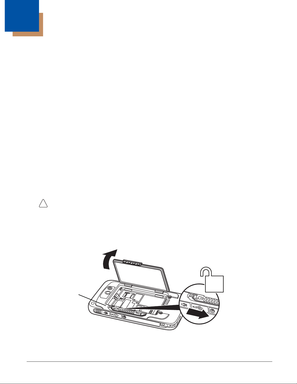
1
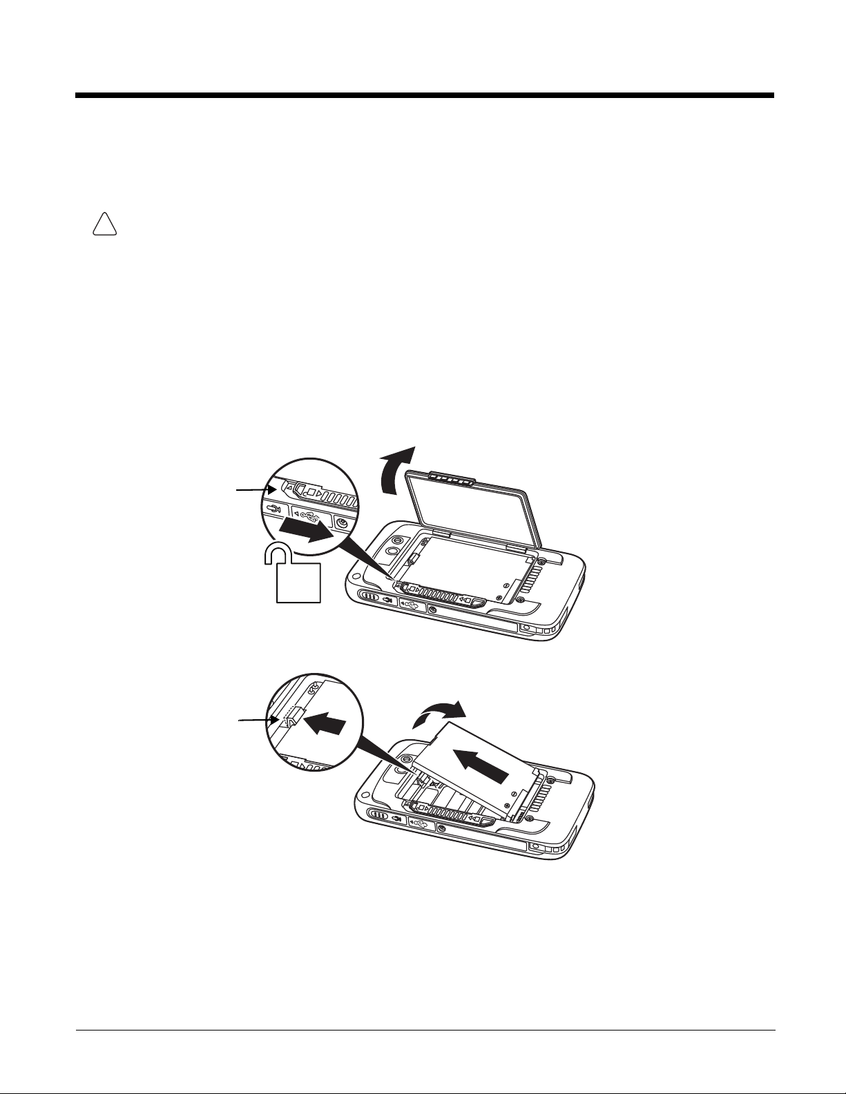
Battery Door Lock
Getting Started
Out of the Box
Verify that the carton contains the following items:
• Dolphin 75e handheld computer (terminal)
• 1 GB, 2 GB or 4 GB industrial grade microSD™ memory card (optional)
• Rechargeable 3.7V Li-ion battery
• USB charge/communication cable
• Power adapter with regional plug adapters
• Product documentation
If you ordered accessories for your terminal, verify that they are also included with the order. Be sure to keep the original
packaging in case you need to return the Dolphin terminal for service.
Memory Card Specifications
Honeywell recommends the use of Single Level Cell (SLC) industrial grade microSD or microSDHC™ memory cards with
Dolphin terminals for maximum performance and durability. Contact a Honeywell sales representative for additional
information on qualified memory card options.
Initial Setup for Dolphin 75e Terminal
Step 1. Install the Battery
Before installing the main battery, read the Guidelines for Battery Pack Use and Disposal on page 2-13.
The terminal is shipped with the battery packaged separate from the unit. To install the battery, follow the installation steps
illustrated. For information on how to remove the battery, see Replacing the Battery on page 1-11.
Ensure all components are dry prior to placing the battery in the terminal. Mating wet components may cause
damage not covered by the warranty.
We recommend use of Honeywell Li-ion battery packs. Use of any non-Honeywell battery may result in damage
not covered by the warranty.
Important: All battery and connector doors must be present, undamaged, and properly closed to maintain the
environmental rating of the terminal.
Note: Standard battery and standard battery door shown.
1 - 1
Page 14
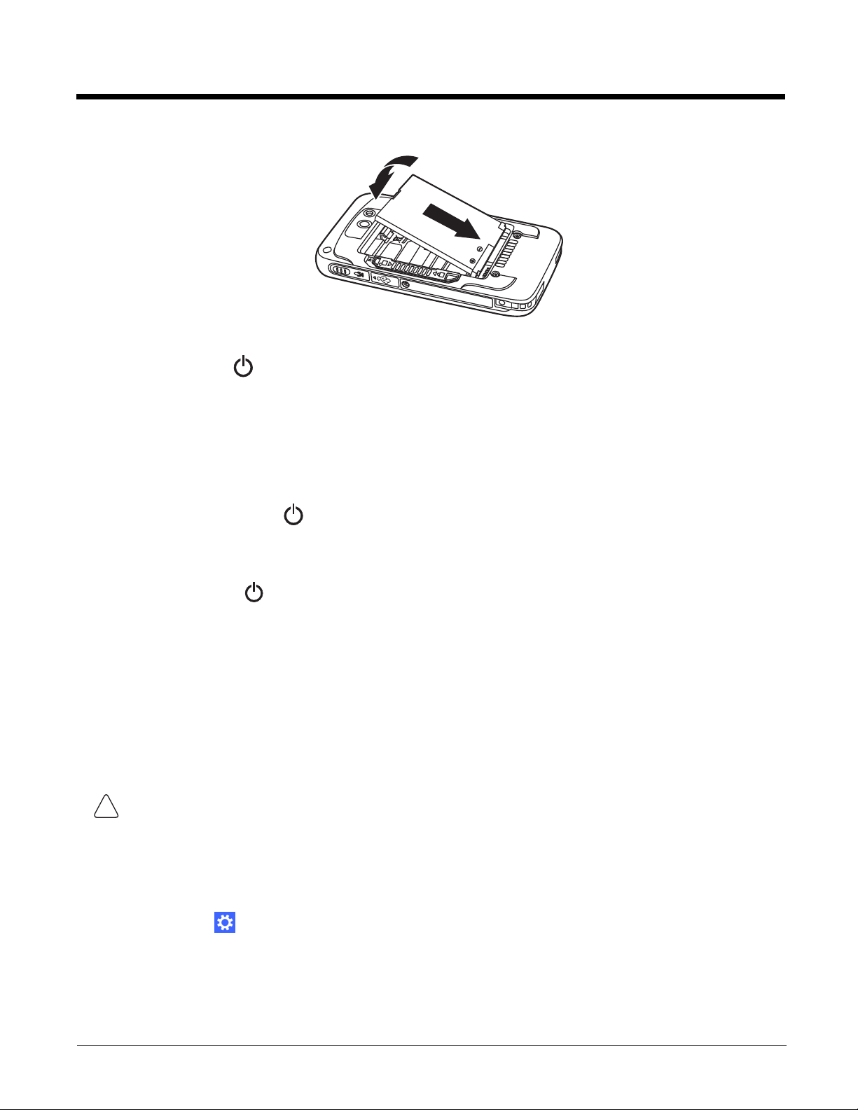
Step 2. Charge the Battery
3
4
5
6
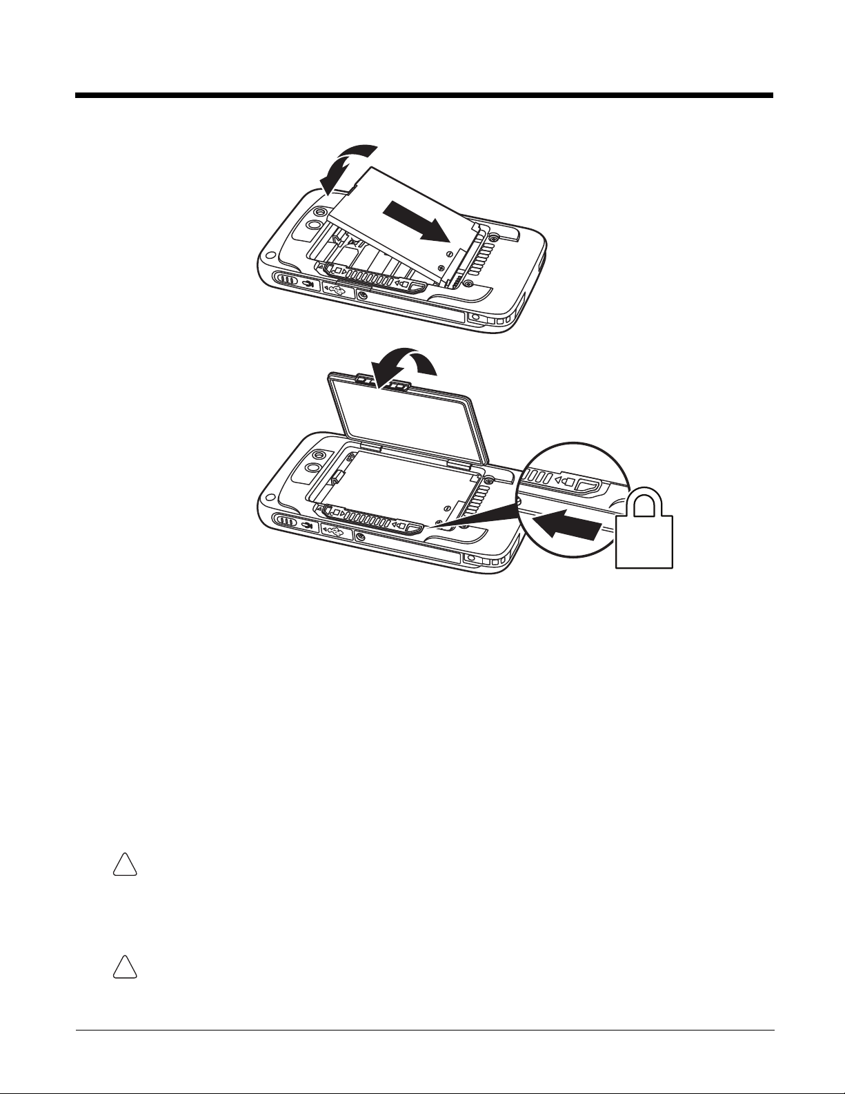
Apply pressure to the edges of the
battery door before engaging the lock to
ensure the door is properly closed.
!
!
The power source for the Dolphin terminal is the 3.7V Li-ion rechargeable battery located under the battery door on the
back panel of the device. See Battery on page 2-8 for additional information on battery storage, use, and disposal.
Important: Removing the battery from the terminal erases all non-persistent memory. Always power off the terminal before
removing the battery. For information on how to remove the battery from the terminal, see Replacing the Battery
on page 1-11.
Before Initial Use
Dolphin terminals ship with the battery significantly discharged of power. After installing the battery in the terminal, charge
the battery with a Dolphin 75e compatible charging peripheral for a minimum of 4 hours for the standard battery pack or
6 hours for the extended battery pack.
When using the 70e-USB Charge/Communication cable to charge from a 500mA USB port on a host device, charge the
battery for a minimum of 6 hours for the standard battery and 8 hours for the extended battery.
Note: Inadequate source current may interfere with effective battery charging; see Important Charging Guidelines on page
2-10 for additional information.
We recommend use of Honeywell peripherals, power cables, and power adapters. Use of any non-Honeywell
peripherals, cables, or power adapters may cause damage not covered by the warranty.
Dolphin 75e model terminals are designed for use with the following charging devices and cables: 70e-HB, 70e-CB,
70e-EHB, 70e-NB, 70e-MB, 70e-MC, and 70e-USB ADAPTERKIT. See pages 2-1 and 2-2 for additional information on
peripherals and accessories.
Ensure all components are dry prior to mating terminals/batteries with peripheral devices. Mating wet
components may cause damage not covered by the warranty.
1 - 2
Page 15
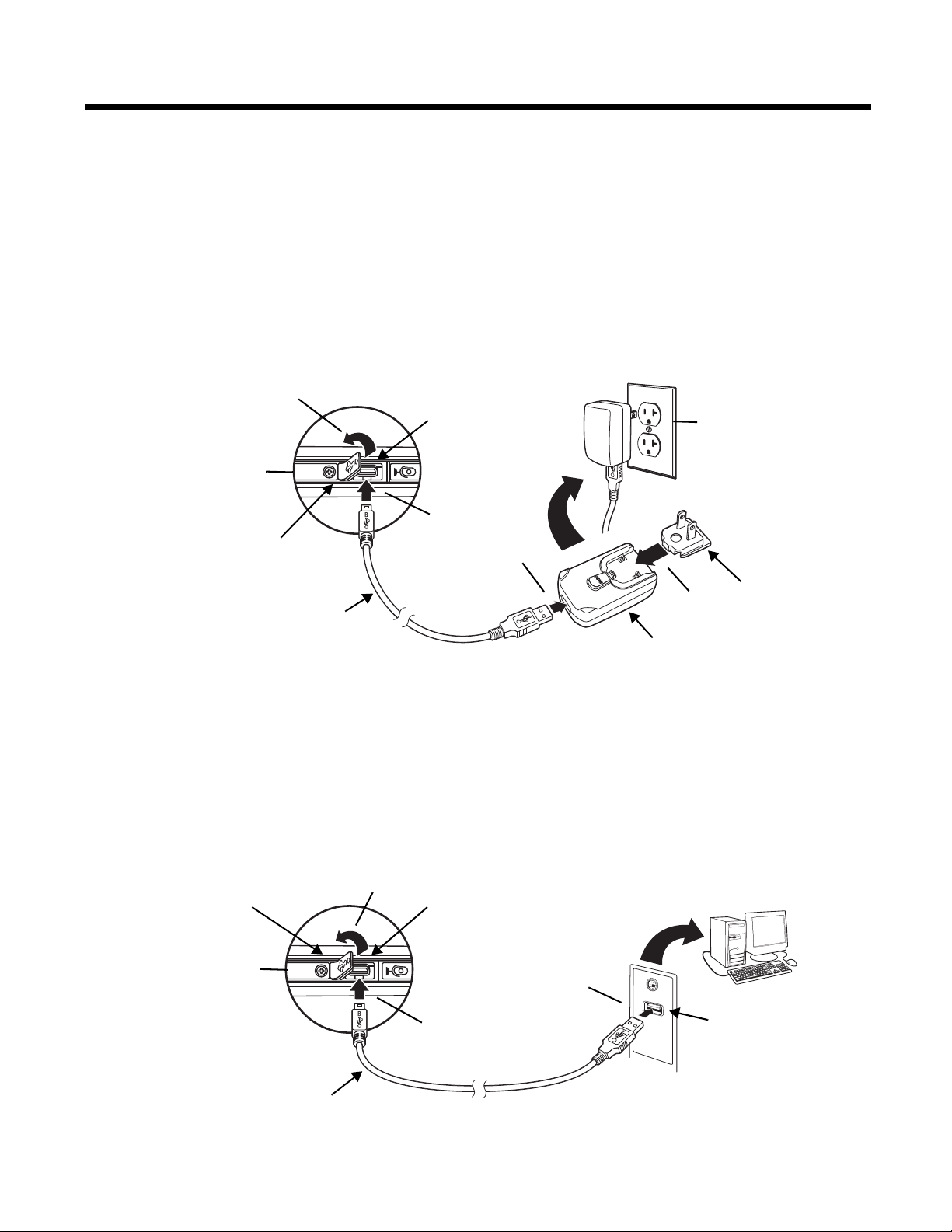
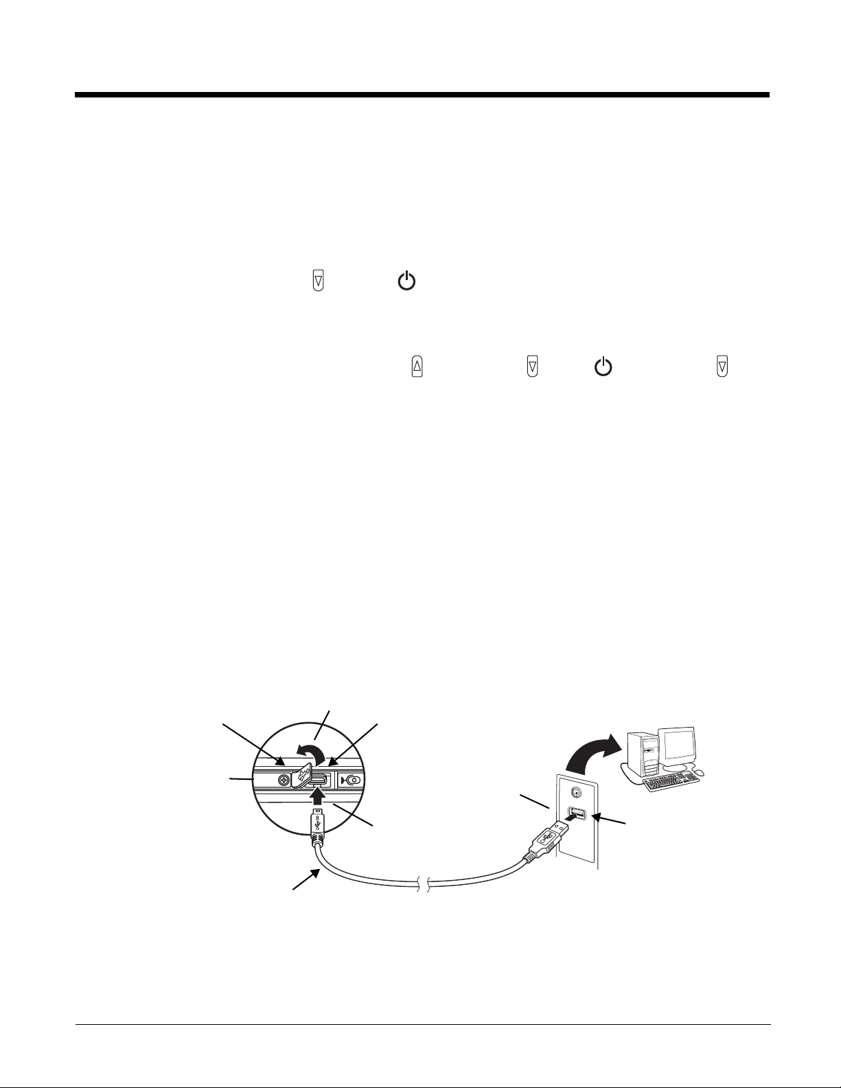
Using the USB Charge/Communication Cable (Model 70e-USB ADAPTERKIT)
USB Door
Plug Adapter
1
3
4
2
Micro USB Port
Power Adapter
5
Right Side Panel
of the Terminal
USB Charge/Communication Cable
USB Port
USB Door
1
3
2
Micro USB Port
Right Side Panel
of the Terminal
USB Charge/Communication Cable
Dolphin 75e terminals ship with a USB Charge/Communication Cable and a power adapter with regional plug
adapters. The USB Charge/Communication cable provides two options for charging the terminal. Use the cable in
conjunction with the provided power supply adapter and plug adapter to charge the terminal from a power outlet
(Option 1) or connect the cable to a high-power USB port to charge from a host device (Option 2).
Warning: The terminal shall only be connected to CTIA certified adapters, products that bear the USB-IF logo or
products that have completed the USB-IF compliance program when using the micro USB port as a
charging source.
Option 1: Charging from a power outlet
Use only a UL Listed power supply, which has been qualified by Honeywell with an output rated at 5VDC and 1A with
the device.
Option 2: Charging from a high power USB port on a host device (PC)
Charging the battery through a USB port takes more time than direct charging using the provided power supply.
Inadequate source current may lengthen the charge time or prevent the battery from charging if the terminal is drawing
more current than supplied by the USB port. The maximum current supplied by a USB Host can vary from 100mA to
500mA. Do not attempt to charge the terminal from a 100mA source. An active Dolphin terminal uses more current
than supplied by a 100mA source causing the terminal to continue to draw power from the battery.
See Important Charging Guidelines on page 2-10 for additional information.
Note: Placing the terminal in Sleep (Suspend) mode while charging reduces the current draw of the terminal and
shortens the charging time of the battery.
1 - 3
Page 16
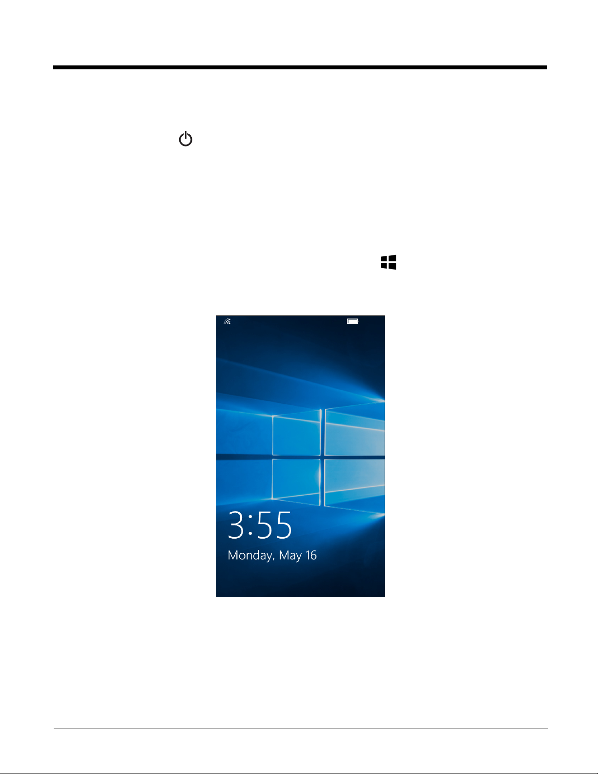
Step 3. Complete the First Time Consumer Setup
Screen Lock
To power on and set up the terminal:
1. Press the Power button .
2. Select a language, and then touch Next.
3. Select your region, and then touch Next.
4. Touch Cancel to bypass the advanced provisioning options and access the consumer setup.
5. Follow the on screen prompts for setting up the terminal, your WiFi connections, and creating a Microsoft® account
(optional). To learn more about what you can do with a Microsoft account, go to https://account.microsoft.com/about.
Unlocking the Screen
Swipe up from the bottom of the screen to unlock the terminal and access the Start screen.
For information on customizing the security feature, see Managing Security and Customizing the Screen Lock on page 5-2.
1 - 4
Page 17
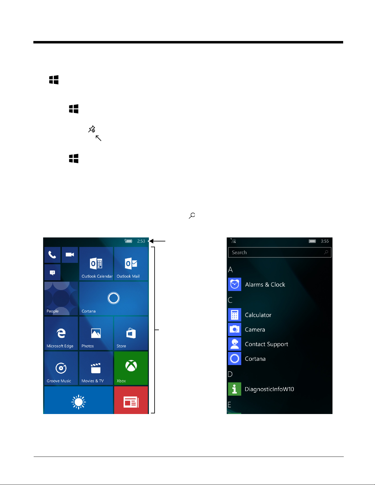
About the Start Screen and App Access
Tiles
Swipe left to view the
Apps list or down to
view more Tiles.
Start Apps List
Notification/Status Bar
Start is the first screen you see once you power on the terminal and unlock screen. You can add, delete, move, resize, or
group Tiles into folders for easy quick access. Tiles can be apps, contacts, maps, albums, or office files. Live Tiles provide
notifications and updates in real time (e.g., weather stats).
On Start , touch and hold a Tile, and then:
• Drag the Tile to a new location on the screen.
• Touch Unpin to delete the Tile.
•Touch the arrow to toggle through Tile sizes.
• Drag the Tile on top of another Tile you want in the same folder. Select Name Folder to customize the folder name
On Start , swipe left on the screen to access the Apps list.
• Swipe up and down to scroll through the apps.
• Touch the app icon/name to open the app.
• Touch and hold an app, and then select pin to start if you want to add it to the Start screen.
To find an app quickly from the list:
• Touch a letter to alphabetically search for an app.
• Enter the app name in the Search box, and then select .
Note: Due to model hardware differences, some inactive apps may appear on the App List even though they are not supported
by the Dolphin model type (e.g., the Phone app appears on WLAN only models). Selecting an inactive app icon has no
effect and will not cause any functional issues.
1 - 5
Page 18
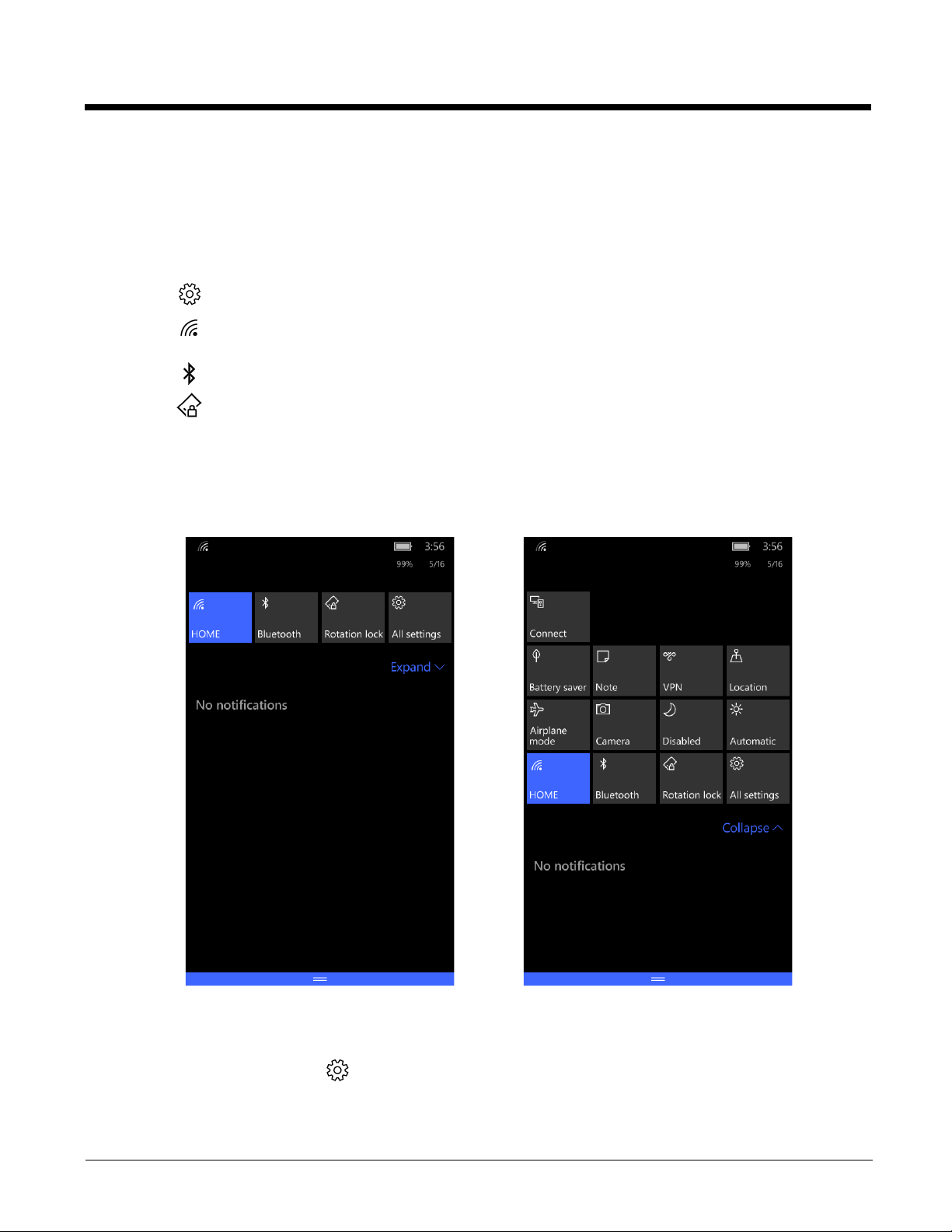
Accessing the Action Center from the Status Bar
Action Center
Expanded Action Center
To view the battery charge level (%), details about a notification or to quickly access and modify settings, touch and hold the
status bar at the top of the screen and then drag down.
• The battery charge level (%) shows in the upper right corner of the screen.
• Touch any notification to open the related app and access additional settings or information.
• Touch All Settings to access system and application settings.
• Touch to access the Wi-Fi settings screen where you can view available networks, add a Wi-Fi network, or turn
Wi-Fi networking On or Off.
• Touch to turn the Bluetooth technology on or off.
• Touch Rotation lock to turn on or off automatic screen rotation when you rotate the terminal 90 degrees.
Select Expand to view more quick actions.
To close the action center, swipe up from the bottom of the screen.
Customizing the Quick Actions
To customize the action center:
1. From the Action Center, select All Settings > System > Notifications & actions.
2. Touch the quick action you want to change.
3. Select a new app from the list.
1 - 6
Page 19
Changing Notification Behaviors
If you want to keep notifications hidden when the screen is locked:
1. From the Action Center, select All Settings > System > Notifications & actions.
2. Turn any of the following settings Off to limit access or hide notifications. By default, these settings are On .
• Show notifications in action center when my phone is locked.
• Show notification on the lock screen.
• Show and sound alarms and reminders when my phone is locked.
You can also set how and when specific apps show notifications. For more information, see Changing App Specific
Notifications on page 5-3.
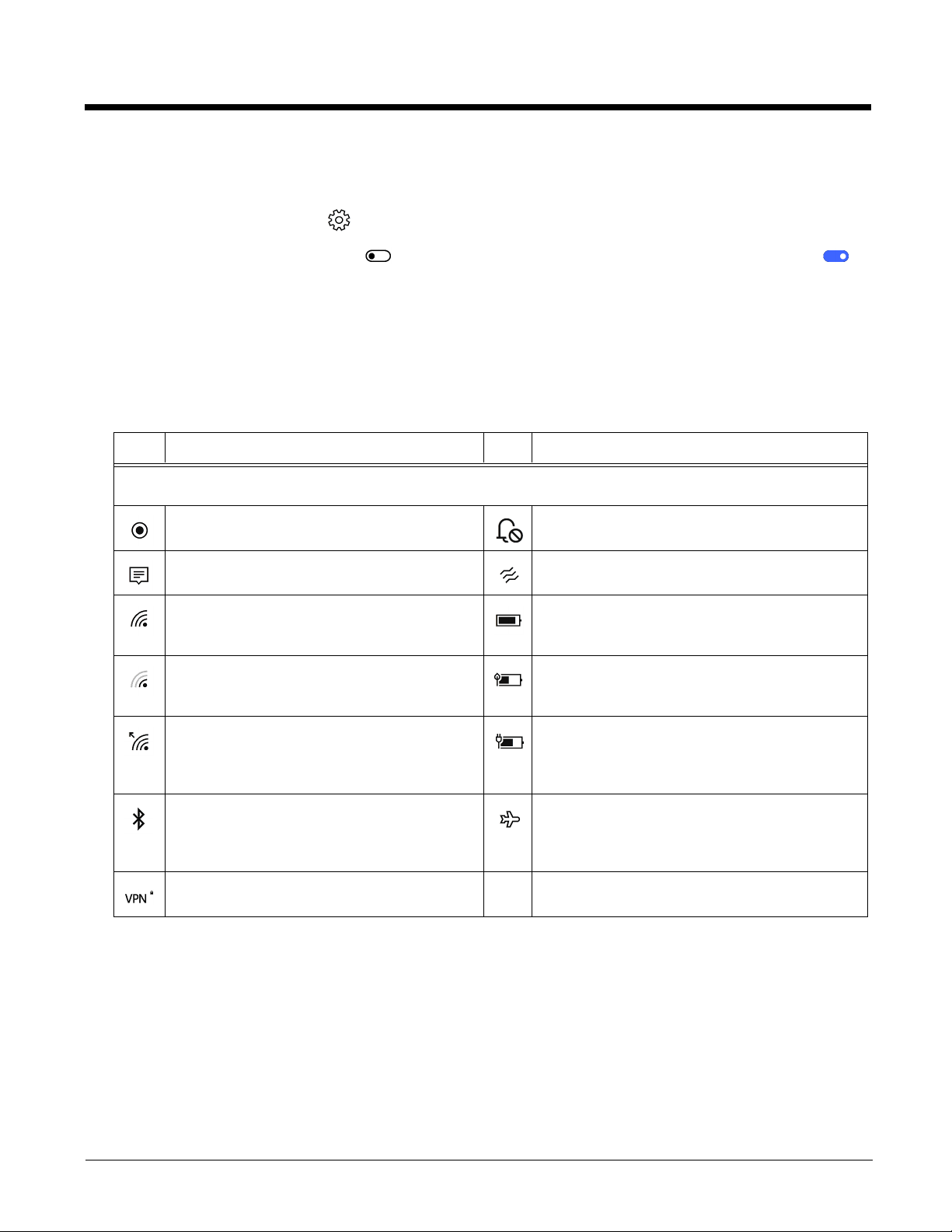
Common Status and Notification Icons
Icon Meaning Icon Meaning
Note: Status and notification icons are hardware and software dependent. Some of the icons listed below may not be
relevant for your Dolphin model.
An app or service is using terminal location
information.
New notification in the Action Center. Vibrate mode is turned On.
Wi-Fi is turned On, there is an active Wi-FI
network connection and the signal strength is
strong.
Wi-Fi is turned On, there is an active Wi-Fi
network connection but the signal strength is
weak.
Data is being transferred over the Wi-Fi network
connection.
Bluetooth is turned On, the terminal is paired to
another device with Bluetooth technology and the
connection between terminal and paired device is
active.
Terminal is connected to a Virtual Private
Network (VPN).
Note: To view details about the status of the WLAN (Wi-FI) and Bluetooth radio connections, swipe down from the top of
the screen to expand the Action Center.
Sound is turned Off.
Battery charge level left on the battery.
Battery saver mode is turned On.
Terminal is connected to external power.
When the battery is charging the battery charge and
external power icons toggle off and on.
Airplane mode is turned On.
1 - 7
Page 20

About Cortana Voice Assistant
Cortana is your personal assistant app that makes daily tasks easier and faster by using voice commands, simple
questions, and quick screen input. Here are some of the things Cortana can help you with:
• Send an e-mail or message.
• Schedule a meeting.
• Set a reminders for an important tasks or events.
• Check your location, get directions.
• Get up-to-date traffic and weather info.
To get started with Cortana you need an active Wi-Fi connection and a Microsoft account.
Press the Search button or the touch the Cortana tile on the Start screen.
This feature is not available in all languages or regions. For information on how to use Cortana or to view information on
availability, go to http://windows.microsoft.com/support. If you do not want to use Cortana or it is not available in your
country or region, you can still use the Speech functionality on your the terminal to input search criteria.
Turning Cortana Off
To turn Cortana On or Off:
1. Press the Search button .
2. Touch .
3. Select Notebook > Settings.
4. Turn Cortana Off
and restart the terminal.
Using Speech
If Cortana is turned off or unavailable in your region, you can still use Speech to input search criteria.
When you use the Microsoft speech recognition service, the words you speak and the supporting data are sent to Microsoft
to provide and improve the service. An active Internet connection is required and the “Get to know me” option under the
Privacy settings must be turned On.
To learn about turning on and adjusting the Speech feature, see Configuring the Speech Feature on page 5-12.
To start a search in the Bing browser:
1. Press the Search button to open the browser.
2. Select Search the web and Windows.
3. Touch the voice icon
Listening ... appears next to the icon when Speech is active and ready for a voice command.
4. Say what want to type in the search box.
5. Select from the preliminary search results or touch return
.
on the keyboard to see more.
1 - 8
Page 21
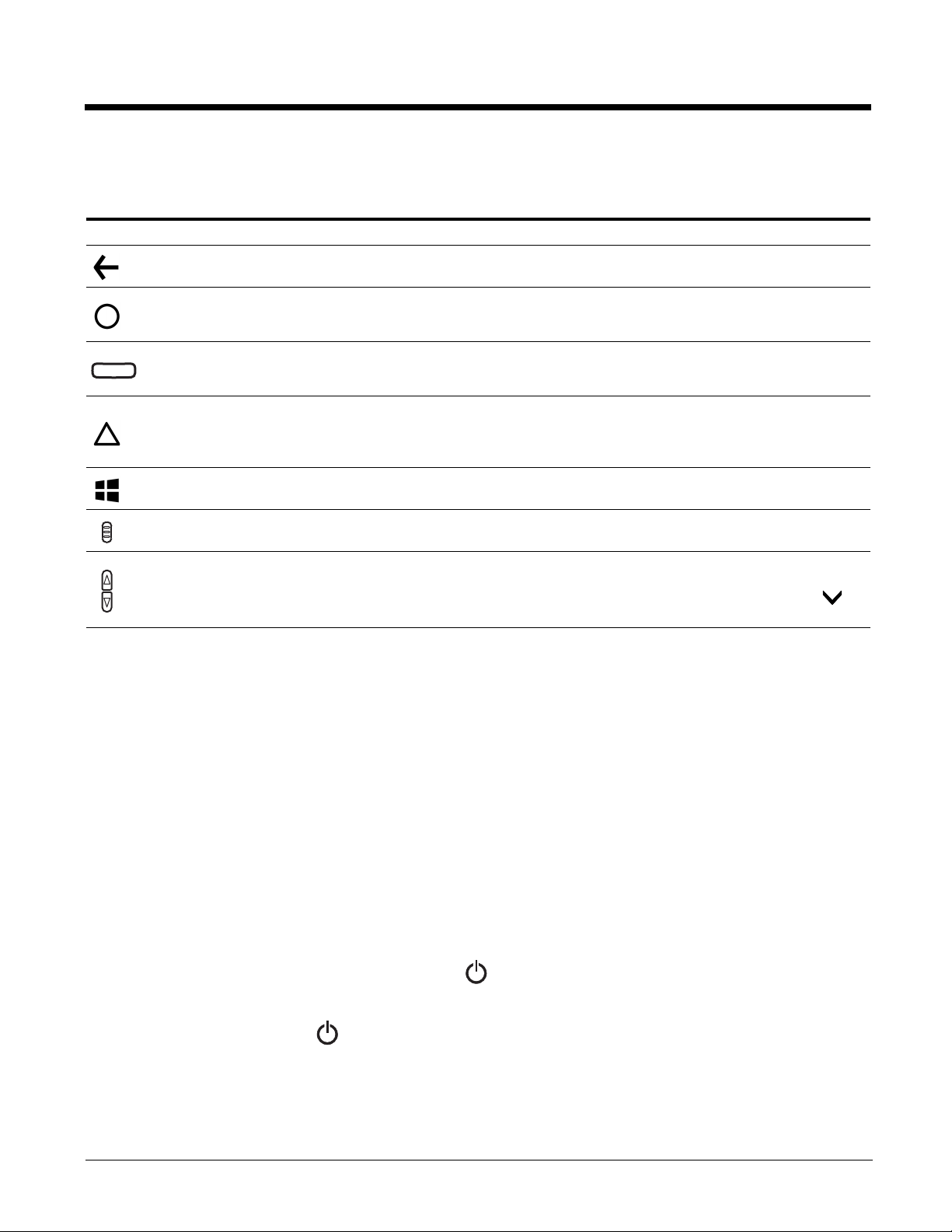
Navigation/Function Buttons
The Dolphin terminal has seven navigation/function buttons.
Button Function
Back Return to the previous screen or press and hold to open the App switcher.
Administrator
or Developer
Defined
Scan
Search
Start Return to the Start screen.
Right & Left
Side
Volume
By default, no function is assigned to this button. For information on advanced tools and
resources for IT professionals, go to https://technet.microsoft.com.
Wake the terminal from Sleep mode.
Trigger the scanner/imager.
If Cortana is turned Off, press to search the terminal and Web using Bing.
If Cortana is turned On, press to ask a question or initiate a voice command. To learn more
about Cortana, go to www.windowsphone.com.
Trigger the scanner/imager.
Press to raise or lower the volume of the active speaker. The status bar briefly expands when
you press either the volume up or down button.
Use the slider to adjust the volume for the Ringer + Notifications or touch the down arrow to
access the volume adjustment for Media and apps.
Virtual Keyboard
The virtual keyboard appears when you open an application or select a field that requires text or numerical input. The content of
the keyboard may vary depending on the application in use and the input field requirements.
Using the Virtual Keyboard
During text input, you may need to switch between keyboard modes to access additional character sets (e.g., function keys,
symbols, and numbers). Each keyboard mode, includes navigation keys, which allow you to quickly switch between modes.
Touch the abc key to switch to the Qwerty Mode, and the &123 key to switch to the Numeric Mode. Touch and hold the
period “.” key to access additional symbols (e.g., dash “-”, exclamation point “!”, question mark “?”, colon “:”) and
emoticons.
See Time and Language Settings on page 5-11 for additional information on configuring keyboard & input methods.
Note: The content of the keyboard and the mode initially displayed may vary depending on the application in use and the
input field requirements.
for
Turning Power On/Off
To turn the terminal On, press and release the Power button .
To turn the terminal Off:
1. Press and hold the Power button .
2. When the message, “slide down to power off” appears, release the button and swipe down toward the bottom of the screen.
You should always power off the terminal before removing the battery. For information on removing the battery, see Replacing
the Battery.
1 - 9
Page 22

Turning Sleep Mode (Suspend Mode) On/Off
To save battery power, the touch panel display dims, and then turns off after a period of inactivity. If the display stays off longer
than the set time limit, the terminal enters sleep mode.
To wake the terminal from sleep mode and unlock the screen:
1. Press and release the Power button .
2. Swipe up from the bottom of the screen to unlock the terminal.
To manually place the unit in Sleep mode, press and release the Power button .
To adjust the time out limits:
1. Touch Settings on the Apps list screen.
2. Do one of the following:
• Select Extras > sensor settings to adjust the time out limit for when the touch panel dims and turns off after a period of
inactivity.
• Select Personalization > lock screen to adjust the display lock (Sleep) time out limit.
Turning Airplane Mode On/Off
Tu r n Airplane mode on to quickly disable all the terminal radios that transmit voice or data.
Note: While in Airplane mode, you can still turn the Wi-Fi or Bluetooth radio back On.
To toggle Airplane Mode On or Off.
1. Swipe down from the top of the touch screen to open the action center.
2. Select Expand.
3. Touch Airplane mode to toggle the mode On or Off. When Airplane Mode is turned on, shows on the status bar.
1 - 10
Page 23
Replacing the Battery
!
Battery Door Lock
Battery Latch
Before replacing the battery, read the Guidelines for Battery Pack Use and Disposal on page 2-13. For battery replacement part
numbers, see Replacement Battery Specifications on page 2-9.
RISK OF EXPLOSION IF BATTERY IS REPLACED BY AN INCORRECT TYPE. The battery should be disposed of
by a qualified re-cycler or hazardous materials handler. Do not incinerate the battery or dispose of the battery with
general waste materials.
Ensure all components are dry prior to mating terminals/batteries with peripheral devices. Mating wet components
may cause damage not covered by the warranty.
We recommend use of Honeywell Li-ion battery packs. Use of any non-Honeywell battery may result in damage not
covered by the warranty.
The following illustrations depict a standard battery with a standard battery door; however, battery removal and installation
procedures are the same for the extended battery and extended battery door.
To replace the battery:
1. Power Off the terminal.
2. Unlock and remove the battery door.
3. Pull the battery latch back and remove the battery.
1 - 11
Page 24
4. Insert the new battery and install the battery door.
!
5. Apply pressure to the edges of the battery door to ensure the door is properly closed. Engage the door lock.
6. Press the Power button .
Important: All battery and connector doors must be present, undamaged, and properly closed to maintain the environmental
rating of the terminal.
Restarting the Terminal
You may need to restart the terminal to correct conditions where an application stops responding to the system or the terminal
seems to be locked up.
• Press and hold the Power button . When the message, “slide down to power off” appears, release the button and swipe
down toward the bottom of the screen. Press the Power button to turn the terminal back on.
To perform a restart if the touch panel display is unresponsive:
• Press and hold the Power button down for approximately 13 seconds. The terminal automatically restarts.
Resetting the Terminal
You may need to perform a Factory reset (clean boot) if you are transferring the terminal to a new owner that requires the use
of a different Microsoft account and a clean configuration without any of the custom apps, settings, and data you added. A reset
may also be required if the terminal has become unresponsive and all other recovery methods have failed. If you are transferring
ownership, use Method 1 (see below) to reset the terminal back to the factory state. If the terminal is unresponsive, use
Method 2 (on page 1-13).
When a reset is performed, all personal content is erased (e.g., emails, pictures, contacts) and all factory default settings are
restored on the terminal. The reset discards any account information you added, including your Microsoft account information.
Only installed Microsoft over-the-air (OTA) updates persist after a reset is performed.
Caution: A Factory Reset (Clean Boot) erases the memory in the terminal, including all applications and data files,
with the exception of those found in the removable storage. Any custom provisioning must be
reimplemented after a Factory Reset.
Method 1
To perform a Factory Reset (Clean Boot):
1. Touch Settings on the Apps list screen.
2. Touch System > About.
3. Select Reset your phone.
4. If you want to Also erase SD card, touch the box to select the option.
1 - 12
Page 25
5. If you want to Also remove provisioned content from my workplace, touch the box to select the option.
USB Port
USB Door
1
3
2
Micro USB Port
Right Side Panel
of the Terminal
USB Charge/Communication Cable
6. Touch Yes, and then Yes again to confirm restoring the factory settings.
Once the terminal resets, the language selection screen appears. For more information, see Complete the First Time
Consumer Setup on page 1-4.
Method 2
To perform a Factory Reset if your touchscreen is unresponsive and all other recovery methods have failed:
1. Press and hold the Volume Down
on the screen.
Note: Continue to hold the buttons down until the exclamation mark appears even if the Microsoft Feedback app tries
to load.
2. Press the following buttons in this order: Volume Up > Volume Down > Power > Volume Down .
Once the terminal resets, the language selection screen appears. For more information, see Complete the First Time
Consumer Setup on page 1-4.
and Power buttons simultaneously until a large exclamation mark appears
Connecting the Terminal to a Computer (PC) via a USB Connection
You can transfer files (e.g., pictures, music, and videos) between your computer and the terminal using the supplied USB
Charge/Communication cable or a Dolphin 70e Black HomeBase with a standard USB cable.
Note: The terminal supports Hi-Speed USB communication (USB 2.0) with a maximum data transfer rate of 480 Mbps.
Using the Windows Phone App to Connect
1. Connect the terminal to the PC using the USB charge/communication cable supplied.
2. If you have a computer running Windows® 10, open the Phone Companion app from Start > All apps.
If your have a computer running Windows 8 or Windows 8.1, the Windows Phone® app automatically opens when you
connect the terminal to the computer using the USB charge/communication cable supplied
If you have a computer running Windows 7 or Mac, go to www.windowsphone.com to download and install the Windows
Phone app for desktop or Mac.
3. In the Phone Companion app, select Windows as your terminal platform, and then set your sync preferences.
In the Windows Phone app, set your phone name and sync preferences. You can always modify your preferences later
by selecting Settings.
1 - 13
Page 26

Using File Explorer or Windows Explorer to Transfer Files
To move files between your Dolphin terminal and PC without using the app:
1. Connect the terminal to the PC using the USB charge/communication cable supplied.
2. Depending on the Windows operating system either open File Explorer or Windows Explorer.
3. Under Computer, click on Windows Phone > Phone.
4. You can now copy, delete and/or move files or folders between the computer and the terminal or a microSD card
installed in the terminal as you would with any other storage drive (e.g., cut and paste or drag and drop).
Changing USB Permissions and Notifications
1. In the Apps list, touch Settings .
2. Touch Devices > USB.
3. Select the options you want to turn On or Off .
• Ask me before allowing other PCs to connect to my mobile device using USB.
• Notify me if my mobile device is charging slowly over USB.
The Dolphin 75e should only be connected via its microUSB connector to CTIA certified adapters, products that bear the
USB-IF logo or products that have completed, the USB-IF compliance program.
1 - 14
Page 27

2
Hardware Overview
Standard Configuration for the Dolphin 75e
WLAN, WPAN, NFC & Camera
• Windows 10 IoT Mobile Enterprise
• Qualcomm APQ8074AB Processor
• 2GB RAM X 16GB Flash
• 3.7V Li-ion rechargeable standard or extended battery pack
• Dedicated imager capable of decoding standard 1D and 2D bar code symbologies
• 8.0 megapixel auto focus color camera
• 802.11a/b/g/n/ac and Bluetooth
• Near Field Communication (NFC) support
Peripherals for the Dolphin 75e
Each of the following items is sold separately to enhance the capabilities of your Dolphin terminal. Dolphin 70e Black
peripherals are compatible with Dolphin 75e terminals.
Dolphin 70e Black HomeBase (Model 70e-HB)
The HomeBase is a charging and communication cradle equipped with a USB host port that is Hi-Speed 2.0v compliant,
which enables the terminal to interface with the majority of PC-based enterprise systems. This device also contains an
auxiliary battery well that charges a spare Honeywell standard or extended battery pack.
For more information, see Dolphin 70e Black HomeBase (Model 70e-HB) on page 8-1.
Dolphin 70e Black eBase (Model 70e-EHB)
The Ethernet Base (eBase) enables a single Dolphin 75e terminal to communicate with a host device over an Ethernet
network. In addition, the ebase is equipped with a USB host port that is Hi-Speed 2.0v compliant, which enables the
terminal to interface with the majority of PC-based enterprise systems. This device also contains an auxiliary battery well
that charges a spare Honeywell standard or extended battery pack.
For more information, see Dolphin 70e Black eBase (Model 70e-EHB) on page 9-1.
Dolphin 70e Black Mobile Base (Model 70e-MB)
The Mobile Base is a charging cradle designed specifically for in-premise and in-transit data collection applications. It
features a flexible mounting bracket, an integrated speaker with volume control, and a cigarette lighter adapter to adapt it to
your mobile environment.
For more information, see Dolphin 70e Black Mobile Base (Model 70e-MB) on page 10-1.
Dolphin 70e Black ChargeBase (Model 70e-CB)
The ChargeBase is a 4-slot charging cradle that holds, powers, and charges terminals.
For more information, see Dolphin 70e Black ChargeBase (Model 70e-CB) on page 11-1.
Dolphin 70e Black Net Base (Model 70e-NB)
The Net Base enables up to four Dolphin 75e terminals to communicate with a host device over an Ethernet network. In
addition, the Net Base provides a second RJ45 Ethernet port for connection to an additional device such as a printer,
workstation, eBase, or another Net Base.
For more information, see Dolphin 70e Black Net Base (Model 70e-NB) on page 12-1.
QuadCharger (Model COMMON-QC)
The QuadCharger is a compact 4-slot battery charging station designed for use with Dolphin 75e 3.7V Li-ion rechargeable
batteries. For additional information on the common QuadCharger, visit the Dolphin 75e product page at
www.honeywellaidc.com or contact your local sales representative.
2 - 1
Page 28

Accessories for the Dolphin 75e
Each of the following items is sold separately to enhance your terminal’s capabilities.
Note: When using accessories where the terminal is worn on the body, the terminal’s touch panel must face away from the
body.
Dolphin 70e Black Mobile Charger (Model 70e-MC)
The Mobile Charger is a charging cable that connects the terminal directly to a 12 Volt DC power source, such as a
cigarette lighter port inside a vehicle, eliminating the need for a cradle. Intelligent battery technology on-board the terminal
ensures proper charging. The Mobile Charger is an ideal low-cost charging solution for in-transit mobile applications.
USB Charge/Communication Cable Adapter Kit (Model 70e-USB ADAPTERKIT)
The Dolphin USB charge/communication cable adapter kit is an all-in-one solution for charging and communication. Use
the 70e-USB cable in conjunction with the included power supply adapter and plug adapter to charge the terminal from a
power outlet or connect the cable to a high-power USB port to charge from a host device. The 70e-USB cable also supports
communication with a computer without the need for a cradle. See Connecting the Terminal to a Computer (PC) via a USB
Connection on page 1-13.
Holsters (Model HOLSTER-2 and 6000-HOLSTER)
A holster provides convenient storage for the Dolphin 75e terminal in mobile environments. Long and short holster models
with integrated belt clips and spare battery pouches are available.
Wrist Lanyard (Model SL-LANYARD-1)
The black wrist lanyard attaches to the bottom corner of the terminal providing additional security from accidental drop
during terminal use.
Stylus (Model 75e-Stylus)
The stylus has a special tip for added accuracy and ease when operating the touch panel. The tether is a coiled, elastic
cord, which secures the stylus to the terminal to prevent accidental loss. The stylus may be ordered with or without the
tether.
Battery Door Kits
Replacement battery door kits are available for both standard and extended battery door types. See Important Battery and
Battery Door Replacement Guidelines on page 2-9 before ordering battery door kits for your terminal.
Battery (Models 70e-BTSC and 70e-BTEC)
The 3.7V Li-ion rechargeable battery provides the main power for the terminal. See Battery on page 2-8 for battery
specifications, replacement part numbers, and guidelines for use and disposal.
Protective Rubber Boot (Model 70e-BOOT)
Protective Black Rubber Enclosure provides added protection.
2 - 2
Page 29
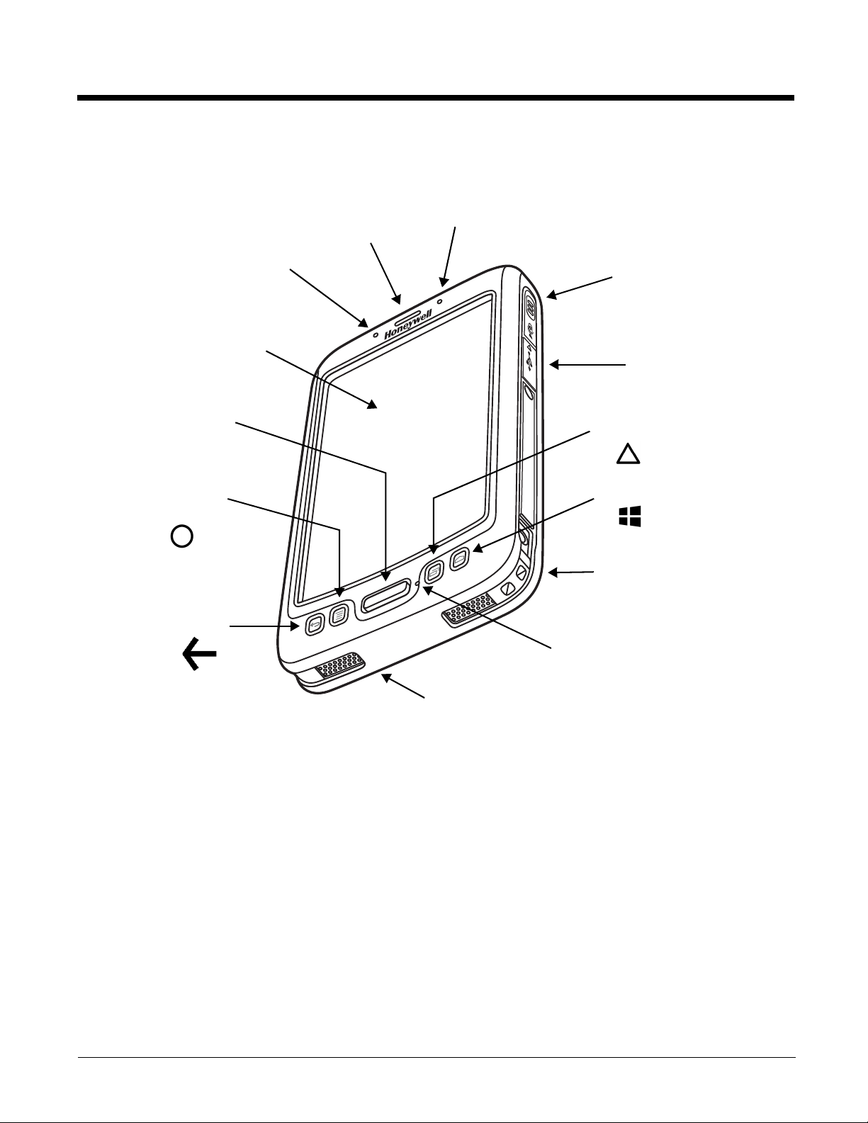
Features of the Dolphin 75e
Search Button
Touch Panel
Scan Button
Front Speaker
Battery Status and Notification LED
Back Button
Front Digital Microphone
Scan Status LED
USB Door/Micro USB Port
Administrator or
Developer Defined
Button
Right Scan Button
Start Button
Bottom Speaker
Fastener for an Optional Wrist Lanyard
or Stylus Tether
Front, Bottom, and Right Panels
For a description of each callout, see page 2-4.
2 - 3
Page 30

Feature Descriptions: Front, Bottom, and Right Panels
Back Button
The Back button returns you to the previous screen. When you press and hold the Back button, the App switcher
opens allowing you to view and switch between recently used apps.
Bottom Speaker
The integrated bottom speaker sounds audio signals as you scan bar code labels and enter data. The integrated speaker
also supports playback of wave and MP3 files, software mixer, and speaker phone for VoIP audio.
Digital Microphone
The integrated digital microphone, located on the front of the terminal provide audio input for handset VoIP calls when a
headset is not plugged into the Audio Jack (see page 2-7). When a headset is plugged into the Audio Jack, the terminal
defaults to the microphone on the headset. By default, the front microphone is also used for speaker phone VoIP calls,
voice command audio input, and recording sound.
Front Speaker
The front speaker is the receiver for handset VoIP calls.
Fastener for an Optional Wrist Lanyard or Stylus Tether
The fastener provides access for attaching an optional wrist lanyard or stylus tether.
Battery Status and Notification LED
The light emitting diode (LED) located above and to the right of the display panel indicates the battery charge status. The
LED also illuminates briefly during power up and a reboot. For detailed information on settings and meanings, see
Understanding the Battery Charge Status LED Indicator on page 2-10.
The LED may also flash blue if the notifications setting has been turned on for select applications. To learn how to change
app notification settings, see Changing App Specific Notifications on page 5-3.
Start Button
The Start button returns you to the Start screen, see page 1-9.
Administrator or Developer Defined Button
By default this button is left unassigned (open) for advanced administrator and developer customization. To learn
more about Microsoft advanced tools and resources for IT professionals, go to https://technet.microsoft.com.
Right Scan Button
The right button triggers the scanner/imager.
Search Button
The Search button functions differently depending on your Cortana or Speech settings. If Cortana is turned Off,
press the button to search the terminal and Web using the Bing browser. If Cortana is turned On, press to ask a question
or initiate a voice command. To learn how to turn Cortana On or Off, see About Cortana Voice Assistant on page 1-8.
Scan Button
The Scan button functions as a system wake-up control if the terminal has entered Sleep mode (Suspend mode). The
button also triggers the scanner/imager.
2 - 4
Page 31

Touch Panel
The color 4.3 inch WVGA (480 x 800 resolution) multi-touch capacitive touch panel is covered with an industrial protective
lens for greater durability. The touch panel can be activated with a finger or with the optional stylus.
Note: To conserve battery power the touch screen dims and then turns off after a period of no activity. Press the Power
button to wake the terminal from Sleep Mode (Suspend mode). See Managing Security and Customizing the Screen
Lock on page 5-2 for information on how to adjust sleep (timeout) settings.
USB Door/Micro USB Port
The micro USB port is located under the protective USB door on the right side of the terminal. To access the micro USB
port, gently lift the top edge of the door closest to the side scan button.
The micro USB port in conjunction with the USB Charge/Communication Cable Adapter Kit powers the terminal, charges
the main battery and facilitates communication. The micro USB port supports low, full, and high-speed USB v2.0 client
communication with a maximum rate of 480 Mbps.
For additional information, see Using the USB Charge/Communication Cable (Model 70e-USB ADAPTERKIT) on page 1-3.
and Connecting the Terminal to a Computer (PC) via a USB Connection on page 1-13.
The Dolphin 75e should only be connected via its microUSB connector to CTIA certified adapters, products that bear the
USB-IF logo or products that have completed, the USB-IF compliance program.
Scan Status LED
The light emitting diode (LED) located above and to the left of the LCD display flashes and illuminates during
scan/ image capture to provide scan status information. For additional information on the scan engine, see Using the Scan
Image Engine on page 3-1.
2 - 5
Page 32

Back, Top, and Left Panels
Image Engine Window (LED Aperture)
Camera Flash
Color Camera Lens
Battery Latch
(battery and battery door not shown)
Power Button
Left Scan Button
I/O Connector (see page 2-8)
Audio Jack
Volume Control Button
Battery Door
(standard model shown)
Memory Retention Flap
Memory Card Socket
Battery Door Lock
For a description of each callout, see page 2-7.
2 - 6
Page 33

Feature Descriptions: Back, Top, and Left Panels
Audio Jack
The audio jack is located under the protective door on the top of the terminal. To access the jack gently lift the edge of the
door marked with an arrow. The 3.5mm audio jack supports both speaker (stereo) and microphone (mono) headsets.
Battery
The 3.7V Li-ion rechargeable battery provides the main power for the terminal and is protected by the battery door. See
Battery on page 2-8 for battery specifications, replacement part numbers, and guidelines for use and disposal.
Battery Door
The battery door protects the battery and any installed SIM and/or memory cards in the terminal’s battery well. Proper
installation of the battery door preserves the environmental rating of the terminal. Do not use the terminal without the
battery door installed.
Battery Door Lock
The battery door lock secures the battery door to the terminal. Slide the lock down toward the IO contacts to release the
lock for battery door removal and battery access. Slide the lock up toward the camera lens to secure the battery door
closed and seal the battery in the terminal.
Battery Latch
The battery latch secures the battery in the battery well. Pull the latch away from the battery to release and remove the
battery from the terminal. For information on Replacing the Battery, see page 1-11.
Color Camera
The 8.0-Megapixel Resolution color camera provides easy picture and video capture. The camera lens and camera flash
are located on the back panel of the terminal.
Camera Flash
The camera flash is located on the back panel of the terminal. When used as a Camera Flash with the integrated color
camera, the flash is controlled by the camera application.
Image Engine Window
The image engine reads and decodes linear, stacked linear (e.g., PDF417), and 2D matrix bar code symbologies. The LED
aperture for the imaging engine’s LED aimer is contained behind this window. For more details, see Using the Scan Image
Engine on page 3-1.
Left Scan Button
The Left button triggers the scanner/imager.
Memory Card Socket
The memory card socket gives you the option to expand the terminal’s memory capacity using microSD or microSDHC
memory interfaces. The expansion socket is located under the battery door and battery.
When the battery door and battery pack are properly installed, the card is sealed against moisture and particle intrusion,
read/write data is stored securely, and the terminal’s environmental rating is preserved; see Installing a Memory Card on
page 2-14.
Memory Retention Flap
The retention flap locks the memory card in the socket; see Installing a Memory Card on page 2-14.
2 - 7
Page 34

Power Button
Pin 9 Pin 1
The Power button , located on the top of the terminal, initiates multiple functions depending on the length of time the
button is pressed. For information about how use the button to:
• Turn Power On or Off, see page 1-9.
• Turn Sleep (Suspend Mode) On or Off, see page 1-10.
• Restart the terminal if the touch screen is unresponsive, see page 1-12.
Volume Control Button
Press the top or bottom of the volume button to raise or lower the volume of the active speaker. Lower the volume all the
way down to turn off the volume and enable vibration only mode.
The status bar on the touch screen briefly expands when you press either the volume up or down button. Use the slider to
adjust the volume for the Ringer + Notifications or touch the down arrow to access the volume adjustment for Media
and apps.
The I/O Connector
The I/O connector powers the terminal, charges the main battery, and facilitates communication. Dolphin 70e Black peripherals
are designed to work exclusively with this connector. The I/O connector supports low, full, and high speed USB v2.0
communication with a maximum rate of 480 Mbps.
Pin Signal Description Terminal Back Panel
1 VDC_IN 5V DC input for charging and operation
2 VBUS_HOST 5V output for USB host and peripheral power
3 USB_DM_HOST USB D- for the host port
4 USB_DP_HOST USB D+ for the host port
5 USBC_DET Multipurpose pin to allow for detection of an
unpowered SLED, determine SLED type, and to
signal a HomeBase the docking of the terminal.
6 GND Ground connection
7 USB_DN_DOCK USB D- for the client port
8 USB_DP_DOCK USB D+ for the client port
9 VBUS_DOCK 5V input for USB client (and charging)
Note: Signals referenced are for a DTE device.
Battery
The primary power source for the Dolphin terminal is the 3.7V Li-ion rechargeable battery located under the battery door on the
back panel of the device. Honeywell recommends, you keep the battery in the terminal charged at all times to help prevent data
loss. Letting the battery become fully discharged causes the terminal to lose all data in RAM.
Note: All data in RAM is cleared when the battery is removed. Always power off the terminal before removing the battery to
ensure any changes made are saved to the flash memory.
2 - 8
Page 35

Replacement Battery Specifications
!
Start Action Center
Dolphin 75e model terminals are designed for use with battery part numbers BAT-STANDARD-02 (Li-ion 3.7V, 6.179 watt
hour) and BAT-EXTENDED-02 (Li-ion 3.7V, 12.358 watt hour) manufactured for Honeywell International Inc. For information
on how to replace the battery, see page 1-11.
Important Battery and Battery Door Replacement Guidelines
Follow the guidelines listed below when ordering batteries and/or battery doors.
• Size (e.g., standard or extended): The battery and battery door must be the same size.
• Type (e.g., locking or non-locking): Dolphin 75e models are only compatible locking type battery doors.
• Near Field Communication (NFC) requirements: Use only NFC compatible battery doors with NFC equipped Dolphin
models identified with the letter N at the end of the model number (e.g., 75exxN).
We recommend use of Honeywell Li-ion battery packs. Use of any non-Honeywell battery may result in damage
not covered by the warranty.
Important: All battery and connector doors must be present, undamaged, and properly closed to maintain the
environmental rating of the terminal.
Battery Authorize Failed
If a “Battery Authorize failed” notification appears, replace the battery with a qualified Honeywell Li-ion battery pack. The
battery does not charge if authentication fails.
Charging Options
Dolphin 75e terminals ship with the battery significantly discharged of power. Before using a terminal for the first time,
charge the battery with a Dolphin charging device for a minimum of 4 hours for the standard battery and 6 hours for the
extended battery.
When using the 70e-USB Charge/Communication cable to charge from a 500mA USB port on a host device, charge the
battery for a minimum of 6 hours for the standard battery and 8 hours for the extended battery.
Use one of the following chargers when the main battery is installed in the terminal:
• Dolphin 70e Black HomeBase (Model 70e-HB), see page 8-1
• Dolphin 70e Black eBase (Model 70e-EHB), see page 9-1
• Dolphin 70e Black Mobile Base (Model 70e-MB), see page 10-1
• Dolphin 70e Black ChargeBase (Model 70e-CB), see page 11-1
• Dolphin 70e Black Net Base (Model 70e-NB), see page 12-1
• Dolphin 70e USB Charge/Communication Cable (Model 70e-USB ADAPTERKIT) included with terminal, see page 1-13
To charge the battery when it is not installed in the terminal:
• Place the battery pack in the Auxiliary Battery Well of the Dolphin 70e Black HomeBase (Model 70e-HB) or the Dolphin
70e Black eBase (Model 70e-EHB).
• Insert the battery in the QuadCharger (Model COMMON-QC), see page 2-1.
2 - 9
Page 36

Charging Times
Charging Peripheral/Accessory
HomeBase (Model 70e-HB) 4 hours 6 hours
eBase (Model 70e-EHB) 4 hours 6 hours
ChargeBase (Model 70e-CB) 4 hours 6 hours
Net Base (Model 70e-NB) 4 hours 6 hours
Mobile Base (Model 70e-MB) 4 hours 6 hours
Mobile Charger (Model 70e-MC) 4 hours 6 hours
USB Charge/Communication Cable with provided power
supply (Model 70e-USB ADAPTERKIT)
USB Charge/Communication Cable (Model 70e-USB)
connected to a workstation (PC) 500mA USB port
QuadCharger (Model COMMON-QC) 4 hours 6 hours
Model: 70e-BTSC Model: 70e-BTEC
BAT-STANDARD-02 BAT-EXTENDED-02
4 hours 6 hours
6 hours 8 hours
Understanding the Battery Charge Status LED Indicator
The activity of the Battery Charge Status LED provides feedback about the charge level and charging status of the battery
in the terminal.
Terminal is Connected Charger LED Illumination Battery Charge Level
No Blinking Red Battery level is below 15%
No Off Battery level is 15% or more
Yes Steady Amber Battery level is between 0% and 60%
Yes Blinking Green Battery level is between 61% and 95%
Yes Steady Green Battery level is above 95%
Either Blinking Red Battery error
Important Charging Guidelines
Source Current Specifications
Battery charging times can be significantly lengthened or charging may not occur if the terminal is drawing more
currant than is supplied by the charging peripheral (e.g., HomeBase, eBase, Mobile Base, or ChargeBase), USB wall
charger, or USB Host (e.g., workstation PC).
• The maximum current supplied through a charging peripheral is 2.0A.
• The maximum current supplied by the USB wall charger is 900mA.
• The maximum current supplied by a USB Host can vary from 100mA to 500mA.
Do not attempt to charge the terminal from a 100mA source. An active Dolphin terminal uses more current than
supplied by a 100mA source causing the terminal to continue to draw power from the battery.
Note: Placing the terminal in Sleep Mode (Suspend mode) while charging reduces the current draw of the terminal and
shortens the charging time of the battery.
On Start , swipe left to view the App list. Select Settings > Devices > USB. Turn On “Notify me if my mobile
device is charging slowly over USB”.
Charging a Severely Low or Completely Discharged Battery
The terminal powers off if the battery charge goes below 5%. If you press the power button and a low battery image
briefly appears on the screen but the unit does not start, the battery charge is too low to boot. Connect the
terminal to an AC power source for charging. When you first connect the terminal to the charger, the battery charge
2 - 10
Page 37

status LED on the terminal briefly turns red, then Off and back On to a steady amber. As the battery charge reaches
approximately 2%, the a battery charging icon temporarily appears and flashes from to on the terminal
screen. Once the battery reaches a safe charge threshold (approximately 7%), the terminal starts to boot. The length
of time before the battery reaches a safe charge threshold varies depending on the extent of the battery discharge.
Note: If you are charging the terminal from a USB host device (PC) using the USB Charge/Communication Cable, the
length of time before the battery reaches a safe charge threshold varies depending on the extent of the initial
battery discharge level and the current supplied by the USB charging source. Inadequate source current may
interfere with effective battery charging.
Checking the Battery Health
On the Settings screen, select Extras > battery status settings for battery health information. Swipe left or right on
the touch screen to scroll between the battery state, battery log and about battery screens.
Viewing the Battery State
On the battery state screen, you can view statistics about the battery including the:
• Battery life percent—This statistic indicates the percentage of charge left on the battery.
• Time to empty
•Voltage
• Current
• Temperature
• State of Health—This battery health percentage provides an indication of the recharging life left on the battery. A Liion battery can be recharged many times but the battery life is still limited.
• Cycle count
• Serial Number
To conserve battery power and view app power consumption statistics, see Checking Battery Power and Monitoring
Battery Power Use on page 2-12.
Turning on the Battery Log
When the battery log feature is enabled, battery state related events and statistics are logged and displayed on the
screen. The default logging interval is 5 minutes but can changed to 10 minutes, 15 minutes, 30 minutes, or
60 minutes. The first three fields note the date, time and event type. Additional information logged is determined by the
event type. Events include:
•TIME LOG
• BATT REMOVAL (when AC is connected)
• BATT PRESENT
• BATT CHANGE
• BATT CRITICAL
• BATT FULL
• POWER ON LINE (for external VDC_IN)
• POWER USB DCP (for a dedicated charger connected)
• POWER USB FULL (for 500mA USB client connection)
• POWER USB LIMITED (for a USB power source is present but only available at 100m)
To enable the logging feature:
1. Swipe left from the battery state screen to view the battery log screen.
2. Touch the box next to Enable Log to turn On the battery Time log feature. By default, the battery Time log setting
is turned Off (no check in the box).
3. Select the Interval Time (minutes) for logging events. As events are logged, they appear on the screen.
4. Select to save your settings.
2 - 11
Page 38

Managing Battery Power
Battery Saver
Letting the battery become fully discharged causes the terminal to lose all data in RAM. Honeywell recommends, you keep
a charged battery in the terminal at all times to help prevent data loss. Removing the battery from the terminal erases all
non-persistent memory.
When the terminal is running on battery power (as opposed to external power), warnings are displayed when the battery
reaches critical and low battery points.
Checking Battery Power and Monitoring Battery Power Use
To view battery statistics about the battery charge:
1. Select Settings on the App list.
2. Touch System > Battery saver.
The Overview provides the battery charge level (%) and a remaining time estimate. If the terminal is connected to
an external power source, the charge status is shown with an estimated time to a full charge.
Touch Battery use to view and adjust how individual apps consume the battery power (see page 2-13).
2 - 12
Saving Battery Power by Turning Off All Nonessential Features and Background Tasks
To conserve battery power, you can enable the Battery saver to turn off all nonessential features and tasks that run in
the background consuming battery power. This includes but is not limited to automatic updates to your email, calendar,
and some Live Tiles that use a push notification for updates.
To temporarily enable the Battery saver:
1. Select Settings > System > Battery saver.
2. Turn On the Battery saver feature. The saver stays on until the next time you charge the terminal. Once a
charge cycle is initiated, the terminal switches back to normal battery usage.
Page 39

To set the battery saver to automatically turn on:
1. Scroll down to the bottom of the Battery saver screen and select Battery saver settings.
2. Check the box to automatically turn the battery saver on if the charge level drops below a set percentage.
3. Use the slider to set the battery level percentage.
To define apps you want to keep exempt from the Battery saver restrictions:
1. Select Battery saver settings.
2. Touch to add an app.
3. Select the app to exclude from the battery saver restrictions. Adding apps reduces the efficiency of the Battery
Saver.
Limiting Background Usage for a Specific Application
If you only want to adjust how a specific app consumes battery power by running in the background:
1. Select Settings > System > Battery saver.
2. Touch Battery use.
3. Select Change background app settings.
4. Select the On or Off toggle box to set background permission for the app.
Disabling the Button Backlights and Enabling the Smart Sensors to Conserve Power
To learn how to reduce power consumption by turning off the backlight on the terminal buttons, see Changing the
Button Illumination Settings on page 5-16.
To learn about configuring the integrated motion detection sensors for advanced power management, see Modifying
the Sensor Settings on page 5-16.
Storing Batteries
To maintain top performance from batteries, avoid storing batteries outside of the following temperature ranges:
• 14°F to 113°F (-10°C to +45°C) for short term storage of less than one month
• 32°F to 86°F (-0°C to +30°C) for long term storage
Do not store batteries in extremely high humidity. For prolonged storage, do not keep batteries stored in a charger that is
connected to a power source.
Guidelines for Battery Pack Use and Disposal
The following are general guidelines for the safe use and disposal of batteries:
• Do not disassemble or open crush, bend or deform, puncture or shred.
• Do not modify or remanufacture, attempt to insert foreign objects into the battery, immerse or expose to water or other
liquids, expose to fire, explosion or other hazard.
• Improper battery use may result in a fire, explosion or other hazard.
• We recommend use of Honeywell Li-ion battery packs. Use of any non-Honeywell battery may pose a personal hazard
to the user.
• Only use the battery for the system for which it is specified. Do not use a battery in any other manner outside its intended
use in Dolphin terminals and peripherals.
• Only use the battery with a charging system that has been qualified with the system per standard IEEE-Std-1725-2006.
Use of an unqualified battery or charger may present a risk of fire, explosion, leakage, or other hazard.
• Replace the battery only with another battery that has been qualified with the system per this standard, IEEE-Std-1725-
2006. Use of an unqualified battery may present a risk of fire, explosion, leakage or other hazard.
• Replace defective batteries immediately; using a defective battery could damage the Dolphin terminal.
• Never throw a used battery in the trash. Promptly dispose of used batteries in accordance with local regulations.
• Do not short-circuit a battery or throw it into a fire; it can explode and cause severe personal injury. Do not allow metallic
conductive objects to contact battery terminals.
2 - 13
Page 40

• If you observe that the Honeywell battery supplied is physically damaged, please send it to Honeywell International Inc.
Battery Door Lock
or an authorized service center for inspection, see Customer Support.
• Battery usage by children should be supervised.
• Avoid dropping the terminal or battery. If the terminal or battery is dropped, especially on a hard surface, and the user
suspects damage, send it to a Honeywell International Inc. or an authorized service center for inspection.
• If you are not sure the battery or charger is working properly, send it to Honeywell International Inc. or an authorized
service center for inspection, see Customer Support.
• Excessive discharge can degrade battery performance. Recharge the battery when your terminal indicates low battery
power.
• Although your battery can be recharged many times, the battery life is limited. Replace it after the battery is unable to
hold an adequate charge.
System Resets
See Resetting the Terminal on page 1-12.
Hardware Maintenance
When needed, clean the image engine window and the touch screen with a clean, non-abrasive, lint-free cloth. The terminal can
be cleaned with a damp cloth.
Important: All battery and connector doors must be present, undamaged, and properly closed to maintain the environmental
rating of the terminal.
Installing a Memory Card
You can expand the terminal’s memory capacity by installing a microSD or microSDHC card. Honeywell recommends the use of
Single Level Cell (SLC) industrial grade microSD or microSDHC memory cards with Dolphin terminals for maximum
performance and durability. Contact a Honeywell sales representative for additional information on qualified memory card
options.
Note: Format memory card before initial use.
Installation and/or Replacement
To install a memory card:
1. Power Off the terminal.
2. Unlock and remove the battery door.
2 - 14
Page 41

3. Pull the battery latch back and remove the battery.
Battery Latch
Memory Card
(contacts facing down)
Memory Card Retention Flap
4. Lift the card retention flap for the memory socket, slide the card (contacts facing down) into the socket, and then close
the retention flap.
5. Install battery and battery door. Apply pressure to the edges of the battery door to ensure the door is properly closed,
and then engage the door lock.
6. Press the Power button .
2 - 15
Page 42

2 - 16
Page 43

3
!
Using the Scan Image Engine
Overview
The Dolphin 75e terminal houses a compact scan image engine that instantly reads popular 1D and 2D bar codes and supports
omni-directional aiming and decoding for greater flexibility in real-world settings. The scan image engine can also capture black
and white digital images, such as signatures and pictures of damaged inventory.
With the latest CMOS-based technology, the engine works like a digital camera and enables black and white digital image
capture, signature capture, and reading of OCR characters.
Caution: Do not stare into the imager laser aimer.
Image Engine Specifications
Field of View
Horizontal Field Angle (°) 21.9+/-0.5 degree
Vertical Field Angle (°) 15.9+/-0.5 degree
Depth of Field
The depth of field measurements used the following parameters:
• Distances are measured from the front of the engine.
• +23°C (+73°F), 0 lux
• Photographic quality codes
Symbology
3 mil C39/128 - - -
5 mil C39/128 2.25 (5.7) 4.35 (11.049) 2.1 (5.3)
7.5 mil C39/128 1.25 (3.2) 6.87 (17.4) 5.62 (14.3)
10 mil C39/128 0.67 (1.7) 9.93 (25.2) 9.26 (23.5)
15 mil C39/128 1.01 (2.6) 15.16 (38.5) 14.15 (35.94)
20 mil C39/128 1.80 (4.57) 18.56 (47.14) 16.76 (42.57)
100% 13 mil UPC 1.57 (3.9) 12.18 (30.9) 10.61 (26.9)
5 mil PDF417 - - -
6.7 mil PDF417 1.53 (3.8) 4.63 (11.7) 3.1 (7.8)
10 mil PDF417 1.38 (3.5) 7.34 (18.6) 5.96 (15.1)
5 mil microPDF - - -
5 mil DataMatrix - - -
10 mil DataMatrix 1.52 (3.8) 4.87 (12.3) 3.35 (8.5)
20 mil DataMatrix 1.07 (2.7) 9.66 (24.5) 8.59 (21.8)
10 mil QR 1.50 (3.8) 5.13 (13.0) 3.63 (9.2)
20 mil QR 2.48 (6.3) 9.66 (24.5) 7.18 (18.2)
32 mil Maxicode 1.56 (3.9) 13.19 (33.5) 11.63 (29.5)
Distance (in/cm)
Near
Distance (in/cm)
Far
Delta (in/cm)
3 - 1
Page 44

Supported Bar Code Symbologies
Symbology Type Symbology Name
1D Symbologies
2D Symbologies
Composite Codes
OCR
Postal Codes
Codabar
Code 3 of 9
Code 11
Code 32 Pharmaceutical (PARAF)
Code 93
Code 128
EAN with Add-On
EAN with Extended Coupon Code
EAN-8
EAN-13
GS1-128
GS1 Databar
Aztec
Codablock A
Codablock F
Data Matrix
GS1 Databar
UPC/EAN
UCC/EAN
GS1 Databar
MICR E 13-B
OCR-A
OCR-B
Australian Post
British Post
Canadian Post
China Post
Interleaved 2 or 5
ISBT 128
Matrix 2 of 5
MSI Plessey
Telepen
Trioptic Code
UPC with Add On
UPC-A
UPC-E
HanXin
MaxiCode
Micro PDF
PDF417
QR Code
TLC39
Japanese Post
KIX Post
Postnet and most international 4-state codes
Planet Code
Decoding
The terminal supports image decoding for use in various bar code reading and imaging applications. Full-area imaging provides
omni-directional reading of linear and non-linear 1D and 2D bar codes, OCR, signature capture, and picture taking.
When reading all bar code types using full-area imaging, a positive read can be obtained from many positions; see Aiming
Beam on page 3-6. To achieve the best read, the aiming beam should be centered horizontally across the bar code.
Scan Wedge and POS Modes
Dolphin 75e models running Windows 10 IoT Mobile Enterprise have two scan modes, Wedge mode and POS mode.
In Wedge mode, bar code data is inserted into the keyboard interface, as if the bar code data was entered using the
keyboard. POS mode implements the Microsoft Point of Service interface. In POS mode, bar code data is sent to an
application via the Microsoft defined APIs.
Scan wedge mode is enabled by default. The 75e remains in wedge mode until a POS application starts and claims the
scanner. The terminal only switches back to wedge mode when the POS application releases its claim on the scanner.
Note: Comprehensive API reference information for developing Universal Windows apps for Windows 10 is available from
Microsoft at https://msdn.microsoft.com/library/windows/apps/bg124285.aspx.
3 - 2
Page 45

About the HONWedge Profile
Wedge mode enables a default list of symbologies (i.e., UPCA, Code 39, Code 128, GS1128, Aztec, Data Matrix,
Maxicode, Pdf417 and QR code). You can enable or disable Symbologies for wedge mode using a profile named
HONWedge. Profile commands customize scan wedge mode behaviors. Customers set wedge mode configuration
commands using an exm file. To learn more about customized profiles, see Information for Developers on page 3-6.
You can use the following HONWedge profile commands to modify the scan wedge:
Profile Commands Description Default
ENABLE_WEDGE Controls when bar code data is inserted into the keyboard buffer.
While in wedge mode, scanning is disabled and enabled using the
ENABLE_WEDGE profile command.
WEDGE_POWER_TIMEOUT Use this command to optimize scan performance or to save power.
The WEDGE_POWER_TIMEOUT defaults to 30 msec. After 30
seconds of inactivity, the scan acquisition system enters a low power
state. Press the scan button to exit the low power state and power up
the scan acquisition system.
The timeout value is set using the WEDGE_POWER_TIMEOUT
profile command. The units are milliseconds.
PREAMBLE Adds a prefix to the start of the bar code data.
POSTAMBLE Adds a suffix at the end of the data to bar code data.
ENTER_DELAY Inserts a delay between bar codes when wedging the bar code data
into the keyboard buffer. A delay of ENTER_DELAY is inserted
whenever the Wedge encounters a carriage return, line feed, or tab
key. The units for ENTER_DELAY are milliseconds.
Tr u e
(enabled)
30 msec
200ms
Some applications, such as Excel, may require additional processing
time when advancing to the next input field. Without a delay, data
may arrive faster than the application can process the data. You can
use the POSTAMBLE command to add a line feed at the end of each
bar code.
Using the Scan Demo to Decode a Bar Code
The Scan Demo demonstrates the functionality of the integrated scan image engine in the terminal and is not intended as a
functional business solution.
1. On the All Apps list select ScanDemoW10 .
2. Point the Dolphin terminal at the bar code. For optimum performance, avoid reflections by scanning the bar code at a
slight angle.
3. Touch Scan on the touch screen or press and hold one of the Scan buttons. If you touch and hold Scan, a red beam
appears to assist with aiming; see Aiming Beam on page 3-6.
3 - 3
Page 46

The bar code is decoded and the results appear on the screen.
Decode Results
Touch to clear scan results.
Scan Statistics
See Configuring the Scan
Swipe left or select Settings to
adjust scan options, symbology
types, and profiles.
Automatic Scanning
Enable Automatic scan mode to activate the imager for continuous scanning without requiring the operator to touch
Scan for each bar code presented in the field of view of the imager.
1. Open the ScanDemoW10 .
2. Swipe left or touch Settings, and then select Scan.
3. Change the Scan Mode to Automatic.
4. Use the slider adjustment under Automatic Interval to set the number of seconds (0 to 30) between scan attempts.
5. Press the Back button to return to the Scan screen.
6. Touch Scan on the screen to activate the imaging engine. Once activated, the imager automatically scans and
decodes bar codes presented in the field of view based on the Automatic Interval set.
To disable the feature set the Scan mode back to Normal.
Continuous Scanning
Enable Continuous scan mode to activate the imager for continuous scanning when you press and hold the Scan
button.
1. Open the ScanDemoW10 .
2. Swipe left or touch Settings, and then select Scan.
3. Change the Scan Mode to Continuous.
3 - 4
Page 47

4. Press the Back button to return to the Scan screen.
5. Press and hold the Scan button to activate the imaging engine. The imager scans and decodes bar codes presented in the terminal’s field of view as long as the button is pressed. You can also press and hold either the left or
right side buttons to activate the imaging engine.
6. Release the Scan button to deactivate the imager.
To disable the feature set the Scan mode back to Normal.
Configuring the Scan Demo Application
1. Open the ScanDemoW10 .
2. Swipe left or touch Settings.
3. Select Scan, Symbology, or Profiles.
4. Modify the settings to meet your application needs, and then press the Back button to return to the Scan Demo
screen.
Scan Settings
Setting Description Default Value
Vibrate
Sound
Scan Mode Three scan mode options are available:
Automatic Interval Sets the number of seconds between scan attempts. An slider adjustment
When On , the terminal vibrates to indicate a good read.
When On , the terminal beeps to indicate a good read. On
• Normal (see Using the Scan Demo to Decode a Bar Code on page 3-3)
• Automatic (see Automatic Scanning on page 3-4)
• Continuous (see Continuous Scanning)
allows you to choose between 0 and 30 seconds.
Off
Normal
5 seconds
Symbology Settings
The Symbology Settings defines the bar code symbology types the scanner will decode when using the
ScanDemoW10 app. Touch the toggle box next to a symbology to enable or disable the symbology for
scanning. Swipe up or down to scroll through the list of available symbologies.
Profiles
The built-in Point of Service (POS) profiles are applied by the Scan Demo app using the Microsoft POS application
program interface (API) ClaimedBarcodeScanner.SetActiveProfileAsync, which sets the active profile on the terminal
bar code scanner. The profile strings defined by the HoneywellDecoderSetttingsV2.exm file are returned to the app
using BarcodeScanner.GetSupportedProfiles, which gets the list of profiles supported by the bar code scanner.
Profile Description
HON:Reset Resets all symbology settings to disabled.
HON:EnablePreviewOnDecode Profile not supported in ScanDemoW10 app.
HON:EnablePreviewOnDecodeAttempt Profile not supported in ScanDemoW10 app.
HON:DisablePreview The default profile. Disables sending images to the application. Only
decode results are shown on the screen.
HON:EnableOOBE Enables the symbology types required when the built-in out-of-box
plug-in runs at first boot for scanning EZConfig labels.
3 - 5
Page 48

Aiming Beam
The terminal projects an aiming beam that should be centered over the bar code, but it can be positioned in any direction
for a good read. The aiming beam is smaller when the scanner is closer to the code and larger when it is farther from the
code. Hold the scanner close to smaller bar codes, and farther away from large bar codes to get a proper read. If the bar
code is highly reflective (e.g., laminated), you may need to tilt the scanner at an angle so the bar code can be scanned.
Linear Bar Code.
2D Matrix Symbol
Information for Developers
You may need to create customized profiles to configure the scanner for your application. Some settings are only possible when
using customized profiles.
Custom Profiles
Profiles are used to enable symbologies, configure symbology options, and set scanning options. The
HoneywellDecoderSettingsV2.exm file is used to define or specify one or more profiles and must be placed on the terminal
in either of these two locations:
• \Documents\Profile
The user must create the Profile folder. To learn how to transfer files from your computer to the terminal, see Connecting
the Terminal to a Computer (PC) via a USB Connection on page 1-13
• \SharedData\Enterprise\Persistent\Profile
This folder is only accessible by an Enterprise signed application.
Note: To download a sample HoneywellDecoderSettingsV2.exm file, go to www.honeywellaidc.com, navigate to the 75e
product page, and then select “Honeywell Decoder Settings Sample EXM File” under the Software listings.
When the HoneywellDecoderSettingsV2.exm file is updated the 75e receives notification, performs initial processing of the
profile information, and writes status information to the HoneywellDecoderSettingsV2.err file. The err file is written back to
the same location as the exm file, either \Documents\Profile or \SharedData\Enterprise\Persistent\Profile.
The HoneywellDecoderSettingsV2.exm file may contain profiles for both Wedge Mode and POS Mode. The
HoneywellDecoderSettingsV2.exm is in XML format and each section element defines a different profile. The profile
targeted for Wedge Mode is identified by the name “HONWedge”. There can only be one HONWedge profile. All other
profiles are available for POS applications.
3 - 6
Page 49

The HONWedge profile is applied whenever the 75e enters Wedge Mode. POS profiles are applied when a POS
<?xml version="1.0"?>
<ConfigDoc flags="000" name="Data Collection Profiles" desc="Profiles used for scanner configuration via POS Scanner API">
<HHPReserved>
<Key name="EXMVersion">1.0.1</Key>
<Key name="ContentVersion">1.0.0</Key>
</HHPReserved>
<Section flags="000" name="C39 Internal Scanner" id="C39">
<Key cmd="DEVICE" desc="Specifies the scanner type" list="Internal,USB" name="Device Type">Internal</Key>
<Key cmd="TYPE" list="Incremental,Full" name="ProfileType"
>Full</Key>
<Key cmd="APPLY" list="true,false" min="" name="ApplyProfileOnLoad">false</Key>
<Key cmd="DEC_CODE39_ENABLED" list="true,false" name="Code 39 Enable Symbology" id="Enable" gr="flag">true</Key>
<Key cmd
="DEC_CODE39_MIN_LENGTH" name="Code 39 Minimum Character Length" id="MinLength" min="0" max="48">3</Key>
</Section>
<Section flags="000" name="HONWedge" id="WedgeConfig">
<Key cmd="DEVICE" list="Internal,USB" name="Device Type">Internal</Key>
<Key cmd="TYPE" list="Incremental,Full" name="ProfileType">Full</Key>
<Key cmd="ENABLE_WEDGE" list="true,false" name="WedgeEnable">true</Key>
<Key cmd="PREAMBLE" name="Preamble">MyPreamble</Key>
<Key cmd="POS
TAMBLE" name="Postamble">
</Key>
<Key cmd="ENTER_DELAY" min="" name="Enter Delay">400</Key>
<Key cmd="WEDGE_POWER_TIMEOUT" min="2" max="10000" name="ImagerPowerTimeout">5000</Key>
<Key cmd="DEC_EAN13_ENABLED" list="true,false" name="EAN13 Enable Symbology" id="Enable" gr="flag">true</Key>
<Key cmd="DEC_EAN13_2CHAR_ADDENDA_ENABLED" list="true,false" name="EAN13 2 Digit Addenda (UPC/EAN)"
id="Addenda2Digit" gr="flag">fa
lse</Key>
<Key cmd="DEC_EAN13_5CHAR_ADDENDA_ENABLED" list="true,false" name="EAN13 5 Digit Addenda (UPC/EAN)"
id="Addenda5Digit" gr="flag">false</Key>
<Key cmd="DEC_EAN13_CHECK_DIGIT_TRANSMIT" list="true,false" name="EAN13 Send Check Character"
id="CheckTr
ansmit" gr="flag">true</Key>
</Section>
</ConfigDoc>
application calls the POS API to set an active profile. POS profiles may be automatically applied using the Apply command
set to true.
Example Custom Profile
The example below contains two profiles, one for Wedge Mode and one for POS Mode.
• The exm file contains the required ConfigDoc element named "Data Collection Profiles". This is not optional and
must alway be included.
• The Section tags <section> identify the profile names. The POS profile name may be customized to anything
you want but wedge mode profile must be named “HONWedge”.
For the example below, “C39 Internal Scanner” is used for the POS Mode profile and “HONWedge” for the
Wedge Mode profile.
• The command tags <cmd> identify the profile settings.
• The Device command <cmd=“Device”> is set to Internal to indicate the internal scanner and not an external
scanner (e.g., ring scanner). The second profile, named "HONWedge", must contain a Device command set to
Internal but a POS profile can be set to either Internal or USB.
• The Type command (cmd=“TYPE”), is set to Full, which instructs the scanning system to first restore defaults
before applying the commands in the profile.
• The Apply (cmd=“APPLY”) command instructs the scanning system to automatically apply the profile when a
POS application claims the scanner. The Apply command is not applicable to Wedge Mode. In Wedge Mode
the “HONWedge” profile is automatically applied whenever the scanning system switches to Wedge Mode.
• The "HONWedge" profile enables EAN13 and issues a command to include the check digit.
• The 'HONWedge" profile shows the syntax for issuing wedge commands, including how to enter binary data as
postambles or preambles.
3 - 7
Page 50

Available Profile Commands
"DEC_CODE128_ENABLED"
"DEC_CODE128_MIN_LENGTH"
"DEC_CODE128_MAX_LENGTH"
"DEC_GS1_128_ENABLED"
"DEC_GS1_128_MIN_LENGTH"
"DEC_GS1_128_MAX_LENGTH"
"DEC_C128_ISBT_ENABLED"
"DEC_CODE39_ENABLED"
"DEC_CODE39_MIN_LENGTH"
"DEC_CODE39_MAX_LENGTH"
"DEC_CODE39_CHECK_DIGIT_MODE"
"DEC_CODE39_FULL_ASCII_ENABLED"
"DEC_CODE39_START_STOP_TRANSMIT"
"DEC_CODE39_APPEND_ENABLED"
"DEC_CODE39_BASE32_ENABLED"
"DEC_DATAMATRIX_ENABLED"
"DEC_DATAMATRIX_MIN_LENGTH"
"DEC_DATAMATRIX_MAX_LENGTH"
"DEC_UPCA_ENABLED"
"DEC_COUPON_CODE_MODE"
"DEC_UPCA_CHECK_DIGIT_TRANSMIT"
"DEC_UPCA_NUMBER_SYSTEM_TRANSMIT"
"DEC_UPCA_2CHAR_ADDENDA_ENABLED"
"DEC_UPCA_5CHAR_ADDENDA_ENABLED"
"DEC_UPCA_ADDENDA_REQUIRED"
"DEC_UPCA_ADDENDA_SEPARATOR"
"DEC_UPCE0_ENABLED"
"DEC_UPCE1_ENABLED"
"DEC_UPCE_CHECK_DIGIT_TRANSMIT"
"DEC_UPCE_NUMBER_SYSTEM_TRANSMIT"
"DEC_UPCE_2CHAR_ADDENDA_ENABLED"
"DEC_UPCE_5CHAR_ADDENDA_ENABLED"
"DEC_UPCE_ADDENDA_REQUIRED"
"DEC_UPCE_ADDENDA_SEPARATOR"
"DEC_EAN8_ENABLED"
"DEC_UPCE_EXPAND
"DEC_EAN8_CHECK_DIGIT_TRANSMIT"
"DEC_EAN8_2CHAR_ADDENDA_ENABLED"
"DEC_EAN8_5CHAR_ADDENDA_ENABLED"
"DEC_EAN8_ADDENDA_REQUIRED"
3 - 8
Page 51

"DEC_EAN8_ADDENDA_SEPARATOR"
"DEC_EAN13_ENABLED"
"DEC_EAN13_CHECK_DIGIT_TRANSMIT"
"DEC_EAN13_2CHAR_ADDENDA_ENABLED"
"DEC_EAN13_5CHAR_ADDENDA_ENABLED"
"DEC_EAN13_ADDENDA_REQUIRED"
"DEC_EAN13_ADDENDA_SEPARATOR"
"DEC_AZTEC_ENABLED"
"DEC_AZTEC_MIN_LENGTH"
"DEC_AZTEC_MAX_LENGTH"
"DEC_HK25_ENABLED"
"DEC_HK25_MIN_LENGTH"
"DEC_HK25_MAX_LENGTH"
"DEC_CODABAR_ENABLED"
"DEC_CODABAR_MIN_LENGTH"
"DEC_CODABAR_MAX_LENGTH"
"DEC_CODABAR_START_STOP_TRANSMIT"
"DEC_CODABAR_CHECK_DIGIT_MODE"
"DEC_CODABAR_CONCAT_ENABLED"
"DEC_CODABLOCK_F_ENABLED"
"DEC_CODABLOCK_F_MIN_LENGTH"
"DEC_CODABLOCK_F_MAX_LENGTH"
"DEC_CODE11_ENABLED"
"DEC_CODE11_MIN_LENGTH"
"DEC_CODE11_MAX_LENGTH"
"DEC_CODE11_CHECK_DIGIT_MODE"
"DEC_CODE93_ENABLED"
"DEC_CODE93_MIN_LENGTH"
"DEC_CODE93_MAX_LENGTH"
"DEC_COMPOSITE_ENABLED"
"DEC_COMPOSITE_MIN_LENGTH"
"DEC_COMPOSITE_MAX_LENGTH"
"DEC_COMPOSITE_WITH_UPC_ENABLED"
"DEC_HANXIN_ENABLED"
"DEC_HANXIN_MIN_LENGTH"
"DEC_HANXIN_MAX_LENGTH"
"DEC_IATA25_ENABLED"
"DEC_IATA25_MIN_LENGTH"
"DEC_IATA25_MAX_LENGTH"
"DEC_I25_ENABLED"
"DEC_I25_MIN_LENGTH"
3 - 9
Page 52

"DEC_I25_MAX_LENGTH"
"DEC_I25_CHECK_DIGIT_MODE"
"DEC_KOREA_POST_ENABLED
"DEC_KOREA_POST_MIN_LENGTH"
"DEC_KOREA_POST_MAX_LENGTH"
"DEC_M25_ENABLED"
"DEC_M25_MIN_LENGTH"
"DEC_M25_MAX_LENGTH"
"DEC_MAXICODE_ENABLED"
"DEC_MAXICODE_MIN_LENGTH"
"DEC_MAXICODE_MAX_LENGTH"
"DEC_MICROPDF_ENABLED"
"DEC_MICROPDF_MIN_LENGTH"
"DEC_MICROPDF_MAX_LENGTH"
"DEC_MSI_ENABLED"
"DEC_MSI_MIN_LENGTH"
"DEC_MSI_MAX_LENGTH"
"DEC_MSI_CHECK_DIGIT_MODE"
"DEC_PDF417_ENABLED"
"DEC_PDF417_MIN_LENGTH"
"DEC_PDF417_MAX_LENGTH"
"DEC_QR_ENABLED"
"DEC_QR_MIN_LENGTH"
"DEC_QR_MAX_LENGTH"
"DEC_RSS_14_ENABLED"
"DEC_RSS_LIMITED_ENABLED"
"DEC_RSS_EXPANDED_ENABLED"
"DEC_RSS_EXPANDED_MIN_LENGTH"
"DEC_RSS_EXPANDED_MAX_LENGTH"
"DEC_S25_ENABLED"
"DEC_S25_MIN_LENGTH"
"DEC_S25_MAX_LENGTH"
"DEC_TELEPEN_ENABLED"
"DEC_TELEPEN_MIN_LENGTH"
"DEC_TELEPEN_MAX_LENGTH"
"DEC_TELEPEN_OLD_STYLE
"DEC_TLC39_ENABLED"
"DEC_TRIOPTIC_ENABLED"
"DEC_OCR_MODE"
"DEC_POSTAL_ENABLED"
"DEC_POSTAL_ENABLED_DIRECT",
3 - 10
Page 53

"DEC_POSTNET_CHECK_DIGIT_TRANSMIT"
"DEC_PLANETCODE_CHECK_DIGIT_TRANSMIT"
"DEC_VIDEO_REVERSE_ENABLED"
"DEC_WINDOW_MODE"
"DEC_WINDOW_TOP"
"DEC_WINDOW_BOTTOM"
"DEC_WINDOW_LEFT"
"DEC_WINDOW_RIGHT
"DEC_OCR_ACTIVE_TEMPLATES"
"DEC_OCR_TEMPLATE"
"GENERIC"
"DEC_ECI_HANDLING"
"SCN_ACTIVESTANDBY_TIMEOUT"
"SCN_SCAN_TIMEOUT"
"WEDGE_POWER_TIMEOUT"
"ENABLE_WEDGE"
"ENABLE_GOOD_READ_BEEP"
"PREAMBLE"
"POSTAMBLE"
"ENTER_DELAY"
3 - 11
Page 54

3 - 12
Page 55

4
Camera Lens
Camera Flash
Camera App Dial Settings
Using the Color Camera
Overview
Dolphin 75e terminals are equipped with 8.0-Megapixel auto focus cameras to provide
easy integration of color picture and video capture into business applications. The camera
lens and camera flash are located on the back panel of the terminal.
Opening the Camera app and Adjusting the Settings
To open the Camera app, touch Camera on the Apps list screen.
Adjusting the Photo and Video Settings
The camera photo and video settings are adjustable from within the Camera app. You can change the settings using the
following methods:
• Touch the flash or HDR icon to switch between the available options (see On-Screen Settings Menu on page 4-2).
• Touch to expand the on-screen settings menu. Select the option you want to change. When the dial appears, slide
the icon along the curve to adjust the setting (see On-Screen Settings Menu on page 4-2).
• Drag the camera icon or video icon up toward the center of the screen to see all the dials. Move each icon
along the dial curve to adjust the associated setting. When you are done, drag the camera or video icon back down
toward the bottom of the screen.
• Touch the three dots to change lenses, use the self-timer, or access advanced settings (see Advanced Photo and
Video Settings on page 4-2).
4 - 1
Page 56

On-Screen Settings Menu
The following settings are available from the on-screen Photo settings menus:
• Flash — On , Off or Auto
• HDR (high dynamic range) — On or Off (see note below)
• White balance — Auto, Cloudy , Sun light , Florescent light , or Incandescent light
• Focus — Auto or Manual adjust
• Light Sensitivity — Auto, 100, 200, 400, 800, 1600, or 3200
• Shutter speed — Auto, or adjust from 1/16000 to 2s
• Brightness — adjusts from -2.0 to +2.0
Note: When HDR is enabled on the collapsed setting menu, the flash is controlled by the HDR feature and the expanded
menu settings ( ) are overridden. When the expanded menu is opened (select ), then the HDR setting is
automatically disabled. See Adjusting the Photo and Video Settings on page 4-1.
The following settings are available from the on-screen Video settings menu:
• Video Light — On or Off
• White balance — Auto, Cloudy , Sun light , Florescent light , or Incandescent light
• Focus — Auto or Manual adjust
• Brightness — adjusts from -2.0 to +2.0
Advanced Photo and Video Settings
1. In the Camera app, touch the three dots .
2. Select Settings.
3. Change any of the following:
• Change the “Press and hold camera button” option to either Photo Burst or Video.
• Adjust the photo Aspect ratio.
• Select a viewfinder Framing grid.
• Adjust the Focus light setting.
•Specify Video recording frames per second (fps).
• Turn Digital video stabilization On or Off.
You can also access links to these related items from the Settings screen:
• Manage OneDrive upload settings.
• Change where photos and videos are saved.
• Choose whether the camera app can use location information.
• Change privacy settings.
4 - 2
Page 57

Taking a Photo
1. In the Apps list, touch Camera .
2. Select photo mode in the viewfinder.
3. Point the camera lens at the object you want to capture. The camera lens is located on the back panel of the terminal.
4. Touch to take the photo.
5. To view your captured photo, touch the preview in the upper right corner of the screen. By default, single photos are saved to
the Camera Roll album (Phone\Pictures\Camera Roll) in the Photos Hub (Apps list > Photos ).
6. Press the Back button return to the Camera app.
Recording Video
1. In the Apps list, touch Camera .
2. Select video mode in the viewfinder.
3. Point the camera lens at the scene or object you want to capture in video.
4. Touch to start capturing video.
5. Touch to stop capturing video.
6. To view the captured video, touch the preview in the upper right corner of the screen. By default, videos are saved to
Camera Roll album (Phone\Pictures\Camera Roll) in the Photos Hub (Apps list > Photos ).
7. Press the Back button return to the Camera app.
Uploading Pictures and Videos
Picture and Video files can be uploaded to a computer using a USB connection. For additional information, see page 1-13.
4 - 3
Page 58

4 - 4
Page 59

5
Settings
Overview
The Settings allows you to verify and/or alter system parameters to customized your terminal to meet your specific needs.
On the Apps list touch Settings or pull down the Action Center from the top of the screen and select All settings.
Note: Due to model hardware differences, some inactive settings may appear on the menus but not be supported by your
Dolphin model type. Selecting an inactive setting has no effect and will not cause functional issues.
Network and Wireless Settings
For information on Wi-Fi and VPN settings, see Wireless & Network Settings, beginning on page 6-1.
For information on Bluetooth settings, see Working with Bluetooth and NFC Technology, beginning on page 7-1.
For information on Ethernet settings, see Establishing Ethernet Communication on page 9-6.
Personalization
Changing Start and the Screen Theme
1. In the Apps list, touch Settings > Personalization.
2. Select the screen setting you want to modify.
Start
Add a picture to the background of the Start screen and set how you want the background picture to appear (e.g., full
or tiled). You can also decrease the number of Tiles shown on the screen, making them larger, by turning the
Show more Tiles option Off .
5 - 1
Page 60

Colors
Select a new screen accent color.
Changing the Sound Settings
1. In the Apps list, touch Settings > Personalization > Sound.
2. Select the configuration setting you want to modify.
Vibrate
Touch the toggle box to turn vibration feedback On or Off during touch screen interaction.
Ringtone
Touch the Ringtone box and select from the list of preset ringtones. To hear a ringtone, touch the play icon .
Play a sound for
Touch the check box to toggle sound On (check) or Off (no check) for each of the following features:
• Key press
• Lock and unlock
• Camera shutter
• System alerts
Manage App Sounds
To u ch Manage App Sounds to access the Notifications & actions setting screen. To learn more see Changing App
Specific Notifications on page 5-3.
Managing Security and Customizing the Screen Lock
Access the Sign-in options to set up a PIN lock in place of passwords for added security against unauthorized access to
your terminal. The time limits before the PIN lock and the screen lock activates are independently adjustable. You can
customize what you want showing when the PIN lock or the screen lock activate. Select a special photo for the background
or have your notifications and appointment reminders viewable without unlocking the screen.
Adding a PIN Lock and Adjusting the Lock Activation Time Limit
To set up a PIN (password) lock:
1. In the Apps list, touch Settings > Accounts > Sign-in options.
2. Select Add.
3. Enter a PIN in the New PIN box.
4. Retype the PIN in the Confirm PIN box.
5. Touch OK.
6. Select the box under Require sign-in to change the length of time between the screen lock turning on and the PIN
lock activating. The default setting is 15 minutes.
This setting only controls the PIN lock and has no effect on the screen lock time limit. For information on the screen
lock, see Setting when the Screen Lock Activates on page 5-3.
Changing the PIN Lock
To change the PIN lock:
1. In the Apps list, touch Settings > Accounts > Sign-in options.
2. Select Change.
5 - 2
Page 61

3. Enter the current PIN.
4. Enter the New PIN.
5. Retype the new PIN in the Confirm PIN box.
6. Touch OK.
Removing the PIN Lock
To remove a pin lock:
1. In the Apps list, touch Settings > Accounts > Sign-in options.
2. Select Remove.
3. Select Remove again to save the change.
Changing the Lock Screen Background
To change the lock screen background:
1. In the Apps list, touch Settings > Personalization > Lock screen.
2. Touch the box under Background and do one of the following:
• Touch My Picture and then Browse to choose a photo from your albums or favorites stored on the terminal.
Once you select the image, adjust how it looks in the box on the screen. Slide it left or right so it is centered or
pinch your fingers together or apart to resize the image. Select to save.
• Touch Bing to receive periodic image updates from Bing.
Choosing what Notifications Show on the Lock Screen
To select what information shows on the Lock screen:
1. In the Apps list, touch Settings > Personalization > Lock screen.
2. Touch the box under Choose an app to show detailed status and select an app from the list or select none to
show no status.
3. Under Choose apps to show quick status, touch a box to select and add an app. You can show the quick status
of up to five apps on the lock screen.
Setting when the Screen Lock Activates
To set the time limit of inactivity before the Screen Lock activates:
1. In the Apps list, touch Settings > Personalization > Lock screen.
2. Touch the box under Screen times out after, and then select a time increment (seconds or minutes) or never if
you do not want the screen lock to activate after a period of no activity.
Note: This setting does not control when the PIN (Sign-in) lock is activated. For information on the PIN lock, see Adding
a PIN Lock and Adjusting the Lock Activation Time Limit on page 5-2.
Changing App Specific Notifications
You can change how specific apps deliver notifications by accessing the Notifications & actions settings. Set whether you
want an app to show notifications in the Action Center or personalize the characteristics of the notifications received to
include a unique sound, terminal vibration, or LED activity.
1. In the Apps list, touch Settings > System > Notifications & actions or select All settings > System >
Notifications & actions from the Action Center.
5 - 3
Page 62

2. Scroll down to the heading Show notifications from these apps.
Notifications & Actions
Outlook Mail Settings
3. Touch the toggle box to next to an app to turn On or Off notifications from the app.
4. Select the app if you want to customize how notifications should be handled.
5. Turn the following options On or Off for the selected app.
• Show notification banners
• Keep notifications private on the lock screen
• Vibrate if my sound settings support it
• LED notifications: When turned On , the left LED (closest to the H in the Honeywell logo) briefly blinks blue to
indicate a new message has been received.
6. Touch the Notification sound box and then select from the list of preset sounds or select none to turn sound off.
To hear a sound, touch the play icon .
To learn more about how to customize the Action Center, see page 1-6.
Selecting What to Sync
When you first set up the terminal and sign into your Microsoft account, sync settings is turned on by default (except for
Theme syncing). A Microsoft account or work account is required to use this feature.
To select what settings you want synced across your Microsoft devices:
1. In the Apps list, touch Settings > Accounts > Sync your settings.
5 - 4
Page 63

2. Touch the toggle box to turn the Sync settings feature On or Off .
3. Set limits on what you want to sync by turning the Theme and/or Passwords options On or Off .
Setting Up Quiet Hours
You can turn on the Quiet Hours setting so you are not disturbed by notifications between the hours of 12 am and 6 am.
Open and expand the Action Center (see page 1-6) and then select the quiet hours quick setting to enable or disable
the feature. The setting is highlighted in blue when enabled.
Email and Messaging Accounts
Adding a Microsoft Account
A Microsoft account (email address and password) is required to sign into some services like Outlook.com, OneDrive®,
Windows Phone or Shop. You can have more than one Microsoft account but the first account you set up on the terminal
will be the account used for any services that require an Microsoft account.
Important: Once you add the first Microsoft account, there is no way to change it without resetting the terminal. For more
information, see Resetting the Terminal on page 1-12.
1. In the Apps list, touch Settings > Accounts.
2. Touch Your email and accounts.
3. Touch add an account, and then Microsoft account
4. Select sign in. If you do not already have an account, select create one and follow the on-screen prompts.
5. Enter the account email address and password, and then touch next.
6. You may need to validate your identity by entering a Microsoft code. The code is sent to you using the contact
information you provided when setting up your Microsoft account.
7. Select yes or no to set the your cloud syncing and backup preferences.
Adding Additional Accounts
Once your first Microsoft account is set up, you can still add other accounts (e.g., Google, Hotmail.com, Live.com, MSN) to
keep your email, contacts and the calendars in sync on the terminal.
For information on how to add a Microsoft Exchange, Office 365 or an account that uses Exchange ActiveSync, see Adding
an Exchange Account on page 5-6.
To add an additional account:
1. In the Apps list, touch Settings > Accounts.
2. Touch Your email and accounts.
3. Touch add an account.
4. Select the account type you want to add. If your account type is not listed, select other account to add an email account
from an Internet Service Provider (ISP).
Note: Select Outlook.com for Hotmail.com, Live.com or MSN accounts. Outlook.com only shows if you are already
signed into your first Microsoft account.
5. Enter the account email address and password.
For Google accounts, you may need to validate your identity. When prompted, sign into the account using your email
address and password. A validation code is sent to you using the contact information you set up for your Google
account. Enter the validation code when prompted. You may need to select Allow or Accept to give permission for the
connection.
5 - 5
Page 64

6. Select Sign in.
7. Touch done.
Manual Set Up
If you prefer to manually input the account settings (e.g., email server addresses and account type) to set up the
account:
1. In the Apps list, touch Settings > Accounts.
2. Touch Your email and accounts.
3. Touch Add an account.
4. Choose Advanced setup. You may need to scroll down to the bottom of the list to see the option.
5. Select either Exchange ActiveSync or Internet email for the account type.
6. Enter the required account information and security settings. Check with your service provider for the correct settings if you are not sure what to enter.
7. Touch Sign in.
Adding an Exchange Account
1. In the Apps list, touch Settings > Accounts.
2. Touch Your email and accounts.
3. Touch Add an account, and then Exchange.
4. Enter the account email address and then select Next.
5. Enter the your password, and then touch Sign in.
6. Touch Done.
Modifying or Removing an Account
To modify account settings:
1. In the Apps list > Settings > Accounts > Your email and accounts.
2. Touch the account you want to modify.
3. Touch Manage.
4. Select one of the following:
• Account Name
• Change mailbox sync settings
• Change account settings
5. Edit the settings and then select Done.
6. Touch Save to apply the changes.
5 - 6
Page 65

To remove an account:
1. In the Apps list > Settings > Accounts > Your email and accounts.
2. Touch the account you want to delete.
3. Touch Manage.
4. Select Delete account.
5. Touch Delete to confirm.
Workplace Accounts
Some organizations provide a workplace account for easy terminal setup. The workplace account may include an app or
account profile that can be installed on the terminal or additional information on the specific settings needed to access the
organization’s network.
Adding a Work Account
To Sign-in to a Microsoft Azure Active Directory (Azure AD) account:
1. In the Apps list > Settings > Accounts.
2. Touch Work access.
3. Touch the Add or remove a work or school account link to go to your account page.
4. Scroll down and select Add a work or school account again. If the option is not available you are already signed in.
5. Enter your Azure AD account address and if prompted, your password. You may be redirected to your organization's
sign-in page without having to enter a password if your Azure AD account is federated.
6. Follow any on screen prompts as the authentication and device registration process completes. You may need to enter
a password if your Azure account is federated. The process for varies depending on the organization.
7. You may be prompted to set up a PIN if you have not already created one. Touch Create PIN.
8. Enter a PIN.
9. Enter the PIN again to confirm, and then select OK.
Once the setup process is complete, select Settings > Accounts > Your email and accounts. The Azure AD account
should be listed at the top of the screen and also under the Accounts used by other apps heading.
If your account is set up for auto-enrollment into an MDM, the account appears under “Enroll in to device management” on
the Work access screen (Settings > Accounts > Work access).
Note: If a work account is not available and you want to learn how to manually add virtual private network profile to the
terminal, see Virtual Private Networks (VPN) on page 6-4.
Deleting a Work Account
Note: This option may not be available if your organization prevents the deletion of a workplace account.
To delete a work account:
1. In the Apps list > Settings > Accounts > Your email and accounts.
2. Touch the account you want to delete.
3. Touch Manage.
4. Select Delete account.
5. Touch Delete to confirm.
5 - 7
Page 66

System
Change the Terminal Name
To change the default terminal name:
1. In the Apps list, touch Settings > System > About.
2. Select Edit name. The default name is Windows Phone.
3. Input a new name.
4. Select Save.
Viewing Software and Hardware information
To view basic software and hardware information:
1. In the Apps list, touch Settings > System > About.
The Model, Software, and Installed RAM information appear under “Device information”.
2. Select More info to view additional information including:
• Version number
• OS build number
• Firmware revision number
• Hardware revision number
• Bootloader version
• Radio software version
• Radio hardware version
• Chip SOC version
• Screen resolution
• MAC address
• IMS registration
Note: The More info button disappears once the list expands. The list stays expanded until you restart the terminal. When
you restart the terminal, the More Info button reappears and the detailed list is hidden.
To view detailed software and hardware information:
1. In the Apps list, touch DiagnosticInfoW10 .
2. Swipe up or down to scroll through the following:
• System Date/Time
• Device Information
• Honeywell Apps (version number)
• Radio Information (includes MAC, Bluetooth, IP Addresses)
• Battery Information
• Memory Information
• Scanner Information
3. If you want to export the diagnostic information to a text file, touch Save .
4. Select a folder location and then touch .
5. Change the file name. The default name is DiagnosticInfo.
6. Select Save , and then OK.
5 - 8
Page 67

Performing a Factory Reset (Clean Boot)
To learn how to perform a Factory Reset (Clean Boot), see Resetting the Terminal on page 1-12.
Changing the Display Settings
Brightness Level
To adjust the screen brightness level or set the screen brightness to automatically adjust:
1. In the Apps list, touch Settings > System > Display
2. Modify one of the following settings:
• Use the slider adjustment to change the fixed brightness level.
• Select the toggle box to turn automatic brightness adjustment On or Off .
3. Select Apply. If prompted, restart the terminal.
You can also adjust the brightness level by touching from the expanded Action Center.
Screen Rotation
By default, the display automatically adjusts the orientation of the screen between landscape and portrait when the
terminal is rotated. To prevent the screen from automatically rotating, turn on the Rotation lock setting.
1. In the Apps list, touch Settings > System > Display.
2. Select the toggle box to turn the screen Rotation lock On .
You can also turn the Rotation lock On or Off from the Action Center.
Viewing Storage Statistics and Managing Apps and Files
To view space statistics (e.g., used and available) for the terminal’s internal storage and an optional SD card, if one is
installed:
1. In the Apps list, touch Settings > System.
2. Select Storage.
3. To view a detailed breakdown of the use statistics and to access additional file and app management options, touch
either This Device or SD card (D:).
Changing the Default Storage Location for New Media, Apps, and Downloads
If you have installed a memory card in the terminal, you can change the default storage location for new media (e.g.,
music, videos), apps, or downloads from the This device (internal storage) to the SD card (D:).
1. In the Apps list, touch Settings > System.
2. Select Storage.
3. Swipe up until you see the options under “Save locations”
4. Select the box under the location you want to change and then touch SD card (D:).
5 - 9
Page 68

Formatting an SD Card
To format an SD card installed in the terminal:
1. In the Apps list, touch Settings > System > Storage.
2. Select SD card (D:).
3. Swipe up to reach the bottom of the SD card screen.
4. Touch Format.
5. Select Yes, I’m sure to confirm.
Viewing, Moving, or Uninstalling an App
1. In the Apps list, touch Settings > System > Storage.
2. Select This Device or SD card (D:), if a card is installed.
3. Touch Apps & games to view a list of apps installed on the terminal organized by size (largest to smallest).
4. Select the app you want to move or uninstall.
5. Touch either Move or Uninstall.
6. If you are moving the app, select the drive.
7. Touch Move or Uninstall depending on the action you selected in step 5.
Cleaning up Storage Space
1. In the Apps list, touch Settings > System > Storage.
2. Select This Device or SD card (D:), if a card is installed.
3. Touch Temporary Files.
4. Select one of the following options:
• Delete temporary files to delete all known temporary file caches.
• View Downloads to open and manage the content of the Downloads folder on the selected drive.
• Delete telemetry to delete all telemetry files from stored on the terminal and the optional SD card.
• Microsoft Edge settings to manage Microsoft Edge settings, history and storage.
Managing Apps and Files
1. In the Apps list, touch Settings > System > Storage.
2. Select This Device or SD card (D:), if a card is installed.
3. Select one of the following categories and actions:
• Touch Music > View music to open the Photos app.
• Touch Videos > View videos to open the my videos collection.
5 - 10
• Touch Documents > View documents to open File explorer to manage your Microsoft Office files.
Page 69

• Touch Mail & messaging. Select either Manage mail to open and manage your email account (e.g., Outlook)
or Manage messages to open and manage your Skype messaging account.
• Touch Maps > Manage maps to open your Offline Maps settings.
Changing the Battery Settings
See Managing Battery Power on page 2-12.
Changing USB Settings
See Changing USB Permissions and Notifications on page 1-14.
Time and Language Settings
By default, the terminal is set to automatically update the time and date for your current location, when an active network
connection is available for syncing. You can turn Off automatic updating and manually change the date, time and the time zone
or switch the clock from to a 12-hour to a 24-hour clock format from the date + time settings screen.
Changing the Date, Time, or Time Zone
1. In the Apps list, touch Settings > Time & language.
2. Select Date & time.
3. Turn the 24-hour clock format On or Off . The default setting is Off.
4. By default, the terminal is set to automatically update the time and date for your current location.
To manually set the date and time, turn Off the Set date and time automatically feature, and then modify the
date and time.
5. If you turn off the automatic date and time setting, touch the Time zone box and then select the new time zone.
Changing the Terminal Language
1. In the Apps list, touch Settings > Time & language.
2. Select Language, and then touch Add languages.
3. Select all the languages you want available on the terminal, and then touch . The selected languages appear in
the available language list.
4. Touch Restart phone to enable the first language on the list.
If you want a different language enabled, touch and hold the language, and then select move up. Repeat moving the
language up until it is the first language on the list, and then touch Restart phone.
Changing the Terminal Region
You can change terminal Country/Region and set the Regional format from the Settings > Time & language >
Region screen.
Adding and Modifying Keyboards
You can activate more than one keyboard language. To switch between the languages swipe horizontally on the keyboard
space bar.
5 - 11
Page 70

To add keyboard languages:
1. In the Apps list, touch Settings > Time & language.
2. Select Keyboard, and then touch Add languages.
3. Select all the languages you want available on the keyboard, and then touch .
The selected languages are added to the available keyboard list. The next time you access the keyboard, swipe
horizontally to switch between the keyboard languages. If you prefer to use a language switching key, select More
keyboard settings, and then check the Show the language switching key box.
To remove a language on the list, touch and hold the language and then select remove.
Advanced Keyboard Settings
To modify common settings for all the keyboard languages, select More keyboard settings. Cursor control is
adjustable for left or right hand use.
In the Apps list, touch Settings > Time & language > Keyboard > More keyboard settings.
Input and Accessibility
Customizing Services and System Features for Accessibility
1. In the Apps list, touch Settings > Ease of access to configure services and features that make using the terminal
easier.
2. The following features and settings are available:
•Narrator
Select to turn on the screen reader feature for text and buttons and access audio reader settings.
• High contrast
Select to turn on high contrast to change the colors an hide background images for easier reading.
•Magnifier
Select to turn on screen magnification with a two finger double-tap on the touch screen.
• Closed caption
Select to turn on Display captions customize the appearance of closed captions.
• More optionsSelect to access the Text scaling slider. Use the slider to increase the size of the text on the screen.
For more information on these features, go to www.windowsphone.com.
Configuring the Speech Feature
When you use the Microsoft speech recognition service, the words you speak and the supporting data are sent to Microsoft
to provide and improve the service. An active Internet connection is required and the “Get to know me” option under the
Privacy settings must be turned On.
To configure the Speech feature:
1. In the Apps list, touch Settings > Time & Language.
2. Select Speech.
3. To change the default language select it from the installed language list, and then touch Set default.
4. Check the box if you want to Recognize non-native accents for this language improve voice recognition for non-native
speakers. You may need to scroll down to see the setting.
5. Touch the box under Voice and select the type of voice you want to hear for apps (e.g., turn-by-turn directions).
5 - 12
Page 71

6. Use the slider to adjust the Speed of the voice.
Privacy
Changing the Location Service Settings
Location services are used when apps access Wi-Fi networks to approximate the location of the terminal to improve search
results and other services. When you first open an app, you may be asked to provide permission for the app to use the
terminal location information for better performance.
Turning Location Services On or Off
1. In the Apps list, touch Settings > Privacy.
2. Select Location.
3. Turn Location On or Off . When this feature is turned On, the terminal location is available to apps with
permissions set to allow access to location information.
Turning the Location Request Indicator On or Off
1. In the Apps list, touch Settings > Privacy.
2. Select Location.
3. Turn Show location icon On or Off . When this option is turned On, shows on the notification/status
bar at the top of the screen when an app is requesting location data.
Clearing the Location History
1. In the Apps list, touch Settings > Privacy.
2. Select Location.
3. Touch Clear to delete temporary location data stored on the terminal.
Setting Location Permissions for Specific Apps
1. In the Apps list, touch Settings > Privacy.
2. Select Location and scroll down to the “Choose apps that can use your location” list.
3. Turn permission to use your location On or Off any app listed.
Modifying and Viewing App Permissions
You can control whether all apps or just specific apps have permission to access the terminal features (e.g., camera, your
calendar and contacts, messaging or the terminal microphone).
Limiting App Permissions
1. In the Apps list, touch Settings > Privacy.
2. Select the feature you want an app to stop using (e.g., Camera, Microphone, Contacts).
3. Turn access permission On or Off for a specific app or for all apps.
5 - 13
Page 72

Update and Backup
!
Microsoft periodically releases software updates for the Windows 10 IoT Mobile Enterprise software running on the terminal.
To check the update status of the terminal software, in the Apps list, touch Settings > Update & security > Phone
update. The update status is listed with time of the last update check. To manually check for updates, touch Check for
updates.
You can also set the terminal to automatically download and install the updates if:
• Sufficient space on the terminal storage is available.
• Sufficient charge on the battery is available.
• An active Wi-Fi network connection is available.
• Data sense and battery saver settings do not limit data usage.
Enabling Automatic Updates
To set the terminal to automatically download and install updates:
1. Touch Settings > Update & security > Phone update.
2. Select Advanced options.
3. Select either Automatic (recommended) or Notify to schedule restart from the “Choose how updates are installed”
box.
To set the terminal to Defer updates, check the box. This setting does not affect security updates but it prevent you from
getting the latest Windows features when released.
Using the SD card for Manual Flash
This option is for advanced administrator or developer use to flash a specific firmware image to the 75e or if Internet access
is not available for over-the-air (OTA) automatic updates. To update the Dolphin 75e using from a microSD card, you will
need a:
• 4GB microSD card
• Valid Windows 10 IoT Mobile Enterprise full flash update image (.ffu) supplied by customer support.
Caution: All data on the terminal is erased during the flash process. Back up all files you want to keep before
updating the software.
Locate the Part Nu
1.
compartment. The number starts with “75E”.
2. Rename the update image to “upg_<platform>_00.00.ffu”. <platform> corresponds to the first six characters of the Part
Number (P/N), excluding the dash (-).
Example file name: upg_75EL0N_00.00.ffu
3. Copy the renamed .ffu image to the root directory of the microSD card.
4. Install the microSD card in the 75e.
5. Apply external power to the terminal and power it on. The update will go through a verification phase and then an update
phase. A progress bar progress bar appears on the screen during each phase.
Important: The terminal must have power for the length of the entire flash process or it could become unstable.
6. Set up the terminal again when you are prompted to select a language.
mber (P/N) for your terminal. The number can be found printed on the label inside of the battery
Do not attempt to remove the battery during the process. The process can take up to 15 minutes.
5 - 14
Page 73

Backup Your Apps and Settings to OneDrive
When you create and sign into a Microsoft account on the terminal, you gain access to services that let you back up
important apps, settings, photos and videos to OneDrive for recovery purposes if something happens to the terminal. For
more information on Microsoft accounts and OneDrive, go to www.windowsphone.com.
You can set the terminal to automatically backup your apps and settings when a Wi-Fi connection is available and the
terminal is connected to a power source. A reminder to create a new backup appears if the terminal has not been able to
create a recent backup after three weeks due to the lack of a network connection and power source connection.
To enable or disable automatic backups of your settings and apps:
1. In the Apps list, touch Settings > Update & security.
2. Select Backup.
3. Turn the items you want backed up to OneDrive On or Off .
4. Select More options.
5. Turn On or Off Enable automatic backups under “Schedule backup”.
Performing a Manual Backup
To manually initiate a backup:
1. In the Apps list, touch Settings .
2. Select Backup and verify the items you want backed up are turned On .
3. Touch More options.
4. Select Back up now.
Backup Your Photos and Videos
You can set the terminal to automatically upload your photos and videos to OneDrive so you can access them from any
device. A Microsoft account and Wi-Fi connection are required for this option.
To set up automatic photo and video uploads:
1. In the Apps list, touch OneDrive .
2. Touch Menu > Settings.
3. Select Camera upload and turn On automatic upload.
4. Verify Include videos is turned On .
Deleting a Backup
An Wi-Fi connection is required to delete backup files.
To delete a backup from OneDrive:
1. In the Apps list, touch Settings > Backup.
2. Touch More options.
3. Select Go to OneDrive.com and log in to your Microsoft account.
4. Select Get more storage > Device Backups.
5. Select Delete.
5 - 15
Page 74

Extras
Battery Status Settings
For information on the checking the battery status, see Checking the Battery Health on page 2-11.
Changing the Button Illumination Settings
1. In the Apps list, touch Settings > Extras.
2. Select button illumination.
3. Select one of the following options:
• Off
When selected, the button backlights are always turned Off.
• On with Backlights
When selected, the button backlights are always On, except when the terminal is in sleep mode.
• On with Backlight in Dark Environment
When selected, the button backlights turn on only when the terminal sensors indicate light levels have dropped to the
specified Brightness Threshold level. You can set the threshold to be between 0 and 999.
Modifying the Sensor Settings
To configure the integrated motion detection sensors for advanced power management:
1. In the Apps list, touch Settings > Extras.
2. Select sensor settings.
3. Check the box for one or more of the following options:
• Low power mode on face down
When selected, the terminal automatically enters Sleep mode (Suspend mode) when placed face down on a flat
surface. By default this option is disabled
• Keep on when motion detected
When selected, the terminal is prevented from entering Sleep mode (Suspend mode) when motion is detected. By
default this option is disabled.
• Turn off display on face down
When selected, the terminal display is automatically turned off when placed face down on a flat surface. Once the
display turns off, the terminal enters sleep mode after 60 seconds. You can adjust the length of time between the
terminal display going off and entering sleep mode. By default this option is disabled.
• Turn off display on close proximity
When selected, the terminal display is automatically turned off when the sensors indicate something is in close
proximity to the face of the terminal. Once the display turns off, the terminal enters sleep mode after 60 seconds. You
adjust the length of time between the terminal display going off and entering sleep mode. By default this option is
disabled.
4. To edit the touch screen time out limit, touch the time increment, and then enter a new value. The default is 60 seconds.
For more information on Sleep mode, see Turning Sleep Mode (Suspend Mode) On/Off on page 1-10.
Modifying Wi-Fi Radio Settings
For information on setting up and changing the Wi-Fi settings, see Advanced Wi-Fi Radio Settings and Security
on page 6-3.
5 - 16
Page 75

6
Communication
Wireless & Network Settings
In the Apps list, touch Settings > Network & wireless to access settings to turn the on board wireless radios in the
terminal On or Off and for configuring your network connections.
Connecting the Terminal to a Wireless Network
You connect the terminal to a wireless network through the on-board radios (802.11a/b/g/n/ac and/or Bluetooth). Each radio has
its own configuration settings and requires specific information about the wireless network to connect. A successful connection
depends on your network infrastructure so you may need to consult your network administrator before attempting a connection.
WLAN (802.11a/b/g/n/ac)
The Dolphin 75e has a 802.11a/b/g/n/ac WLAN (Wireless Local Area Network) radio. The radio is interoperable with other
802.11a/b/g/n/ac, Wi-Fi compliant products including access points (APs), workstations via PC card adapters, and other
wireless portable devices.
Bluetooth
See Working with Bluetooth and NFC Technology on page 7-1.
Wi-Fi Network Connections
The Dolphin 75e supports Wi-Fi network connections for open or secure networks that use any of the following security
protocols: WPA/WPA2-Enterprise (PEAP, TLS and TTLS), WPA/WPA2-PSK (AES and Mixed-Mode), WEP, and OPEN. By
default, the terminal Wi-Fi radio is turned On.
Turning Wi-Fi Networking On or Off
1. In the Apps list, touch Settings > Network & wireless.
2. Select Wi-Fi.
3. Touch the toggle box to turn Wi-Fi networking On or Off .
4. If you turned Wi-Fi networking Off , select when you want Wi-Fi turned back On . You have the option to
choose in 1 hour, in 4 hours, in 1 day or manually.
You can also temporarily toggle the Wi-Fi On and Off by selecting the in the Action Center.
Connecting to a Wi-Fi Network
1. In the Apps list, touch Settings > Network & wireless >Wi-Fi.
2. Verify the Wi-Fi networking is turned On .
The terminal searches for available Wi-Fi networks within range. If the terminal previously connected to a Wi-Fi network,
it automatically reconnects to the same network.
3. Touch the network name you want to connect to from the available Wi-Fi network list.
4. If the network is secured, you are asked to provide information relevant to the network security protocol (e.g., password,
key, or certificate). Enter the required information.
5. Touch Done to connect.
6 - 1
Page 76

Connecting to a Hidden Wi-Fi Network
For security reasons, some networks do not broadcast the network name and do not appear on the available network list
even if you are in range.
To connect to a hidden network:
1. In the Apps list, touch Settings > Network & wireless > Wi-Fi.
2. Verify the Wi-Fi networking is turned On .
3. Select Manage and then touch Add .
4. Input the network name, and then tap Add. The network name is case sensitive.
5. If the network is secured, you are asked to provide information relevant to the network security protocol (e.g., password,
key, or certificate). Enter the required information.
6. Touch Done to connect.
Managing Wi-Fi Networks
Viewing and Editing Network Connection Information
When a Wi-Fi connection is active, you can view connection information (e.g., IP address, Subnet mask, Default
gateway, DNS and DNS suffix) or edit the network settings by selecting the network name on the Wi-Fi settings screen.
If the network connection is not active, touch Manage from the Wi-Fi settings screen, and then touch the network name
under Known networks.
Stopping the Terminal from Automatically Connecting to a Wi-Fi Network
If you do not want the terminal to automatically connect to a known network:
1. In the Apps list, touch Settings > Network & wireless > Wi-Fi.
2. Select Manage. You may need to scroll down to view the option.
3. Under Known networks, touch the network name.
4. Remove the check from the Connect automatically check box.
Deleting a Saved Network
1. In the Apps list, touch Settings > Network & wireless > Wi-Fi.
2. If the terminal is connected to the Wi-Fi network, touch and hold the network name you want to delete, and then
select Delete.
3. If the terminal does not have an active connection to the network, select Manage.
4. Under Known networks, touch and hold the network name you want to delete.
5. Select Delete.
6 - 2
Page 77

Advanced Wi-Fi Radio Settings and Security
The Wi-Fi Radio Settings network utility provides several options for advanced configuration of the Wi-Fi 802.11 radio in the
terminal.
Modifying the Channel Settings
If you want to manually select the channel(s) the 802.11 radio uses:
1. In the Apps list, touch Settings > Extras.
2. Select Wi-Fi Radio Settings.
3. Touch Channel Settings, and then swipe left or right to view the channels available under the 2.5GHz, 5GHz, and DFS
bands.
4. Select the box next to a channel to enable (check) or disable (no check) the channel for Wi-Fi use.
5. Touch save .
Changing the Roaming Settings
By default roaming is enabled for the 802.11 radio. When enabled, the Wi-Fi radio automatically roams from one access
point to another as needed to provide seamless connectivity.
To turn off Wi-fi roaming capabilities On or Off:
1. In the Apps list, touch Settings > Extras.
2. Select Wi-Fi Radio Settings.
3. Touch Roaming Settings.
4. Touch the Roaming check box to turn roaming On (checked) or Off (not checked).
5. If enabling roaming, you have to option to set Threshold (-dBM), AP Diff (dBm) and the Roam Scan period (ms)
values.
6. Touch save .
Enabling Protected Management Frame (PMF) or AKM with SHA256 Key Derivation
The Dolphin 75e supports AP Protected Management Frame (802.11w) authentication and encryption technology for data
communication, which adds protection against attacks targeted for wireless management frames. You can configure the
radio to restrict access to APs that meet the PMF standard and enable AKM with SHA256 Key Derivation for added
security.
To change the Wi-Fi Radio settings:
1. In the Apps list, touch Settings > Extras.
2. Select Wi-Fi Radio Settings under the extras heading.
3. Touch PMF Settings.
4. Modify the following settings to meet your security needs:
• Check the PMF Enabled box to turn On WLAN data communication using Protected Management Frame standards.
The default setting for this option is On (checked).
• Check the PMF Require box to restrict AP selection for WLAN data communication to APs that meet PMF standards.
The default setting for this option is Off (no check).
• Check the AKM with SHA256 Key Derivation box to use HMAC-SHA256 as the Authentication and Key
Management (AKM) suite to protect security. The default setting for this option is Off (no check).
6 - 3
Page 78

5. Touch save .
Changing WLAN Radio Default Behaviors
1. In the Apps list, touch Settings > Extras.
2. Select Wi-Fi Radio Settings.
3. Touch Other Settings.
4. Modify the following settings to meet your application needs:
• Check the IdlePowerSave Enabled box to save power when the terminal is not connected to an AP by disabling
portions of the radio.
• Check the AOAC Enabled (Always On/Always Connected) box if you want the Wi-Fi to remain on when the screen
times out.
• Choose a ProtocolPowerSave setting to define PowerSave enter/exit behavior when the terminal is connected to or
disconnected from AC power.
• OS Behavor (default)
Select this option if you want to use the default OS behavior.
By default, the OS instructs the WLAN radio to disable PowerSave when the terminal is connected to an AC
power source and to enable (enter) PowerSave when the terminal is using battery power.
• Enable
Select this option if you want the WLAN driver to override the OS default behavior and always use PowerSave.
• Disable
Select this option if you want the WLAN driver to override the OS default behavior and never use PowerSave.
• Choose Band options to control/restrict which band the WLAN radio operates on.
• Both,
Select if you want the WLAN radio to support both 2.4GHz and 5GHz bands.
• 2.4GHz
Select if you want the WLAN radio to only support 2.4GHz band.
• 5GHz
Select if you want the WLAN radio to only support 5GHz band.
5. Touch save .
Airplane Mode
See Turning Airplane Mode On/Off on page 1-10.
Virtual Private Networks (VPN)
You can use a Virtual Private Network connection for additional security when connecting to your organization’s network or
Internet via Wi-Fi. To establish a VPN connection you must first create a VPN profile on the terminal either by setting up a work
account (see page 5-7) using a profile supplied by your organization or by manually creating a profile. To manually set up a
VPN profile, you may need to do one of the following first:
• Ask your ISP or network administrator for the VPN connection settings for your organization (e.g., proxy server name,
server type, port, type of Socks protocol used, and your user name and password) if you do not already have the
information.
• Visit the Windows Phone Store to download an app for the VPN service you want to use. Check the service provider’s
web site for any additional installation or set up requirements.
6 - 4
Page 79

Adding a VPN Profile
To manually set up a VPN profile:
1. In the Apps list, touch Settings > Network & Wireless > VPN.
2. Touch add .
3. Select the Windows (built-in) for the VPN provider if you have not already downloaded and installed your service
provide app.
4. Enter a Connection name (e.g., Work VPN, My VPN).
5. In the Server name or address box, input the server name or IP address of the VPN server.
6. In the Type box, choose one of the following:
•Automatic
• Point to Point Tunneling Protocol (PPTP)
• L2TP/IPsec with certificate
• L2TP/IP with pre-shared key or IKEv2 - You will need to enter a Pre-shared key with this connection type.
7. In the Type of sign-in info box, choose one of the following:
• User Name and Password
• Smart Card
• One-time password
• Certificate
8. Enter User name and password (optional depending on your connection type).
9. Touch Save. Your VPN profile appears on the VPN settings screen.
Connecting to a VPN
The type of VPN profile determines what you need to do to connect to the VPN. Profiles that have been set to connect
automatically do not require you to manually connect each time you want to access the VPN. The terminal automatically
connects to the VPN when you access the organization’s network or Internet sites that have and IP address in the
protected IP range.
If you need to connect manually:
1. Once the VPN profile has been created (see Adding a VPN Profile), select the profile name from the VPN setup screen.
2. Select Connect.
Note: When a VPN connection is established over the Wi-Fi, appears in the status bar at the top of the screen.
Disconnecting the VPN
1. In the Apps list, touch Settings > Network & Wireless > VPN.
2. Select the name of the VPN profile and touch Disconnect.
Editing or Deleting a VPN Profile
To edit a VPN profile:
1. In the Apps list, touch Settings > Network & Wireless > VPN.
2. Touch the name of the VPN profile you want to edit.
3. Select Properties.
4. Edit the connection settings for the profile or select Edit to change the original setup data for the profile.
6 - 5
Page 80

5. Select Save.
To delete a VPN profile:
1. In the Apps list, touch Settings > Network & Wireless > VPN.
2. Touch the name of the VPN profile you want to delete.
3. Select either Properties or Remove.
4. Edit the profile information and select save.
Working with Certificates
The Windows 10 IoT Mobile Enterprise allows you to install digital certificates for secure client communications with websites
and services via three methods: Microsoft Edge, email or mobile device management (MDM). Once a certificate is installed, it
can be used when setting up your VPN profiles, Wi-Fi and email accounts. A certificate can only be removed by resetting the
terminal.
Installing a Certificate via Microsoft Edge
Some certificates are posted and made available for download through a device-accessible URL.
1. Type the URL in the Microsoft Edge address bar.
2. Select the certificate, it opens on the 75e.
3. When prompted, select to install the certificate.
Installing a Certificate via email
The Windows 10 IoT Mobile Enterprise certificate installer supports .cer, .p7b, .pem, and .pfx files.
1. Open the email that has the encrypted certificate file attached.
2. Save the file to the 75e.
3. Select the file to open it and choose install.
4. Enter any security information (e.g., password, user name) required.
Installing a Certificate via MDM
Administrators can use MDM software to add root and CA certificates or configure the terminal to enroll a client certificate
with an enrollment server that supports Simple Certificate Enrollment Protocol (SCEP) used for certificate based client
authentication (e.g., Wi-Fi, VPN, email). Contact your Mobile Device Management (MDM) supplier for further assistance.
To learn more about using MDM solutions with Windows 10 IoT Mobile Enterprise, go to the following Microsoft support
Web sites:
• https://technet.microsoft.com
• https://technet.microsoft.com/en-us/windows/mt631179
• https://technet.microsoft.com/en-us/itpro/windows/manage/windows-10-mobile-and-mdm
Removing Certificates
A Factory Reset (Clean Boot) is required to remove a certificate installed on the terminal. To learn how to perform a Factory
Reset, see Resetting the Terminal on page 1-12.
Ethernet Communication
See Establishing Ethernet Communication on page 9-6.
6 - 6
Page 81

Viewing Network Adapter Information and Renewing/Releasing IP Addresses
The IPConfig app displays, releases, and renews IP parameters for on-board network adapters.
1. In the Apps list, touch IPConfig .
2. From the AdapterInfo screen, touch the box under Adapter.
3. Select one of the integrated network adapters installed in the terminal from the drop down menu:
• Qualcomm Atheros Wireless LAN Adapter
• Microsoft Wi-Fi Direct Virtual Adapter
Every field on the screen pertains to the adapter selected from the drop down menu. Swipe up or down to view the
following:
• Mac and IP addresses
•Netmask
• Gateway
• DHCP enabled (Yes)
• DHCP server
• Index
• Lease Expiration date
• Lease Obtained date
• Type (e.g. 802.11 or Ethernet CSMACD)
Note: Address assignment is by DHCP only. Static IP configuration is not currently supported on terminals with
Microsoft Windows 10 Iot Mobile Enterprise.
Swipe left to view the NetworkParams screen. This screen provides information on:
•Host Name
• DNS
• Node Type
• Routing enabled (Yes or No)
• Proxy enabled (Yes or No)
To Renew or Release the IP Address used by the selected adapter:
4. Touch more on the AdapterInfo screen.
5. Select either Renew IP Address or Release IP Address. You can refresh the information shown by selecting .
Using the Ping App to Test a Network Connection
The Ping app provides a GUI-based version of the traditional command line ping utility. Pinging sends out an echo
request to a specific computer on the network. Use Ping to verify communication links or to make sure a specific IP address
is working.
In the Apps list, touch Ping . The app is organized into three screens: Ping, Settings, and About. You can switch
between the screens by swiping left or right.
6 - 7
Page 82

From the Ping screen you can initiate a ping to a specified remote host and see the results. Enter the destination IP
Ping Settings
address in the box and then touch Ping. The results appear in the lower half of the screen. You can configure the
parameters of the ping being sent from the Settings screen.
Note: You do not need to complete all the fields on Settings screen to successfully execute a Ping. Just enter the
Destination IP address on the Ping screen.
Configuring the Ping App
Swipe left to access the Settings screen and then modify one or more of the following fields:
• Timeout
Enter the timeout time in millisecond intervals; 1000 is the default.
• Send buffer size
Indicate the buffer size for sending; 32 is the default.
• Send count
Indicate the count for sending; 4 is the default. Check Infinite to make the send count infinite.
• TTL
Enter the Time To Live (TTL); 1–255. This is the maximum amount of time a packet is allowed to travel through the
network before it is discarded.
• TOS
Enter the Type of Service (TOS); 1–255. This specifies the value in the IP header for Echo request messages sent.
• Rec route for count hops
Enter the number of hops to record in the IP header; 1–9. This field traces the route of the packets for each hop. The
hop count is the number of network devices between the starting node and the destination node that an IP packet hits
while traveling over a network. The number of hops is recorded in the IP header.
• Timestamp route
Enter the number of timestamps to record for each hop; 1–4 The timestamp is the packet’s arrival time at each hop.
Check the box next to Don’t Fragment to specify echo request messages are sent with the Don't Fragment flag in the
IP header set to 1. The Echo Request message cannot be fragmented by routers in the path to the destination.
6 - 8
Page 83

Changing How Data Packets are Routed
The Route app allows you to view and edit the rules that govern how packets destined for various subnets are routed.
These rules tell the device which gateways on a given interface's subnet may be used to route packets to hosts on other
subnets.
In the Apps list, touch Route .
The Route screen opens to the Input screen. Route is organized into three screens: Input, Output, and About. Enter and
execute a command on the Input screen and review the results on the Output screen.
Using the Command Options in the Route App
On the Input screen, touch the box next to access the available Commands (i.e., Add, Delete, Clear or Print).
To add a route:
1. On the Input tab, select Add from the Commands drop-down list.
2. Specify the range of IP addresses to which this rule will apply using the Destination and Netmask fields.
3. Enter the Gateway.
4. Enter the Metric (not always required).
5. Enter the Interface (not always required).
6. Touch Execute. The system verifies your results and the Output screen lets you know if your entry was added suc-
cessfully.
To delete an active route:
1. On the Input tab, select Delete from the Commands drop-down list.
2. Enter the IP address in the Destination field.
3. Touch Execute. The system processes the request and displays how many routes were deleted.
To clear the routing tables of all the gateway entries:
1. On the Input tab, select Clear from the Commands drop-down list.
2. Touch Execute. The system processes your request and the number of entries deleted appears on the Output
screen.
To print network routing tables to the Output screen:
1. On the Input tab, select Print from the Commands drop-down list.
2. Touch Execute. The Output tab displays the network routing table.
6 - 9
Page 84

6 - 10
Page 85

7
Working with Bluetooth and NFC Technology
Bluetooth Technology
Bluetooth is a short-range wireless communications technology used to exchanged data between devices over a distance of
approximately 26.2 feet (8 meters). Windows 10 IoT Mobile Enterprise supports both Bluetooth™ 2.1 and 4.0 wireless
communication technology.
Turning the Bluetooth Radio On or Off
Before you can connect or pair your terminal to another device using Bluetooth technology, you must first turn on the
Bluetooth radio.
1. In the Apps list, touch Settings > Devices
2. Select Bluetooth, and then turn the Status to On .
Once the Bluetooth radio is activated, the terminal automatically starts searching for discoverable devices. When a
device is found in range, it appears on the screen. The terminal also becomes discoverable to other nearby devices with
Bluetooth technology as long as the Bluetooth settings screen is displayed.
Pairing and Trusted Devices
The terminal supports pairing with other devices using Bluetooth technology. Pairing happens during general connection
setup. Paired devices are “trusted” devices. This means that there is unrestricted access to all services (including services
that require authorization and authentication).
Connecting to Other Bluetooth Devices
To connect to other Bluetooth devices, you need to perform a device search, select a discovered device, and then connect
to the selected device. Pairing happens as part of the connection process. After paired with a device, the terminal
automatically connects whenever the device is in range, if the Bluetooth radio is turned On , and the terminal is not
locked or in sleep mode.
1. Make sure the Bluetooth device you are attempting to connect to is in range and set to be discoverable by other devices
using Bluetooth technology. Both the terminal and device must be active (not locked or in sleep mode).
2. In the Apps list, touch Settings > Devices > Bluetooth.
3. Verify the Bluetooth radio Status is On .
4. Touch on the name of the device you want to pair with the 75e. As the Bluetooth radio attempts to connect with the
device, “pairing” appears under the name.
5. If the device requires a pin, do one of the following:
• Compare the pin displayed on both the terminal and other device in the Pairing accessory message box. If they match,
select OK.
• Enter the pin for the device and then select Done.
6. When the devices are paired successfully, “paired” appears under the device name.
Note: When attempting to connect to a printer or headset with Bluetooth capabilities, the pin may default to either 1234 or
0000. If there is no default, consult the device literature for the number.
Disconnecting Paired Bluetooth Devices
1. In the Apps list, touch Settings > Devices > Bluetooth.
2. Touch and hold the name of the paired device, and then select Delete.
7 - 1
Page 86

Making the Terminal Discoverable
By default, the Dolphin terminal is not discoverable by other Bluetooth devices unless the following conditions are met:
• The Bluetooth radio in turned On .
• The Bluetooth settings screen is displayed.
• The screen lock is Off and the terminal is not in sleep mode.
Bluetooth Advanced Options
If your Bluetooth device has problems with speech recognition, select advanced on the Bluetooth settings screen.
Check the box next to Use an alternate Bluetooth audio connection for Speech.
Sharing Photos and Videos
Before attempting to transfer files, make sure the receiving Bluetooth device is in range of the terminal and set to be
discoverable by other devices. The device must be able to support the Bluetooth Object Push Profile (OPP) needed for the
transfer. Depending on the operating system of the receiving device, you may need to set the device to receive incoming
beams (Android devices).
1. Verify the Bluetooth radio is turned on for both devices. See Turning the Bluetooth Radio On or Off on page 7-1.
2. Pair the terminal with the device that going to receive the file. To learn how, see Connecting to Other Bluetooth Devices
on page 7-1.
3. In the Apps list on the terminal, touch Photos .
4. Do one of the following:
• To share a photo, browse to and select the photo. Touch Share.
• To share a video select albums > Camera Roll. Select the video you want to share, and then touch Share.
5. Touch Bluetooth.
6. On the Choose Bluetooth device screen, touch the name of the receiving device from the paired device list.
A message at the top of the screen notifies you the file is Sharing with a progress indicator (%).
7. Accept the file transfer on the receiving device. The acceptance procedure depends on the device’s OS and security
protocols.
A Transfer complete message appears at the top of the screen on the Dolphin 75e.
If you are sharing with another Windows 10 IoT Mobile Enterprise, “Done and saved. Tap to view.” appears at the top of
the screen indicating a successful file transfer.
Near Field Communication (NFC) Technology
NFC technology provides the ability for short-range, wireless data transfer between the terminal and NFC tags or other NFC
enabled devices placed in close proximity (tapped) to the back of the terminal. NFC equipped Dolphin 75e models support the
following modes of operation:
• NFC tag Reader/Write mode
The terminal reads/writes NFC Data Exchange Format (NDEF) information from/to an NFC tag.
• Peer-to-Peer (P2P) mode
The terminal uses either Bluetooth or WLAN technology to transfer content (e.g., a picture, contact information, Web page
URL, or file) between NFC enabled devices.
Note: Sleep mode (Suspend mode) and the screen lock temporarily turn the NFC radio off.
7 - 2
Page 87

Hardware Requirements
NFC functionality is hardware dependent and only available on Dolphin 75e models ending with the letter N (e.g., 75exxN).
Use only NFC compatible replacement battery doors with NFC equipped Dolphin models.
Security Recommendation
NFC functionality is enabled by default on Dolphin 75e models ending with the letter N (e.g., 75exxN). The recommended
setting for NFC functionality is disabled until the feature is required. Enabling NFC allows data exchanges between the
terminal and other NFC devices or tags.
NFC Settings
Enabling or Disabling NFC Functionality
To enable or disable NFC for short-range wireless data exchange:
1. In the Apps list, touch Settings > Devices.
2. Touch NFC.
3. Turn On or Off Tap to share to enable NFC sharing and pairing.
4. Touch While screen is on to see more options for NFC sharing permissions. The following options are available:
• While phone is unlocked
• While screen is on
• Anytime
Note: The Dolphin 75e does not currently support the Tap to pay feature.
Sharing Photos and Videos
To share files between the terminal and another device using NFC technology:
• The Bluetooth radio must be enabled on both the terminal and the other device. Depending on the OS of the other
device, you may also need to enable other options. Consult the user documentation for the device.
• NFC functionality must be enabled on both devices. On the Dolphin 75e, Tap to share must be turned On under
NFC settings. Depending on the OS of the other device, you may also need to enable other options. Consult the user
documentation for the device.
1. In the Apps list on the terminal, touch Photos .
2. Do one of the following:
• To share a photo, browse to and select the photo. Touch Share.
• To share a video select Albums > Camera Roll. Select the video you want to share, and then touch share .
3. Touch Tap to share (NFC).
4. Hold the terminal and the other device back to back.
A message at the top of the screen notifies you the file is Waiting for the other device to approve the transfer.
5. Accept the file transfer on the receiving device. The acceptance procedure depends on the device’s OS and security
protocols.
Once the transfer is accepted, the message at the top of the screen notifies you the file is Sharing and a progress
indicator (%) is shown. When the Dolphin 75e is done sending, Transfer complete appears.
If you are sharing with another Dolphin 75e, “Done and saved. Tap to view.” appears at the top of the screen to indicate
a successful file transfer.
7 - 3
Page 88

Reading NFC Tags
Embedded NFC tags can be included in business cards, advertising media, books and posters. When the tag is read by the
terminal, the information contained on the tag can be quickly saved, for example, a person’s contact information. The tag
might also include a URL opens a coupon, additional product information or a company Web site.
To read an NFC tag:
1. Hold the NFC tag close to the back of the terminal.
2. When an NFC tag is recognized, touch Accept to open the contact or website.
7 - 4
Page 89

8
!
!
Dolphin 70e Black HomeBase (Model 70e-HB)
Overview
The Dolphin 70e Black HomeBase (Model 70e-HB) is a charging and communication cradle that supports USB Hi-Speed 2.0v
communication, which enables the terminal to interface with the majority of PC-based enterprise systems. The HomeBase also
contains an auxiliary battery well that charges a spare Honeywell standard or extended battery.
The 70e-HB charger is designed for use with the following Dolphin models and batteries manufactured for Honeywell
International Inc:
Dolphin Models Battery Model No. Battery Part No. Battery Specification
Dolphin 75e
Dolphin 70e
We recommend use of Honeywell peripherals, power cables, and power adapters. Use of any non-Honeywell
peripherals, cables, or power adapters may cause damage not covered by the warranty.
70e-BTSC BAT-STANDARD-02 Li-ion 3.7V, 6.179 watt hour
70e-BTEC BAT-EXTENDED-02 Li-ion 3.7V, 12.358 watt hour
Unpacking the HomeBase
Open the shipping box and inspect the package to see that the following standard items are included:
• One Dolphin HomeBase, model 70e-HB
• One power supply (see Power on page 8-4)
• One power cord
These items are needed to operate the HomeBase. If any items are missing or anything appears to be damaged, contact your
Customer Account Representative. Keep the original packaging in case you need to return the HomeBase for service or to store
the HomeBase while not in use.
Optional Equipment
A standard USB (Type A to B) cable is required when using the HomeBase for communication between the terminal and a
host device.
Charging Overview
The base provides power to the intelligent battery charging system in all Dolphin terminals that senses when a full charge has
been achieved and switches to a trickle charge to maintain the full charge. The base completes a full charge of the main battery
installed in the terminal seated in the terminal well in 4 hours for the standard battery or 6 hours for the extended battery. The
base completes a full charge of the battery pack in the Auxiliary Battery Well (see page 8-3) in 4 hours for the standard battery
or 6 hours for the extended battery.
Note: Before attempting to use, charge, or replace the battery in the terminal, you should read the Guidelines for Battery Pack
Use and Disposal on page 2-13.
We recommend use of Honeywell Li-ion battery packs. Use of any non-Honeywell battery may result in damage
not covered by the warranty.
Convenient Storage
The intelligent battery charging system makes this base a safe and convenient storage receptacle for your Dolphin terminal.
8 - 1
Page 90

Capacity
!
129.3 mm
[5.09 inches]
116.3 mm
[4.58 inches]
65.6 mm
[2.58 inches]
The base holds one terminal and features an auxiliary battery well behind the terminal well that can charge a battery pack
independently of the terminal well. This means that one base can charge two battery packs: the one installed in the terminal and
a spare.
We recommend use of Honeywell peripherals, power cables, and power adapters. Use of any non-Honeywell
peripherals, cables, or power adapters may cause damage not covered by the warranty.
Dimensions
Weight
HomeBase weight: 303g [.668 lbs]
Note: Weight excludes packaging, cables and power supply.
8 - 2
Page 91

Parts and Functions
Dock LED
Auxiliary Battery Well
AUX Battery LED
COMM LED
Terminal Well
Front Panel
2
Terminal Well
Place the terminal in this well to communicate with a host device, power the terminal, and charge the installed battery pack.
The base completely charges the main battery in a Dolphin terminal in 4 hours for the standard battery or 6 hours for the
extended battery. See page 8-6 for information on USB Communication between the host and terminal via the HomeBase.
Auxiliary Battery Well
See "Auxiliary Battery Well" on page 8-4
AUX Battery LED
Indicates status of the battery charging in the auxiliary battery well; see Back Panel on page 8-4.
This color means…
Orange The auxiliary battery is charging.
Green The auxiliary battery has completed charging and is ready for use.
For information about charging a battery in the auxiliary battery well, see page 8-5.
Dock LED
Indicates if a terminal is docked properly in the base.
This color means…
Blue The terminal is properly seated in the base.
COMM LED
This is the communication LED. It indicates the status of data transfer between the Dolphin terminal and the host device.
This color means…
Green A USB Connection is established with the host workstation.
8 - 3
Page 92

Back Panel
Auxiliary Battery Well
DC Power Jack
USB Port
Compliance Label
Serial Number Label
!
Auxiliary Battery Well
The base enables you to charge an additional battery pack independently of the terminal well in 4 hours for the standard
battery or 6 hours for the extended battery. This feature ensures that you can always have a fully-charged battery for your
terminal. See Charging a Spare Battery in the Auxiliary Battery Well on page 8-5.
USB Port
This USB port is USB v2.0 Hi-Speed (480 Mbps) compliant. Using a USB cable, you can connect the base to a host device,
such as a workstation. When the terminal is seated in the terminal well, it is connected to the host device via the base. See
Communication on page 8-6.
DC Power Jack
See Power on page 8-4.
Bottom Panel
For details on how to mount the HomeBase, see Mounting the HomeBase on page 8-6.
Power
The base requires 12 Volts DC input for communications, battery charging, and power output to the terminal. The power adapter
included with the base, converts the voltage from the AC power source to 12 Volts DC. Use only a UL listed power supply,
which has been qualified by Honeywell with output rated at 12VDC and 3 amps with the device. The operating
temperature range is -10° to 50°C (14° to 122°F). Honeywell recommends that you leave the base connected to its power
source at all times, so that it is always ready to use.
8 - 4
We recommend use of Honeywell peripherals, power cables, and power adapters. Use of any non-Honeywell
peripherals, cables, or power adapters may cause damage not covered by the warranty.
Page 93

Connecting Power to the HomeBase
Power Cable
A/C Power Cord
Power Adapter
!
!
1. Plug the A/C power cord into the power adapter.
2. Plug the power cable into the power connector on the back
of the HomeBase.
3. Plug the A/C power cord into a grounded power source.
4. The base is now powered.
Charging the Main Battery
The base provides power to the Dolphin terminal and allows the charging of the terminal’s battery. The intelligent battery
charging system incorporated into all Dolphin terminals prevents overcharging, which means that Dolphin terminals may be
stored in the base indefinitely without damage to the terminals, battery, or the base. When the terminal is docked, the base
completes a full charge in 4 hours for the standard battery or 6 hours for the extended battery.
For more information about Honeywell battery packs and how to check battery power levels in your terminal, refer to Battery
(page 2-8).
To Power a Terminal and Charge its Main Battery
Ensure all components are dry prior to mating terminals/batteries with peripheral
devices. Mating wet components may cause damage not covered by the warranty.
1. Install the battery pack in the terminal; see Install the Battery on page 1-1.
2. Slide the terminal into the terminal well. The Dock LED illuminates blue. Battery charging
begins immediately if required by the Dolphin terminal.
Note: When the terminal is docked, the Battery Icon changes from to indicating the
terminal is running on external power. Battery charging occurs in the background. When
the Dolphin is removed from the base, the battery icon indicates the charge level of the
battery, see Common Status and Notification Icons on page 1-7.
We recommend use of Honeywell Li-Ion battery packs. Use of any non-Honeywell battery may result in damage
not covered by the warranty.
2
Charging a Spare Battery in the Auxiliary Battery Well
The auxiliary battery well located on the back of the base charges a spare battery independently of the terminal well. The Aux
Battery LED on the front panel indicates the status of the battery in this well. Charge time is 4 hours for the standard battery
pack or 6 hours for the extended battery pack; see Auxiliary Battery Well on page 8-4.
1. Insert the battery at an angle.
Note: Align the battery contacts with the contacts inside the auxiliary battery
well.
2. Snap the battery into place with a hinging motion. The Aux Battery LED lights
orange during charging.
3. Use the AUX Battery LED to monitor the charging progress. The LED changes to
green when the auxiliary battery has completed charging and is ready for use.
8 - 5
Page 94

Communication
Dolphin terminals support USB communications out of the box. The base also supports USB communications via the USB port
located on the back. The base acts as a USB device by interfacing the USB signals of the Dolphin terminal to the USB of the
host workstation. Using a standard USB cable, the base’s USB interface allows the Dolphin terminal to communicate with a
workstation.
Note: This base cannot be daisy-chained.
Requirements
• A base powered by a power cable and power adapter cable
• A standard USB (Type A to B) communication cable
• A work station running Windows XP, Windows Vista, or Windows 7.
Establishing USB Communication
1. Connect power to the HomeBase (see Power on page 8-4).
2. Plug the USB communication cable into the USB port on the back of the base.
3. Connect the other end of the USB cable to the host workstation.
4. Insert the Dolphin terminal into the terminal well of the base. The Dock LED illuminates blue.
5. If you have a If you have a computer running Windows® 10, open the Phone Companion app from Start > All apps.
If your have a computer running Windows 8 or Windows 8.1, the Windows Phone® app automatically opens when you
connect the terminal to the computer using the USB charge/communication cable supplied
If you have a computer running Windows 7 or Mac, go to www.windowsphone.com to download and install the Windows
Phone app for desktop or Mac.In the Windows Phone app, set your phone name and sync preferences.
6. In the Phone Companion app, select Windows as your terminal platform, and then set your sync preferences.
In the Windows Phone app, set your phone name and sync preferences. You can always modify your preferences later
by selecting Settings in the upper right corner of the app screen.
If you want to use File Explorer or Windows Explorer to transfer files between your Dolphin terminal and PC without using
the Windows Phone app, see Using File Explorer or Windows Explorer to Transfer Files on page 1-14.
Note: The Dolphin terminal should always be removed from the HomeBase when connecting or disconnecting the USB
cable.
Mounting the HomeBase
Set the base on a dry, stable surface, such as a desktop or workbench near an electrical outlet. The user should be able to view
and operate the Dolphin terminal while it is in the base. When choosing a mounting location, bear in mind that the location must
allow users' easy access to the Auxiliary Battery Well and the back panel of the HomeBase where the USB port and the power
jack are located.
Optional DIN Rail Mount
A DIN rail (7.5 X 35 mm) may be installed on the bottom of the base to provide the optional security of mounting the base to
a flat horizontal surface with hardware.
Additional Hardware
• DIN Rail, Qty. 1
• 3/16 in. dia x 5/8 in. long pan head screw, Qty. 2
• 1/2 in. OD x 7/32 in. ID x 3/64 in. thick washer, Qty. 4
• 3/16 in. dia nut, Qty. 2
Note: The items listed are for reference only. Final hardware selection is dependent on the material type and thickness of
the mounting surface.
8 - 6
Page 95

Installing the DIN Rail
DIN Rail Slot
1. Slide the DIN rail into the slot along the bottom panel of the base.
2. Use the appropriate hardware to secure the DIN rail to the desk or flat surface.
8 - 7
Page 96

8 - 8
Page 97

9
!
!
Dolphin 70e Black eBase (Model 70e-EHB)
Overview
The Ethernet Base (eBase) enables a single Dolphin 75e computer to communicate with a host device over an Ethernet
network. The 70e-EHB charger is designed for use with the following Dolphin models and batteries, manufactured for Honeywell
International Inc:
Dolphin Models Battery Model No. Battery Part No. Battery Specification
Dolphin 75e
Dolphin 70e
We recommend use of Honeywell peripherals, power cables, and power adapters. Use of any non-Honeywell
peripherals, cables, or power adapters may cause damage not covered by the warranty.
70e-BTSC BAT-STANDARD-02 Li-ion 3.7V, 6.179 watt hour
70e-BTEC BAT-EXTENDED-02 Li-ion 3.7V, 12.358 watt hour
Unpacking the eBase
Open the shipping box and inspect the package to see that the following standard items are included:
• One Dolphin eBase Ethernet cradle, model 70e-EHB
• One power supply (see Power on page 9-4)
• One power cord
These items are needed to set up and operate the eBase. If any items are missing or anything appears to be damaged, contact
your Customer Account Representative. Keep the original packaging in case you need to return the eBase for service or to store
the eBase while not in use.
Optional Equipment
• A standard USB (Type A to B) cable is required when using the eBase for USB communication between the terminal and
a host device.
• A standard CAT-5 Ethernet network cable is required when using the eBase for communication between the terminal and
a host device over an Ethernet network.
Charging Overview
The base provides power to the intelligent battery charging system in all Dolphin terminals that senses when a full charge has
been achieved and switches to a trickle charge to maintain the full charge. The base completes a full charge of the main battery
pack installed in the terminal seated in the terminal well in 4 hours for the standard battery or 6 hours for the extended battery.
The base completes a full charge of the battery pack in the Auxiliary Battery Well (see page 9-3) in 4 hours for the standard
battery or 6 hours for the extended battery.
Note: Before attempting to use, charge, or replace the battery in the terminal, you should read the Guidelines for Battery Pack
Use and Disposal on page 2-13.
We recommend use of Honeywell Li-ion battery packs. Use of any non-Honeywell battery may result in damage
not covered by the warranty.
Convenient Storage
The intelligent battery charging system makes this base a safe and convenient storage receptacle for your Dolphin terminal.
Capacity
The base holds one terminal and features an auxiliary battery well behind the terminal well that can charge a battery pack
independently of the terminal well. This means that one base can charge two battery packs: the one installed in the terminal and
a spare.
9 - 1
Page 98

Dimensions
129.3 mm
[5.09 inches]
116.3 mm
[4.58 inches]
65.6 mm
[2.58 inches]
Dock LED
Auxiliary Battery Well
AUX Battery LED
COMM LED
Terminal Well
Weight
eBase weight: 310g [.683 lbs]
Note: Weight excludes packaging, cables and power supply.
Parts and Functions
Front Panel
2
Terminal Well
Place the terminal in this well to communicate with a host device, power the terminal, and charge the installed battery pack.
The eBase completely charges the main battery in a Dolphin terminal in 4 hours for the standard battery or 6 hours for the
extended battery.
9 - 2
Page 99

Auxiliary Battery Well
Auxiliary Battery Well
DC Power Jack
RJ45 Ethernet Port
USB Port
Yellow LED
Green LED
See "Auxiliary Battery Well" on page 9-3
AUX Battery LED
Indicates status of the battery charging in the auxiliary battery well; see Back Panel on page 9-3.
This color means…
Orange The auxiliary battery is charging.
Green The auxiliary battery has completed charging and is ready for use.
For information about charging a battery in the auxiliary battery well, see page 9-5.
Dock LED
Indicates if a terminal is docked properly in the base.
This color means…
Blue The terminal is properly seated in the base.
COMM LED
Indicates the status of the connection and data transfer between the Dolphin terminal and the host device.
This color means…
Green A USB Connection is established with the host workstation.
Note: Ethernet activity is indicated by RJ45 integrated LED on the back panel of the base.
Back Panel
Auxiliary Battery Well
The eBase enables you to charge an additional battery pack independently of the terminal well in 4 hours for the standard
battery or 6 hours for the extended battery. This feature ensures that you can always have a fully charged battery for your
terminal.
9 - 3
Page 100

USB Port
Compliance Label
Serial Number Label
MAC Address Label
!
This USB port is USB v2.0 Hi-Speed (480 Mbps) compliant. Using a USB cable, you can connect the base to a host device,
such as a workstation (PC). When the terminal is seated in the terminal well, it is connected to the host device via the base.
RJ45 Ethernet Port
Use a standard CAT-5 Ethernet cable; you can connect the ebase to an Ethernet-compliant device to facilitate Ethernet
communication to and from the terminal. The RJ45 connector includes integrated LEDs that provide Ethernet
communication status and speed information.
Status Yellow LED Green LED
No Ethernet Link Off Off
10Mbps Ethernet Connection Established Off On
100Mbps Ethernet Connection Established On On
Data transfer in progress Connection Speed Dependent
(see above)
Flashing
DC Power Jack
This connector receives input from the power adapter. Plug the power connector cable from the power adapter into this
connector, see Power.
Bottom Panel
For details on how to mount the eBase, see Mounting the eBase on page 9-7.
Power
The base requires 12 Volts DC input for communications, battery charging, and power output to the terminal; the power adapter
included with the base converts the voltage from the AC power source to
12 Volts DC. Use only a UL listed power supply, which has been qualified by Honeywell with output rated at 12VDC and
3 amps with the device. The operating temperature range is -10° to 50°C (14° to 122°F). Honeywell recommends that you
leave the eBase connected to its power source at all times, so that it is always ready to use.
We recommend use of Honeywell peripherals, power cables, and power adapters. Use of any non-Honeywell
peripherals, cables, or power adapters may cause damage not covered by the warranty.
9 - 4
 Loading...