

Page 1

™
Dolphin
for Mobile Devices with Windows® Embedded Handheld
User’s Guide
Power Tools 8.x
Page 2

Disclaimer
Honeywell International Inc. (“HII”) reserves the right to make changes in specifications and other
information contained in this document without prior notice, and the reader should in all cases consult HII
to determine whether any such changes have been made. The information in this publication does not
represent a commitment on the part of HII.
HII shall not be liable for technical or editorial errors or omissions contained herein; nor for incidental or
consequential damages resulting from the furnishing, performance, or use of this material. HII disclaims
any and all responsibility and liability for the selection and use of software and/or hardware to achieve
intended results.
This document contains proprietary information that is protected by copyright. All rights are reserved. No
part of this document may be photocopied, reproduced, or translated into another language without the
prior written consent of HII.
Web Address: www.honeywellaidc.com
Trademarks
Microsoft, Windows, Windows Mobile, Windows Phone, Windows Embedded Handheld, Windows NT,
Windows 2000, Windows XP, Windows 7, Windows 8, Windows Vista, ActiveSync, Word Mobile, Excel
Mobile and the Windows logo are either a registered trademark or registered trademark of Microsoft
Corporation in the United States and/or other countries.
The Bluetooth trademarks are owned by Bluetooth SIG, Inc., U.S.A. and licensed to Honeywell.
Other product names mentioned in this manual may be trademarks or registered trademarks of their
respective companies and are the property of their respective owners.
Patents
For patent information, please refer to www.hsmpats.com.
2013-2014 Honeywell International Inc. All rights reserved.
Page 3

Table of Contents
Chapter 1 - Introduction
Dolphin Power Tools Overview............................................................................................1-1
Software Requirements..................................................................................................1-1
Power Tools Main Window ..................................................................................................1-1
About the EZMenu Tool .................................................................................................1-2
Upgrading the Power Tools .................................................................................................1-3
File Storage Locations .........................................................................................................1-3
Chapter 2 - EZConfig Utilities
Overview ..............................................................................................................................2-1
Accessing the EZConfig Utilities on the Terminal ..........................................................2-1
EZConfig Editor....................................................................................................................2-1
Workstation EZConfig Editor..........................................................................................2-1
Terminal EZConfig Editor...............................................................................................2-1
EZConfig Client....................................................................................................................2-2
EXM Files.............................................................................................................................2-2
EXM File Descriptions....................................................................................................2-2
Chapter 3 - EZConfig Editor on the Dolphin Terminal
Overview ..............................................................................................................................3-1
EXM File Structure .........................................................................................................3-1
Opening the EZConfig Editor on the Terminal .....................................................................3-1
Opening EXM Files ..............................................................................................................3-1
Viewing the EXM File Structure in the EZConfig Editor .......................................................3-1
Menu Options.......................................................................................................................3-2
File Menu .......................................................................................................................3-2
Edit Menu .......................................................................................................................3-2
View Menu .....................................................................................................................3-2
Tools Menu ....................................................................................................................3-2
Editing Sections and Keys ...................................................................................................3-3
Modifying Section Name and Description ......................................................................3-3
Modifying a Key Name, Value, or Description................................................................3-3
Moving a Section or Key ................................................................................................3-3
Enabling a Section .........................................................................................................3-3
Disabling a Section ........................................................................................................3-4
Adding a Section or Child Section..................................................................................3-4
Associating an Application to an EXM File ..........................................................................3-4
Launching.......................................................................................................................3-4
Viewing...........................................................................................................................3-4
Adding or Editing............................................................................................................3-4
Command Line Arguments ............................................................................................3-5
iii
Page 4

Chapter 4 - EZConfig Editor on the Workstation (PC)
Overview.............................................................................................................................. 4-1
EXM File Structure.........................................................................................................4-1
Installing EZConfig for Mobility on the Workstation .............................................................4-1
Upgrades ....................................................................................................................... 4-1
Opening the EZConfig Editor on the Workstation................................................................ 4-1
Menus and Toolbar Options ................................................................................................4-1
File Menu.......................................................................................................................4-2
Edit Menu.......................................................................................................................4-2
View Menu ..................................................................................................................... 4-2
Tools Menu.................................................................................................................... 4-3
Opening EXM Files.............................................................................................................. 4-3
Opening EXM Files Stored on the Workstation .............................................................4-3
Opening Remote EXM Files ..........................................................................................4-3
Working with Open EXM Files.............................................................................................4-4
Status Bar......................................................................................................................4-4
Working with Sections ...................................................................................................4-4
Working with Keys ......................................................................................................... 4-7
Saving to the Device...................................................................................................... 4-9
Configuration Documents .................................................................................................. 4-10
Creating New Configuration Documents ..................................................................... 4-10
Associating Applications .............................................................................................. 4-11
Registry Documents .......................................................................................................... 4-11
Creating Registry Documents...................................................................................... 4-12
Adding Registry Keys ..................................................................................................4-12
Default Application Association for Registry Documents.............................................4-13
Updating the Registry on the Terminal ........................................................................4-13
Processing Registry Documents on the Terminal........................................................ 4-13
Create EZConfig Bar Code................................................................................................ 4-13
Document Types..........................................................................................................4-14
Bar Code Type, Size and Number............................................................................... 4-14
Bar Code Sheet ........................................................................................................... 4-14
Generating Bar Codes.................................................................................................4-14
Chapter 5 - EZConfig Client
Overview.............................................................................................................................. 5-1
Accessing EZConfig Client .................................................................................................. 5-1
The EZConfig Client Screen................................................................................................5-1
Using EZConfig Client .........................................................................................................5-2
Scanning Bar Codes Directly from the Power Tools or Demos Main Window .............. 5-2
EXM File Processing ...........................................................................................................5-2
Chapter 6 - Autorun and AutoInstall
Overview.............................................................................................................................. 6-1
iv
Page 5

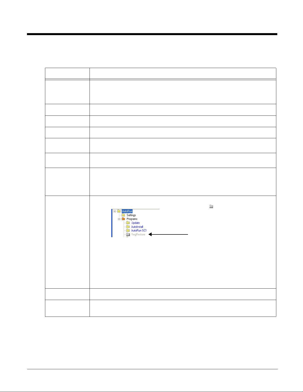
Autorun ................................................................................................................................ 6-1
Autorun.exm File............................................................................................................6-1
Programs Section and the Launch Sequence ...............................................................6-1
Enabling and Disabling Sections ...................................................................................6-1
Programs’ Subsections.................................................................................................. 6-1
Editing the Autorun.exm File..........................................................................................6-2
Adding a Program Subsection ....................................................................................... 6-2
Copying a File................................................................................................................ 6-2
Start Options.................................................................................................................. 6-2
Applying Startup Options to the Autorun.exm File......................................................... 6-3
AutoInstall............................................................................................................................ 6-4
Program Install Locations ..............................................................................................6-4
AutoInstall.exm .............................................................................................................. 6-4
Command Line Arguments............................................................................................ 6-4
Chapter 7 - DeviceConfig
Overview.............................................................................................................................. 7-1
DeviceConfig.exm File......................................................................................................... 7-1
Enabling DeviceConfig Functionality .............................................................................7-1
Autorun .......................................................................................................................... 7-1
Bar Code Delivery..........................................................................................................7-1
Settings in the WLAN Supplicant................................................................................... 7-1
DeviceConfig.exm Sections and Keys................................................................................. 7-1
Connections Section...................................................................................................... 7-1
System Section.............................................................................................................. 7-5
Applications Section ......................................................................................................7-6
Launching DeviceConfig.exe Manually ............................................................................... 7-6
Temporary Option for Bar Code Deployment ...................................................................... 7-6
Chapter 8 - Network Utilities
Accessing Network Utilities ................................................................................................. 8-1
Network Utilities Main Window ...........................................................................................8-1
IP Config..............................................................................................................................8-1
Displaying the Terminal’s IP Configuration....................................................................8-2
Ping .....................................................................................................................................8-2
Route ...................................................................................................................................8-3
Print ...............................................................................................................................8-3
Add ................................................................................................................................8-4
Delete ............................................................................................................................8-4
Clear .............................................................................................................................. 8-4
Backup Settings (Radio)......................................................................................................8-5
............................................................................................................................................. 8-6
Chapter 9 - Registry Power Tools
Overview.............................................................................................................................. 9-1
v
Page 6

Editing the Registry ............................................................................................................. 9-1
File Menu.......................................................................................................................9-2
Edit Menu.......................................................................................................................9-3
Importing Registry Files ................................................................................................. 9-3
Exporting Specific Registry Settings..............................................................................9-3
Backing Up the Entire Registry............................................................................................ 9-3
Restoring the Registry ................................................................................................... 9-4
RegBackup.exm ............................................................................................................9-4
Command Line Arguments..................................................................................................9-6
Registry Edit Options in EZConfig ....................................................................................... 9-6
Chapter 10 - ScanWedge
Overview............................................................................................................................ 10-1
Enabling, Disabling, and Exiting ScanWedge ................................................................... 10-1
Enabling ScanWedge .................................................................................................. 10-1
Exiting ScanWedge ..................................................................................................... 10-1
Disabling ScanWedge without Exiting the Application.................................................10-1
Modifying the ScanWedge Configuration File ................................................................... 10-1
ScanWedge.exm Sections ................................................................................................ 10-2
Data Formatting Reference Charts.................................................................................... 10-2
ASCII Conversion Chart (Code Page 1252)................................................................ 10-2
Symbology Chart .........................................................................................................10-4
Symbology Section...................................................................................................... 10-6
OCR............................................................................................................................. 10-7
VK (Virtual Key) Mapping Section ............................................................................... 10-7
Virtual Key Codes Table.............................................................................................. 10-8
Command Line Arguments........................................................................................ 10-12
Chapter 11 - EZ Pairing
Hardware Requirements.............................................................................................. 11-1
Using EZ Pairing to Establish a Connection...................................................................... 11-1
Modifying the ScanWedge Configuration File to Support EZ Pairing................................ 11-1
Accessing the EZ Pairing Menu ........................................................................................ 11-2
Menu Options ..............................................................................................................11-2
Modifying the EZ Pairing Configuration File ...................................................................... 11-2
EZPairing.exm Service Settings Section ....................................................................11-2
Command Line Arguments.......................................................................................... 11-3
Chapter 12 - Additional Power Tools
BattMon .............................................................................................................................12-1
To Enable BattMon...................................................................................................... 12-1
To Disable BattMon ..................................................................................................... 12-1
Keyboard Status ................................................................................................................ 12-1
To Enable Keyboard Status......................................................................................... 12-1
To Disable Keyboard Status........................................................................................ 12-2
vi
Page 7

NoSIP ................................................................................................................................12-2
To Enable NoSIP......................................................................................................... 12-2
To Disable NoSIP ........................................................................................................ 12-2
Reboot ...............................................................................................................................12-2
Chapter 13 - SysInfo
Overview............................................................................................................................ 13-1
Chapter 14 - EZMenu
Overview............................................................................................................................ 14-1
Creating Menu Configuration Files .................................................................................... 14-1
Modifying Menu Configuration Files .................................................................................. 14-1
Menu Configuration File Sections......................................................................................14-1
Settings........................................................................................................................ 14-1
MenuEntries.................................................................................................................14-1
Including an Exit Application Icon................................................................................ 14-1
Start Options................................................................................................................ 14-2
Programming the Terminal to Boot to an Application Window .......................................... 14-3
Chapter 15 - Printing
Overview............................................................................................................................ 15-1
BTPrint......................................................................................................................... 15-1
Print Demo................................................................................................................... 15-1
Chapter 16 - Customer Support
Technical Assistance.........................................................................................................16-1
vii
Page 8

viii
Page 9
1
Introduction
Dolphin Power Tools Overview
Note: Screen captures and icons in this user’s guide may differ from what appears on your device.
Power Tools are used to create custom launch menus and to control your application environment. Once you have created a
custom environment, the terminal displays only the applications you wish the user to see. Dolphin™ Power Tools are installed
on every Dolphin terminal. Different versions of Power Tools apply to different Dolphin terminals depending on the model or
operating system.
Software Requirements
Dolphin Terminal
Dolphin Power Tools 8.x is designed to work with Microsoft® Windows® Embedded Handheld 6.x.
Workstation (PC)
The Power Tools installer and the workstation version of EZConfig Editor are designed to work with the following operating systems and applications:
• Microsoft Windows XP
• Microsoft Windows 2000
• Microsoft Windows NT
• Microsoft Windows Vista®
• Microsoft Windows 7
• Microsoft Windows 8
• Microsoft .NET Framework 2.0
• Microsoft ActiveSync® (version 4.5 or higher)
• Microsoft Windows Mobile Device Center
Power Tools Main Window
Tap Start > Power Tools to access the Power Tools main window. The content of the window varies by Dolphin
model. To modify how the content is displayed, tap Menu > View, and then select either Small Icon, Large Icon, List, or Detail.
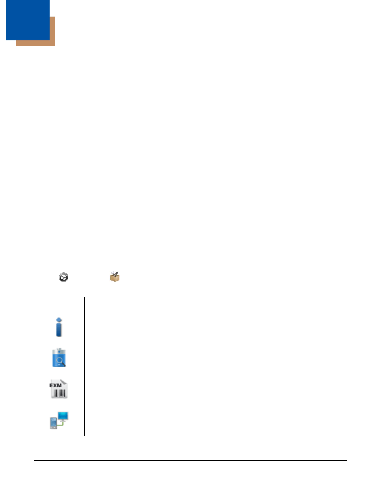
Icon Description Page
SysInfo displays system information including firmware versions, DLL versions, system
parameters, network information, and radio information.
BattMon programs the LEDs on the terminal to monitor battery power.
Note: BattMon is model dependent and may not be present on your device. Refer to the
terminal User’s Guide for battery status indicators specific to your Dolphin model.
EZConfig Utilities provides access to EZConfig Client, EZConfig Editor, and a series of
EXM configuration files.
EZ Pairing connects the terminal to a ring scanner using Bluetooth wireless technology.
Note: EZ Pairing is model dependent and may not be present on your device.
11-3
11-1
3-1
11-1
1 - 1
Page 10
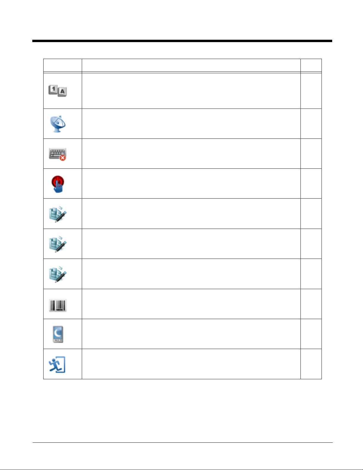
Icon Description Page
Keyboard Status places an icon on the status/notification bar at the top of the screen that
indicates the alpha-numeric status of the keyboard.
Note: Keyboard Status is model dependent and may not be present on your device. Refer
to the terminal User’s Guide for keyboard information specific to your Dolphin model.
Network Utilities provides access to the Network Utilities (i.e., IP Config, Ping, Route,
Backup Settings).
NoSIP turns off the Soft Input Panel (SIP) in every application window. 11-2
Reboot performs a reboot. 11-2
RegBackup backs up the registry. 9-3
RegRestore loads the RegBackup file. 9-4
11-1
8-1
RegEdit allows you to edit the registry and import and export registry keys. 9-1
ScanWedge allows you to send bar code data to your application. 10-1
Suspend places the terminal in Suspend mode until the Power button is pressed. 11-3
Exit Power Tools.
About the EZMenu Tool
EZMenu is an additional Power Tool that does not appear in the main window. EZMenu formats application windows to display and launch software programs on the terminal. For further information, see EZMenu beginning on page 14-1.
1 - 2
Page 11

Upgrading the Power Tools
!
Upgrades for the Power Tools on the Dolphin terminal come in the form of an executable file that installs the upgrade files onto a
workstation (PC). Once the workstation installation is complete, transfer the appropriate upgrade files to the Dolphin terminal to
upgrade the Power Tools.
Upgrades are available from Customer Support (see page 16-1) or www.honeywellaidc.com.
Note: An active Microsoft
workstation and the Dolphin terminal is required to upgrade your Power Tools software.
ActiveSync, Windows Mobile Device Center or Windows Phone app connection between a host
File Storage Locations
Two folders or paths are used to denote where your files are stored. One path is for permanent storage( \IPSM\Honeywell )
and one is for active files ( \Honeywell ).
\IPSM\Honeywell
The IPSM folder is the only partition on the terminal that persists across a kernel upgrade (*.UPG file extension).
During a kernel upgrade, files are automatically copied from the \IPSM\Honeywell folder and then installed in the
\Honeywell (root file system) folder as part of the upgrade process.
\IPSM\Honeywell\AutoInstall
The files in the IPSM\Honeywell\AutoInstall folder are only installed when a factory reset or kernel upgrade
occurs. Once the files are installed, they persist through hard and soft resets. If a file is added to the folder and a
hard or soft reset is performed, it will have no effect.
\Honeywell
The Honeywell partition or root file system partition is persistent over a hard reset, soft reset, and the removal of the
battery pack or the removal of AC power. However, during a kernel upgrade, the root file system is reformatted so all
data in the folder is deleted and replaced by any files in the \IPSM\Honeywell folder as part of the upgrade process.
To prevent data loss, back up all user data to an SD card or external memory device before performing an
upgrade.
\Honeywell\AutoInstall
If you run a CAB file from within the \Honeywell\AutoInstall (user store) folder, after the program has been
installed, the CAB file will be deleted from the User Store but the program remains installed through all successive
Hard and Soft resets.
If you want the program to be part of the Autoinstall that occurs after a factory reset or software upgrade, paste the
program file(s) in both the \IPSM\Honeywell\Autoinstall folder and the \Honeywell\Autoinstall.
1 - 3
Page 12

1 - 4
Page 13
2
EZConfig Utilities
Overview
EZConfig Utilities is made up of the EZConfig Editor, the EZConfig Client, and a series of EXM files.
EZConfig Editor is the tool used to open and edit EXM files. EXM files are the building blocks for creating the Power Tools
screens you see on your terminal. Some EXM files (e.g., AutoInstall, Autorun, and DeviceConfig) are used to display and run
your applications. Other EXM files are used to build your own customized screens and applications for the Dolphin terminal.
There are two versions of the EZConfig Editor. One that runs on the Dolphin terminal, and one that can run on your workstation
(PC). The EZConfig Editor that runs on your workstation is also capable of generating configuration bar codes from EXM files.
EZConfig Client decodes the bar codes generated by the workstation EZConfig Editor.
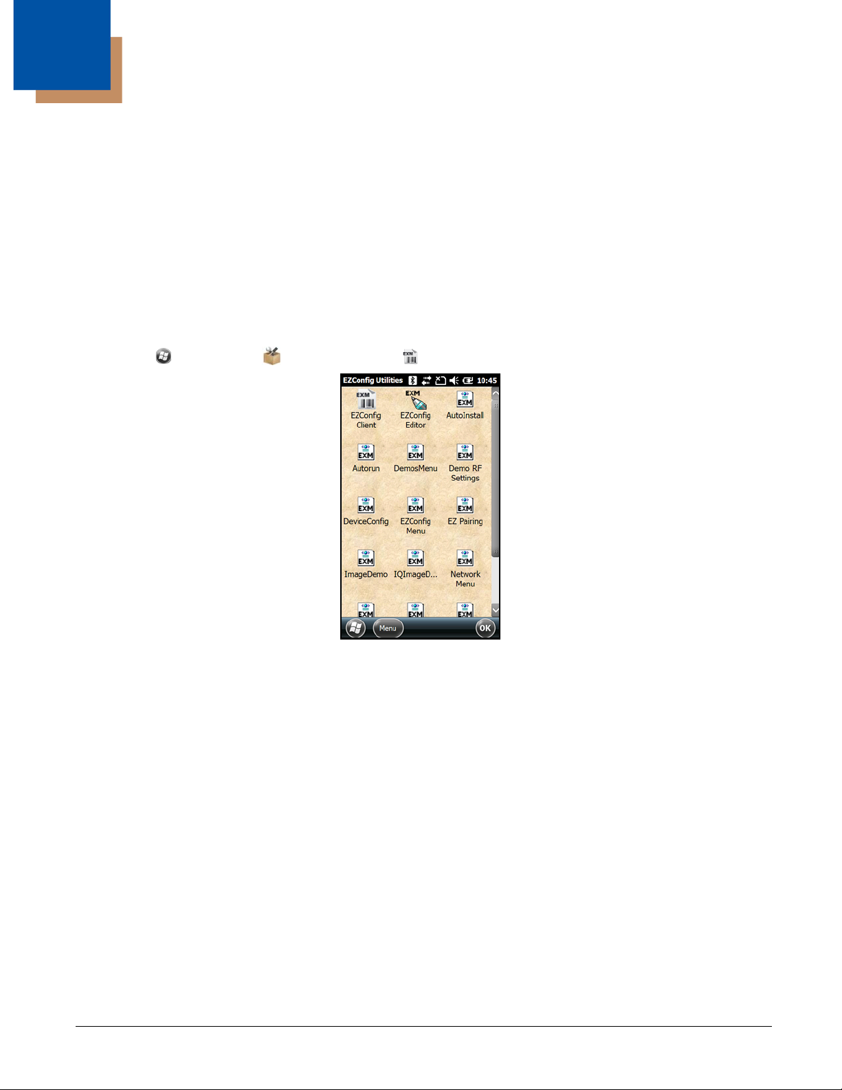
Accessing the EZConfig Utilities on the Terminal
Tap Start > Power Tools > EZConfig Utilities .
EZConfig Editor
You can use the EZConfig Editor tool to create and edit configuration files in the EXM file format for Dolphin terminals. There are
two versions of the EZConfig Editor: one for the Dolphin terminal, and one for your workstation (PC).
Workstation EZConfig Editor
The workstation editor is used to:
• Create and modify EXM files that are transferred to the Dolphin terminal.
• Generate bar codes from EXM files.
For details about the workstation editor, see EZConfig Editor on the Workstation (PC), beginning on page 4-1.
Terminal EZConfig Editor
The terminal editor is used to modify and save EXM files right on the terminal.
For details about the terminal editor, see EZConfig Editor on the Dolphin Terminal, beginning on page 3-1.
2 - 1
Page 14

EZConfig Client
You can use the EZConfig Client tool to scan and decode bar codes generated by EZConfig Editor on the workstation.
For details on scanning configuration bar codes, see EZConfig Client beginning on page 5-1.
EXM Files
The EXM file format is an XML format customized for Dolphin terminals that is comprised of sections that may include child
sections and keys. Keys contain the values that configure the terminal. The EXM file format supports a multi-level, hierarchical,
tree structure. The terminal reads the highest-level section first and then reads the key values in each section. EXM files replace
INI files for Power Tools and terminal configuration settings. If both an INI file and an EXM file are present for the same
application, a warning message displays at startup and the terminal uses the EXM. Remove the INI file from the terminal to
avoid the warning message.
EXM File Descriptions
Icon Name (File Name) Description Page
AutoInstall
(AutoInstall.exm)
Autorun
(Autorun.exm)
CameraDemo.exm
DemosMenu
(DemosMenu.exm)
Demo RF Settings.exm
(DemoRfSettings.exm)
DeviceConfig
(DeviceConfig.exm)
EZConfig Menu
(EZConfigMenu.exm)
EZ Pairing
(EZPairing.exm)
ImageDemo
(ImageDemo.exe.config.exm)
Installs cab files in the AutoInstall folder, ensuring they persist
through hard resets.
Specifies the software applications to be launched after each hard
reset.
Specifies the configuration settings for the Camera Demo.
Specifies the menu for the Honeywell Demos window.
Specifies the IP Address and TCP Port used by the Imaging Demo,
Scan Demo, IQ Imaging Demo and the Signature Capture Demo.
Contains terminal configuration settings. 7-1
Specifies the menu for the Honeywell EZConfig Utilities window.
Specifies the configuration settings for EZ Pairing. 11-2
Specifies the configuration settings for the Imaging Demo.
6-4
6-1
ImagingProfiles.exm
IQImageDemo
(IQImageDemo.exe.config.exm)
Network Menu
(NetworkMenu.exm)
2 - 2
Specifies imager configuration profile used for custom application
development. For detailed information, refer to the Honeywell SDK for
Windows Embedded Handheld available for download from
www.honeywellaidc.com.
Specifies the configuration settings for the IQ Imaging Demo.
Specifies the menu for the Honeywell Network Utilities window.
Page 15

Icon Name (File Name) Description Page
Power Tools Menu
(PowerToolsMenu.exm)
PrintDemo Menu
(PrintDemo Menu.exm)
RegBackup
(RegBackup.exm)
Scandemo
(ScanDemo.exe.config.exm)
Scanwedge
(ScanWedge.exm)
SignatureCapture.exm
Specifies the menu for the Honeywell Power Tools window.
Specifies the menu for the Print Demo window.
Specifies the exclusion or inclusion of registry key sections and
values during an export.
Specifies the configuration settings for the Scan Demo.
Sends data from the decoder or serial port to the foreground
application as keystrokes.
Specifies the configuration settings for the Signature Capture demo.
9-1
10-1
2 - 3
Page 16

2 - 4
Page 17
3
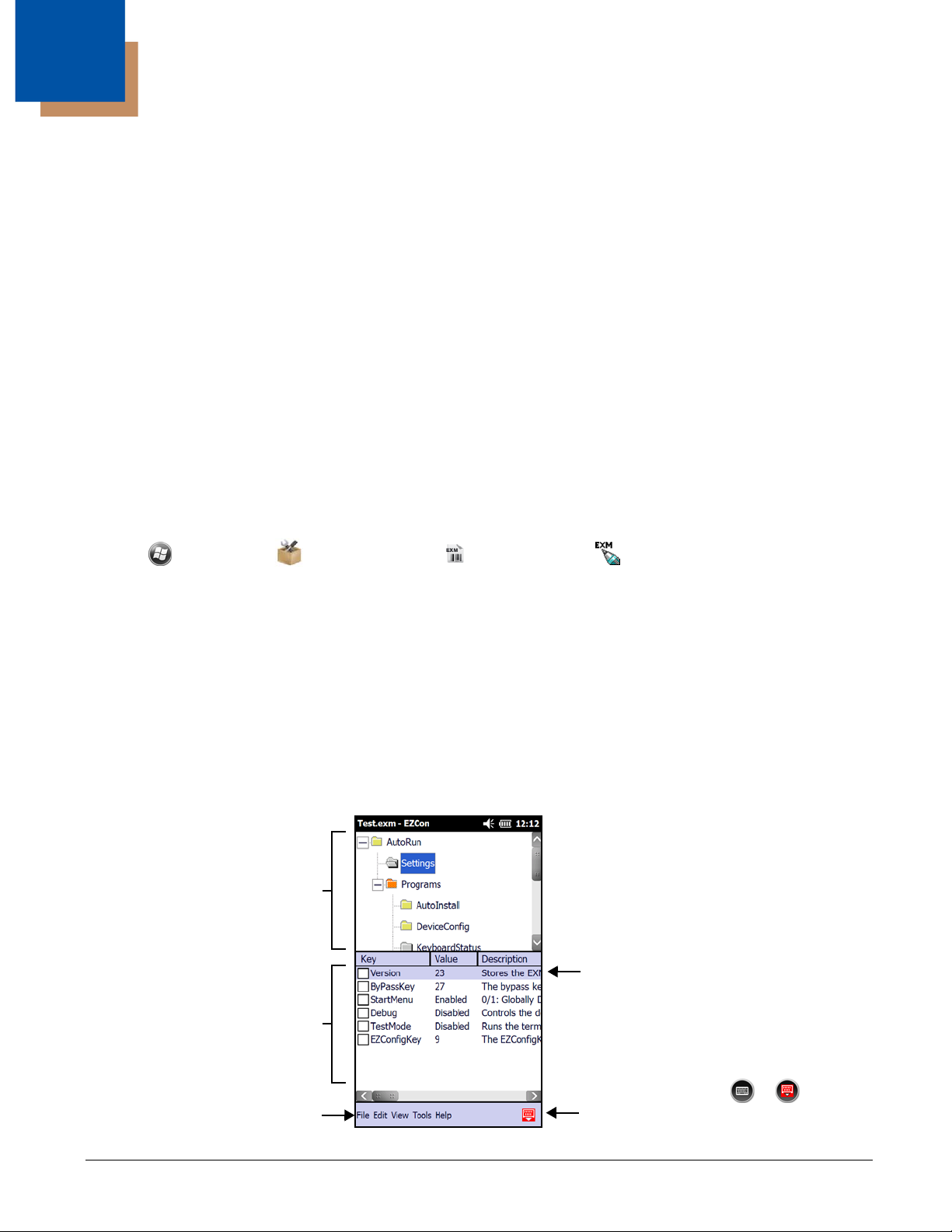
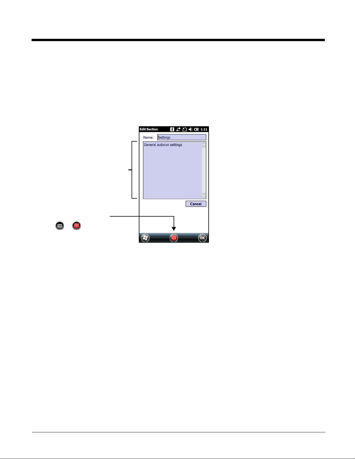
Swipe left to view the full description for
the key.
Sections
Keys
Tap the keyboard icon, or to turn
the virtual keyboard display on or off.
Menu Bar
EZConfig Editor on the Dolphin Terminal
Overview
EZConfig Editor creates, edits, and manages EXM files for Dolphin terminals. There are two versions of the EZConfig Editor:
one for the Dolphin terminal and one for the workstation. In the workstation editor, EXM files are edited, saved, and then
transferred to the Dolphin terminal. In the terminal editor, EXM files are edited and saved right on the terminal.
This chapter details the terminal version of the EZConfig Editor. For information about using the workstation version of the
EZConfig Editor, see EZConfig Editor on the Workstation (PC) beginning on page 4-1.
EXM File Structure
The EXM file format supports a multi-level, hierarchical, tree structure. The terminal reads the highest level section first and
then reads the key values in each child section. The key values configure the terminal. EXM files replace INI files for Power
Tools and terminal configuration settings. If both an INI file and an EXM file are present for the same application, the terminal defaults to the EXM file and a warning message is displayed at startup.
There are two types of configuration files in the EXM file format:
• Configuration Documents program and configure the terminal. See Configuration Documents on page 4-10.
• Registry Documents update and modify the registry. See Registry Documents on page 4-11.
Opening the EZConfig Editor on the Terminal
Tap Start > Power Tools > EZConfig Utilities > EZConfig Editor .
Opening EXM Files
To open an EXM file, do one of the following:
• Open EZConfig Utilities and tap once on the EXM file.
• Open the EZConfig Editor on the terminal and select File > Open. Browse to the file location and tap once on the EXM file.
• Open File Explorer on the terminal, browse to the file location and then tap once on the EXM file.
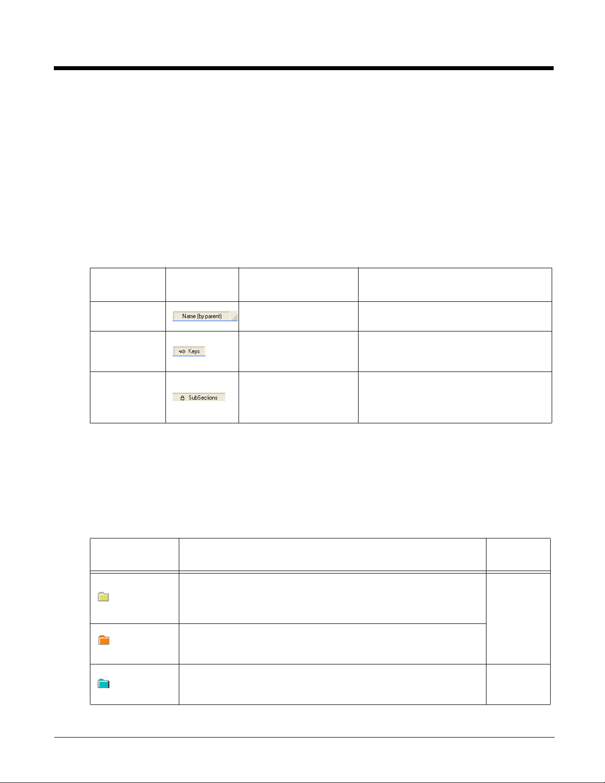
Viewing the EXM File Structure in the EZConfig Editor
Sections appear in the top half of the editor window. Select the + sign next to a section folder to view any associated child
sections. If a section folder is gray, the section is disabled. Keys appear in the bottom half of the window when a section is
selected. When a key is enabled for editing the value, the box contains a check mark. Menu selections are displayed at the
bottom of the screen.
3 - 1
Page 18

Menu Options
The lock icon means the section’s
subsections are locked.
The key icon means that the
section’s keys are locked.
File Menu
Menu Item Description
New
Creates a new document. There are two options:
• Config Doc - Creates a configuration file.
See Configuration Documents (page 4-10).
• Registry Doc - Creates a registry file in the EXM file format.
See Registry Documents (page 4-11).
Open
Save
Save As
Properties
Exit
Opens an EXM file.
Saves the open file to the location you select on the terminal. This option is disabled for
new and imported files.
Saves the open file with a new name to the location you select on the terminal.
Associates the EXM file with an application on the terminal. See Registry Documents on
page 4-11.
Closes EZConfig Editor.
Edit Menu
For editing options, see Editing Sections and Keys, beginning on page 3-3.
View Menu
Menu Item Description
Shows or hides the icons indicating if a subsection or key is locked.
Show Locks
For additional information on locks on subsections and keys, see Status Bar on page 4-4.
Tools Menu
Menu Item Description
Launch Associated App
Simplify Document
Note: You cannot undo
this action!
Warm Boot
3 - 2
For information on this item menu, see Launching on page 3-4.
Reduces the EXM file size by permanently removing:
• Disabled sections and keys
• Descriptions
Reboots the terminal.
Page 19
Editing Sections and Keys
Tap the keyboard icon,
or to turn the virtual
keyboard display on or off.
Description Field
Modifying Section Name and Description
You can only edit the name and description of a section if it is unlocked or enabled. To edit a section name or description:
1. Access the Edit Section window by doing one of the following:
• Select the section and tap Edit > Modify.
• Tap and hold on the section name, and then select Modify from the Edit menu.
2. Tap inside the Name or description fields to edit the text.
3. Tap OK or Enter on the virtual keyboard to save your changes. To close without saving your changes, tap Cancel.
Modifying a Key Name, Value, or Description
You can only edit the name and description of a section if it is unlocked or enabled. To edit a key name, value, or description:
1. Access the Edit Key window by doing one of the following:
• Select the key and then tap Edit > Modify.
• Double-tap the key.
• Tap and hold on the key name, and then select Modify from the Edit menu.
2. Tap inside the Name, Value, or Description fields to edit the text.
3. Tap OK or Enter on the virtual keyboard to save your changes. To discard your changes, tap Cancel.
Note: You cannot edit the key name or description if the key is locked.
Moving a Section or Key
To move a section or key, use the Cut, Copy, Past, or Paste as Child commands on the Edit menu. Drag and drop is not
supported.
Note: By default, the Paste function pastes sections at the same level they were cut.
Enabling a Section
Sections are enabled by default. If a section was previously disabled, you can re-enable by selecting Enable from the Edit
menu. You can enable a child section only if its parent section is enabled.
3 - 3
Page 20

Disabling a Section
To disable a section and all of its keys, select Disable All from the Edit menu. Disabled sections remain in the file and are
indicated with a gray folder. If you disable a section that has child sections, all of its child sections (and the child section
keys) are disabled automatically. The child section folders are also change to gray to indicate they are disabled.
When reading the EXM file, the terminal behaves as though disabled sections are not there and moves on to read the next
enabled section.
A disabled section can be removed from the EXM file permanently by using the Delete option on the Edit menu when the
section is selected. If you want all disabled section permanently removed, use the Simplify Document option on the Tools
menu.
Adding a Section or Child Section
Select Insert Section from the Edit menu.
Select Append Child Section from the Edit menu to insert a new child section to the selected section. The new child section is inserted below the previous section.
Associating an Application to an EXM File
Launching
To launch an application associated to an EXM file, open the EXM file in EZConfig editor, and then tap
Tool s > Launch Associated App. The open EXM file automatically saves, and the associated application launches while
the EXM file remains open.
Viewing
To see if an open EXM file has an associated application, open the EXM file in EZ Config editor, and tap File > Properties.
The Path field contains the launch location of the application and the Args field contains any command line arguments to
execute when the application launches.
Adding or Editing
To add or edit an application association to an EXM file:
1. Open the EXM file in EZ Config editor on the terminal.
2. Tap File > Properties.
3. In the Path field, enter or edit the location of the application executable (.exe) file on the terminal
When an application is entered in the Path field, the following occurs:
• the command line /exm %filename appears in the Args (argument) field.
• the Execute box is automatically selected.
Execute must be selected for Configuration documents. You can deselect Execute for registry documents; however,
EZConfig Client cannot update the registry unless Execute is selected. For more information, see Creating Registry
Documents (page 4-12).
4. In the Args field, enter additional command line arguments next to the command line/exm %filename. For more
information, see Command Line Arguments.
5. If the EXM should wait until the associated application has exited before continuing, select Wait Until Finished.
6. Tap OK.
7. To save your changes to the EXM file, tap File > Save or Save As.
.
3 - 4
Page 21

Command Line Arguments
/exm %filename executes the EXM file; this is the default entry
/q quiet mode
/s full screen
/o no menu
/e exit if first scan fails to deliver a valid bar code
/u accept (decode) unsecured bar codes
3 - 5
Page 22

3 - 6
Page 23

4
EZConfig Editor on the Workstation (PC)
Overview
EZConfig Editor creates, edits, and manages EXM files for Dolphin terminals. There are two versions of the EZConfig Editor:
one for the Dolphin terminal and one for the workstation. In the workstation editor, EXM files are edited, saved, and then transferred to the Dolphin terminal. In the terminal editor, EXM files are edited and saved right on the terminal.
This chapter details the workstation (PC) version of the EZConfig Editor. For information about using the terminal version of the
EZConfig Editor, see EZConfig Editor on the Dolphin Terminal beginning on page 3-1.
EXM File Structure
The EXM file format supports a multi-level, hierarchical, tree structure. The terminal reads the highest level section first and
then reads the key values in each child section. The key values configure the terminal. EXM files replace INI files for Power
Tools and terminal configuration settings. If both an INI file and an EXM file are present for the same application, the terminal defaults to the EXM file and a warning message is displayed at startup.
There are two types of configuration files in the EXM file format:
• Configuration Documents program and configure the terminal. See Configuration Documents on page 4-10.
• Registry Documents update and modify the registry. See Registry Documents on page 4-11.
Installing EZConfig for Mobility on the Workstation
1. Access the Honeywell web site at www.honeywellaidc.com, and then locate the product page for your Dolphin model.
2. Select the Software tab.
3. Under the Tools and Utilities heading, click on the listing for Honeywell EZConfig for Mobility Setup.
4. Follow the security directions as prompted on the screen and then click on Download.
5. When prompted, select Save, and then select a location on your workstation (e.g., your desktop).
6. Double click on the downloaded EZConfig for Mobility Setup.zip file.
7. Double click on the Setup.exe file. Select OK.
8. Follow the screen prompts to install the EZConfig for Mobility program.
Upgrades
Upgrades for EZConfig Editor on the workstation are available from Customer Support (see page 16-1) or
www.honeywellaidc.com.
Opening the EZConfig Editor on the Workstation
After you complete the software installation, EZConfig Editor is available on the workstation from the Start menu.
Click Start > All Programs > Honeywell > EZConfig for Mobility > EZConfig for Mobility to open the EZConfig Editor.
Menus and Toolbar Options
When you open the EZConfig Editor, menu selections are displayed across the top of the screen, and icons for actions are
shown below the menu bar.
Note: Some menu selections and Toolbar icons will be grayed out until an EXM file is opened.
4 - 1
Page 24

File Menu
The lock icon means the section’s
subsections are locked.
The key icon means that the
section’s keys are locked.
Menu Item Description
Creates a new document. There are two options:
• Configuration Document - Creates a configuration file in the EXM file format.
New
• Registry Document - Creates a registry file in the EXM file format.
See Configuration Documents (page 4-10).
See Registry Documents (page 4-11).
Open
Open Recent
Open from Device
Save
Save As
Save to Device As
Create EZConfig
Bar Code
Properties
Exit
Opens an EXM file located on the workstation.
Opens an EXM file selected from a list of recent files opened.
Opens an EXM file located on the terminal. The location of the file appears on the title bar with
the word “[Remote]” to identify that the open file is located on the terminal.
Note: This option requires an active connection between the workstation and the terminal
(e.g., ActiveSync, Windows Device Mobile).
Saves the open file to the location you select on the workstation.
This option is disabled for new and imported files; use the Save As option instead.
Saves the open file with a new name to the location you select on the workstation.
Saves an open file to the Dolphin terminal.
Note: This option requires an active connection between the workstation and the terminal.
Embeds the open EXM file in an Aztec bar code.
Associates the EXM file with an application on the terminal.
See Registry Documents on page 4-11.
Closes EZConfig Editor.
Edit Menu
For Section Edit menu options, see Working with Sections on page 4-4.
For Key Edit menu options, see Working with Keys on page 4-7.
View Menu
Menu Item Description
Show Locks
4 - 2
Shows or hides the icons that indicate if a subsection or key has been locked against editing.
For additional information on locks on subsections and keys, see Status Bar on page 4-4.
Page 25
Tools Menu
Menu Item Description
Simplifies the EXM file, which makes it smaller. Simplifying a document permanently
removes:
Simplify Document
Note: You cannot
undo this
action!
Because the following menu items execute commands on the terminal, there must be an active connection between the
workstation and the terminal (e.g., ActiveSync, Windows Mobile Device Center, or Windows Phone app).
Launch Associated
App
• disabled sections and keys.
• descriptions.
• bar code settings.
Note: When you create a bar code, you can simplify the file embedded in the bar code without
affecting the open EXM file. This reduces the size of the bar code package yet keeps
the disabled sections, descriptions, and bar code settings in the open EXM file for future
reference.
If the open EXM file is associated with an application on the terminal, this item appears active
on the Tools menu and when selected launches the associated application on the terminal.
You would use this option after saving the EXM file to the terminal; see Saving to the Device
on page 4-9.
Warm Boot
Factory Reset
Device
Soft Reset (Warm Reboot) the terminal.
Factory Reset the terminal.
Opening EXM Files
EZConfig Editor opens EXM files either stored on the workstation or on the Dolphin terminal if an active connection has been
established between the terminal and workstation (e.g., ActiveSync, Windows Mobile Device Center, or Windows Phone app).
Opening EXM Files Stored on the Workstation
Click File > Open or the Open toolbar icon and select the EXM file.
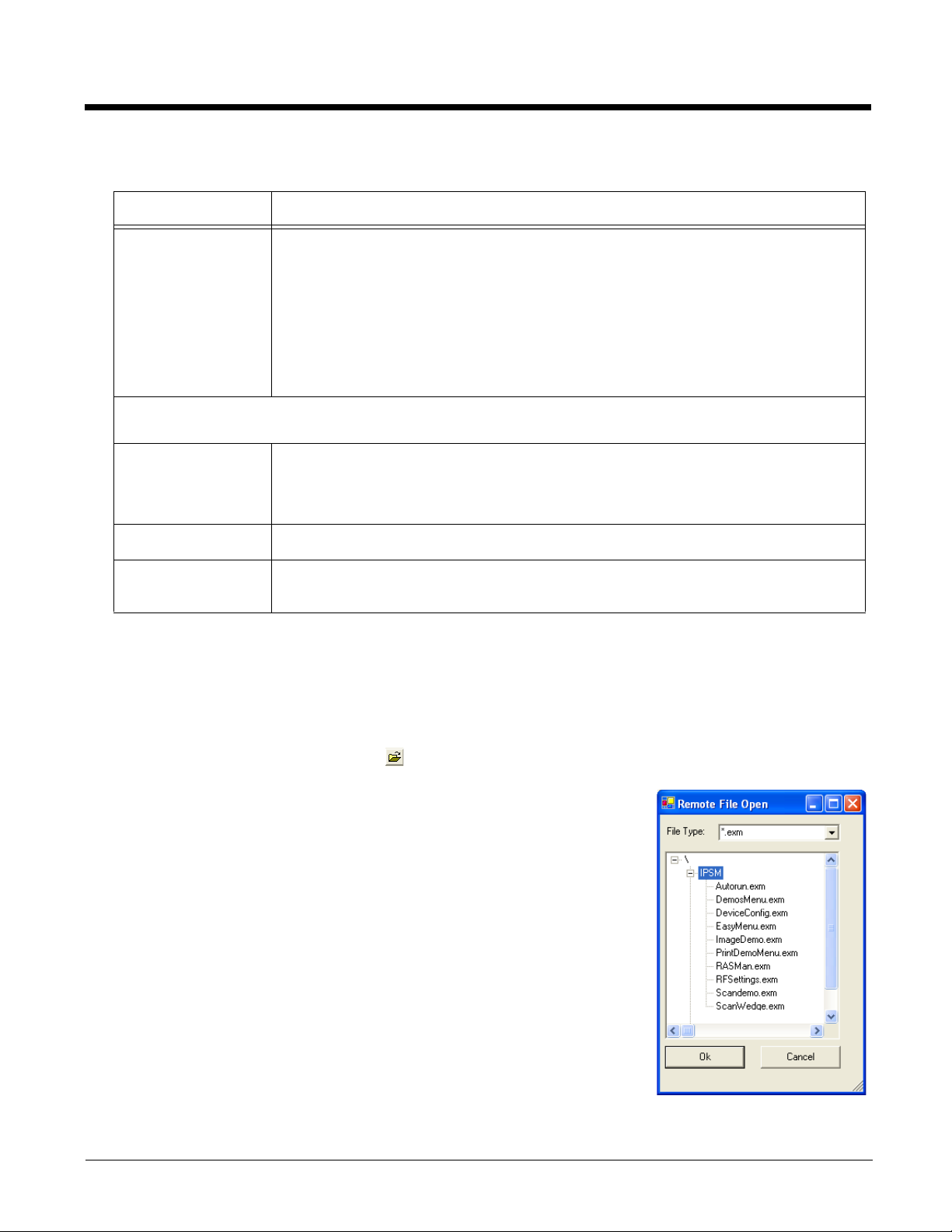
Opening Remote EXM Files
To open and edit an EXM file located on the Dolphin terminal using EZConfig
Editor on the workstation:
1. Establish an active connection between the terminal and workstation.
2. Open EZConfig Editor on the workstation.
3. Click File > Open From Device.
4. Select the file, and then OK.
Note: You can also open EXM files in the editor on the terminal. See EZConfig
Editor on the Dolphin Terminal beginning on page 3-1.
4 - 3
Page 26
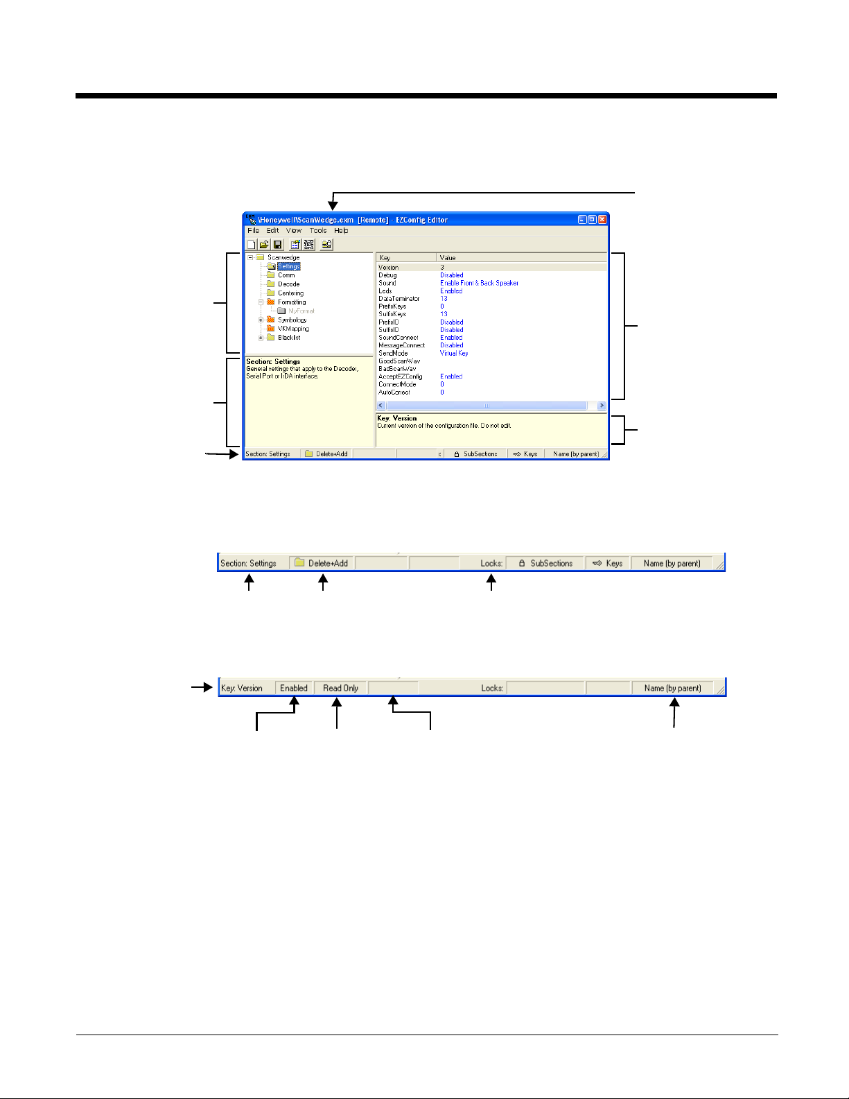
Working with Open EXM Files
Displays the root node
and sections.
Select a section and the
details appear in the other
portions of the window.
The folders appear in
different colors to indicate
their status.
Displays the section
name and description.
Displays the keys in the
selected section.
Text that appears in blue
can be edited.
Displays the selected
key’s name and
description.
Displays the file name.
If the file is on the
terminal, the title bar
displays the remote path.
Status Bar
Section
Name
Merge
Mode
Locks on subsections and keys
Key Name
Enabled or
Disabled
Read Only Encrypted Key locked by section
When you open an EXM file, EZConfig Editor displays the content in four different sections of the window.
Status Bar
The Status Bar appears at the bottom of the window and displays information about selected sections and keys.
Selected Section
Working with Sections
The EXM file format supports a multi-level tree structure. The section tree appears in the top left quadrant of the window
when a file is open. When selected, the root node identifies the EXM file and includes the word “Root” in the description displayed in the lower left quadrant.
Sections have a name and description and contain keys that appear in the upper right quadrant when you select the section
name. Select a section by clicking on it. You can select only one section at a time.
4 - 4
See Section Locks on page 4-6.
Selected Key
See Key Types on page 4-9.
Page 27
Edit Menu Options
Select a section and click Edit to see the available options.
Menu Item Description
Allows you to rename the section name. You can also double click on the description to bring
Rename
up the Modify screen.
Note: You cannot modify the name if the section is locked or disabled; see Section Locks
(page 4-6).
Cut
Copy
Paste
Paste as Child
Delete
Enable
Disable All
Cuts a selected section.
Copies a selected section.
Pastes the section that was just cut or copied at the same level as the selected section.
Pastes the section that was just cut or copied as a child of the selected section.
Note: You can cut, copy and paste sections within an EXM file or across EXM files.
Deletes a selected section.
Note: Because you cannot undo a delete, consider disabling rather than deleting.
Sections are enabled by default. This menu item enables sections that were previously
disabled. You can enable a section only if its parent section is enabled.
To enable all the keys inside a section you are enabling, SHIFT + right-click and select
Enable All.
Sections are enabled by default. This menu item disables a selected section and all of its
keys. Disabled sections remain in the file with a gray folder .
If you disable a section that has child sections, all of its child sections (and the child section
keys) are disabled automatically. The child section folders are also in gray.
When reading the EXM file, the terminal behaves as though disabled sections are not there
and moves on to read the next enabled section.
Disabled sections can be removed from the EXM file permanently using the Simplify
Document (see page 4-3) option. If you want to keep disabled sections in the EXM file on the
workstation but not in the file deployed to the terminal, use the Simplified option (see page 4-
3).
Insert Section
Append Child
Section
This menu item inserts a new section.
This menu item adds a new child section to a selected section. The new child section is
inserted below the previous section.
Moving Sections
To move sections within an EXM file, use the drag and drop method. By default, sections are dropped at the same level
in the tree.
For additional functionality when dragging and dropping, hold:
• ALT to drop a section as a child section.
4 - 5
Page 28
• CTRL to copy a section and drop the copy at the same level in the tree.
• CTRL + ALT to copy a section and drop the copy as a child section.
Note: You can select only one section at a time; you cannot use SHIFT+Click or CTRL+Click to select more than one
section.
To move sections between EXM files, open two instances of EZConfig Editor and drag and drop sections between the
session windows. When dragging, a copy of the section is dragged to the new file. When dropping, drop the section
directly on top of the section where you want the child section to appear.
Note: To drop the first section into a new file, press and hold the ALT key and drop the section on the root node. All
sections must be child sections of the root node.
Section Locks
There are different types of locks on sections. The status bar indicates what type of lock is applied to a selected section.
Lock Type
Name Lock
Key Lock
Subsection
Lock
Note: All locks are applied to each individual section and are not recursive. Only text that appears in blue can be
modified.
Status Bar
Indicator
Description Effect
The section name is
locked.
All keys are locked. Key Names and Descriptions cannot be
All immediate subsections
are locked.
Section Name and Description cannot be
modified.
modified. Keys cannot be added, moved, or
deleted within the section.
Immediate subsection Names and
Descriptions cannot be modified. Immediate
subsections cannot be added, moved, or
deleted.
Section-Level Merge Modes
EXM files ship with section-level merge modes already defined according to section content. Merge modes determine
how section information is handled when an updated EXM file is deployed to the terminal where an existing version of
that EXM file is stored.
Merge modes are indicated by folder icons and in the Status bar.
Mode Description
Merge
Effect
4 - 6
Delete + Add
Disable +
Add
Add Only
Deletes non-common children elements (i.e., subsections, and keys) in the
target file, then adds the new information from the exm file. Basically, the
new section replaces the old section.
This is the default merge mode for new sections.
Disables non-common children elements (i.e., subsections, and keys) in the
target file, then adds the new information from the bar code.
Note: Disabled sections and keys end up as disabled in the target file.
Adds new information (sections and keys) to the existing section. If this is a
brand new section, the new section is added to the existing EXM file.
Note: Disabled sections are not modified in the target file.
Exclusive
Inclusive
Page 29
To change section-level merge modes, select a section and right click.
The same options
appear on both
menus.
The folder colors change immediately after selection.
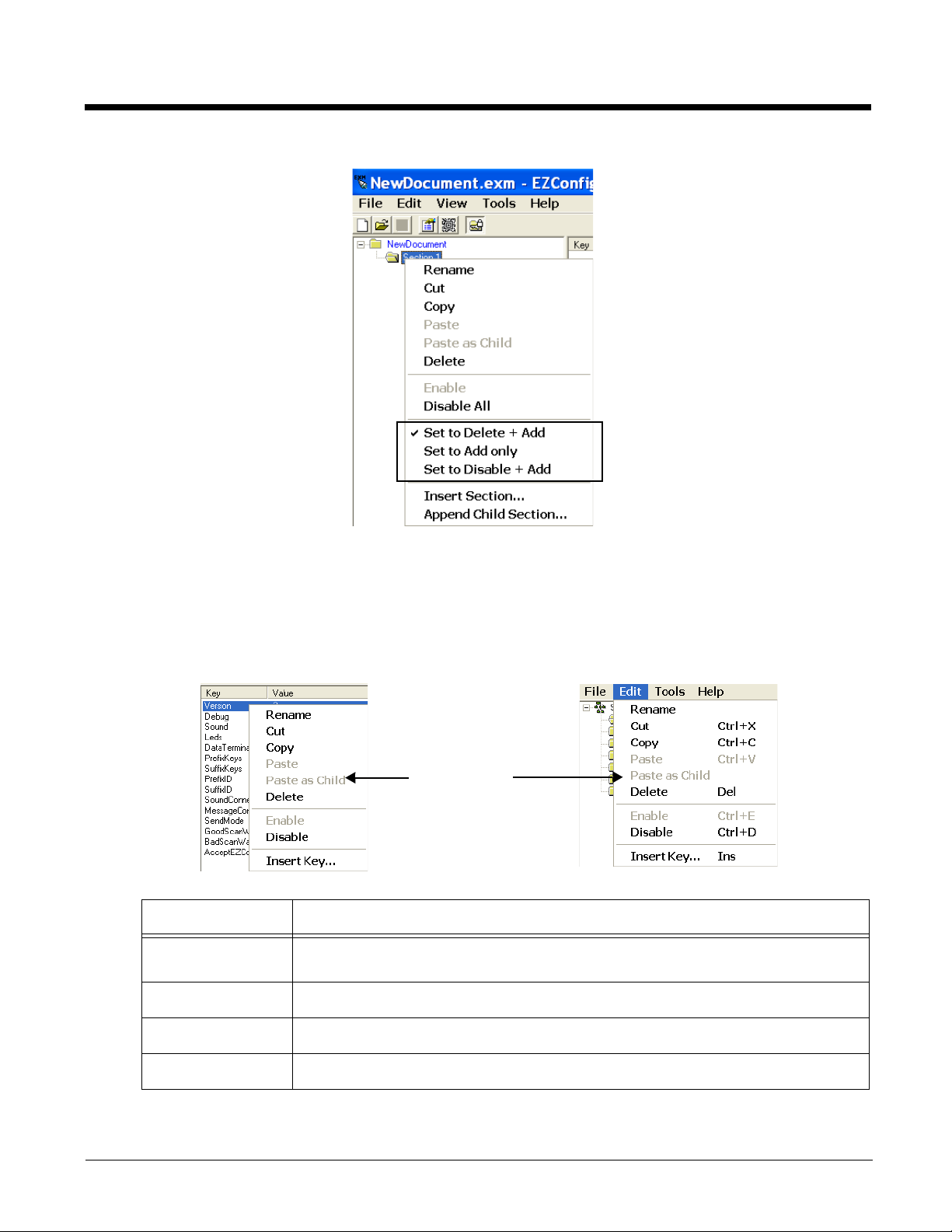
Working with Keys
Keys have a Name, a Description, and a Value and reside inside sections. For specific key values, consult the chapters of
this User’s Guide that describe the EXM file you are editing.
Edit Menu Options
Select a key and right-click or click Edit to see the available options.
Menu Item Description
Rename
Cut
Copy
Paste
Activates the key name so that you can rename the key. Rename is disabled if the key is
locked or disabled; see Key Types (page 4-9).
Cuts a selected key.
Copies a selected key.
Disabled; keys can be pasted only as children of a section.
4 - 7
Page 30

Menu Item Description
Pastes the key just cut or copied in the selected section. Keys are not multi-level; all keys
Paste as Child
paste at the same level within a section.
You can cut, copy and paste keys within an EXM file or across EXM files.
Delete
Enable
Disable
Insert Key
Deletes a selected key.
Note: You cannot undo a delete; you might want to consider disabling rather than deleting.
Enables keys that were disabled. When a key is enabled, the client application can read
and apply its value. When you enable a key, make sure to specify a value for that key; do
not leave it blank.
To enable a key, its parent section must be enabled.
Disables keys.
Disabled keys have key values in black. Enabled keys have key values in blue.
The terminal does not read disabled keys and disabled keys are removed if the file is
simplified. See Simplify Document on page 4-3.
Because many key values are 1 for enable and 0 for disable, remember that disabling a key
means that the terminal behaves as if the key is not there when reading the file, NOT that
the key’s value is set to disabled. The terminal simply moves on to read the next enabled
key.
This menu item inserts a new key above the selected key.
Note: You can also press the Insert key (INS) on your keyboard.
4 - 8
Modifying Key Names
To modify key names, double-click on the key name or select Rename on the Edit menu. Type in the new name and
press ENTER or TAB.
Note: You cannot modify the description if the key is locked, see Key Types (page 4-9). Only text that appears in blue
can be modified.
Modifying Key Values
You can modify a key value only if its text appears in blue. In that case, double-click on the value or select the key and
press ENTER. Type in the new value and press ENTER or TAB to save.
Modifying Key Descriptions
Descriptions are not required to process key values but do help document the EXM file and often contain valuable
information. To modify a key’s description, click on the key, then click in the key description area. When the cursor is
active, you can type in the text.
Note: You cannot modify the description if the key is locked; see Key Types (page 4-9).
Moving Keys
To move keys within an EXM file, use the drag and drop method. Press and hold the CTRL key to drag and drop a copy
of the key to the new location.
Note: You cannot move a key if it is locked by its section.
Page 31

To move keys between EXM files, open two instances of EZConfig Editor and drag and drop keys between the windows. When you select the key and drag, a copy of the key is dragged to the new file. In the new file, drop the key in the
key area of a selected section; keys are always dropped at the same level within a section.
Key Types
When a key is selected, its properties display in the Status bar.
Lock Type
Name Lock
Read Only
Encrypted
Note: Locked and Read Only properties are not recursive. Properties are applied to each individual key. Only text that
appears in blue can be modified.
Status Bar
Indicator
Description Effect
Keys are locked by the section. • Name and Description cannot be
The key name is locked
individually.
Read-only keys cannot be
modified in any way. They
appear in red.
Key’s value appears as asterisks
(*) for added security.
modified.
• Keys cannot be added, moved, or
deleted within the section.
• Name and Description cannot be
modified.
• These keys can be moved.
• Name, Description, and Value cannot
be modified.
• Keys cannot be added, moved, or
deleted within the section.
Note: Encrypted keys are also stored
encrypted in the EXM file. If you
open the EXM file in a text editor,
you won't see the data as clear
text.
Saving to the Device
You can save EXM files directly to the terminal when there is an active connection between the terminal and the workstation
(e.g., ActiveSync, Windows Mobile Device Center, or Windows Phone app).
1. Select File > Save to the Device As.
2. From the Save Remote File window, select the location on the terminal where you want to store the file.
3. Click OK. The file is downloaded directly to the terminal via the active connection.
4 - 9
Page 32

Configuration Documents
The terminal reads
root node first.
The Description
says “Root” to
indicate that this is
the root section.
Key Value
Area
Key
Description
Area
EZConfig Editor creates configuration documents in the EXM file format to use for programming and configuring terminals.
Creating New Configuration Documents
To create new EXM files that are configuration documents, you can open an existing EXM file and save it with a new name
or create an EXM file from scratch.
1. Click File > New > Configuration Document. The root node is created and appears as the top level section. All sections must be at least one level down from the root node.
The name of the root node is always the same as the filename.
2. To create the first subsection, select the root node, right-click, and select Append Child Section.
Insert Section is disabled because you cannot insert sections at the same level as the root node.
3. Enter a Name and a Description and click OK. The name is required, the description is optional.
4. To add a new section at the same level, right-click and select Insert Section.
To add a new section one level down, right-click and select Append Child Section.
5. To add keys, select a section, right-click in the key value area, and select Append Key.
6. After the first key is added under a section, right click and select Insert Key for additional entries.
7. Input the Name of the new key then double click under the Value column heading to enter a value.
8. Right-click in the key description area to add a Description for the new key.
9. The name is required, the description is optional.
10. Continue adding sections and keys.
11. If necessary, associate this EXM file with an application; see Registry Documents (page 4-11).
12. Click File > Save As to save the file.
Note: Save is disabled so that you save the document with a name other than “NewDocument.exm.”
4 - 10
Page 33

Associating Applications
The Properties function associates an EXM file with an application on the terminal. The associated application launches
after EZConfig Client decodes the bar code containing the EXM file. While the EXM file is open, click File > Properties or
the Document Properties toolbar button .
Field Description
Path
Arguments
Execute
Enter the location of the EXE on the terminal.
Enter the command line argument you want applied when the application launches.
When an application is entered in the Path field, the following command line appears as the
argument: /exm %filename.
Enter additional command line arguments next to /exm %filename in this field.
“%filename” means that the value immediately after the “%” is variable. Type in the location and
file name where the EXM file should be deployed on the terminal. For example,
\Honeywell\deviceconfig.exm.
Command Line Arguments
/exm %filename Executes the EXM file; this is the default entry.
/q Quiet mode
/s Full screen
/o No menu
/e Exit if first scan fails to deliver a valid bar code
/u Accept (decode) unsecured bar codes
If selected, EZConfig Client launches the application after decoding the bar code. Execute is
enabled automatically when an application is entered in the Path field.
You cannot de-select Execute for configuration documents.
You can de-select Execute for registry documents, however, the registry is not updated unless
Execute is selected. For more information, see Creating Registry Documents (page 4-12).
Wait Until Finished
If selected, EZConfig Client waits until the associated application is finished processing before
finalizing.
Registry Documents
EZConfig Editor creates registry documents in the EXM file format and also opens existing REG files and converts them to the
EXM file format. EZConfig Editor cannot save registry documents in the REG file format.
4 - 11
Page 34

Creating Registry Documents
Key Value
Area
Key
Description
Area
1. In EZConfig Editor, click File > New > Registry Document.
The new document contains the three top-level sections in a registry. These sections are locked and cannot be
changed. You can add subsections to each section and then add keys to those subsections.
2. Click File > Save As.
3. Choose the name and location and click Save.
You cannot save the document as a .reg file; you must save it as an EXM file.
4. To add sections, select one of the registry levels, right-click, and select Append Child Section.
Enter the section information, and click OK.
For more information about adding sections, see Working with Sections on page 4-4.
5. To add keys to the new section, select the section, and right-click in the key value area.
For details, see Adding Registry Keys on page 4-12.
6. Continue adding sections and keys.
7. Save the file.
Adding Registry Keys
1. Select a section, right-click in the key value area and select Append Key.
Note: After the first key is added under a section, right click and select Insert Key for additional entries.
2. Input the Name of the new registry key then double click under each column heading to input the key Type and Value.
3. Right-click in the key description area of the screen to add a description for the new key.
4 - 12
Page 35

Default Application Association for Registry Documents
While a registry document is open, click File > Properties. By default, registry documents are associated with EZConfig
Client with Execute enabled.
Note: Execute must remain selected for the registry to be updated. If Execute is not selected, the registry document is
deployed, but the registry is not updated.
Updating the Registry on the Terminal
To update the terminal’s registry using an active connection between the terminal and PC:
1. Create an EXM file that is a registry document; see Creating Registry Documents on page 4-12.
2. Save the EXM to the terminal; see Saving to the Device on page 4-9.
3. On the terminal open the EZConfig Editor, open the EXM, tap Tools > Launch Associated App to update the
registry.
To update the terminal’s registry using a EZConfig bar code:
1. Create an EXM file that is a registry document; see Creating Registry Documents on page 4-12.
2. Create a bar code package from that EXM file; see Create EZConfig Bar Code, below.
3. Scan the bar code with the terminal.
Processing Registry Documents on the Terminal
After EZConfig Client updates the registry, the EXM file itself is deployed to the location entered in the Remote Path (page
4-15) field on the Bar Codes Tab.
Note: EXM files are identified with an icon.
If you do not want to store the registry EXM file on the terminal after updating the registry, select the Temporary (page 4-17)
option on the Bar Codes Tab.
Persistent Registry Documents
If you want to update the registry during every Hard Reset (Cold Reboot), create a registry document in the EXM format, save it to the terminal in the active storage folder, then perform a Hard Reset. The registry settings in the EXM file
will load during startup.
If you want to save a registry file but not load it every startup, store the registry EXM file in the permanent storage
folder where it will only be loaded if a Factory Reset or kernel upgrade is performed.
See File Storage Locations on page 1-3 for further information on active and permanent file storage locations.
Create EZConfig Bar Code
EZConfig Editor embeds EXM files in Aztec bar codes. The EZConfig Client on the terminal decodes the bar code and deploys
the data. Using bar codes quickly and easily configures Dolphin terminals without an ActiveSync or network connection to a
workstation.
4 - 13
Page 36

Document Types
EZConfig Editor produces two kinds of EXM files: Configuration Documents (page 4-10) and Registry Documents (page 4-
11). Both can be embedded in bar codes and processed by EZConfig Client on the terminal.
Note: EXM files are stamped with the time and date the moment EZConfig Editor creates the bar code.
Bar Code Type, Size and Number
EZConfig Editor creates an Aztec bar code. The amount of data in the EXM file determines how many bar codes are generated and the physical size of each bar code. More data means more bar codes and larger bar codes.
EZConfig Editor offers four ways to control how many bar codes are produced and adjust the size of each bar code:
• Set the byte size limits on how much data each bar code can contain (see page 4-16).
• Split the data across a specified number of bar codes (see page 4-15).
• Simplify the EXM file in the bar code(see page 4-15).
• Scale the bar codes on the bar code sheet (see page 4-18).
Bar Code Sheet
EZConfig Editor produces a bar code sheet that contains the generated bar codes. Bar code sheets can be printed from a
laser printer, copied to the clipboard, and saved as an HTML file. See Printing and Saving Options on page 4-18.
In addition, individual bar codes can be saved as TIF or PNG graphic files that can then be emailed and printed. See Bar
Codes Tab on page 4-15.
Generating Bar Codes
When creating a bar code, EZConfig Editor automatically encrypts and compresses the data in the EXM file. EXM files are
stamped with the time and date the moment EZConfig Editor creates the barcode.
Note: The number of bar codes produced depends on the amount of data present in the EXM file. The more data present,
the more bar codes generated. You must scan all bar codes to deploy the package!
To generate a bar code(s):
1. Click File > Create EZConfig Bar Code OR Generate Bar Code while the EXM file is open.
2. The EZconfig Bar Code Bar window opens displaying the details of the bar code package generated.
3. You can make adjustments using the options on the Bar Codes Tab (page 4-15) and the Advanced Tab (page 4-16) or
use one of the options provided to output the package.
Note: The number of bar codes produced depends on the amount of data present in the EXM file. The more data present,
the more bar codes generated. You must scan all bar codes to deploy the package!
4 - 14
Page 37

Bar Codes Tab
The Bar Codes tab previews and customizes generated bar code(s).
Field/Option Description
Indicates which bar code is displayed in the preview area; the default is “1,” the first bar code
Display
in the package. If more than one bar code was generated, you can use the up and down
arrows to scroll through the bar codes.
(___ bytes)
Remote Path
Full Contents
Simplified
# Bar codes to
generate
Displays the exact byte size of the bar code displayed in the preview area.
To ta l Package Size (page 4-18) is displayed at the bottom of the window.
The sum of bar code size is typically larger than the package size.
Type in the active storage location and filename where the EXM file should be deployed on
the terminal. For example:\Honeywell\deviceconfig.exm
Tap the browse button to navigate to the location on the terminal. An active connection
between the terminal and workstation is required (e.g., ActiveSync, Windows Mobile Device
Center, or Windows Phone app).
You may want to copy this file into permanent storage (page 1-3) if you want it to persist after
a factory reset or kernel upgrade.
Includes the full content of the EXM file in the bar code, without simplifying.
Simplifies the EXM file in the bar code, which removes disabled sections, description
information, and bar code settings (if any), which decreases the size of the bar code.
The open EXM file is not simplified.
Simplified is selected by default. The differences in total package size are displayed in the
Package Size (page 4-18) field. Individual bar code size can be seen in the Display (page 4-
15) field.
This is active only if the Always use minimum # bar codes (see page 4-16) is not selected.
When this slider is active, you can move the slider toward minimum or maximum to change
the number of bar codes generated. As you move the slider, you’ll see the number of bar
codes in the counter at the bottom of the window and you’ll notice the graphic of the bar code
in the preview area change.
Copy to Clipboard
Copies the bar code displayed in the preview area to the clipboard.
Use this option to paste the bar code into another application.
4 - 15
Page 38

Field/Option Description
Saves the bar code displayed in the preview area as a graphic file as a .png or .tiff.
Save
Save All
By default, the name of the graphic file is the same as the name of the open EXM file. You
can enter a different name when saving.
Saves all bar codes in the package as individual graphic files.
By default, the graphic files are saved with the same name as the open EXM file with a
number at the end to distinguish the individual graphic files from each other.
Print
Opens the printing window where you can select print options and print the bar code
package. For details, see Printing and Saving Options on page 4-18.
Advanced Tab
The Options tab contains settings that tell EZConfig Client how to process the EXM file on the terminal.
Field Description
4 - 16
Bar Code Options – This section determines some of the basic bar code parameters.
Max Barcode Size Set the maximum amount of data (in bytes) one bar code can contain. The lower the
number of bytes, the smaller the bar code.
On the Bar Codes tab, bar code size appears in the Display field (see page 4-15).
The total number of bar codes created as a result of the maximum bar code size limit
appears at the bottom of the Advanced window; see Bar Codes (page 4-18).
Always use
minimum # bar
codes
Use custom
password
This option is selected by default. It calibrates the data so that the minimum number of bar
codes are used. When this option is selected, the number of bar codes slider on the Bar
Codes tab is disabled.
This option enables you to password-protect the bar code you’re creating.
Select this option, then enter the password in the field provided. You will be able to see the
password when you enter it; however, you will not be able to see the password again once
you close the window because the password will be encrypted.
If you password-protect the bar code, EZConfig Client on the terminal will prompt you to
enter that same password on decoding.
Page 39

Field Description
Full screen
progress dialog
Warm boot after
finished
Deployment Options – These options determine how to deploy the EXM file on the terminal.
Merge each
section…
(Default selection)
Temporary Deploys the EXM file temporarily. The settings in the EXM file are applied, but the file does
Replacement EXM Options – This section determines how the EXM file will be deployed if there exists on the
terminal an EXM file of the same name in the same location.
Replace remote file Replaces the existing file; no section-level merge modes are applied.
This option runs the deployment progress dialog box on the terminal in full screen mode so
that the user cannot open another application while the bar codes are being deployed on
the terminal.
This option automatically launches a warm boot on the terminal after the bar code is
deployed. Use this options with EXM files that contain application information requiring a
warm boot to take effect, such as registry settings.
Deploys information according to the section-level merge mode settings; see Section-Level
Merge Modes on page 4-6.
If already exists, deploy:
Always–Select to always use the section-level merge mode settings.
Only if newer–Select to use the section-level merge mode settings only if the sections are
newer than the existing file.
not remain in the system after EZConfig Client is done.
If the terminal contains a previous EXM file with the same name, the previous EXM file is
preserved.
If already exists, deploy:
Always–Select to always replace the existing file.
Only if newer–Select to replace the existing file only if the file in the bar code is newer than
the existing.
Never—Do not deploy the new file; this preserves the existing file.
Prompt—EZConfig Client asks the user if they want to overwrite the existing file during
deployment.
Persist Bar Code Settings
Stores the settings from the Options, Bar Codes, and Web Page tabs within the EXM file so that the same bar code
settings are applied the next time a bar code is created. This increases the size of both the EXM file and the bar
code(s).
If the Simplify option is selected, bar code setting information is not included in the bar code but remains in the
open EXM file.
4 - 17
Page 40

Information at the Bottom of Tab Windows
Field Description
Package Size
Compression On
Encryption On
Bar Codes
Displays the total size of the bar code package. This number changes with simplifying.
Notifies you that compression and encryption are both on.
Compression and encryption are always on by default. EZConfig Editor uses 128-bit
encryption automatically.
Displays the total number of bar codes generated. This number changes as you move
the slider on the Bar Codes tab.
Printing and Saving Options
On the Bar Codes tab, when you click Print, a bar code printing window opens offering you a number of printing
options.
Field/Option Description
Preview Area
Header
Footer
Bar Code Scaling
Factor
This is the largest section of the tab window and displays a preview of the bar code
sheet. Use the scroll bars to see all the bar codes.
Type in a custom header for the page.
Type in a custom footer for the page.
Adjusts the size of each bar code by scaling all of them up or down, which determines
how many bar codes can fit on each page. This does not change the amount of data in
each bar code, just the size of the bar code on the page.
Save
Preview
Saves the bar code sheet as an HTML file.
Click to see a print preview. Click Print on this window to print your bar codes.
4 - 18
Page 41

5
EZConfig Client
Overview
EZConfig Client decodes bar codes created in EZConfig Editor and deploys the data in the terminal. In addition, if the EXM file
in the bar code is associated with an application, EZConfig Client launches that application, which then processes the decoded
data.
EZConfig Client decodes bar codes with 40-bit and 128-bit encryption.
Accessing EZConfig Client
On the Dolphin terminal, tap Start > Power Tools > EZConfig Utilities > EZConfig Client .
The EZConfig Client Screen
Field Description
Package ID
Status
Read # Box
Accept Unsecured
Note: Bar code decoding in EZConfig Client is compatible with ScanWedge. You can set ScanWedge to pass bar code
information to EZConfig Client for further processing.
Displays the package ID assigned by the EZConfig Editor
Indicates the decode status of the bar codes scanned. If there is more than one bar code in the
package, the field acts as a decode counter indicating; how many bar codes have been scanned
and how many codes are in the package.
Displays a list of the bar codes scanned and decoded.
If enabled (checked) the EZConfig Client scans bar codes that are not encrypted.
Note: By default, all bar codes created in EZConfig Editor are encrypted.
5 - 1
Page 42

Using EZConfig Client
1. On the Dolphin terminal, tap Start > Power Tools.
2. Tap EZConfig Utilities > EZConfig Client.
3. Point the terminal at the first EZConfig Editor bar code, then press the Scan key.
4. EZConfig Client decodes the bar code.
• If there is only one bar code in the package, EZConfig Client deploys the package.
• If there is more than one bar code in the package, EZConfig Client decodes the bar code, records that one bar code has
been read, and waits for the next scan.
5. Scan all the bar codes in the package. Bar codes can be scanned in any order.
6. When all bar codes in the package have been scanned, the EZConfig client deploys the data.
Note: If the EXM file is programmed to launch an application such as ScanWedge, a window pops up informing you of
initialization.
Scanning Bar Codes Directly from the Power Tools or Demos Main Window
When the Power Tools or Demos main windows are open, press the Scan key and:
• If there is only one bar code in the package, EZConfig Client decodes and deploys the bar code without opening the
EZConfig Client window.
• If there are multiple bar codes in the package, EZConfig Client decodes the first bar code and opens the EZConfig Client
window showing that one bar code in the package has been scanned.
EXM File Processing
After decoding, EZConfig Client saves EXM files to the location in the terminal specified in the Remote Path (page 4-15) field on
the Bar Codes Tab (page 4-15).
Note: If the Temporary (page 4-17), option is selected in the bar code, EZConfig Client does not save the EXM file.)
There are two types of EXM files: configuration documents and registry documents. EZConfig Client processes each type of file
differently.
Configuration Documents: If the EXM file was associated with an application, EZConfig Client launches and deploys the
data to that application for processing.
Note: DeviceConfig.exm must be associated with DeviceConfig.exe to be processed on the terminal appropriately. After
decoding the bar code, EZConfig Client deploys the data to DeviceConfig.exe, which applies the settings to the
terminal.
Registry Documents: Registry documents are always associated with EZConfig Client. The Execute option
(Execute, page 4-11) determines whether the registry is updated or not. If Execute is selected, EZConfig Client updates
the registry immediately after decoding the bar code.
Note: Some EXM files generate more than one bar code. If multiple bar codes were generated, EZConfig Client recognizes that
there is more than one bar code in the package and tracks each bar code scanned and decoded. Bar codes can be
scanned in any order, but EZConfig Client does not deploy the data until all the bar codes in the package have been
scanned.
5 - 2
Page 43

6
Autorun and AutoInstall
Overview
Startup is the launch sequence when a Dolphin terminal is booted. There are two startup Power Tools: Autorun and AutoInstall.
Autorun
Autorun specifies the software applications to launch after each hard reset (cold reboot). Autorun is located in the
\Honeywell folder. Autorun consists of an Autorun.exe that is programmed by the Autorun.exm file (see below).
During startup, after a soft (warm) or hard (cold) reset, the operating system looks for and launches \Autorun.exe. If the
Autorun.exe is configured (by Autorun.exm) to launch an application, that application launches when Autorun.exe launches.
Autorun can launch up to 32 applications or utility programs after each hard reset.
Note: The Autorun.exm file allows applications to be launched based on conditional situations, including the return code of
another application launched previously and specific characteristics of the Dolphin terminal itself.
Autorun.exm File
The Autorun.exm file has a multi-level tree structure. There are two top level sections: Settings and Programs.
Settings Section
The Settings section stores general Autorun settings.
Programs Section
The Programs section contains many child sections and determines the sequence of events at startup, including which
programs launch and when.
Programs Section and the Launch Sequence
Under the Programs Section, each child section is a program to launch at startup. The sequence of child sections determines the launch sequence on the terminal; the terminal reads this file consecutively. To change the launch sequence,
move the child section up or down in the list. See Working with Sections (page 4-4).
Enabling and Disabling Sections
If you do not want the application to launch at startup, you can delete the child section. However, program child sections
contain settings you’ll want to keep when adding that same application back into the startup sequence. To keep the program child section in the file for future reference, use disable instead of delete. Disabled child sections appear in gray.
When processing files, the terminal behaves as though disabled sections are not there and moves on to the next enabled
section.
Programs’ Subsections
Each Programs’ subsection (child section) contains or can contain the following keys:
Key Function
Required Keys—These keys must be present in each Program subsection (child section).
Program
Args
Wait
Specifies the command line to execute. This is the location of the program’s executable. If
you want a Power Tool to launch at startup, enter the location of that tool’s EXE here.
Specifies the command line arguments to execute at startup.
Determines if Autorun should wait for the program to complete and close before continuing to
the next program in the sequence.
• 0=Continue to the next program immediately
• 1=Wait enabled
6 - 1
Page 44

Key Function
Specifies the startup options for the program. Autorun launches the program only if the
StartOption
Optional Keys—These are keys you can add.
startup options entered here are met.
• Blank= Always run the program.
• X=See "Start Options" on page 6-2
PNPID
DependIndex
DependExitCode
Specifies a card description. This option needs to be entered only when PNPID or
NONPNPID values are specified in the StartOption key.
Specifies the index of a dependent program.
Specifies the required result of the dependent program. If the result of the dependent
program does not equal the DependExitCode entered here, the current program will not be
executed at startup.
Editing the Autorun.exm File
Edit Autorun.exm in EZConfig Editor. For details, see Working with Open EXM Files on page 4-4.
Adding a Program Subsection
To launch at startup, a new program must be a child section of the Programs section.
1. In EZConfig Editor on your workstation, right-click on the Programs section and select Append Child Section. A “New
Section” folder is added to the bottom of the list.
2. Enter the Name. Click in the section description area (lower left area of the screen) to add a Description.
3. Use the click and drag method to move the section to the desired launch sequence.
Press and hold the ALT key to make sure that you move the section at the same level. Do not append the section to an
existing section!
4. Right-click in the key area (upper right area of the screen) and select Append Key. You must add all the required
Autorun keys; see Programs’ Subsections on page 6-1.
5. Save the file and transfer it to the terminal.
Copying a File
If you want to copy a file and move it to another location, use AutoInstall and the /copy command line argument. For
details, see Command Line Arguments on page 6-4.
Start Options
Start Options define the required system parameters for a software application to launch. The following values can be
entered for the StartOption key, wherever it appears:
Option Name The program launches if …
DISABLED
COLDBOOT
WARMBOOT
TOUCH
NONTOUCH
Never, regardless of other startup options specified.
The terminal has performed a Hard Reset (Cold Reboot).
The terminal has performed a Soft Reset (Warm Reboot).
The terminal has a touch screen display installed.
The terminal doesn’t have a touch screen display installed.
6 - 2
Category
None
Boot type
Touch Screen
Page 45

Option Name The program launches if …
Category
BATCH
RF
GSM
BT
MODEM
IMAGER
LASER
BLIND
ANYSCAN
RFON
GSMON
BTON
RFGSMBTOFF
The terminal is a batch unit (no RF or internal modem cards installed).
The terminal has an RF card installed (e.g., Cisco 802.11b).
The terminal has a GSM radio.
The terminal has a Bluetooth radio.
The terminal has an internal modem card installed.
The terminal has an imager installed.
The terminal has a laser scanner installed.
The terminal has no laser or imager installed.
The terminal has either an imager or a laser scanner installed.
The RF radio is Enabled.
The GSM radio is enabled.
The Bluetooth radio is enabled.
The RF, GSM, & Bluetooth radios are disabled.
Mobility
Scanner
Radio
xxKEY
NO_KEY
PNPID
NONPNPID
Multiple options can be specified for each category. For example, you can specify both 35KEY and 43KEY options to
request that the program run in either a 35- or 43-key keyboard terminal. Separate multiple options with commas.
To ignore a category, do not specify any of its options.
The terminal has a xx-key keyboard.
Note: Input the key quantity in place of “xx” in xxKey (e.g., 29KEY, 56KEY
or 30KEY).
The terminal has no keyboard.
The terminal has a card installed whose identification contains ALL of the
strings specified in the PNPID setting.
The terminal doesn’t have a card installed whose identification contains
ALL of the strings specified in the PNPID setting.
Keyboard
Expansion Card
Applying Startup Options to the Autorun.exm File
For each category, Autorun validates each startup option specified in the StartOption key. If no specified option is valid in a
category, Autorun does not execute the program. If at least one of the specified options is valid in each category evaluated,
the program is executed.
To always execute a program, specify no options in the StartOption key.
6 - 3
Page 46

AutoInstall
AutoInstall consists of an AutoInstall.exe program file and an AutoInstall.exm file located in the root \Honeywell folder on
the terminal. The AutoInstall.exe program runs according to the settings in the AutoInstall.exm file. During a hard reset (cold
reboot), the AutoInstall program is launched and any cab files placed in the active storage folder (\Honeywell\AutoInstall)
are installed. See File Storage Locations on page 1-3 for additional information on permanent and active file storage locations.
Program Install Locations
When triggered by a reset, the CAB file installs the applications to the directories established in the CAB file. For most
applications, this means that an EXE for the software application is placed in the \Program Files folder.
AutoInstall.exm
The AutoInstall.exm file controls the behavior and appearance of the AutoInstall window and install process.
Note: The Autorun.exm file determines the programs and install sequence, not AutoInstall.exm.
Command Line Arguments
Add /copy to the Autorun.exm file to automatically move a file from one location to another.
Usage: autoinstall /copy <sourcefilename> <destination>
Example: autoinstall /copy "/windows/data.mdf" "/storage card/data.mdf"
6 - 4
Page 47

7
DeviceConfig
Overview
DeviceConfig configures the Dolphin terminal. DeviceConfig consists of the DeviceConfig.exe and the DeviceConfig.exm file.
DeviceConfig.exe looks for and applies the settings in the DeviceConfig.exm file.
DeviceConfig.exm File
The DeviceConfig.exm file contains terminal configuration settings. This file’s configuration settings persist through reboots and
should be considered system defaults.
Enabling DeviceConfig Functionality
By default, all sections except the About Section (see page 7-5) are disabled, which means that the key values are not
applied to the terminal. To use the DeviceConfig.exm file to configure the terminal, enable the sections and keys required
by your configuration.
Autorun
Autorun (see page 6-1) launches DeviceConfig.exe, which applies the DeviceConfig.exm settings, then launches a reboot.
The DeviceConfig.exm file must be associated with DeviceConfig.exe. The associated application path must be
\Honeywell\deviceconfig.exe
For more information, see Registry Documents, page 4-11.
Bar Code Delivery
When the DeviceConfig.exm file is delivered to the terminal via bar code, EZConfig Client launches DeviceConfig.exe automatically after decoding. DeviceConfig.exe then applies the settings in theDeviceConfig.exm file in the terminal. For more
information, see Creating Bar Codes (page 2-17) and EZConfig Client (page 2-26).
The DeviceConfig.exm file must be associated with DeviceConfig.exe for EZConfig Client to launch DeviceConfig.exe after
decoding the bar code. The associated application path must be \Honeywell\deviceconfig.exe
For more information, see Registry Documents, page 4-11.
Settings in the WLAN Supplicant
Many settings in the DeviceConfig.exm file match the settings in the WLAN Supplicant on the terminal that allow the user to
enter and save the same values. If you change a setting in the WLAN Supplicant, that setting is applied. During the next
reboot, Autorun launches DeviceConfig, which then re-applies the settings in the DeviceConfig.exm file.
DeviceConfig.exm Sections and Keys
The sections and keys in the DeviceConfig.exm file are locked, which means that you can change values but not names or
descriptions.
Section Name Description See Page
Connections
System
Configures communication parameters. There are child sections that
configure the on-board radios and the ActiveSync connection.
Configures basic system settings. 7-5
7-1
Applications
Configures software applications. 7-6
Connections Section
The Connections section contains child sections that set communication parameters on the terminal.
7 - 1
Page 48

ActiveSync Section
The ActiveSync Section configures the terminal’s ActiveSync connection parameters. Double tap or click on any Key to
get full information or to edit the settings.
Note: The Connection values must be typed exactly as they appear in the Description field, e.g., ‘115200@Desktop.
Beam Section
The Beam section enables and disables the IrDA port.
Note: Not all Dolphin products/models are equipped IrDA capabilities. Consult the User’s Guide for to see if your
terminal is equipped with an IrDA port.
Radio Manager Section
In the Radio Manager, typically, you would enable the radio in the WiFi section, enable DHCP in the TCPIP section,
then configure the radio settings in the Security\Supplicant\Profile section.
Bluetooth Section
The keys in this section enable the Bluetooth radio and configure a Bluetooth printer as a Favorite. Double tap or
click on any Key to get full information or to edit the settings. If there is no Bluetooth radio installed in the terminal,
disable this section.
Bluetooth Default Printer Values
In general, to establish a printer as a Bluetooth Favorite Device, you must establish the printer as a Bluetooth
Favorite on the terminal. The Default Printer section stores these settings permanently in the DeviceConfig.exm
file so the printer remains a Favorite.
You can distribute a DeviceConfig.exm file with the printer settings to multiple terminals. After DeviceConfig.exe
applies the settings in the DeviceConfig.exm file (launched manually or after a reboot), the printer is set up as a
Favorite automatically, without any special configuration to each terminal.
After you have established a printer as a Bluetooth Favorite Device on an individual terminal, obtain the value for
the Address key from the registry in RegEdit.
Obtaining the MAC Address
After you have set up the Bluetooth printer on the terminal, use RegEdit to find the printer values.
7 - 2
1. Tap Start > Power Tools > RegEdit.
2. Navigate to HKEY_LOCAL_MACHINE > Software> Microsoft > Bluetooth > Device > [MAC Address].
3. Copy the name of the subsection; this is the MAC address of the printer.
4. Enter this address in the Address key in the Bluetooth > DefaultPrinter section of the DeviceConfig.exm
file.
WiFi Section
The keys in the WiFi section control the settings of the WLAN radio. Double tap or click on any Key to get full information or to edit the settings.
TCPIP Section
The keys in the TCPIP section determine how the radio handles IP addresses. Double tap or click on any Key
to get full information or to edit the settings.
Security Section
The Security section has no keys and one child section named “Supplicant,” which contains several profile
subsections.
Supplicant Section
The Supplicant section consists of a number of child sections. The default child section is named Profile1 and
contains all the keys necessary to create a configuration profile for the WLAN radio.
Page 49

To create multiple radio configurations, copy the Profile1 section and paste it at the root level of the Supplicant section. Then, rename that profile and configure the keys according the desired network configuration.
Each child section name is arbitrary, but each name must be different.
The Supplicant section contains one key named ActiveProfile. Type in the Value equal to name of one of the
desired profile child sections.
When DeviceConfig is activated on the terminal, the terminal will apply the settings in the profile specified in
the ActiveProfile key. If the ActiveProfile key does not have a matching profile, the radio will be enabled by
DeviceConfig but no specific radio configuration will be activated, which means that the radio will not connect
to your network.
Profile Subsections
Each Profile subsection contains the keys that configure the radio connection from the terminal to the network.
Key Description Available Values
Name
SSID
Mode
Band
Assoc. Mode
Encryption
The service set identifier used to connect to
network; usually the network name of the access
point or peer station.
The radio mode. 0 = Infrastructure
The radio band. 0 = Auto
The general association mode (sometimes called
“authentication”) of the radio.
The encryption mode available for the
association mode.
X=Your network’s SSID
Any=Connect to any network
1 = IBSS (Adhoc)
1 = 802.11b/g/n
2 = 802.11 a/n
• None (no authentication or
encryption)
•WEP
• IEEE 802.1X (WEP)
• WPA-Personal (PSK)
• WPA-Enterprise (EAP)
• WPA2-Personal (PSK)
• WPA2-Enterprise (EAP)
•Open
• Shared
•TKIP
• AES-CCMP
•TKIP
7 - 3
Page 50

Key Description Available Values
EAP Method
PSK
Identity
Password
Anonymous ID
Available EAP methods for IEEE 802.1X and
WPA(2)-Enterprise (EAP) association modes.
Enter the private share key for the WEP
association mode.
This is the 802.1X identity supplied to the
authenticator. The identity value can be up to 63
ASCII characters and is case-sensitive.
This is the password used for MD5-Challenge or
LEAP authentication. It may contain up to 63
ASCII characters and is case-sensitive. Asterisks
appear instead of characters for enhanced
security.
Enter the anonymous ID. This ID creates a tunnel
through which the real ID (as entered in the
Identity field) can pass.
For additional security, make this ID different than
the one entered in the Identity field.
• LEAP
• PEAPv0-MSCHAPV2
• PEAPv1-MSCHAPV2
• PEAPv1-GTC
• PEAPv1-TLS
• FAST-MSCHAPV2
• FAST-GTC
• FAST-TLS
•TLS
• TTLS-MD5
• TTLS-MSCHAPV2
•TTLS-GTC
User-defined
User-defined
User-defined
User-defined
Tunne l PAC
Machine PAC
Provisioning
CA and/or Client
Certificate
Private Key
For EAP-FAST, a one-time provisioning
exchange establishes a shared secret, called a
Protected Access Credential (PAC) Key. That
PAC Key is used for all subsequent
authentications.
Provisioning refers to service activation and
involves programming various network
databases with the customer's information.
CA certificates are any certificates created by a
certified authority (CA).
Client certificates contain information that
identifies the user, as well as information about
the organization that issued the certificate. This
ensures that you can encrypt data end-to-end.
Private keys are used with certain types of EAP
authentication.
Enter the address on the
Dolphin terminal of either PAC
(tunnel or machine).
Note: The PACs must be
located on the Dolphin
terminal!
• No Provisioning
• Anonymous
• Authenticated
• Anonymous + Authenticated
Enter the address on the
Dolphin terminal of either
certificate (CA or Client).
The certificates must be located
on the Dolphin terminal!
Enter the address on the
Dolphin terminal of the private
key.
The private key must be located
on the Dolphin terminal!
7 - 4
Page 51

Key Description Available Values
Priv Key
Password
WEP Key Mode
WEP Key1–Key4
Active Key
Private keys can be locked by passwords. Enter the password that unlocks
the private key.
Mode being used by the WEP keys (in Key1–
Key4 keys).
Key validation occurs when DeviceConfig is
loaded on the terminal (often during AutoInstall),
not when you save the DeviceConfig.exm file.
In fields Key 1—Key 4, enter the specific key.
The format of each key must match the key
length type selected in the WEP Key Mode key.
To use dynamic keys in your configuration, leave
all the key fields blank.
Enter the number of the key that you want to be
active in this configuration.
ASCII uses all alpha numeric
characters.
HEX uses only numerics and AF.
Valid lengths are as follows:
• 64-bit ASCII=5
• 128-bit ASCII=13
• 64-bit HEX=10
• 128-bit HEX=26
User-defined
1, 2, 3, or 4
GSM Section
If there is no GSM radio installed in the terminal, disable this section. Double tap or click on any Key to get full
information or to edit the settings.
System Section
The System section contains child sections that configure various system settings. Double tap or click on any Key to get full
information or to edit the settings.
About Section
The About section sets a unique device name and description for the terminal. By default, this section is enabled and
applied to the terminal after each reboot.
DeviceName Restrictions
• The DeviceName must begin with a letter.
• The DeviceName cannot exceed 15 characters in length.
• Any text outside brackets (“[xxxx]”) will appear as text in the Device name field.
The following appears in the Device name field:
[SERIALNUMBER] The terminal’s serial number pulled dynamically from the kernel.
[MODELNUMBER] The terminal’s model number pulled dynamically from the kernel.
Power Management Section
The Power Management section contains child sections that configure various Backlight and Power Timeout settings
by power source (i.e., Battery, External or USB) and enabling or disabling the Power Button. Double tap or click on any
Key to get full information or to edit the settings.
This is the serial number that appears in SysInfo (see page 13-1).
This is the serial number that appears in SysInfo (see page 13-1).
7 - 5
Page 52

Keyboard
The Keyboard section contains the Default SIP child section, which enables or disables the enhanced Honeywell virtual keyboard as the default virtual keyboard.
Note: Not all Dolphin models come equipped with the enhanced Honeywell virtual keyboard. A license fee is required
to run the enhanced keyboard on all mobile devices except the Dolphin 70e Black. Contact a Honeywell sales
representative to purchase a license for your Dolphin device.
Honeywell Virtual Keypad Creator
The enhanced Honeywell virtual keyboard is fully customizable using the Honeywell Virtual Keypad Creator software available for download at www.honeywellaidc.com. The user-friendly utility allows you to personalize multiple
keyboard features including key position, size, quantity, color, and the keyboard skin. In addition, you can make
language changes, create alternate or function keys for special character sets, and add application launch keys to
streamline common business tasks. Refer to the terminal User’s Guide for additional information on the Honeywell
Virtual Keypad Creator.
Applications Section
The Applications section configures specific software applications installed on the terminal. Double tap or click on any Key
to get full information or to edit the settings.
Internet Explorer Section
The Internet Explorer section defines the home page for Pocket® Internet Explorer and enables or disables Clear Type
text in Internet Explorer.
ReM Section
If the terminal includes the MobiControl Bootstrap Agent (MCBootstrapAgent.exe), then DeviceConfig can be used to
configure the terminal to connect to a MobiControl Server and download the appropriate agent to the device.
This section is disabled by default and should only be enabled when configuring the device to connect to the MobiControl Server for the first time.
The root level of the ReM section contains the main ConfigPath.
Command Line Arguments
/q Quits the program; this command line in the Args field of the Associated Application window stops the confirmation
message from appearing after DeviceConfig.exe finishes processing.
Launching DeviceConfig.exe Manually
DeviceConfig.exe launches automatically after each reboot. However, if you make changes to the DeviceConfig.exm file that
you want applied in the terminal immediately, manually launch DeviceConfig.exe.
1. Tap Start > Power Tools > EZConfig Utilities > DeviceConfig.exm.
2. Tap Tools > Launch Associated App.
3. The settings in the DeviceConfig.exm file are saved and applied to the terminal configuration by DeviceConfig.exe.
Temporary Option for Bar Code Deployment
Enable the Temporary option on the Advanced Tab (see page 4-16) during bar code creation in the EZConfig Editor on the
Workstation (PC) if you want to establish a temporary configuration in the Dolphin terminal (e.g., access to a specific network in
a facility) without changing the default configuration. When the bar code is scanned, EZConfig Client launches DeviceConfig.exe, which applies the settings in the temporary DeviceConfig.exm file on the terminal. After processing, the temporary
DeviceConfig.exm file is deleted and the original DeviceConfig.exm file settings are restored during the next Hard Reset (Cold
Reboot).
7 - 6
Page 53

8
Network Utilities
Accessing Network Utilities
Tap Start > Power Tools > Network Utilities. The Network Utilities window opens.
Network Utilities Main Window
Icon Description Page
IP Config displays, releases, and renews IP parameters for on-board network adapters. 8-1
Ping sends out an echo request to a specific computer on the network. 8-2
Route determines how packets are routed to subnets. 8-3
Backup Settings backs up the radio settings. 8-5
Return takes you back to the Power Tools menu.
IP Config
IPConfig is a kernel utility that displays, releases, and renews IP parameters for on-board network adapters. IP Config contains
three tab windows: Input, Output, and About.
The following fields appear on the Input tab:
Field Description
Adapter
This drop-down list contains the network adapters currently installed in the Dolphin terminal.
Every field and button on this screen pertains to the adapter selected in this drop-down list.
8 - 1
Page 54

Field Description
MAC Addr
IP Addr
Subnet Mask
Gateway
Release the IP address
Renew the IP address
Display full
configuration
Displays the MAC (Media Access Control) address of the selected Adapter. This is the serial
number burned into the adapter that uniquely identifies it.
Displays the IP address.
Displays the adapter’s subnet mask. The subnet mask determines the subnet upon which the
adapter resides.
Displays the adapter’s gateway information.
Tap this button to release the IP address.
Tap this button to renew the IP address.
Tap this button to retrieve and review the full configuration of the terminal’s IP setup. For more
information, see below.
Displaying the Terminal’s IP Configuration
On the Input tab, tap the Display full configuration button. The Dolphin terminal retrieves and displays the IP configuration for the entire terminal. The results display on the Output tab.
Ping
Ping provides a GUI-based version of the traditional command line ping utility. Pinging sends out an echo request to a specific
computer on the network. Use Ping to verify communication links or to make sure a specific IP address is working.
Ping contains three tab windows: Input, Output, and About. Enter and send packet information to a specified remote host on
the Input tab, and see the result on the Output tab. The following fields appear on the Input tab:
Field Description
Note: You do not need to complete all the fields on the Ping window to successfully execute. Just enter the Destination IP
address.
Destination
Timeout (milliseconds)
Send buffer size
Send count
TTL
TOS
Enter the IP address. This field is required.
Enter the timeout time in millisecond intervals; 1000 is the default.
Indicate the buffer size for sending; 32 is the default.
Indicate the count for sending; 4 is the default. Check Infinite to make the send count infinite.
Short for Time To Live (TTL), this is the maximum amount of time a packet is allowed to travel
through the network before it is discarded.
Enter the Type of Service (TOS); it should be eight bits broken into five subfields.
8 - 2
Page 55

Field Description
Enter the number of hops to record in the IP header; 1–9.
Rec route for count hops
This field traces the route of the packets for each hop. The hop count is the number of network
devices between the starting node and the destination node that an IP packet hits while
traveling over a network. The number of hops is recorded in the IP header.
Timestamp route
Don’t fragment
DNS address required
Execute
Enter the number of timestamps to record for each hop; 1–4
The timestamp is the packet’s arrival time at each hop.
Check this box if you don’t want the packet to fragment during routing.
Check this box if you want the domain name server to be part of the route path.
Tap Execute to send the ping. The Output tab displays the response.
Reading the Output Tab
After you enter the IP information on the Input tab and click Execute, the Output tab appears and begins displaying the ping
results.
You can click the Stop button at any time to stop the ping. Any errors encountered display on the screen.
Route
Route is a kernel utility that allows the user to view and edit the rules that govern how packets destined for various subnets are
routed. These rules tell the device which gateways on a given interface's subnet may be used to route packets to hosts on other
subnets.
On the Network Utilities menu window, tap the Route icon once. The Route screen opens to the Input tab. Route contains three
tab windows: Input, Output, and About. Enter and execute a command on the Input tab and review the results on the Output
tab.
This selection prints network routing tables to the Output tab.
8 - 3
Page 56

On the Input tab, select PRINT from the drop-down list and tap Execute. The Output tab appears displaying the network
routing table.
Add
This selection adds a route.
1. On the Input tab, select ADD from the drop-down menu.
2. Specify the range of IP addresses to which this rule will apply using the Destination and Netmask fields.
For example, the settings below specify an address range from 300.300.0.1 to 300.300.255.254.
3. Enter the Gateway.
4. Enter the Metric (not required).
5. Enter the Interface (not required).
6. Tap Execute. The system verifies your results and the Output tab lets you know if your entry was added successfully.
Delete
You can delete active routes.
1. On the Input tab, tap DELETE.
2. Enter the IP address in the Destination field.
3. Tap Execute. The system processes the request and displays how many routes were deleted.
Clear
Executing this command clears routing tables of all gateway entries.
On the Input tab, tap CLEAR and tap Execute. The system processes your request and the number of entries deleted
appears on the Output tab.
8 - 4
Page 57

Backup Settings (Radio)
The registry contains configuration settings for the terminal radios. You can use the Backup Settings option on the Network
Utilities window, to export the radio settings into a RadioSettings.reg file.
Note: The RegBackup.exm file determines the content of the RadioSettings.reg file; see RegBackup.exm on page 9-4.
1. On the Network Utilities (page 8-1) window, tap the Backup Settings icon.
2. A pop-up window notifies you where the RadioSettings.reg file will be saved on the terminal. Tap Yes verify the export.
By default, the settings in the RadioSettings.reg file are added to the registry during the next Hard Reset (Cold Reboot) automatically configuring the radios when the boot process is complete.
8 - 5
Page 58

8 - 6
Page 59

9
Registry Power Tools
Overview
The registry is the configuration database in all 32-bit versions of Windows that contains settings for the hardware and software,
consisting of the SYSTEM.DAT and USER.DAT files. Many settings previously stored in the WIN.ini and SYSTEM.ini files in 16bit Windows (Windows 3.x) are in the registry.
The RegEdit Power Tool enables you to edit the registry through an easy-to-use application window. You can also import and
export specific registry keys.
Editing the Registry
1. On the Power Tools Main Window (see page 1-1), tap the RegEdit icon once. RegEdit opens to a split-pane window with a
collapsible menu in the top half.
Note: The top level of the registry cannot be edited, copied, pasted, or renamed.
2. Click the + sign to expand the menu options.
3. RegEdit offers the following registry categories:
• HKEY_CLASSES_ROOT
• HKEY_CURRENT_USER
• HKEY_LOCAL_MACHINE
4. Expand the appropriate menu by clicking on the + sign next to the category.
9 - 1
Page 60

5. Drill-down to the appropriate registry entry. When you click on registry entry in the top half of the screen, the data appears in
the lower half of the screen. The two columns in the bottom half of the window show the Value Name and the Value Data of
the selected entry.
6. Double tap Value Name. The Edit Value window pops up.
7. In the Value Data field, type the new value.
8. Tap OK. The new data appears in the list.
9. After all your edits are complete, Warm Reboot (see page 12-2) the terminal to save your changes to the registry.
Note: If you want your edits to persist through the next Hard Reset (Cold Reboot), run RegBackup after saving your changes;
see RegBackup.exm on page 9-4.
File Menu
Tap the File menu button at the bottom of the RegEdit window to access the following options:
Menu Item Description
New
Edit
View
Import
Export
Exit
Creates a new Key, String, or DWORD Value.
Edits existing registry entries; see Edit Menu on page 9-3.
Shift focus between the Keys Panel and the Values Panel.
Imports a registry file; see Importing Registry Files on page 9-3.
Exports the current registry; see RegBackup.exm on page 9-4.
Closes RegEdit.
9 - 2
Page 61

Edit Menu
The Edit menu allows you to edit existing registry entries.
Menu Item Description
Copy
Paste
Rename
Delete
Find
Find Next
Copies a selected item.
Pastes a copied item within RegEdit.
Renames a registry entry.
Enter the new name then tap OK.
Deletes a selected registry entry.
Searches for registry entries within a selected section. (Select an item in the top half of the window
before tapping Edit > Find.)
Enter the search criteria and tap OK. RegEdit notifies you if the selected section contains data
matching the entered criteria.
Launches another search for the criteria entered in Find.
Importing Registry Files
The Registry file must be loaded on the terminal and have a *.reg extension.
1. Tap the File menu button at the bottom of the RegEdit window.
2. Select Import. By default, the import function searches for Registry files on the terminal and displays the results in the
lower half of the window.
3. Tap once on the Registry file (*.reg) you want to load.
Exporting Specific Registry Settings
To export specific registry settings:
1. In RegEdit, select the section you would like to export.
2. Tap File > Export.
3. Input the parameters (i.e., Name, Folder, Type, and Location) for the Registry file that will contain the exported settings.
Backing Up the Entire Registry
To back up the entire registry:
1. On the Power Tools main window, tap the RegBackup icon once to export the current registry.
2. A pop-up window notifies you where the _RegBackup.reg file will be stored on the terminal. Tap Yes to verify the export.
Note: The next time a Hard Reset (Cold Reboot) is performed, the _RegBackup.reg is installed.
9 - 3
Page 62

Restoring the Registry
These registry values will
be included in the
_RegBackup.reg file.
Once the entire registry is backed up to the _RegBackup.reg file using the RegBackup application, you can use any of the
following methods to restore the registry:
• On the Power Tools Main Window (see page 1-1), tap the RegBackup icon once, then tap Yes to verify you want to
import the information in the _RegBackup.reg to the registry.
• Tap the _RegBackup.reg file
• Perform a Hard Reset (Cold Reboot).
RegBackup.exm
The RegBackup.exm file is located in the root \Honeywell folder and determines the content of the _RegBackup.reg file
and the RadioBackup.reg file (see page 8-5).
Note: The RegBackup.exm file does NOT contain registry settings! Only *.reg files contain registry settings.
Sections
_TEMPLATE_ Section
The _TEMPLATE_ section is a template of the basic registry sections. This section is not used when creating the
_RegBackup.reg file. Use these subsections as a basis for modifications and additions to the file.
Backup Section
This default section should never be removed as it contains default “excludes” specified by Honeywell. You can,
however, add to the section. Do NOT change the Mode (page 9-5)!
Radio Section
The Radio section determines the content of the RadioBackup.reg file when the Backup Settings (page 8-5) app
is used on Network Utilities (page 8-1) screen.
Modifying
Modifying the RegBackup.exm file allows you to include or exclude registry key sections and values during an export.
Multiple subsections can be created. All should be copied from the Template section which should not be modified.
To specify keys and values in the RegBackup.exm file, re-create the registry keys as sections and subsections in the
tree structure just as they appear in the registry. The same rules that apply to copying directories apply here; if you recreate a key from the registry, all the key’s values and subkey’s values will be copied unless there are values in the toplevel key.
Note: Only the key or value name is needed in the EXM file and not the associated value data. The EXM file is a
structure used to define the backup file and not the actual registry data.
9 - 4
Page 63

Mode and Kernel Check
In each Subsection root in the tree, there should be two key-value pairs: Mode and KernelCheck.
If these keys are not present, the following defaults will be applied:
• Mode = Exclude
• KernelCheck = Enabled
Mode
The Mode key specifies export behavior of the values in the section.
Include Only the values that follow will be included.
Exclude Everything but the values that follow will be included.
KernelCheck
KernelCheck forces kernel version and service pack validation when a previously exported REG file is imported on a
Dolphin terminal. This means that if you attempt to load a _RegBackup.reg file (during AutoInstall, for example), RegBackup.exm verifies that the REG file matches the kernel installed on the terminal. If yes, then the REG file loads. If
not, you’ll receive a warning message and the REG file will not load.
Disabled No kernel validation occurs on importing. In general (especially for radio settings), KernelCheck should
be enabled. If the registry does not match the kernel, the terminal will not function properly.
Enabled Kernel validation occurs on importing.
9 - 5
Page 64

Command Line Arguments
/export <filename> Export registry to <filename>.
The <filename> part is optional. If no filename is entered, the file will default to
\Honeywell\AutoInstall\_RegBackup.reg.
/import <filename> Import <filename> to registry.
The <filename> part is optional. If no filename is entered, the file will default to
\Honeywell\AutoInstall\_RegBackup.reg.
/exm <filename> Specify the non-default backup EXM file <filename>. Filenames with spaces must be
wrapped in quotes. If omitted, the filename defaults to \Honeywell\RegBackup.exm.
This argument is only valid when used with /export.
/section <SectionName> Specify the non-default section in the EXM file for exclude or include export, depending on
the mode setting in that section. If omitted, this defaults to the Backup section of whatever
EXM file is specified. This argument is only valid when used with /export.
/key <key> Specify the top level of the registry key structure to export.
This argument is not valid when using /export or /import.
/silent Displays no dialogs.
Registry Edit Options in EZConfig
You can also use EZConfig Editor to create registry documents on the workstation, create a bar code, then use EZConfig Client
to decode the bar code and update the registry on the terminal. See EZConfig Editor on the Workstation (PC) (page 4-1).
9 - 6
Page 65

10
ScanWedge Icon
ScanWedge
Overview
ScanWedge sends bar code data from the decoder to the foreground application as keystrokes (as if the data were entered via
the keyboard). The foreground application is the open software application whose window is currently active on the display. You
can review input data in Windows Mobile applications such as Word Mobile and Excel Mobile without having to load third-party
applications.
Enabling, Disabling, and Exiting ScanWedge
Enabling ScanWedge
To enable ScanWedge from the Power Tools Main Window (see page 1-1), tap the ScanWedge icon once.
Enabling ScanWedge at Startup
To run ScanWedge automatically when the Dolphin terminal boots up, either:
• add a link to the ScanWedge.exe in the \Windows\Startup folder, or
• enable the ScanWedge section of the Autorun.exm File (see page 6-1).
Exiting ScanWedge
To exit the ScanWedge application:
1. Tap the ScanWedge icon once from the Power Tools Main Window (see page 1-1).
2. Tap Yes to exit the application.
OR
1. Select the ScanWedge icon near the bottom of the Home screen. The icon is only available if the Windows Default
screen configuration has been disabled (not selected) under Start > Settings > Home > Items.
2. Tap Exit.
Disabling ScanWedge without Exiting the Application
To disable ScanWedge but not exit the application:
1. Select the ScanWedge icon near the bottom of the Home screen. This icon is only available if the Windows Default
screen configuration has been disabled (not selected) under Start > Settings > Home > Items.
2. Tap Enable once. No check mark next to “Enable” indicates ScanWedge has been disabled.
Modifying the ScanWedge Configuration File
A ScanWedge.exm file is inserted in the \Honeywell folder when ScanWedge is installed. This file specifies configuration
parameters for ScanWedge and must not be moved.
Either use EZConfig Editor on your workstation or terminal to modify the ScanWedge.exm configuration file. For more information, see EZConfig Editor on the Workstation (PC) on page 4-1 or EZConfig Editor on the Dolphin Terminal on page 3-1.
10 - 1
Page 66

ScanWedge.exm Sections
Section Description
Settings
Comm
Decode
Centering
Formatting
Symbology
VKMapping
Blacklist
Select the Section then click or double tap on any Key to view the key’s full information or to edit the key values in the
ScanWedge.exm.
Programs general settings for ScanWede (e.g., sound, leds, prefix and suffix keys, prefix and suffix ID,
EZConfig Client compatibility)
Specifies serial port settings.
Specifies how the decoder/scanner interfaces with ScanWedge.
Defines the centering window for scanning bar codes when ScanWedge is interfacing with the decoder.
Defines data formatting functionality.
Defines the symbologies that the scanner can decode and send to ScanWedge.
Defines the virtual key sent to ScanWedge for any decoded ASCII character.
Specifies applications where ScanWedge will be disabled.
Data Formatting Reference Charts
ASCII Conversion Chart (Code Page 1252)
Note: This table applies to U.S. style keyboards. Certain characters may differ depending on your Country Code/PC
regional settings.
Non-Printable Characters
DEC HEX Character (Code) DEC HEX Character (Code)
0 0 NULL 16 10 DATA LINK ESCAPE (DLE)
1 1 START OF HEADING
(SOH)
2 2 START OF TEXT (STX) 18 12 DEVICE CONTROL 2 (DC2)
3 3 END OF TEXT (ETX) 19 13 DEVICE CONTROL 3 (DC3)
4 4 END OF TRANSMISSION
(EOT)
5 5 END OF QUERY (ENQ) 21 15 NEGATIVE ACKNOWLEDGE-
6 6 ACKNOWLEDGE (ACK) 22 16 SYNCHRONIZE (SYN)
7 7 BEEP (BEL) 23 17 END OF TRANSMISSION
8 8 BACKSPACE (BS) 24 18 CANCEL (CAN)
9 9 HORIZONTAL TAB (HT) 25 19 END OF MEDIUM (EM)
10 A LINE FEED (LF) 26 1A SUBSTITUTE (SUB)
11 B VERTICAL TAB (VT) 27 1B ESCAPE (ESC)
12 C FF (FORM FEED) 28 1C FILE SEPARATOR (FS)
13 D CR (CARRIAGE RETU RN) 29 1D GROUP SEPARATOR (GS)
17 11 DEVICE CONTROL 1 (DC1)
20 14 DEVICE CONTROL 4 (DC4)
MENT (NAK)
BLOCK (ETB)
RIGHT ARROW
LEFT ARROW
10 - 2
Page 67

14 E SO (SHIFT OUT) 30 1E RECORD SEPARATOR (RS)
UP ARROW
15 F SI (SHIFT IN) 31 1F UNIT SEPARATOR (US)
DOWN ARROW
Printable Characters
DEC HEX Character DEC HEX Character DEC HEX Character
32 20 <SPACE> 64 40 @ 96 60 `
33 21 ! 65 41 A 97 61 a
34 22 " 66 42 B 98 62 b
35 23 # 67 43 C 99 63 c
36 24 $ 68 44 D 100 64 d
37 25 % 69 45 E 101 65 e
38 26 & 70 46 F 102 66 f
39 27 ' 71 47 G 103 67 g
40 28 ( 72 48 H 104 68 h
41 29 ) 73 49 I 105 69 i
42 2A * 74 4A J 106 6A j
43 2B + 75 4B K 107 6B k
44 2C , 76 4C L 108 6C l
45 2D - 77 4D M 109 6D m
46 2E . 78 4E N 110 6E n
47 2F / 79 4F O 111 6F o
48 30 0 80 50 P 112 70 p
49 31 1 81 51 Q 113 71 q
50 32 2 82 52 R 114 72 r
51 33 3 83 53 S 115 73 s
52 34 4 84 54 T 116 74 t
53 35 5 85 55 U 117 75 u
54 36 6 86 56 V 118 76 v
55 37 7 87 57 W 119 77 w
56 38 8 88 58 X 120 78 x
57 39 9 89 59 Y 121 79 y
58 3A : 90 5A Z 122 7A z
59 3B ; 91 5B [ 123 7B {
60 3C < 92 5C \ 124 7C |
61 3D = 93 5D ] 125 7D }
62 3E > 94 5E ^ 126 7E ~
63 3F ? 95 5F _ 127 7F <DEL>
Extended ASCII Characters
DEC HEX Character DEC HEX Character DEC HEX Character
128 80 € 171 AB « 214 D6 Ö
129 81 172 AC ¬ 215 D7 ×
130 82 ‚ 173 AD 216 D8 Ø
131 83 ƒ 174 AE ® 217 D9 Ù
132 84 „ 175 AF ¯ 218 DA Ú
133 85 … 176 B0 ° 219 DB Û
134 86 † 177 B1 ± 220 DC Ü
135 87 ‡ 178 B2 ² 221 DD Ý
136 88 ˆ 179 B3 ³ 222 DE Þ
137 89 ‰ 180 B4 ´ 223 DF ß
138 8A Š 181 B5 µ 224 E0 à
10 - 3
Page 68

Extended ASCII Characters (Continued)
DEC HEX Character DEC HEX Character DEC HEX Character
139 8B ‹ 182 B6 ¶ 225 E1 á
140 8C Œ 183 B7 · 226 E2 â
141 8D 184 B8 ¸ 227 E3 ã
142 8E Ž 185 B9 ¹ 228 E4 ä
143 8F 186 BA º 229 E5 å
144 90 187 BB » 230 E6 æ
145 91 ‘ 188 BC ¼ 231 E7 ç
146 92 ’ 189 BD ½ 232 E8 è
147 93 “ 190 BE ¾ 233 E9 é
148 94 ” 191 BF ¿ 234 EA ê
149 95 • 192 C0 À 235 EB ë
150 96 – 193 C1 Á 236 EC ì
151 97 — 194 C2 Â 237 ED í
152 98 ˜ 195 C3 Ã 238 EE î
153 99 ™ 196 C4 Ä 239 EF ï
154 9A š 197 C5 Å 240 F0 ð
155 9B › 198 C6 Æ 241 F1 ñ
156 9C œ 199 C7 Ç 242 F2 ò
157 9D 200 C8 È 243 F3 ó
158 9E ž 201 C9 É 244 F4 ô
159 9F Ÿ 202 CA Ê 245 F5 õ
160 A0 203 CB Ë 246 F6 ö
161 A1 ¡ 204 CC Ì 247 F7 ÷
162 A2 ¢ 205 CD Í 248 F8 ø
163 A3 £ 206 CE Î 249 F9 ù
164 A4 ¤ 207 CF Ï 250 FA ú
165 A5 ¥ 208 D0 Ð 251 FB û
166 A6 ¦ 209 D1 Ñ 252 FC ü
167 A7 § 210 D2 Ò 253 FD ý
168 A8 ¨ 211 D3 Ó 254 FE þ
169 A9 © 212 D4 Ô 255 FF ÿ
170 AA ª 213 D5 Õ
Symbology Chart
Symbology Code ID (hex)
All Symbologies (0x99)
Australian Post A (0x41)
Aztec Code z (0x7A)
British Post B (0x42)
Canadian Post C (0x43)
China Post Q (0x51)
Chinese Sensible Code (Han Xin Code) H (0x48)
Codabar a (0x61)
Codablock A V (0x56)
Codablock F q (0x71)
Code 11 h (0x68)
Code 128 j (0x6A)
GS1-128 I (0x49)
10 - 4
Page 69

Symbology Code ID (hex)
Code 32 Pharmaceutical (PARAF) < (0x3C)
Code 39 (supports Full ASCII mode) b (0x62)
Code 49 l (0x6C)
Code 93 and 93i i (0x69)
Data Matrix w (0x77)
EAN-13 (including Bookland EAN) d (0x64)
EAN-13 with Add-On d (0x64)
EAN-13 with Extended Coupon Code d (0x64)
EAN-8 D (0x44)
EAN-8 with Add-On D (0x44)
GS1 Composite y (0x79)
GS1 DataBar y (0x79)
GS1 DataBar Limited { (0x7B)
GS1 DataBar Omnidirectional y (0x79)
GS1 DataBar Expanded } (0x7D)
InfoMail , (0x2c)
Intelligent Mail Bar Code M (0x4D)
Interleaved 2 of 5 e (0x65)
Japanese Post J (0x4A)
KIX (Netherlands) Post K (0x4B)
Korea Post ? (0x3F)
Matrix 2 of 5 m (0x6D)
MaxiCode x (0x78)
MicroPDF417 R (0x52)
MSI g (0x67)
NEC 2 of 5 Y (0x59)
OCR MICR (E 13 B) O (0x4F)
OCR SEMI Font O (0x4F)
OCR-A O (0x4F)
OCR-B O (0x4F)
PDF417 r (0x72)
Planet Code L (0x4C)
Postal-4i N (0x4E)
Postnet P (0x50)
QR Code and Micro QR Code s (0x73)
Straight 2 of 5 IATA f (0x66)
Straight 2 of 5 Industrial f (0x66)
TCIF Linked Code 39 (TLC39) T (0x54)
Telepen t (0x54)
UPC-A c (0x63)
UPC-A with Add-On c (0x63)
10 - 5
Page 70

Symbology Code ID (hex)
Tap a symbology name to
view/edit the key values for
the symbology type.
Displays the keys in the
selected section.
Double tap on the key to edit
the value.
Note: To edit a key value the
key must be enabled.
Displays the file name.
Symbology Section
Tap the box next to the
key to enable (check) or
disable (uncheck) the
key.
UPC-A with Extended Coupon Code c (0x63)
UPC-E E (0x45)
UPC-E with Add-On E (0x45)
UPC-E1 E (0x45)
Symbology Section
The Symbology section specifies the settings for each of the symbologies supported by the decoder. 1D symbologies are
available in ScanWedge.exm. Tap on the symbology child section name to display the default value, and the settings for
that symbology.
Viewing/Editing the ScanWedge.exm File on the Terminal
Ta p Start > Power Tools > EZConfig Utilities > Scanwedge.
Viewing/Editing the ScanWedge.exm File on the Workstation (PC)
10 - 6
To open the ScanWedge.exm file stored on the workstation:
1. Open EZConfig for Mobility on your workstation; see Opening the EZConfig Editor on the Workstation on page 4-1.
2. Click File > Open or the Open toolbar button and select the ScanWedge.exm file.
Page 71

To open the Scanwedge.exm file stored on the terminal:
Tap a symbology
name to view/edit
the key values for
the symbology
type.
Displays the
keys in the
selected section.
Double click on
the key value to
edit the setting.
Displays a
description of the
selected Key.
ScanWedge.exm
If the file is on the terminal, the title bar displays the remote path.
Symbology Section
1. Click File > Open From Device. This option requires an active connection between the terminal and workstation
(e.g., ActiveSync, Windows Mobile Device Center, or Windows Phone app).
2. Expand the \Honwyewell root folder. Select ScanWedge.exm, then click OK.
For more information regarding the individual settings for each of the symbologies, refer to the Honeywell Decode API documentation in the SDK documentation.
OCR
For comprehensive information about using OCR, refer to the OCR Programming User’s Guide available on our website at
www.honeywellaidc.com.
VK (Virtual Key) Mapping Section
The virtual key map settings are located in the VKMapping section in the ScanWedge configuration file. The virtual key map
settings define the virtual key that will be sent to ScanWedge for any decoded ASCII character.
The settings are in the form: ASCII Key = Virtual Key, ShiftMode, Modifier
Where:
• ASCII Key is an ASCII value between 0 an 255 (decimal)
• Virtual Key is the virtual key to be sent when the specified ASCII key is decoded
• ShiftMode can have the following values:
• Modifier
• 0 = the virtual key is never shifted
• 1 = the virtual key must be shifted
• 2 = the virtual key needs to be shifted if Caps Lock is off
• 3 = the virtual key needs to be shifted if Caps Lock is on
10 - 7
Page 72

Virtual Key Codes Table
The following table shows the symbolic constant names, hexadecimal values, and keyboard equivalents for the virtual-key
codes used by Windows Embedded Handheld 6.5. The codes are listed in numeric order.
Note: To use these codes in the VKMapping section, the hexadecimal values need to be converted to decimals.
Symbolic Constant Name Decimal Value
VK_LBUTTON 1 01 Touch screen
VK_CANCEL 3 03 Control-break processing
—— 5-7 05-07 Undefined
VK_BACK 8 08 BACKSPACE key
VK_TAB 9 09 TAB key
—— 10-11 0A-0B Undefined
VK_CLEAR 12 0C CLEAR key
VK_RETURN 13 0D ENTER key
—— 14-15 0E-0F Undefined
VK_SHIFT 16 10 SHIFT key
VK_CONTROL 17 11 CTRL key
VK_MENU 18 12 ALT key
VK_CAPITAL 20 14 CAPS LOCK key
—— 21-25 15-19 Reserved for Kanji systems
Hexadecimal
Val ue
Touch Screen or Keyboard Equivalent
—— 26 1A Undefined
VK_CLEAR 12 0C CLEAR key
VK_RETURN 13 0D ENTER key
—— 14-15 0E-0F Undefined
VK_SHIFT 16 10 SHIFT key
VK_CONTROL 17 11 CTRL key
VK_MENU 18 12 ALT key
VK_CAPITAL 20 14 CAPS LOCK key
—— 21-25 15-19 Reserved for Kanji systems
—— 26 1A Undefined
VK_ESCAPE 27 1B ESC key
—— 28-31 1C-1F Reserved for Kanji systems
VK_SPACE 32 20 SPACEBAR key
VK_PRIOR 33 21 PAGE UP key
10 - 8
Page 73

Symbolic Constant Name Decimal Value
VK_NEXT 34 22 PAGE DOWN key
VK_END 35 23 END key
VK_HOME 36 24 HOME key
VK_LEFT 37 25 LEFT ARROW key
VK_UP 38 26 UP ARROW key
VK_RIGHT 39 27 RIGHT ARROW key
VK_DOWN 40 28 DOWN ARROW key
VK_SELECT 41 29 SELECT key
—— 42 2A Original equipment manufacturer
VK_EXECUTE 43 2B EXECUTE key
VK_SNAPSHOT 44 2C PRINT SCREEN key for Windows 3.0 and later
VK_HELP 47 2F HELP key
VK_0 48 30 0 key
Hexadecimal
Val ue
Touch Screen or Keyboard Equivalent
(OEM)– specific
VK_1 49 31 1 key
VK_2 50 32 2 key
VK_3 51 33 3 key
VK_4 52 34 4 key
VK_5 53 35 5 key
VK_6 54 36 6 key
VK_7 55 37 7 key
VK_8 56 38 8 key
VK_9 57 39 9 key
—— 58-64 3A-40 Undefined
VK_A 65 41 A key
VK_B 66 42 B key
VK_C 67 43 C key
VK_D 68 44 D key
VK_E 69 45 E key
VK_F 70 46 F key
VK_G 71 47 G key
VK_H 72 48 H key
10 - 9
Page 74

Symbolic Constant Name Decimal Value
VK_I 73 49 I key
VK_J 74 4A J key
VK_K 75 4B K key
VK_L 76 4C L key
VK_M 77 4D M key
VK_N 78 4E N key
VK_O 79 4F O key
VK_P 80 50 P key
VK_Q 81 51 Q key
VK_R 82 52 R key
VK_S 83 53 S key
VK_T 84 54 T key
VK_U 85 55 U key
VK_V 86 56 V key
Hexadecimal
Val ue
Touch Screen or Keyboard Equivalent
VK_W 87 57 W key
VK_X 88 58 X key
VK_Y 89 59 Y key
VK_Z 90 5A Z key
—— 91-95 5B-5F Undefined
VK_NUMPAD0 96 60 Numeric keypad 0 key
VK_NUMPAD1 97 61 Numeric keypad 1 key
VK_NUMPAD2 98 62 Numeric keypad 2 key
VK_NUMPAD3 99 63 Numeric keypad 3 key
VK_NUMPAD4 100 64 Numeric keypad 4 key
VK_NUMPAD5 101 65 Numeric keypad 5 key
VK_NUMPAD6 102 66 Numeric keypad 6 key
VK_NUMPAD7 103 67 Numeric keypad 7 key
VK_NUMPAD8 104 68 Numeric keypad 8 key
VK_NUMPAD9 105 69 Numeric keypad 9 key
VK_MULTIPLY 106 6A Asterisk (*) key
VK_ADD 107 6B Plus sign (+) key
10 - 10
Page 75

Symbolic Constant Name Decimal Value
VK_SEPARATOR 108 6C Separator key
VK_SUBTRACT 109 6D Minus sign (–) key
VK_DECIMAL 110 6E Period (.) key
VK_DIVIDE 111 6F Slash mark (/) key
—— 88 88-8F Unassigned
—— 146-185 92-B9 Unassigned
—— 186-192 BA-C0 OEM-specific
—— 193-218 C1-DA Unassigned
—— 219-228 DB-E4 OEM-specific
—— 229 E5 Unassigned
—— 230 E6 OEM-specific
—— 231-232 E7-E8 Unassigned
—— 233-245 E9-F5 OEM-specific
VK_ATTN 246 F6
Hexadecimal
Val ue
Touch Screen or Keyboard Equivalent
VK_CRSEL 247 F7
VK_EXSEL 248 F8
VK_EREOF 249 F9
VK_PLAY 250 FA
VK_ZOOM 251 FB
VK_NONAME 252 FC
VK_PA1 253 FD
VK_EM_CLEAR 254 FE
VK_LWIN 91 5B
VK_RWIN 92 5C
VK_APPS 93 5D
VK_LSHIFT 160 A0
VK_RSHIFT 161 A1
VK_LCONTROL 162 A2
VK_RCONTROL 163 A3
VK_LMENU 164 A4
VK_RMENU 165 A5
10 - 11
Page 76

Command Line Arguments
/restart Forces ScanWedge to process its configuration file (ScanWedge.exm) again, which applies
changes immediately. If the SoundConnect setting is enabled (set to 1), an ascending
connect sound is played on restart.
/quit Shuts down ScanWedge.
10 - 12
Page 77

11
EZ Pairing
Overview
The EZ Pairing Power Tool provides a quick and easy way to connect a ring scanner to the Dolphin terminal using Bluetooth
wireless technology.
Note: EZ Pairing is a model dependent and may not appear on the Power Tools Main Window (page 1-1) of your terminal.
Hardware Requirements
EZ Pairing is compatible with the following ring scanner models:
• Honeywell 8650 Wireless Ring Scanner
• Motorola RS507 Wireless Ring Scanner
Using EZ Pairing to Establish a Connection
1. Open the EZPairing.exm file in EZConfig on the terminal.
2. Under the Service Settings, set the Device key to the correct ring scanner type (i.e., Honeywell or Motorola).
For more information on how to use the EZConfig Editor on the Dolphin Terminal to modify EXM files, see page 3-1.
3. Select File > Save.
4. Select File > Exit, and then tap Return.
5. On the Power Tools main screen, tap EZ Pairing.
When EZ Pairing launches:
• the Bluetooth wireless radio turns on,
• the EZ Pairing service initiates, and
• an EZ Pairing bar code appears on the terminal screen.
6. Scan the bar code with the ring scanner to pair the devices. The terminal emits a tone when a successful connection has
been made.
If your device does not support scanning the bar code from the terminal screen, capture an image of the terminal screen,
print the image, and then scan the bar code.
Modifying the ScanWedge Configuration File to Support EZ Pairing
1. If ScanWedge is not enabled, open the Power Tools main screen and tap ScanWedge once.
2. Open the ScanWedge.exm file in EZConfig on the terminal.
3. Select Comm from the sections.
4. Under the Key column, double-tap on Enable. Set the value to Yes and then tap OK.
5. Double-tap on LinkEZPairing. Set the value to Enable and then tap OK.
6. Select File > Save.
7. Select File > Tools > Launch Associated Application to restart ScanWedge.
8. Select File > Exit.
9. Open an application (e.g., Word Mobile) and scan a bar code with the ring scanner to test the pairing. The bar code
information should display on the terminal screen.
11 - 1
Page 78

Accessing the EZ Pairing Menu
EZ Pairing Icon
To access the application menu, tap the EZ Pairing icon near the bottom right corner of the Home screen. This icon is only
available if:
• the EZ Pairing application has been enabled (Start > Power Tools > EZ Pairing) and
•the Windows Default screen configuration on the terminal has been disabled (not selected) under Start > Settings >
Home > Items.
Menu Options
Menu Item Description
Launch Barcode
Start Service
Stop Service
About
Exit
Displays the Mac Address bar code on the screen so you can re-initiate a pairing if the
connection was lost or initiate a pairing with a different device.
Starts the service connection between the terminal and paired device without exiting the
EZ Pairing application.
Stops the service connection between the terminal and paired device without exiting the
EZ Pairing application.
Displays version and copyright information about EZ Pairing.
Exits the EZ Pairing application.
Modifying the EZ Pairing Configuration File
The EZPairing.exm configuration file is stored in the \Honeywell root folder of the terminal. This file specifies configuration
parameters for EZ Pairing and must not be moved. You can use the EZConfig Editor on your workstation or terminal to modify
the EZ Pairing service settings.
For more information on how to use the EZConfig Editor, see EZConfig Editor on the Workstation (PC) on page 4-1 or EZConfig
Editor on the Dolphin Terminal on page 3-1.
EZPairing.exm Service Settings Section
Key Description
Debug
Enable or disable the creation of a EZ Pairing debug log. When enabled, information is
saved to /IPSM/EZPAIRING.LOG.
11 - 2
Device
COMPort
Security
Specify the type of ring scanner (e.g., Honeywell) to be paired with the Dolphin terminal.
The device type determines the required header for the EZ Pairing bar code.
Specify the COM Port to use for data transmission. Auto Select enables or disables the
automatic selection of the COM Port. Refer to the terminal user's guide for additional
information on available ports.
Select authentication and encryption security levels for connecting and communicating
with the remote device (ring scanner).
Page 79

Key Description
BarcodeRotate Disabled BarcodeRotate Enabled
Passcode
ShowStatus
ShowError
SoundConnect
ScanWedgeOnConnect
BarcodeOnDisconnect
BarcodeText
Set the passcode for the remote device.
Enable or disable status dialogs.
Enable or disable error messages.
Enable or disable audio notification when EZ Pairing connects or disconnects. Sounds are
set through the Connect and Disconnect entries in the Sound & Notification control panel
applet.
Enable or disable automatic launching of ScanWedge on connect.
Enable or disable automatic display of EZ Pairing bar code on disconnect.
Set the user text displayed when the connection bar code is generated.
Enable or disable bar code rotation. The barcode text and the Close Barcode button do not
show when BarcodeRotate is enabled.
BarcodeRotate
Enable or disable keeping the EZ pairing bar code resident to improve performance. If
BarcodeResident
BarcodeType
AcceptOrDeny
enabled, the bar code settings are not refreshed until the EZ Pairing applet is closed and
reloaded.
Select the bar code type to be generated for initiating EZ Pairing.
Enable or disable the prompt to accept or deny incoming Bluetooth connections.
Command Line Arguments
The following command line arguments can be used in the CommandArgs key of the EZPairing section of the
PowerToolsMenu.exm file.
/quit Initiates a shutdown of the application.
11 - 3
Page 80

/start
/stop
/barcode
/closebarcode
/silent
Starts the Bluetooth service.
Stops the Bluetooth service.
Generates an EZ Pairing connection bar code
Closes an existing bar code.
Suppress the start up dialog messages.
11 - 4
Page 81

12
Additional Power Tools
BattMon
When the BattMon application is enabled, the terminal LED indicates the charge status of the battery. The LED indicators are
located on the top, front panel of Dolphin terminals. Refer to the terminal User’s Guide for additional LED status information
applicable for your Dolphin model.
Note: The BattMon application is model dependent and may not appear on the Power Tools Main Window (see page 1-1) of
your terminal. Refer to the terminal User’s Guide for information on battery charge indicators applicable for your specific
Dolphin model.
To Enable BattMon
Tap the BattMon icon once. After initialization, the terminal LED indicates the charge status of the battery.
When the battery is at 100%, the LED lights solid green.
When the battery is charging the LED solid red.
Note: To start BattMon automatically after each Hard Reset (Cold Reboot), enable the BattMon Program section of the
Autorun.exm File (see page 6-1).
To Disable BattMon
Navigate to the Power Tools Main Window (see page 1-1), then tap the BattMon icon. Select Yes to close the application.
Keyboard Status
On Dolphin terminals equipped with physical keyboards, you can switch between alpha and numeric keyboard modes using key
combinations. When enabled, the Keyboard Status application displays a status icon in the Title bar at the top of the screen,
which indicates the active keyboard mode (e.g., alpha mode or numeric mode). Refer to the terminal User's Guide for additional
information on keyboard modes and key combinations applicable for your Dolphin model.
Note: The Keyboard Status application is model dependent and may not appear on the Power Tools Main Window (see page
1-1) of your terminal.
Indicator Keyboard is in …
Alpha mode, lower case (CAPS lock off).
Alpha mode, upper case (CAPS lock on).
Numeric mode.
Note: The background color of the icon indicates if a modifier key (e.g., blue or red ) is enabled. Refer to the terminal
User's Guide for additional information on modifier keys applicable for your Dolphin model.
To Enable Keyboard Status
Tap the Keyboard Status icon once.
12 - 1
Page 82

To Disable Keyboard Status
Navigate to the Power Tools Main Window (see page 1-1), then tap the Keyboard Status icon once.
NoSIP
NoSIP toggles the Soft Input Panel (SIP) between enabled (on) or disabled (off). When NoSIP is enabled, the SIP (virtual key-
board) does not automatically pop-up over application windows and the SIP icon, or does not appear in the Tile bar on
the terminal screen.
To Enable NoSIP
Tap the NoSIP icon once to initialize NoSIP.
Note: To disable the SIP automatically after each hard reset, enable the NoSIP Program section of the Autorun.exm File
(see page 6-1).
To Disable NoSIP
Navigate to the Power Tools Main Window (see page 1-1), then tap the NoSIP icon. Select Yes to close the application.
Reboot
Tap the Reboot icon and then select Warm Boot to perform a Soft reset when:
• the terminal fails to respond,
• after installing software applications that require a re-boot, or
• after making changes to certain system settings, such as network cards.
Note: Refer to the terminal User’s Guide for additional information on the methods and types of resets supported by your Dolphin
model.
12 - 2
Page 83

13
SysInfo
Overview
SysInfo provides a read-out of important system information including firmware versions, DLL versions, system parameters, as
well as network and radio information.
To See System Information
Ta p the SysInfo icon once. SysInfo queries the system, compiles the data, and displays a read-only file on the SysInfo screen.
This information is gathered from the Dolphin terminal and changes only when the terminal’s configuration has changed. To
refresh the system information, go to File > Refresh. The system re-compiles system information.
To Save the System Information to a Text File
Tap File > Save to File. A file named “SYSINFO.txt” is generated and saved to the folder specified in the prompt.
To open the file, tap Start > File Explorer. Navigate to the \Honeywell folder. The SysInfo.txt file appears in the list. If you tap
on the SysInfo.txt file, the file opens in Word
®
Mobile. You cannot change system information by editing the text.
To Upload SYSINFO.txt to a Workstation
You can upload the SysInfo.txt file to a workstation via ActiveSync.
1. On the workstation, open Windows Explorer.
2. Navigate to the Mobile Device folder.
3. Double click My Windows Mobile-Based Device and navigate to the \Honeywell folder. The SysInfo.txt file appears
here.
4. Copy this file to your workstation.
13 - 1
Page 84

13 - 2
Page 85

14
Child
Sections
EZMenu
Overview
EZMenu formats application windows to display and launch software programs on the terminal. For example, the Power Tools
Main Window is managed by the EZMenu application.
EZMenu consists of an EZMenu.exe file located under \Program Files\Power Tools and EXM menu configuration
files (*Menu.exm). When you access an application window that has an associated menu configuration file, the EZMenu.exe file
uses the application window settings contained in the menu file (*Menu.exm) to format the window. By default, the EZMenu.exe
file is launched during AutoInstall.
Creating Menu Configuration Files
Samples of default menu configuration files are included when you download and install EZConfig for Mobility on your workstation. To create menu configuration files using the samples:
1. On the workstation click Start > Program Files > Honeywell Power Tools and Demos > EZConfig EXM Files.
2. Open a sample menu configuration file in EZConfig Editor.
3. Click on File > Save As and save the file with a new name ending in “Menu.exm.”
4. Modify the file. Refer to Menu Configuration File Sections.
5. Save or transfer the file to the terminal.
Modifying Menu Configuration Files
Menu configuration files end in “*Menu.exm” and are located under the root \Honeywell folder. The files can be modified
in EZConfig Editor on the workstation or the terminal. If modified on the workstation, the *Menu.exm file must be deployed to the
terminal after editing.
For details about modifying EXM files in EZConfig Editor:
•See EZConfig Editor on the Workstation (PC) on page 4-1.
•See EZConfig Editor on the Dolphin Terminal on page 3-1.
Menu Configuration File Sections
Menu configuration files contain two basic sections: Settings and MenuEntries.
Both sections are locked, which means only their Values can be changed, not their
section names.
Settings
The Settings section defines general EZMenu settings. Click on each Key in
EZConfig Editor to display the available values.
MenuEntries
The MenuEntries section determines which programs appear on the application window. The MenuEntries section is locked, which means that you cannot
change its name or description; however, its child sections are not locked and
can have any name and description. Each child section is a program that
launches from the application window and must be at the same level underneath the MenuEntries section. The order of child sections from top to bottom
determines the order that the programs appear on the application window.
14 - 1
Page 86

Including an Exit Application Icon
Default EZMenu configuration files contain a child section named Exit under the MenuEntries section.
Enabling the Exit section places the Exit icon on the application window. If you do not want an Exit application icon to
show, disable or delete the Exit child section under the MenuEntries section.
Start Options
Start Options define the required system parameters for a software application to launch. The following values can be
entered for the StartOption key, wherever it appears:
Option Name The program launches if …
DISABLED
COLDBOOT
WARMBOOT
TOUCH
NONTOUCH
BATCH
RF
GSM
BT
UPHONE
NOUPHONE
MODEM
Never, regardless of other startup options specified.
The terminal has performed a cold restart (hard reboot).
The terminal has performed a warm restart (soft reboot).
The terminal has a touch screen display installed.
The terminal doesn’t have a touch screen display installed.
The terminal is a batch unit (no RF or internal modem cards installed).
The terminal has an RF card installed (e.g., Cisco 802.11b).
The terminal has a GSM radio.
The terminal has a Bluetooth radio.
The terminal has a UPHONE installed.
The terminal does not have a UPHONE installed.
The terminal has an internal modem card installed.
Category
None
Boot type
Touch Screen
Mobility
14 - 2
CAMERA
IMAGER
LASER
BLIND
ANYSCAN
The terminal has a camera installed
The terminal has an imager installed.
The terminal has a laser scanner installed.
Scanner
The terminal has no laser or imager installed.
The terminal has either an imager or a laser scanner installed.
Page 87

Option Name The program launches if …
Category
RFON
GSMON
BTON
RFGSMBTOFF
xxKEY
NO_KEY
PNPID
NONPNPID
Multiple options can be specified for each category. For example, you can specify both 35KEY and 43KEY options to
request that the program run in either a 35- or 43-key keyboard terminal. Separate multiple options with commas.
To ignore a category, don’t specify any of its options.
The RF radio is Enabled.
The GSM radio is enabled.
The Bluetooth radio is enabled.
The RF, GSM, & Bluetooth radios are disabled.
The terminal has a xx-key keyboard.
Note: Input the key quantity in place of “xx” in xxKey (e.g., 35KEY, 43KEY
or 56KEY).
The terminal has no keyboard.
The terminal has a card installed whose identification contains ALL of the
strings specified in the PNPID setting.
The terminal doesn’t have a card installed whose identification contains
ALL of the strings specified in the PNPID setting.
Radio
Keyboard
Expansion Card
Programming the Terminal to Boot to an Application Window
You can program the terminal to boot to a specific application window by modifying the Autorun.exm File (see page 6-1).
1. In EZConfig Editor, open Autorun.exm.
2. Open the Programs section and enable the EasyMenu section.
3. In the EasyMenu section, modify the Args key to call the EXM file of the application window. This is the path to the menu
configuration file.
By default, the Args key calls \honeywell\demosmenu.exm
4. Warm boot the terminal and verify that startup finishes on the application window.
14 - 3
Page 88

14 - 4
Page 89

15
Printing
Overview
Dolphin terminals contain two print utilities, BTPrint and Print Demo.
BTPrint
BTPrint allows you to print to a Bluetooth printer wirelessly via the command line, provided that the Bluetooth printer is set
up as a Bluetooth Favorite on the Dolphin terminal.
Call BTPrint.exe from the command line \Program Files\Power Tools\BTPrint.exe – with the path of the document as the command line argument.
Print Demo
All Dolphin terminals contain a Print Demo (Start > Demos > Print Demo) that prints a sample receipt or bar code to a
Bluetooth printer. The Print Demo calls the BTPrint.exe when printing to a Bluetooth device.
Note: You can also call EXE to print to a Bluetooth printer via command line.
15 - 1
Page 90

15 - 2
Page 91

16
Customer Support
Technical Assistance
If you need assistance installing or troubleshooting your device, please contact us by using one of the methods below:
Knowledge Base: www.hsmknowledgebase.com
Our Knowledge Base provides thousands of immediate solutions. If the Knowledge Base cannot help, our Technical Support
Portal (see below) provides an easy way to report your problem or ask your question.
Technical Support Portal: www.hsmsupportportal.com
The Technical Support Portal not only allows you to report your problem, but it also provides immediate solutions to your technical issues by searching our Knowledge Base. With the Portal, you can submit and track your questions online and send and
receive attachments.
Web form: www.hsmcontactsupport.com
You can contact our technical support team directly by filling out our online support form. Enter your contact details and the
description of the question/problem.
Telephone: www.honeywellaidc.com/locations
For our latest contact information, please check our website at the link above.
16 - 1
Page 92

16 - 2
Page 93

Page 94

™
Honeywell Scanning & Mobility
9680 Old Bailes Road
Fort Mill, SC 29707
www.honeywellaidc.com
PWRTLS-8xW-UG Rev B
12/14
 Loading...