

Page 1
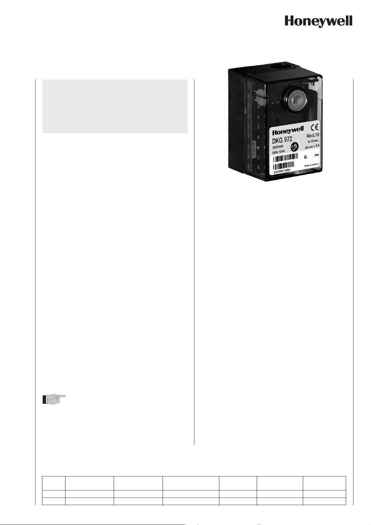
Gas Burner Safety Control DKG 972
For 2-stage atmospheric gas burners
Flame detection:
- Ionisation probe
- Infrared-flicker detector IRD 1020.1
- UV flame sensor UVD 971
INTRODUCTION
The burner control box DKG 972 controls and supervises
atmospheric burners for gas. They are approved and certified
according to the applicable European standards and
regulations.
The microprocessor-based programming sequence ensures extremely stable timings independent of voltage variations, ambient temperature and/or switch-on cycles. The
built-in information system not only provides a continuous
monitoring of the actual state of the box (very helpful especially for monitoring the start-up phase) but also informs
about the cause of a possible lock out. The lock out cause
is stored in such a way that it can be retrieved even after a
power failure.
The control box is designed for maximum safety in case of
fluctuations in the voltage supply. If the mains voltage drops
below the permitted level, operation is interrupted and the
control box automatically prevents the start sequence from
being repeated. In this way, the safety of the system is not
put at risk by a drop in the mains voltage. This low-voltage
protection works not only during start-up but also permanently during operation.
CONSTRUCTIONAL FEATURES
The control box circuitry is protected by a flame resistant,
transparent plug-in type plastic housing. A central fixing
screw locks the control box to the wiring base.
The plug-in control box incorporates the microprocessor
based timer, flame check and reset circuits.
Manual reset from lock out and set to lock out is provided by
a push button with an integrated LED information system.
A variety of cable entry points provides complete flexibility
for electrical wiring.
The wiring base S98 is equipped with spare- and extraterminals
and allows together with a variety of cable entry points utmost
flexibility of electrical wiring.
The DKG 972 are compatible with the TFI 812.
Different are only the pre- and post-ignition times.
Max. heating power according the limits in the Gas Appliance
Directive.
TECHNICAL DATA
Operating voltage 220 / 240 V (-15... +10%)
or 110 / 120 V (-15... +10%)
Fuse rating 10 A fast, 6 A slow
Power consumption ca. 12 VA
Max. load per output
- term. 3 ignition trafo 1.0 A, cos ϕ 0.2
- term. 5 + 6 solenoid valves 0.5 A, cos ϕ 0.4
- term. 7 alarm indicator 0.5 A, cos ϕ 0.4
- term. 4 auxiliary blower 2.0 A, cos ϕ 0.4
total load 4.0 A, cos ϕ 0.4
Reset time from lock out none
Re-cycling / repetition (max. 4x) after a loss-of-flame during
operation
Sensitivity 1 µA
min. ionisation current required 1.5 µA
Sensitivity for stray light 0.4 µA
Ionisation probe insulation probe - earth
Stray capacitance probe- earth
max. cable length < 3 m
Flame detectors
IRD 1020.1 side-on or end-on viewing
UVD 971 end-on viewing
Weight incl. Wiring base 190 g
Mounting position any
Protection class IP 40
Approved ambient parameter
for control and flame detector max. 95% at 30° C
- for operation -20° C... +60° C
- for storage -20° C... +80° C
Build-up of ice, penetration of
water and condensing water are inadmissible
Approvals according
to European standards EN 298 and EN 230, as
Classified acc. to EN 298 ATLLXN
50 Hz (±5%)
60 Hz (±5%)
max. 16 A during 0,5 sec
greater than 50 MΩ
less then 1000 pF
well as all other relevant
Directives and standards
Table of timings (sec.)
Model waiting time start pre-ignition time Stray light monitoring safety time post-ignition time delay 2nd-stage
05 12 3 5 5 4 25
10 12 3 5 10 9 25
EN1C-0127SZ20 R0305
tw tvz tf ts tn tv2
1
Page 2
APPLICATION FEATURES
1.2 Lock-out diagnoses
1. Information system
The information system is microprocessor based and reports on all aspects of burner control box operation and
flame supervision. It informs continuously about the actual
programming sequence the unit is just performing. Besides
monitoring of the programming sequence it also allows to
identify errors during start-up of operation without any
additional testing devices. The automatically performed
diagnosis is a valuable tool which facilitates service/
maintenance work and therefore saves costs. The analyses
of the error cause can be done directly on stage or if not
possible afterwards as the lock out reason is stored in a nonvolatile lock out mode memory.
The information system communicates with the outside
world using a LED (the used Flash-Code is similar to the
Morse-Code). The messages are optically transmitted by a
appropriately flashing LED. Using an additional terminal
(optional), the messages can be recorded and displayed in
easy readable form.
1.1 Programming sequence display
The built-in microprocessor controls not only the programming sequence but the information system too. The
individual phases of the programming sequence are
displayed as Flash-Code.
The following messages can be distinguished:
In case of a failure the LED is permanently illuminated. Every
10 seconds the illumination is interrupted by a flash code,
which indicates the cause of the error. Therefore the following
sequence is performed which is repeated as long as the unit
is not reset.
Sequence:
illuminated phase dark phase Flash-Code dark phase
❘ ❚ ❚ ❚ ❚
for 10 sec for 0.6 sec for 1.2 sec
Error diagnosis
Error message Flash-Code Possible fault
lockout ❘ ❚ ❚ ❚ ❚ within lock out safety time
no flame establishment
stray light ❘ ❘ ❚ ❚ ❚ stray light
during monitored phase,
detector may be faulty
Flash-Code for manual lock out
manual/external ❘ ❘ ❚ ❚ ❚ ❚ ❚ ❚ ❚ ❚
lock out
(see also 3. lock out and reset)
2. Flame detection
Message Flash-Code
waiting time ❘ ❘ ❘ .
tw
pre-ignition ❘ ❘ ❘ ❘ .
tvz
safety time ts ❚ ❘ .
post ignition tn
delay time to valve V2 ❚ ❘ ❘ .
tv2
running ❘ _
low mains voltage ❘ ❚ ❚ _
Internal fuse defect ❘ ❚ _
> control box defect
Description
❘ = short pulse
❚ = long pulse
. = short pause
_ = long pause
The following types of flame detectors are suitable:
– Ionisation probe, temperature resistant material, well
insulated (material and insulation same as for ignition
electrode).
– Infrared-flicker detector type IRD 1020.1 with mounting
flange M 93 or the UV solid state flame sensor UVD 971.
Flame detection using an ionisation probe is only possible
in conjunction with mains supplies which provides a neutral earth connection.
Connecting the IRD 1020.1 or UVD 971 the correct wiring
has to be observed.
2.1 Stray light monitoring
The stray light check is performed at the end of the prepurge time for thr duration as mentioned in the table of
timings.
DKG 972
2
Page 3

3. Lock out and reset
6. Mounting and electrical wiring
The unit can be reset or brought into lock out mode in two
different ways:
Internal
In the lock out case the unit can be reset by pushing the builtin button meaning a new start-up cycle is performed.
External
Instead of using the built-in lock out button the same
function can be achieved by using an external button which
connects terminal 9 with A (see also circuit and block
diagram).
If the pushputton (internal or external) is pressed during
normal operation or during the start sequence for more then
3 sec. and afterwards released, the control box will perform
a shutdown.
Please note
The unit can only be brought to lockout mode or
be reseted if power is applied to the unit.
4. Low-voltage protection
at 220 / 240V (110 / 120V) nominal voltage
The mains voltage has to be more than 187 V
order to allow the unit to perform a start-up.
(94 V
eff
eff
) in
The mains voltage is not only monitored in the start-up
phase but also permanently during operation. If the voltage
drops below < 160 V
the control box proceed to safety shut-down and goes into
(80 V
eff
) during start-up or run time
eff
a waiting status. If the voltage rises again, the control box
performs automatically a start-up as soon as the mains
voltage is > 187 V
(94 V
eff
) .
eff
Wiring base:
– 3 earth terminals with additional terminal for burner
earthing
– 3 neutral terminals with internal permanent connection to
neutral terminal 8
– 2 independant spare terminals (S1 and S2)
– extra terminals A, B and C are standard (wiring base S98
12-pin)
– 2 slide-in plates and 2 easy knock out holes plus 2 knock
out holes in the base bottom faciliate the base wiring
Please note
To assist trouble-free operation the main neutral
connection terminal 8 in the wiring base must be
fully tightened. The terminal screws are already in
the undone position. To connect a wire to the
terminal, the screw only needs to be fastened.
General: The control box and detector probes should not be
subjected to excessive vibration.
5. Safety
The design and control sequence of the DKG 972 controls
will comply with the currently applicable standards and
regulations (see also TECHNICAL DATA).
DKG 972
3
Page 4

INSTALLATION INSTRUCTIONS AND MAINTENANCE
3. Fault finding
1. Important notes
– The controls must be installed by qualified personnel
only. The relevant national regulations have to be
observed.
– On commissioning the wiring has to be carefully check-
ed according the appropriate diagram, Incorrect wiring
can damage the unit and endanger the installation.
– The fuse rating has to ensure that the limits specified in
TECHNICAL DATA will not be exceeded. If these precautions are not observed, the effect of a short circuit can
cause severe damage to the control and installation.
– For safety reasons a minimum of one control shutdown
every 24 hours has to be observed.
– Disconnect the mains before the control box is plugged
in or out.
– The control box is a safety device and must not be
opened!
2. Function control
For safety reasons the flame detection system should be
tested on commissioning the installation as well as after a
service or longer shut-down.
a) Attempt to start with gas valve closed:
– At the end of the safety interval
-> Lockout
b) After a normal start, with the burner in operation, close
the gas valve:
– After restart at the end of the safety interval
-> Lockout
The built-in information system facilitate the trouble shooting
in the case of problems occurring during start-up or during
operation.
A list of possible lock out messages can be found in
APPLICATION FEATURES chapter 1.2.
Please note:
The control box is locked in lock out mode
and the reasen for the lock out is displayed
until the control box is reset, either by an
internal or external reset (see also subject “3.
Lock out and reset").
Removing the control box from its wiring base or by
interrupting the supply line may not reset a lock out. Therefore,
by applying power, it needs 2-3 secs. before the control box
goes to lock out again and the cause of the last lock out.
Error Possible fault
Burner not working - Thermostat circuit open
- Faulty electrical wiring
- Mains voltage < 187 V (< 80 V)
- Terminal A continuously on
power (e.g. terminal A is used as
a support terminal)
After 2-3 secs. after applying - Control box has not been reseted
power. the unit goes to
lock out
Burner starts, - stray light signal during waiting
flame not established, time
lock out - no ignition or no fuel
Burner starts, - no or too low flame signal (min.
flame established, valves see TECHNICAL DATA)
after safety time, - wrongly wired, phase and neutral
lock out reversed
- Ionisation probe dirty, broken or
has contact to frame ground
- too little light on flame sensIor
(IRD)
DKG 972
4
Page 5

CIRCUIT AND TIMING DIAGRAM DKG 972
ST RT EV
Ph
max. 10 A fast
6 A slow
HS
GW
123456789 A
V1
IS
M
Z
V2
SA
N
tw tf tvz tn ts tv2
IRD- OR UVD CONNECTION
IRD 1020.1
UVD 971
blue
black
brown
term. 8
term. 1
term. 9
HS Mains switch
GW Gas proving switch
ST Limit thermostat
RT Control thermostat
EV External reset and lock out button
IS Ionisation probe
(IRD 1020.1, UVD 971see separate diagram)
Z Ignition
V1 Solenoid valve, 1st-stage
V2 Solenoid valve, 2nd-stage
SA External lock out signal
M Auxiliary blower
tw Waiting time
tf Stray light monitoring
tvz Pre-ignition time
tn Post-ignition
ts Safety time
tv2 2nd-stage delay
BLOCK DIAGRAM DKG 972
Fault display
Oscillator
EEPROM
µC
Watchdog
Reset
µC
Flame
amplifier
RZ
rz
RV1 RV2 RS
rv1
rv2
13456789A
Information
system
rs
Reset and
lock out
Mains
monitoring
Power
supply
monitoring
Power
supply
DKG 972
5
Page 6

DKG 972 AND SOCKET
4,5
HOLDER M 93 FOR IRD
35
3
62,5
86
24
Reset button
30
44
Earth
30
M4
16
30
57-60
UVD 971 IRD 1020.1
29
29
38,5
24
Slide-in plate
35
25
Underside cable
entry ø16 mm
50
60
4
17
HOLDER M 74 FOR UVD
UVD = 29
IRD = 44
35
ø 14
ø20
48
14
15.1
48
ø20.5
26
4.5
3
4,5
4
26
7
21,8
21,8
ø13,5
UVD = 89
IRD = 104
VARIATION IRD
right
axial
left
ORDERING INFORMATION
ITEM DESIGNATION ITEM NO.
Control box DKG 972 Mod. 5 0332005
Control box DKG 972 Mod. 10 0332010
Control box DKG 972 Mod. 10 110 / 120V 50Hz 0332310
Control box DKG 972 Mod. 10 110 / 120V 60Hz 0332410
Socket Wiring base S98 12-pin 75310
Insert plate PG-Plate 70502
optional Cable entry plate 70503
Flame detector IRD 1020.1 end-on 16532
Flame detector IRD 1020.1 left 16533
Flame detector IRD 1020.1 right 16531
optional UVD 971 16722
Support for IRD Holder M93 for IRD 1020 59093
Support for UVD Holder M74 for UVD 59074
Connection cable Plug type, 3 core cable, 0.6 m with tag wire ends 7236001
The above ordering information refers to the standard version.
Special versions are also included in our product range. Specifications subject to change without notice
Page 7

Combustion Controls EMEA - Local Honeywell Sales Offices
France Spain
Honeywell SA Honeywell S.A.
Parc Technologique de St. Aubin Josefa Valcárcel, 24
Bâtiment Mercury – BP87 28027 Madrid
91193 Gif-Sur-Yvette Cedex SPAIN
FRANCE
Phone: (33) 1 60 19 80 00 Phone: (34) 9 13136100
Fax: (33) 1 60 19 81 81 Fax: (34) 9 13 13 61 27
internet: www.honeywell.fr internet: www.honeywell.es
Eastern Europe United Kingdom
Honeywell s.r.o. Honeywell Control Systems Ltd
Mlynske Nivy 73 Honeywell House, Arlington Business Park
PO Box 75 Bracknell
82007 Bratislava 27 Berkshire, RG12 1EB
SLOVAKIA UNITED KINGDOM
Phone: (421) 2 58247 400 Switchboard +44 (0)1344 656000
Fax: (421) 2 58247 415 Information Centre Tel +44 (0)1344 656235
Information Centre Fax +44 (0 )1344 656240
e-mail: info.slovakia@honeywell.com Email: Uk.infocentre@honeywell.com
internet: www.honeywelluk.com
Germany, Austria, Switzerland Benelux
Honeywell GmbH Honeywell B.V.
Kaiserleistrasse 39 Laarderhoogtweg 18
63067 Offenbach 1101 EA Amsterdam Z.O.
DEUTSCHLAND THE NETHERLANDS
Phone: (49) 6 980640 Phone: (31) 2 05656911
Fax: (49) 69 81 86 20 Fax: (31) 2 05 65 66 00
internet: www.honeywell.de internet: www.honeywell.nl
Italy
Honeywell S.r.l.
Via P. Gobetti, 2/B
20063 Cernusco sul Naviglio (MI)
ITALY
Phone: 39 02 92146 1
Fax: 39 02 92146 888
internet: http://www.honeywell.com/sites/it/
 Loading...