

Page 1
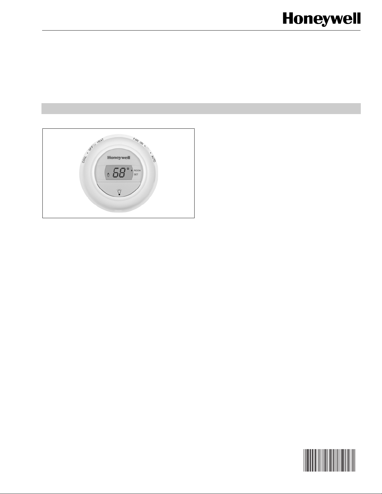
T8775A,C The Digital Round
Non-Programmable Thermostats
APPLICATION
The T8775A and T8775C Thermostats provide single-stage,
non-programmable temperature control for 24 Vac systems
with manual changeover from heat to cool.
The T8775A controls 2-wire heating-only systems.
The T8775C controls gas, oil or electric heating and cooling
systems.
™
PRODUCT DATA
FEATURES
• Attractive styling complements any decor.
• Simple to use. Turn the dial to adjust the setpoint
temperature.
• Large easy-to-read display. The temperature reading is
easily seen from a distance.
• Backlit display. On-demand backlighting makes it easy
to read the display in a dark room or hallway.
• No batteries required. The setpoi nt temperature is hel d
permanently in memory in the event of a power failure.
• Powered through heating-cooling system controls.
• System and Fan switches on the T8775C model.
• Manual changeover from heat to cool on T8775C
model.
• Easy installation and set up saves time and increases
installer productivity.
• Easily configurable by the use of DIP switches.
• Fahrenheit or Celsius temperature display for added
flexibility.
• Selectable heating cycle rates (1, 3, 6, 9 CPH) for a
variety of applications.
• Cooling cycle rate is fixed at 3 CPH. This is the
standard compressor setting.
• Minimum off-time for the compressor in the cooling
mode. Protects and extends the life of the equipment.
• Decorative cover plate is available to cover marks on
the wall or to mount the T8775 Thermostat to an
electrical box.
® U.S. Registered Trademark • Patents Pending
Copyright © 2004 Honeywell International Inc.
All Rights Reserved
Contents
Application.........................................................................1
Features............................................................................1
Specifications....................................................................2
Ordering Information .........................................................2
Installation.........................................................................3
Wiring................................................................................4
Customize Thermostat......................................................5
Set System and Fan Switches ..........................................6
Checkout...........................................................................7
Troubleshooting Guide......................................................8
68-0279
Page 2

T8775A,C THE DIGITAL ROUND™ NON-PROGRAMMABLE THERMOSTATS
3
SPECIFICATIONS
IMPORTANT
The specifications given in this publication do not
include normal manufacturing tolerances; therefore,
an individual unit might not exactly match the listed
specifications. Also, this product is tested and calibrated under closely controlled conditions, and some
minor differences in performance can be expected if
those conditions are changed.
Models: T8775A and T8775C TRADELINE® models include
a thermostat, wallplate for mounting and wiring, mounting
hardware, 4074FAB resistor, installation instructions and an
owner’s guide.
Electrical Ratings:
24 Vac nominal: 18 Vac to 30 Vac, 60Hz.
Heating: .02 to 1.5 A run; 3.5A inrush.
Cooling: .02 to 1.5 A run; 6.0 A inrush.
Fan: .02 to 0.5 A run; 2.5A inrush.
Temperature Ratings:
Setting Range:
40°F to 90°F (4.5°C to 32.0°C) in heating.
45°F to 99°F (7.0°C to 37.0°C) in cooling.
Ambient Range:
40°F to 110°F (4.4°C to 43.3°C).
Shipping Temperature Range:
-20°F to 120°F (-28.9°C to 48.9°C).
Humidity Ratings: 5% to 90% RH, non-condensing.
Mounting Hardware:
Sheet metal screws: Two 1-in. (25 mm) 4-24, type AB.
Drywall anchors: Two conical anchors, 3/16 in. (5 mm)
diameter by ¾ in. (19 mm) length.
4074 FAB Resistor:
1 Kohm, 3 Watts.
Installation Instructions packed with resistor.
Batteries: Not required.
Finish: Premier White®.
Accessories:
50000066-001 Decorative Cover Plate. Used to cover wall
marks, or to mount T8775 Thermostat to an electrical box.
32007680-001 Cover Ring.
Dimensions: See Fig. 1.
2-5/8 (67)
M19676
-11/16
(94)
ROOM
SET
1-7/16
(37)
Fig. 1. T8775 Thermostat dimensions in in. (mm).
ORDERING INFORMATION
When purchasing replacement and modernization products from your TRADELINE® wholesaler or distributor, refer to the
TRADELINE® Catalog or price sheets for complete ordering number.
If you have additional questions, need further information, or would like to comment on our products or services, please write or
phone:
1. Your local Honeywell Automation and Control Products Sales Office (check white pages of your phone directory).
2. Honeywell Customer Care
1885 Douglas Drive North
Minneapolis, Minnesota 55422-4386
In Canada—Honeywell Limited/Honeywell Limitée, 35 Dynamic Drive, Scarborough, Ontario M1V 4Z9.
International Sales and Service Offices in all principal cities of the world. Manufacturing in Australia, Canada, Finland, France,
Germany, Japan, Mexico, Netherlands, Spain, Taiwan, United Kingdom, U.S.A.
68-0279 2
Page 3
INSTALLATION
WALL PLATE
9
NO
T8775A,C THE DIGITAL ROUND™ NON-PROGRAMMABLE THERMOSTATS
YES
NO
ROOM
SET
5 FEET
[1.5 METERS]
NO
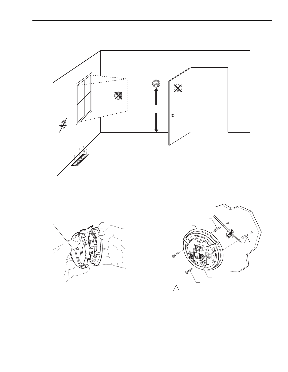
Fig. 2. Typical thermostat location.
Separate Wallplate from Thermostat
1. Place your thumbs on top of the thermostat and wallplate. Use your thumbs to pull the thermostat away from
the wallplate. See Fig. 3.
TOP OF
THERMOSTAT
M1967
Fig. 3. Separate wallplate from thermostat.
M19716A
Mount wallplate to wall (See Fig. 4) as follows:
WALL ANCHORS (2)
WALL PLATE
WIRING HOLE
1 INCH SCREW (2)
1 WHEN USING WALL ANCHORS, DRILL 3/16 IN. HOLES
FOR DRYWALL, 7/32 IN. HOLES FOR PLASTER.
1
M19499
Mount Wallplate to Wall
NOTE: Level wallplate for appearance only. The thermostat
functions normally even when not mounted level.
Fig. 4. Mount wallplate to wall.
1. Pull the thermostat wires through the wiring hole on the
wallplate.
2. Use a pencil to mark the center of the screw holes on
the left and right sides of the wallplate.
3. Remove the wallplate from the wall and drill two 3/16 in.
(5 mm) holes in the wall (if drywall) at the locations you
marked. For materials such as plaster, drill 7/32 in.
(6 mm) holes where marked.
3 68-0279
Page 4

T8775A,C THE DIGITAL ROUND™ NON-PROGRAMMABLE THERMOSTATS
0
G
A
M19496
N
S
3
4
S
5
S
4. Tap the provided wall anchors into the drilled holes until
they are flush with the wall.
5. Pull the thermostat wires through the wiring hole on the
wallplate and reposition the wallplate over the wall
anchors.
6. Attach the wallplate to the wall with the screws provided.
7. After wiring the wallplate, plug the hole to prevent drafts
from affecting the thermostat; see Wiring section.
WIRING
IMPORTANT
All wiring must comply with local electrical codes and
ordinances. Disconnect the power supply to prevent electrical
shock or equipment damage.
NOTE: To ensure proper mounting of thermostat, restrict all
Use 18-gauge wire to wire the T8775A,C
Thermostats.
wiring to the shaded area. See Fig. 5.
MOUNTING
HOLES
Refer to Fig. 7 through 11 for typical wiring diagrams.
R
1
1
POWER SUPPLY. PROVIDE DISCONNECT MEAN
AND OVERLOAD PROTECTION AS REQUIRED.
W
HEATING
RELAY OR
VALVE COIL
M1951
Fig. 7. Typical hookup of T8775A in a heat-only system.
O
B
Rc
2
R
G
Y
W
WIRING
HOLE
RESTRICT WIRIN
TO SHADED ARE
M1968
Fig. 5. Restrict T8775 wiring to shaded area.
The shape of the terminals permits insertion of straight or
wraparound wiring connections; either method is acceptable.
See Fig. 6.
FOR STRAIGHT INSERTIO
STRIP 5/16 IN. (8 MM).
FOR WRAPAROUND
INSERTION STRIP
7/16 IN. (11 MM).
Fig. 6. T8775 wiring connections.
1
1 POWER SUPPLY. PROVIDE DISCONNECT MEAN
AND OVERLOAD PROTECTION AS REQUIRED.
2 FACTORY INSTALLED JUMPER.
HEATING
RELAY OR
VALVE COIL
FAN
RELAY
M1951
Fig. 8. T ypical hookup of T8775C in heat-only system with
fan.
O
B
Rc
2
R
1
1 POWER SUPPLY. PROVIDE DISCONNECT MEAN
AND OVERLOAD PROTECTION AS REQUIRED.
2 FACTORY INSTALLED JUMPER.
G
Y
W
HEATING
RELAY OR
VALVE COIL
COMPRESSOR
CONTACTOR
FAN
RELAY
M1951
68-0279 4
Fig. 9. T ypical hookup of T8775C in heat-cool system with
single transformer.
Page 5

T8775A,C THE DIGITAL ROUND™ NON-PROGRAMMABLE THERMOSTATS
7
6
Y.
7
B
Rc
2
R
G
Y
W
COMPRESSOR
CONTACTOR
HEATING
1
1 POWER SUPPLY. PROVIDE DISCONNECT MEANS
AND OVERLOAD PROTECTION AS REQUIRED.
REMOVE FACTORY INSTALLED JUMPER BETWEEN R AND RC.
2
RELAY OR
VALVE COIL
FAN
RELAY
1
M1951
Fig. 10. Typical hookup of T8775C in heat-cool system
with two transformers.
4
O
B
Rc
2
R
1
G
Y
3
W
COMPRESSOR
CONTACTOR
FAN
RELAY
HEAT
CHANGEOVER
VALVE
CHANGEOVER
COOL
VALVE
FUEL SWITCH
M1949
Fig. 12. Fuel switch.
DIP Switch
To adjust the heat cycle rate or the Fahrenheit/Celsius
temperature display, locate DIP switch 1, 2 and 3 on the back
of the thermostat. See Fig. 13.
BACK OF THERMOSTAT
1 2 3
ON
1 POWER SUPPLY. PROVIDE DISCONNECT MEANS
AND OVERLOAD PROTECTION AS REQUIRED.
2 FACTORY INSTALLED JUMPER.
3 USE A JUMPER WIRE (NOT SUPPLIED) TO CONNECT W TO
4 USE EITHER O OR B FOR HEAT PUMP CHANGEOVER.
M1951
Fig. 11. Typical hookup of T8775C in single-stage heat
pump system.
CUSTOMIZE THERMOSTAT
Setting Fuel Switch (T8775C only)
The fuel switch is preset at the factory in the F position. See
Fig. 12. This is the correct setting for gas or oil systems. If the
T8775C is being installed on an electric heat system, or a heat
pump, set the switch to the E position. The E position allows
the fan to turn on immediately with the heating equipment in a
system where the G terminal is connected.
DIP SWITCH
M19567
Fig. 13. DIP switch.
Set Heat Cycle Rate
Use DIP switches 1 and 2 to set the heat cycle rate. See
Table 1.
Table 1. Heat Cycle Rate.
Cycles
Per
Heating System
Hour
Steam, Gravity 1 On On
High Efficiency Warm Air (90%+
3OffOn
efficiency), Hot Water, Heat Pump
Gas or Oil Warm Air (factory setting) 6 Off Off
Electric Warm Air 9 On Off
In Floor Radiant Heat Check with manufacturer
for recommended cycle
rate.
5 68-0279
DIP
Switch
1
DIP
Switch
2
Page 6

T8775A,C THE DIGITAL ROUND™ NON-PROGRAMMABLE THERMOSTATS
1
E
.
9
Fahrenheit/Celsius Indication
Use DIP switch 3 to set the desired temperature indication. See
Table 2.
(T8775C ONLY)
Table 2. Temperature Indication.
Fahrenheit/Celsius Display DIP Switch 3
Fahrenheit (factory setting) Off
Celsius On
SELECTS
COOL/OFF/HEAT
ROOM
SET
(T8775C ONLY)
SELECTS
ON/AUTO
SHOWS THAT THE
CURRENT ROOM
TEMPERATURE IS
DISPLAYED.
Mount Thermostat to Wallplate (see Fig. 14)
ENGAGE TABS
AT BOTTOM OF
THERMOSTAT
AND WALL PLATE.
PRESS UPPER
EDGE OF CASE
TO LATCH
M19498
Fig. 14. Mount thermostat to wallplate.
SET SYSTEM AND FAN SWITCHES
(T8775C ONLY)
SYSTEM Switch: (See Fig.15)
Heat: The thermostat controls the heating system.
Off: Both the heating and cooling systems are off.
Cool: The thermostat controls the cooling system.
SHOWS THAT THE
CURRENT TEMPERATUR
DISPLAYS ROOM
OR SET TEMPERATURE
DISPLAYS AND ADJUSTS
TEMPERATURE SETPOINT/TURNS
BACKLIGHT ON
SETPOINT IS DISPLAYED
Fig. 15. T8775 Thermostat (features and operation).
W
A
R
E
L
O
O
C
R
ROOM
SET
M
E
R
M19582
Fig. 16. T8775 Thermostat.
M1968
FAN Switch: (See Fig.15)
Auto: The fan only runs with the heating and cooling
system.
On: The fan runs continuously. Use for improved air
circulation.
FEATURES AND OPERATION
Features and operation of The Digital RoundTM Thermostat (see
Fig. 15 and 16):
• Simple to use. Turn the dial to adjust the temperature
setting.
• Large easy-to-read display. The temperature reading is
easily seen from a distance.
• Backlit display. On-demand backlighting makes it easy to
read the display in a dark room or hallway.
• No batteries required. The temperature setting is held
permanently in memory in the event of a power failure.
68-0279 6
Backlit Display
Push the backlight button to turn on the backlight (See Fig.
15).
Display Temperature Setpoint
1. Turn the dial one click to display the temperature setpoint. An indicator points to Set when the temperature setpoint is displayed (see Fig.17).
ROOM
SET
M1948
Fig. 17. Temperature setpoint display.
2. If a change to the temperature setpoint is not made
within five seconds, the display will switch to the current
room temperature. An indicator points to Room
when the room temperature is displayed (see Fig. 18).
Page 7

T8775A,C THE DIGITAL ROUND™ NON-PROGRAMMABLE THERMOSTATS
0
Table 3. T8775 Power Stealing.
ROOM
SET
M1949
Fig. 18. Room temperature display.
Adjust Temperature Setpoint
Turn the dial clockwise to raise the temperature setpoint. Turn
the dial counterclockwise to lower the temperature setpoint
(see Fig. 16).
System Switch T8775A T8775C
Heat R and W R and W
Off — R and W
Cool — Rc an d Y
The T8775 Thermostat only operates when mounted on the
wallplate with 24 Vac applied. Batteries are not required for
operation because the temperature setpoint is permanently
retained in memory.
Power Stealing Circuit
Sequence of Operations
Power Stealing
The T8775 thermostat steals power from R and W or Rc and
Y depending on the system switch position. See Table 3.
Table 4. Sequence of Operations.
Fan Switch Settings System Switch Settings Call for Action Energize Terminals Display Icons
Auto Off None None None
Auto Heat Heating
Auto Cool Cooling Y,G
On Off Fan G None
On Heat Heating W,G
On Cool Cooling Y,G
a
If fuel switch is set to E, both W and G are energized in a call for heat.
See Table 4 for Sequence of Operations.
a
W
Flame
Snowflake
Flame
Snowflake
CHECKOUT
Cooling (T8775C only)
CAUTION
Low Temperature Hazard.
Operating at too low of an outdoor temperature
may cause compressor damage.
Do not operate cooling if outdoor temperature is below
50°F (10°C). Refer to manufacturer’s
recommendations.
Minimum Off-Timer
The minimum off-timer in the T8775C Thermostat assures
that the cooling compressor does not turn on for at least five
minutes after it turns off. The snowflake will flash in the display
if there is a call for cooling during the 5-minute off-time.
The following activates the 5-minute minimum-off timer:
• Initial startup
• Power interruption
• Compressor turns off:
— Setpoint is raised above the room temperature
— System switch is changed from the cool mode
— Thermostat ends the call for cooling
1. Slide the system switch to COOL and the fan switch to
AUTO.
2. Lower the temperature setpoint several degree s below
the room temperature.
3. A snowflake will appear in the display and the cool-
ing should turn on.
4. Raise the temperature setpoint several degrees above
the room temperature.
5. The snowflake
the cooling should turn off.
will disappear from the display and
Heating
1. Slide the system switch to HEAT and the fan switch to
AUTO (T8775C only).
2. Raise the temperature setpoint several degrees above
the room temperature.
3. A flame will appear in the display and the heat should
turn on.
4. Lower the temperature setpoint below the room temperature.
5. The flame will disappear from the display and the
heat should turn off.
Fan
1. Slide the system switch to OFF and the fan switch to
ON. The fan should run continuously.
2. Slide the fan switch to AUTO. The fan should turn off.
NOTE: The 5-minute minimum-off timer does not apply to
heating.
NOTE: Make sure that all equipment responds properly to
the thermostat.
7 68-0279
Page 8

T8775A,C THE DIGITAL ROUND™ NON-PROGRAMMABLE THERMOSTATS
4
TROUBLESHOOTING GUIDE
HEATING OR COOLING EQUIPMENT
WILL NOT OPERATE.
PARTIAL DISPLAY
NO DISPLAY
NO AC POWER TO THERMOSTAT.
THERMOSTAT INOPERATIVE.
PRESENT SETTING TOO LOW/HIGH.
SYSTEM SWITCH ON THERMOSTAT
IN WRONG POSITION.
MINIMUM-OFF TIME IN COOLING.
INCORRECT WIRING.
HEATING OR COOLING EQUIPMENT
INOPERATIVE.
INOPERATIVE THERMOSTAT.
NO POWER TO THERMOSTAT.
• CHECK POWER TO HEATING AND COOLING EQUIPMENT
– ON-OFF SWITCH
– FUSE OR CIRCUIT BREAKER
– LOOSE 24V CONNECTION:
– AT THERMOSTAT
– AT FURNACE/AIR CONDITIONER
– INCORRECT WIRING (SEE WIRING DIAGRAMS)
SEE CHECKOUT SECTION.
ADJUST TEMPERATURE BY TURNING DIAL CLOCKWISE OR
COUNTER-CLOCKWISE.
RESET THERMOSTAT SYSTEM SWITCH.
WAIT UP TO FIVE MINUTES FOR THE COOLING EQUIPMENT
TO TURN ON.
CHECK WIRING DIAGRAMS.
CONSULT EQUIPMENT MANUFACTURER INSTRUCTIONS.
REPLACE THERMOSTAT.
• CHECK POWER TO HEATING AND COOLING EQUIPMENT
– ON-OFF SWITCH
– FUSE OR CIRCUIT BREAKER
– LOOSE 24V CONNECTION:
– AT THERMOSTAT
– AT FURNACE/AIR CONDITIONER
– INCORRECT WIRING (SEE WIRING DIAGRAM)
TEMPERATURE DISPLAY IS
INCORRECT.
TEMPERATURE SETTINGS WILL NOT
CHANGE. (EX: CANNOT SET THE
HEATING HIGHER OR THE
COOLING LOWER).
FAN DOES NOT OPERATE PROPERLY
IN HEAT OR COOL MODES.
THERMOSTAT MOUNTED
INCORRECTLY ON WALLPLATE.
THERMOSTAT IS CONFIGURED FOR
F OR C DISPLAY.
THE UPPER OR LOWER
TEMPERATURE LIMITS WERE
REACHED.
INCORRECT WIRING.
CHECK FUEL SWITCH POSITION.
HEATING OR COOLING EQUIPMENT
INOPERATIVE.
SEE MOUNT THERMOSTAT TO WALLPLATE SECTION.
RECONFIGURE THE DISPLAY. SEE CUSTOMIZE
THERMOSTAT SECTION.
CHECK THE TEMPERATURE SETPOINTS; TEMPERATURE
SETTING RANGE IS 40 F TO 90 F (4.5 C TO 32 C) IN HEATING
AND 45 F TO 99 F (7 C TO 37 C) IN COOLING.
CHECK WIRING DIAGRAMS.
SEE CUSTOMIZE THERMOSTAT SECTION.
CONSULT EQUIPMENT MANUFACTURER INSTRUCTIONS.
M1968
Automation and Control Solutions
Honeywell International Inc. Honeywell Limited-Honeywell Limitée
1985 Douglas Drive North 35 Dynamic Drive
Golden Valley, MN 55422 Scarborough, Ontario
68-0279 J.S. 4-04 www.honeywell.com/yourhome
M1V 4Z9
Printed in U.S.A. on recycled
paper containing at least 10%
post-consumer paper fibers.
 Loading...