

Page 1
Copyright © 2005 Honeywell Inc. EN2H-0220 GE51 R1005
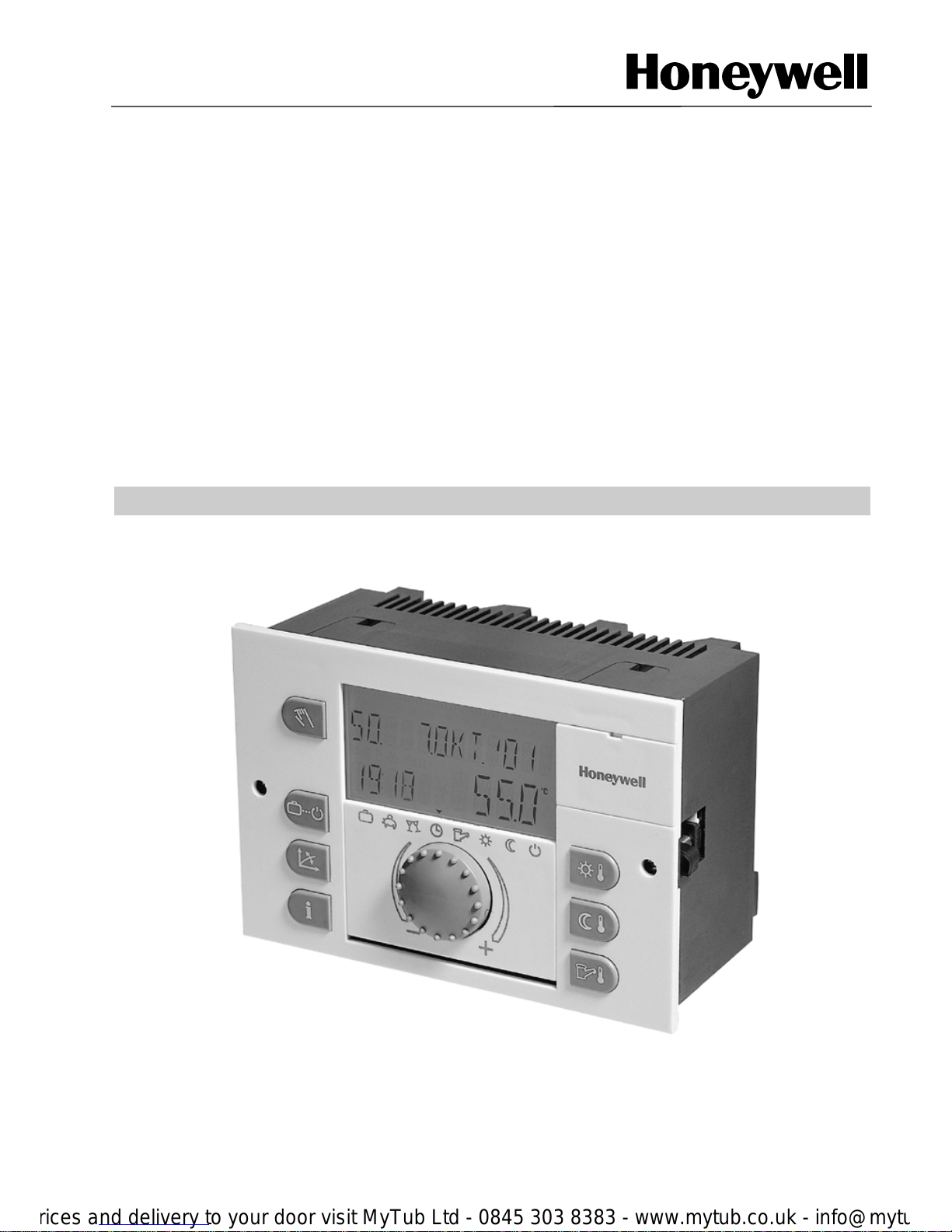
Heating Controller SDC
District Heating Controller DHC 43
OPERATING INSTRUCTIONS
Page 2

Page 3

Contents SDC / DHC 43
1 EN2H-0220 GE51 R1005
CONTENTS
1
SOFTWARE VERSION 3
2 SAFETY INSTRUCTIONS 4
2.1 Application 4
2.2 Conditions for start-up 4
2.3 Do not separate the controller from the mains 5
2.4 Electric installation 5
2.5 Cable dimensions 5
2.6 Maximum cable length 5
2.7 Cable installation 5
2.8 Cabinet earth and ground 6
2.9 Domestic hot water higher than 60 °C 6
2.10 Connecting accessories 6
2.11 Service and cleaning 7
3 DHC 43 / SDC – OVERVIEW 8
4 OPERATION 9
4.1 Interface 9
4.1.1 Basic display 10
4.1.2 Operating elements 10
4.1.2.1 Rotary Pushbutton (Press/Turn) 10
4.1.2.2 "Daytime Room Temperature" Key 11
4.1.2.3 "Night-time Room Temperature" Key 11
4.1.2.4 "Daytime DHW Temperature" Key 12
4.1.2.5 "Operating Mode" Key (Basic display) 13
4.1.2.6 "Heating Characteristic" Key 19
4.1.2.7 "System Information" Key 20
4.1.2.8 "Manual Mode" / "Emission Measurement" Key 22
4.2 Menu Selection 24
4.2.1 Time-Date Menu 25
4.2.2 Time programs Menu 26
4.2.3 System Parameter Menu 34
4.2.3.1 Language Selection 34
4.2.3.2 Time Programs 34
4.2.3.3 Control Mode 35
4.2.3.4 Summer Switch-off (heating limit) 37
4.2.3.5 Parameter Reset 38
4.2.4 Domestic Hot Water Menu 39
Page 4

SDC / DHC 43 Contents
EN2H-0220 GE51 R1005 2
4.2.4.1 DHW Economy Temperature 39
4.2.4.2 Legionella Protection-Day 39
4.2.5 Unmixed Circuit / Mixing Circuit 1 / Mixing Circuit 2 Menu 40
4.2.5.1 Reduced Mode 40
4.2.5.2 Heating System 41
4.3 Malfunction Messages 42
Page 5

Software Version SDC / DHC 43
3 EN2H-0220 GE51 R1005
1 Software Version
Please use this documentation in conjunction with
software versions V 1.0 and 2.1 of your controller. The
version will be displayed for about 8 s when the controller
is connected to the mains. If you may be using an older
version, please contact your heating specialist.
Page 6

SDC / DHC 43 Safety Instructions
EN2H-0220 GE51 R1005 4
2 Safety Instructions
2.1 Application
The Smile controller family DHC/SDC is designed
exclusively for the control of warm water heating and
district heating systems including domestic hot water
control. These systems should not exceed a flow
temperature of 120 °C.
2.2 Conditions for start-up
CAUTION The heating installation must be completed and filled with
water in order to prevent the pumps from running dry and
to avoid damage for the boiler.
The control system must be installed according to the
mounting instructions.
All electrical connections (power supply, burner, valve
actuator, pumps and sensors) must be carried out
according to the local rules and standards and must
comply with the attached wiring diagrams.
If a floor heating system is connected, a limiting
thermostat must switch off the pump if the flow
temperatures are too high.
The heating specialist must check the complete
installation before switching on the controller.
IMPORTANT NOTE! The actual time and date are already adjusted from the
factory and backed up by a battery.
There is a basic time program already activated and the
control functions for standard heating systems with low
temperature boilers are pre-adjusted.
Page 7

Safety Instructions SDC / DHC 43
EN2H-0220 GE51 R1005
5
2.3 Do not separate the controller from the mains
If this happens, the back-up battery will be unnecessarily
stressed. In addition, the frost protection functions of the
controller will be out of order.
2.4 Electric installation
Qualified personnel must carry out all electrical
connections.
2.5 Cable dimensions
1.5 mm² for all 230 V cable (power supply, burner,
pumps, actuators).
0.5 mm² for sensors, selectors, bus and analogue in- and
outputs.
2.6 Maximum cable length
Sensors selectors and analogue inputs
A maximum cable length of 200 meters is recommended.
Longer distances are possible but increase the risk of
interferences.
Relay outputs
Unlimited cable length.
Bus connections
A maximum cable length of 100 meters is strongly
recommended.
2.7 Cable installation
Cables for 230 V must be installed separate from low
voltage (sensor selector bus) cables.
Page 8

SDC / DHC 43 Safety Instructions
EN2H-0220 GE51 R1005 6
2.8 Cabinet earth and ground
Please install and connect the controllers according to
local rules and standards!
2.9 Domestic hot water higher than 60 °C
WARNING Please note that in the following cases there is a danger
at hot water tabs (kitchen, bath). In order to avoid
scalding please mix enough cold water.
Anti legionella automatic
If the anti legionella automatic is activated, the domestic
hot water will automatically be heated up to temperatures
around 65 °C order to kill legionella bacteria in the hot
water system.
Manual operation / Emission measurement
In the manual mode / emission measurement mode the
domestic hot water can be heated up to the maximum
possible boiler temperature because the burner and all
pumps are switched on and the valves will be completely
opened. In addition, here there is the danger of scalding
at all warm water tabs in the building. Please mix enough
cold water or switch the domestic hot water loading
pump manually off (if there is a switch at the pump).
Heating and domestic hot water are not temperature
controlled in these modes. These modes are especially
used by the emission measurement specialist or by the
installer in case the controller is defect. The high water
temperatures can however be avoided if the boiler
thermostat is adjusted to a max. of 60 °C.
2.10 Connecting accessories
CAUTION According to VDE 0730 the power supply for the
controller must have a separate main switch for life and
neutral. Please follow local rules and standards for
cabinet earth and ground!
As soon as there is power supply at the terminals 21, 22,
2, 6, 12 and 18, also the terminal rows X3 and X4 will
carry 230 V connections!
Page 9

Safety Instructions SDC / DHC 43
EN2H-0220 GE51 R1005
7
External switches must be installed if a manual switch
function is desired for pumps. All accessories (sensors,
selectors, etc.) must be connected according to the
attached wiring.
2.11 Service and cleaning
The controller is service free. The unit can be cleaned
with a moist cloth from the outside.
Page 10
SDC / DHC 43 Overview
EN2H-0220 GE51 R1005 8
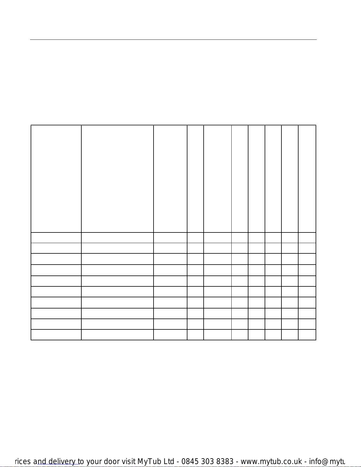
3 DHC 43 / SDC – Overview
This document describes the Smile controller family
DHC/SDC for panel installation and wall mounting. The
product is available in the following variations for use as
a built-in controller and as a wall-mounted controller:
Type
Number of output relays
2
nd
burner stage or
district heating valve closed
1
st
burner stage
Direct circuit
variable output 3
Mixing circuit 1
Mixing circuit 2
DHW loading pump
Variable output 2
Variable output 2
SDC 3-10
3-Rel. x x x
SDC 3-40
3-Rel. x
SDC 6-20
6-Rel. x x x x
SDC 7-21
7-Rel. x x x x x
SDC 8-21
6-Rel. + 2 Variable x x x x x x
SDC 9-21
7-Rel. + 2 Variable x x x x x x x
SDC 12-31
10-Rel. + 2 Variable x x x x x x x x
DHC 43-0*
3-Rel x
DHC 43-1*
7-Rel x x x x x
DHC 43-2*
7-Rel. + 2 Variable x x x x x x x
* District heating versions.
Page 11
Operation SDC / DHC 43
9 EN2H-0220 GE51 R1005
4 Operation
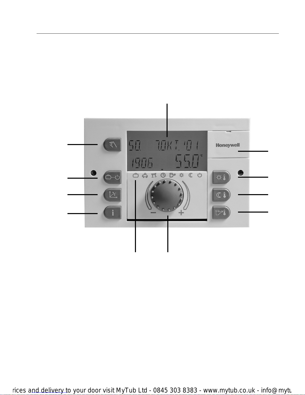
4.1 Interface
1 "Manual mode" key / "Emission Measurement" key (not applicable for district
heating controllers)
2 "Operating mode" key for permanent and temporary operating modes (Basic
display)
3 "Heating characteristics" key
4 "Information" key for the display of temperatures and operating statuses
5 Multi-functional Display
6 Cover clip for the service jack
7 "Daytime room temperature setpoint" key
1
5
6
10
11
2
3
4
7
8
9
Page 12
SDC / DHC 43 Operation
EN2H-0220 GE51 R1005 10
8 "Night-time room temperature setpoint" key
9 "DHW daytime temperature setpoint" key
10 Rotary pushbutton (push and turn)
11 Operating modes symbols
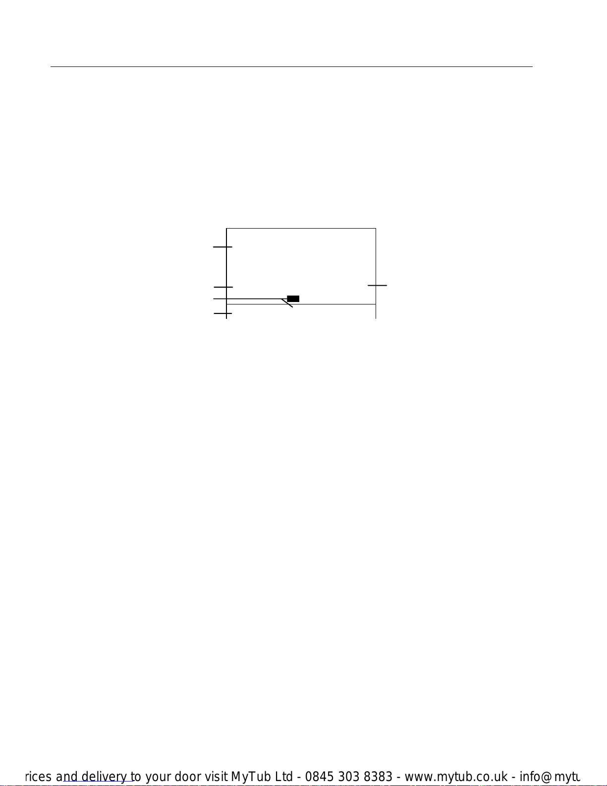
4.1.1 Basic display
The display illumination is activated with every push of a
key, respectively the rotary pushbutton and switches off
after a longer period of inactivity.
When the controller is first started or after a power cut a
segment test + fault diagnosis is carried out. After this
test the software version and the controller type is
displayed.
In the automatic mode, the basic display shows the
weekday, the date, the time and the heat generator
temperature. Depending on the adjusted operating mode
other information will be displayed.
Active heating limits will be shown with the "umbrella"
icon, frost protection with the "crystal" icon.
4.1.2 Operating elements
4.1.2.1 Rotary Pushbutton (Press/Turn)
By pressing the rotary pushbutton once, you can:
• Confirm inputs/values
By prolonged pressing (ca. 3 s) the rotary pushbutton,
you can:
MO. 18.MAR. 01
11.47 40.0
oc
æ ç è é ê ë ì í
Active operating mode
Date
Operating modes symbols
Heat generator temperature
Page 13

Operation SDC / DHC 43
11 EN2H-0220 GE51 R1005
• Shift to the menu selection level
• Get one menu level higher
By turning the rotary pushbutton, you can:
• Change values (clockwise increases values, counterclockwise decreases values)
• Browse through menus
4.1.2.2 "Daytime Room Temperature" Key
This key sets the room temperature setpoint in the
automatic program during the heating cycles as well as
during the PARTY and HEATING operating modes. In
control mode 1, the setpoint is identical for all the heating
circuits. In control mode 2, the setpoint can be individual
for all circuits. To change the control mode, see "Mode"
section
Setting:
► Press the "daytime room temperature" key ¥.
► Set the flashing room temperature default value by
turning the rotary pushbutton î to the desired value.
► Confirm the set value by pressing either the "daytime
room temperature" key ¥ key or the rotary
pushbutton î.
► Alternatively, the value can be acquired by automatic
exit after the set INFO-TIME (see "System
Information).
Factory setting 20 °C
Setting range 5...30 °C
4.1.2.3 "Night-time Room Temperature" Key
This key sets the reduced room temperature setpoint in
the automatic program between the heating cycles as
well as during the ABSENT and REDUCED operating
modes. In this operating mode, the setpoint is identical
for all the heating circuits.
¥
¦
ROOM-DAY
22.0
oc
æ ç è é ê ë ì í
Page 14

SDC / DHC 43 Operation
EN2H-0220 GE51 R1005 12
Setting:
► Press the "night-time room temperature" key ¦.
► Set the flashing room temperature default value by
turning the rotary pushbutton î to the desired value.
► Confirm the set value by pressing either the "night-
time room temperature" key ¦ or the rotary
pushbutton î.
► Alternatively, the value can be acquired by automatic
exit after the set INFO-TIME (see "System
Information).
Factory setting 16 °C.
Setting range 5...30 °C
4.1.2.4 "Daytime DHW Temperature" Key
This key sets the DHW temperature setpoint during the
DHW operating times in the automatic program as well
during the PARTY and HEATING operating modes.
This setting value applies also for domestic hot water
only mode (manual summer mode).
Setting:
► Press the "daytime DHW temperature" key §.
► Set the flashing room temperature default value by
turning the rotary pushbutton î to the desired value.
► Confirm the set value by pressing either the" daytime
DHW temperature" key § or the rotary pushbutton î.
► Alternatively, the value can be acquired by automatic
exit after the set INFO-TIME (see "System
Information).
Factory setting 50 °C
Setting range Hot water economy temperature...water heater maximum
temperature limit (service setting)
§
ROOM-NIGHT
16.0
oc
æ ç è é ê ë ì í
DHW
DAY 22.0
oc
æ ç è é ê ë ì í
Page 15
Operation SDC / DHC 43
13 EN2H-0220 GE51 R1005
Single DHW loading
Function
Pushing the" daytime DHW temperature" key § longer
than 3 s will lead to the single DHW loading function.
This function will override the actual time program.
The operator will see an adjustable time with the
following meaning:
0 s: the single loading function will be carried
out only once. The setpoint is the DHW
day setpoint. As soon as the setpoint is
reached, this function is disabled again.
>0 s: The DHW day setpoint is maintained for
the adjusted time interval. The time
interval can be adjusted between 0 and
240 min with the rotary pushbutton.
4.1.2.5 "Operating Mode" Key (Basic display)
The desired operating mode can be selected with this
key. The operating mode appears in plain text, while at
the same time a cursor at the bottom of the display
indicates the relevant operating mode symbol. The
selected operating mode applies for all heating circuits in
control mode 1. In control mode 2, every heating circuit
can be assigned with its own operating mode. To change
the control mode, see 4.2.3 System Parameter Menu.
¢
I TIME DHW
2.0
min
æ ç è é ê ë ì í
Page 16

SDC / DHC 43 Operation
EN2H-0220 GE51 R1005 14
Overview of the Operating Modes
Arrow on the Symbol Program Display in basic mode Setting
æ
Holiday
Return Date
ç
Absence
P1 (2, 3), Return
time
è
Party
P1 (2,3),
Party End Time
é
Automatic
P1 (2, 3)
ê
Summer
P1 (2, 3)
ë
Constant Heating
Mode
ì
Constant Reduced
Mode
í
Constant
Standby Mode
Page 17

Operation SDC / DHC 43
15 EN2H-0220 GE51 R1005
Setting:
► Press the "operating mode" key ¢.
► Set the flashing operating mode by turning to the
desired operating mode.
► Confirm the value by pressing the "operating mode"
key ¢ or the rotary pushbutton î.
► In case of short-term operating modes (Holiday,
Absence, Party) set the desired target value by
turning the rotary pushbutton î and confirm the set
value as described above.
► Alternatively, the value can be acquired by automatic
exit after the set INFO-TIME (see "System
Information).
► Return to the basic display by keeping the "operating
mode" key ¢ pressed for about 3 s.
4.1.2.5.1 Holiday Mode (Short-term Program)
By means of this program, the heating and domestic hot
water (DHW) can be switched off with frost protection for
the whole duration of the holiday.
Application Long absence during the heating season
Factory setting Current date
Setting range Current date...Current date + 250 days
Display An active holiday program appears on the basic display
with the indication of the return date.
HOLIDAY TIL
18.20
24.09
æ ç è é ê ë ì í
Page 18

SDC / DHC 43 Operation
EN2H-0220 GE51 R1005 16
4.1.2.5.2 Absence Mode (Short-term Program)
By means of this program, the heating can be
temporarily switched off in case of a brief period of
absence. During the period of absence all the heating
circuits are controlled according to the specified reduced
room temperature. At the expiry of the set time, the
heating circuits return automatically to the operating
mode that was active before the absence program.
Short-term programs like Party or Holiday will be skipped
during this mode.
Application Short-term absence within the heating season
Factory setting P1 from the time of activation (the next switch on
time leads back to automatic mode)
Setting range P1 (absent up to the next switch-on time)
0.5 hours from the activation...24 hours from the
activation
Display An active absence program appears on the basic display
with the indication of the return time.
4.1.2.5.3 Party Mode (Short-term program)
This program provides for a one-time intermediate
heating of all the heating circuits up to a specified time
and skips completely or in part a forthcoming or an
already active reduced cycle. At the expiry of the set
time, the heating circuits return automatically to the
operating mode that was active before the party
program.
Short-term programs like Absence or Holiday will be
skipped during this mode.
Application One-time unscheduled extension of the heating or
intermediate heating during reduced mode
Factory setting P1 after activation (the next switch on time leads back to
automatic mode)
ABSENT TIL
20.10
01.10
æ ç è é ê ë ì í
PARTY TIL
20.10 02.30
æ ç è é ê ë ì í
Page 19

Operation SDC / DHC 43
17 EN2H-0220 GE51 R1005
Setting range P1 (Party mode up to the next switch-on time), or
0.5 hours from the activation...24 hours from the
activation
Display An active party program appears on the basic display
with the indication of the duration of the party.
4.1.2.5.4 Automatic Mode
In automatic mode automatic time programs with various
heating times are available. The standard time programs
set at the factory can be overwritten if necessary with
one’s own switching times (see the Time programs
Menu).
If necessary, up to three different switching programs
can be utilized (see Time Programs)
Display An active automatic program appears on the basic
display with the current date and time.
4.1.2.5.5 Manual Summer Mode (Only DHW)
In this program only the domestic hot water circuit
remains active and the temperature is controlled
according to the DHW setpoint and the DHW time
program. The heating system is frost protected.
Display A manual summer mode appears on the basic display
with the indication SUMMER.
FR. 21.SEP.01
13.15 58.0
oc
æ ç è é ê ë ì í
SUMMER
58.0
oc
æ ç è é ê ë ì í
Page 20

SDC / DHC 43 Operation
EN2H-0220 GE51 R1005 18
4.1.2.5.6 Constant Heating Mode
This program provides for uninterrupted heating
according to the specified daytime room temperature.
The DHW heating works continuously according to the
specified DHW setpoint.
Display An active constant heating mode appears on the basic
display with the indication HEATING.
4.1.2.5.7 Constant Reduced Mode
This program provides for a constant reduced heating
mode according to the specified reduced room
temperature corresponding to the ECO (frost protected
switch-off mode) or ABS (reduced mode) reduced
operating mode set at a heating circuit level in
compliance with the low limit of the relevant heating
circuit.
See the parameter menu Unmixed Circuit, Mixing circuit
1 or Mixing circuit 2/Parameter 1 = Reduced Mode. The
DHW heating works constantly according to the specified
DHW economy temperature (see the menu DHW
/Parameter 1- DHW Economy Temperature).
Display An active constant reduced mode appears on the basic
display with the indication REDUCED.
4.1.2.5.8 Standby Mode
In this mode the entire system is switched off and
provided with frost protection (all frost protection
functions are active). The DHW heating is blocked and
has frost protection. At tank temperatures of below 5 °C
the water is reheated to 8 °C.
HEATING
12.00
22.0
oc
æ ç è é ê ë ì í
RED. HEATING
19.40
40.0
oc
æ ç è é ê ë ì í
STANDBY
17.20
55.0
oc
æ ç è é ê ë ì í
Page 21

Operation SDC / DHC 43
19 EN2H-0220 GE51 R1005
Display An active standby mode appears on the basic display
with the indication STANDBY.
4.1.2.6 "Heating Characteristic" Key
This key makes it possible to set the heating
characteristics for the system’s heating circuits.
The slope of the heating characteristic describes the
relation between the change in the flow temperature with
the change in the outside temperature. In case of large
heating surfaces like floor heating systems the heating
characteristic is less steep compared to smaller heating
surfaces (e.g. radiators).
The set value refers to the lowest outside temperature at
the basis of the heat demand calculation.
IMPORTANT NOTE! This parameter is to be set by the heating technician and
should not be altered anymore.
Setting:
► Press "heating characteristic" key £.
► Turn the rotary pushbutton î in order to select the
desired heat circuit.
► Confirm the set value by pushing the rotary
pushbutton î.
► Turn the rotary pushbutton î in order to set the
characteristic type.
► Confirm the set value by pushing the rotary
pushbutton î.
► Adjust the flashing value and confirm.
► To return to the basic display, press the "heating
characteristic" key £.
► Alternatively the value can be acquired by automatic
exit after the set INFO-TIME (see "System
Information).
Setting Range 0.20...3.5
Factory Setting Direct heating circuit (DK): = 1.50
Mixer heating circuit 1 (MK1): = 1.00
Mixer heating circuit 2 (MK2): = 1.00
HEATCURVE
MC1 1.20
æ ç è é ê ë ì í
£
Page 22

SDC / DHC 43 Operation
EN2H-0220 GE51 R1005 20
4.1.2.7 "System Information" Key
With the "information" key ¤ a query of all the system
information can be made by using the rotary pushbutton.
The first data item to appear always is the outside
temperature. By turning the rotary pushbutton î
clockwise the system temperatures and the counter and
consumption statuses appear; by turning the rotary
pushbutton î counter-clockwise the operating statuses
of the connected system components appear.
NOTE The information displayed depends on the plant
components installed and the control loops.
¤
Page 23

Operation SDC / DHC 43
21 EN2H-0220 GE51 R1005
Example System Information
Heating circuit information
retrievable by turning the
rotary pushbutton to the left
Press ¤ key
System temperatures,
counter data retrievable by
turning the rotary pushbutton
to the right
Outside Temperature
Mean Value / Actual Value
Program/Operating mode
Direct circuit/Pump status
Outside temperature
Mini–Maxi (0:00–24:00)
Program/Operating mode
Mixing circuit 1/Pump status
Heat generator temperature
Setpoint / Actual value
Servomotor
Mixing circuit 1/Status
DHW temperature
Setpoint / Actual value
Program/Operating mode
Mixing circuit 2/Pump status
Flow temp. direct circuit
Setpoint / Actual value
Servomotor
Mixing circuit 2/Status
Flow temp. mixing circuit 1/2
Setpoint / Actual value
Room temp. direct circuit
Setpoint / Actual value
Room temp. mixing circuit ½
Setpoint / Actual value
Program/Operating mode
DHW circuit/Pump status
Variable Input 1
Setpoint / Actual value
Heat generator
Status
Variable Input 2
Setpoint / Actual value
Direct circuit pump
Function/Status
Variable Input 3
setpoint / Actual value
Variable Output 1
Function / Operating status
Operating hours
Variable Output 2
Function / Operating status
Heat generator number of
burner starts
Page 24

SDC / DHC 43 Operation
EN2H-0220 GE51 R1005 22
Set Time for If the "information key" ¤ is pressed for approx. 3 s
Automatic Exit upon accessing the information
level, the INFO-TIME parameter appears.
This parameter determines the time for the automatic
return to the basic display.
Setting range OFF, 1...60 min
OFF No exit, the last information displayed
remains constantly until the next setting on
the display.
1...60 min Automatic exit from the information level
after the specified time, settable in 0.5
minute steps.
Factory setting OFF
4.1.2.8 "Manual Mode" / "Emission Measurement" Key
4.1.2.8.1 "Manual Mode"
If the "manual mode" / "emission measurement" key is
pressed for more than 5 s while the basic display is
visualized, the controller is switched to manual mode. In
this operating mode the heat generator temperature is
set manually with the rotary pushbutton î according to
the desired setpoint. All the pumps are active, while the
available mixing valves are de-energized and can be
actuated by hand.
The heat generator setpoint can be set from 5 to 90 °C
and it flashes on the left hand of the display, while the
actual heat generator temperature is visualized statically
on the right hand of the display.
MANUALMODE
38.0
o
C
40.0
oc
æ ç è é ê ë ì í
INFO-TIME
2.0
min
æ ç è é ê ë ì í
Page 25

Operation SDC / DHC 43
23 EN2H-0220 GE51 R1005
The switching differential corresponds to the set
differential for automatic control and is symmetrical to the
setpoint.
NOTE The heat generator high limit prevails over the heat
generator-switching differential and deactivates the heat
generator in case it is exceeded.
Application Controller malfunctions (emergency mode)
Breakdowns
Termination The return to the last selected operating mode is carried
out with the "manual mode" / "emission measurement"
key or the "Operating mode" key ¢.
4.1.2.8.2 Emission Measurement (Heating Controllers only)
CAUTION Emission Measurement has to be carried out by a
technician only.
By pressing "manual mode" / "emission measurement"
key the heat generator runs for 20 minutes at the set
maximum temperature limit. The remaining time is
visualized as it passes.
Function The direct heating circuit pump is activated if the
temperature in the heat generator exceeds 65 ºC. Any
existing mixing valves carry out the control upon
demand.
Below 60 ºC the pump is blocked and existing mixing
valves are closed.
The mixing circuit pumps remain continuously in function.
The DHW loading temperature remains continuously in
function.
WARNING Danger of scalding because the DHW temperature may
exceed the defined DHW setpoint.
Application Emission measurement via the chimney sweep.
Page 26

SDC / DHC 43 Operation
EN2H-0220 GE51 R1005 24
Termination Emission measurement can be terminated in any
moment in advance with the "manual mode" / "emission
measurement" key.
4.2 Menu Selection
The controller has a parameter menu, which varies
according to the different controller types.
Entry to the Parameter Menu Level
To enter the menu the rotary pushbutton î is to be
pressed for approx. 3 s. The parameter menu starts
always with the time programs menu; all the other menus
available can be selected with the rotary pushbutton î.
Press the rotary pushbutton to enter the selected menu.
The menus and their function are described in the
following:
Programming Configuration Parameterization
Parameter
Time - Date
Time Programs
System Parameter
Domestic Hot Water
Direct Circuit
Mixing Valve 1
Mixing Valve 2
1
Time Heating
Circuit
HC, MC-1 ..
Language Night Reduced
Heating
Reduced
Heating
Reduced
Heating
2
Year Program
P1, P2, P3
Time Program Legionella
Protection
Heating
System
Heating
System
Heating
System
3
Day -
Month
Weekday
Mo - Sun
Control Mode
4
Change Cycle
(1…3)
Summer
5
Start
6
End
7
Temperature
23
Para Reset
Page 27

Operation SDC / DHC 43
25 EN2H-0220 GE51 R1005
4.2.1 Time-Date Menu
The following current date values can be set in this
menu:
- Time
- Calendar year
- Calendar day – calendar month
- Time changeover mode (Summer - Wintertime)
All the listed values are preset at the factory and as a
rule do not need to be updated. If corrections are
necessary in exceptional cases, the values can be
adjusted to the current conditions. An internal preprogrammed calendar provides for automatic time
changeover at the recurrent summer – winter
changeover dates. If necessary, the automatic time
changeover can be deactivated.
The current weekday from Mon. to Sun. is determined
from the calendar data and requires no setting.
Entry see Menu Selection.
Modify
► Select menu by pressing the rotary pushbutton î.
► In the Date – Time menu, select desired calendar
value (time, year, day-month, change) by turning the
rotary pushbutton
î.
► Press rotary pushbutton î and change value by
turning the rotary pushbutton
î.
► Confirm value by pressing the rotary pushbutton î.
► If desired, select further calendar values by turning
the rotary pushbutton
î and change them.
Termination In order to terminate and return to the basic display,
press the "operating mode" key ¢ or wait the INFOTIME set for automatic termination.
Page 28

SDC / DHC 43 Operation
EN2H-0220 GE51 R1005 26
4.2.2 Time programs Menu
In this menu, the time programs can be set individually
for the heating and DHW modes. The P1 standard
program set at the factory (also P2 and P3, if enabled)
for each heating or DHW circuit can be overwritten with
individual switching times and temperature values. This
is particularly useful if specific personalized heating
programs are to be created in case of periodically
recurring events with varying times (e.g. work shifts,
etc.).
For the programming of the switching times a maximum
of 3 heating cycles with their own switch-on and switchoff times are available for each weekday. Each heating
cycle can be combined also with a freely selectable
temperature setpoint.
IMPORTANT! The standard programs are not lost if they are
overwritten with personalized programs. Personalized
programs will be deleted if the standard program is
reloaded and hence need to be created again. For this
reason the personalized switch-on and switch-off times
as well as the temperature values should be entered in
the tables envisaged for this purpose.
Entry See Menu Selection.
Termination In order to terminate and return to the basic display,
press "operating mode" key ¢ or wait the INFO-TIME
set for automatic termination.
Page 29

SDC / DHC 43 Operation
27 EN2H-0220 GE51 R1005
Switching time programming (Programs P2 and P3 disabled)
When accessing the Parameter Menu level, the time programming function appears.
Enabling of programs P2 and P3 in the SYSTEMPARAMETER menu (see menu
"Selection")
Standard Time Program P1
Heating Circuit Day
Heating Mode
from to
Unmixed Heating Circuit Mo. – Sun. 6.00 – 22.00
DHW Heating Circuit Mo. – Sun. 5.00 – 22.00
Mixing Circuit 1/2 Mo. – Sun. 6.00 – 22.00
Standard-Time Program
for Heating and DHW
with automatic heating
and hot water operation
for each day of the
week
Appears only, if switching times are
available in the 2
nd
heating cycle Switch-On time
selection:
î
Switch-Off time
selection:
î
Temperature
change:
î
Day and cycle
selection:
î
MONDAY
Heat. cycle 1
press
î
START
HEATING
press
î
STOP
HEATING
press
î
TEMPERATURE
SETPOINT
press
î
MONDAY
Heat. cycle 2
TUESDAY
Heat. cycle 1
MONDAY
Heat. cycle 3
SUNDAY
Last Heat. cycle
COPY
DAYS
Wed –Thurs -
Fri - Sat
Return:
press
î for 3 s repeatedly
Immediate Return to Basic Display:
press
¢
Controls
Heating circuit
selection:
î
TIME
PROGRAMS
press
î
UNMIXED
CIRCUIT
MIXING
CIRCUIT 1
SYSTEM-
PARAMETER
MIXING
CIRCUIT 2
DOMESTIC
HOT WATER
UNMIXED
CIRCUIT
etc.
STANDARD
COPY HEATING
CIRCUITS
MENU SELECTION LEVEL
press
î
TIME-
CALENDAR
press î for approx. 3 s
BASIC DISPLAY
Page 30

SDC / DHC 43 Operation
EN2H-0220 GE51 R1005 28
Switching time programming (Programs P2 and P3 enabled)
When accessing the Parameter Menu level, the time programming function appears.
Enabling of programs P2 and P3 in the SYSTEMPARAMETER menu (see menu
"Selection")
press
î
Program
selection:
î
PROGRAM
P1
PROGRAM
P2
PROGRAM
P3
Appears only, if switching times are
available in the 2
nd
heating cycle Switch-On time
selection:
î
Switch-Off time
selection:
î
Temperature
change:
î
Day and cycle
selection:
î
MONDAY
Heat. cycle 1
press
î
START
HEATING
press
î
STOP
HEATING
press
î
TEMPERATURE
SETPOINT
press
î
MONDAY
Heat. cycle 2
TUESDAY
Heat. cycle 1
MONDAY
Heat. cycle 3
SUNDAY
Last Heat. cycle
COPY
DAYS
Wed –Thurs -
Fri - Sat
Return:
press
î for 3 s repeatedly
Immediate Return to Basic Display:
press
¢
Controls
Heating circuit
selection:
î
TIME
PROGRAMS
press
î
UNMIXED
CIRCUIT
MIXING
CIRCUIT 1
SYSTEM-
PARAMETER
MIXING
CIRCUIT 2
DOMESTIC
HOT WATER
UNMIXED
CIRCUIT
etc.
STANDARD
COPY HEATING
CIRCUITS
MENU-SELECTION LEVEL
press
î
TIME-
CALENDAR
press î for approx. 3 s
BASIC DISPLAY
Page 31

Operation SDC / DHC 43
29 EN2H-0220 GE51 R1005
Standard Time Program P1
Heating Circuit Day
Heating Mode
from to
Unmixed Heating Circuit Mo. – Sun. 6.00 – 22.00
DHW Heating Circuit Mo. – Sun. 5.00 – 22.00
Mixing Circuit 1/2 Mo. – Sun. 6.00 – 22.00
Standard Time Program P2
Heating Circuit Day
Heating Mode
from to
Unmixed Heating Circuit
Mo. – Thurs.
Fri.
Sat. – Sun.
6.00-8.00 16.00-22.00
6.00-8.00 13.00-22.00
7.00-23.00
DHW Heating Circuit
Mo. – Thurs.
Fri.
Sat. – Sun.
5.00-8.00 15.30-22.00
5.00-8.00 12.30-22.00
6.00-23.00
Mixing Circuit 1/2
Mo. – Thurs.
Fri.
Sat. – Sun.
6.00-8.00 16.00-22.00
6.00-8.00 13.00-22.00
7.00-23.00
Standard Time Program P2
Heating Circuit Day
Heating Mode
from to
Unmixed Heating Circuit
Mo. – Fri.
Sat. – Sun.
7.00 – 18.00
reduced
DHW Heating Circuit
Mo. – Fr.
Sat. – Sun.
6.00 – 18.00
reduced
Mixing Circuit 1/2
Mo. – Fri.
Sat. – Sun.
7.00 – 18.00
reduced
Page 32

SDC / DHC 43 Operation
EN2H-0220 GE51 R1005 30
Block programming
The copy function makes it possible to copy a source day to the desired target day or to all
weekdays (week programming). All the cycles of the source day are copied. Single heating
cycles cannot be copied.
1
t
h
target day
selection:
î
Copy function
selection:
î
press
î
MONDAY
Heat. cycle 1
press
î
COPY
FROM MON
press
î
COPY
MON to TUES
press
î
COPY
press
î
MONDAY
Heat. cycle 2
TUESDAY
Heat. cycle 1
MONDAY
Heat. cycle 3
SUNDAY
Heat. cycle 3
COPY
Days/Week
Wed –Thurs -
Fri - Sat
Heating circuit
selection:
î
press î for approx. 3 s
BASIC DISPLAY
TIME
PROGRAMS
press
î
UNMIXED
CIRCUIT
MIXING
CIRCUIT 1
SYSTEM-
PARAMETER
MIXING
CIRCUIT 2
DOMESTIC
HOT WATER
UNMIXED
CIRCUIT
etc.
STANDARD
COPY HEATING
CIRCUITS
MENU SELECTION LEVEL
Program
selection:
î
PROGRAM
P1
PROGRAM P2PROGRAM
P3
press
î
TIME-
CALENDAR
COPY
MON to WED
press
î
COPY
If necessary, select other target
da
y
s and confirm
Source day
se
l
ection: î
Copy source day to the 1th target day
Confirm
2
n
d
target day
selection:
î
Confirm
press
¢
BASIC DISPLAY
Quit
The program selection is skipped if
programs P2 and P3 are disabled in the
SYSTEMPARAMETER menu.
1)
1)
Copy source day to the 2nd target day
Page 33

Operation SDC / DHC 43
31 EN2H-0220 GE51 R1005
Copying heating circuits
NOTE: Heating circuits cannot be copied to DHW circuits, as these have different cycle
temperatures: if a heating circuit is selected as a source circuit, the DHW circuit
can no longer be used as a target circuit.
COPY function
selection:
î
press
î for approx. 3 s
BASIC DISPLAY
TIME
PROGRAMS
press
î
UNMIXED
CIRCUIT
MIXING
CIRCUIT 1
SYSTEM-
PARAMETER
MIXING
CIRCUIT 2
DOMESTIC
HOT WATER
UNMIXED
CIRCUIT
etc.
STANDARD
COPY HEATING
CIRCUITS
MENU SELECTION LEVEL
TIME-
CALENDAR
Target circuit
selection:
î
press
î
press
î
press
î
press î
SOURCE CIRCUIT
HC
COPY
-OK-
Program P1 (Unmixed heat. circuit) =
Program P2 (Mixing heat. circuit 2)
Source circuit
selection:
î
Confirm
press
¢
BASIC DISPLAY
Quit
SOURCE CIRCUIT
MC-1
press
î
SOURCE CIRCUIT
HC P2
SOURCE CIRCUIT
HC P3
SOURCE CIRCUIT
HC P1
TARGET CIRCUIT
MC-1
TARGET CIRCUIT
MC-2
TARGET CIRCUIT
HC
TARGET CIRCUIT
MC-2 P2
TARGET CIRCUIT
MC-2 P3
TARGET CIRCUIT
MC-2 P1
Program
source circuit
Selection:
î
Program target
circuit
selection:
î
Copy
If necessary, copy other heating
circuits
1)
1)
The program selection is skipped if
programs P2 and P3 are disabled in the
SYSTEMPARAMETER menu.
1)
SOURCE CIRCUIT
MC-2
Page 34

SDC / DHC 43 Operation
EN2H-0220 GE51 R1005 32
Reloading standard programs
Switching time programs P2 and P3 disabled
Standard
selection:
î
press
î for approx. 3 s
BASIC DISPLAY
TIME
PROGRAMS
press
î
UNMIXED
CIRCUIT
SYSTEM-
PARAMETER
UNMIXED
CIRCUIT
etc.
STANDARD
COPY HEATING
CIRCUITS
MENU SELECTION LEVEL
TIME-
CALENDAR
press
î
Standard program was reloaded.
Individual program is no longer available!
Heating circuit
selection:
î
MIXING
CIRCUIT 1
MC-1
MIXING
CIRCUIT 1
PROGRAM P3
MC-1
UNMIXED
CIRCUIT
etc.
press
î
DOMESTIC HOT
WATER
DHW
RESET
MC-1 -OK-
press
î for approx. 5 s until the confirmation - OK - appears
RESET
MC-1
Function
call:
î
Reset
ALL
Page 35

Operation SDC / DHC 43
33 EN2H-0220 GE51 R1005
Reloading standard programs
Switching time programs P2 and P3 enabled
Standard
selection:
î
UNMIXED
CIRCUIT
STANDARD
COPY HEATING
CIRCUITS
press
î
Standard program P3 was reloaded.
Individual program P3 is no longer available!
Heating circuit
selection:
î
MIXING
CIRCUIT 1
MC-1 P1
MIXING
CIRCUIT 1
PROGRAM P3
MC-1 P1
UNMIXED
CIRCUIT
HC P1
etc.
press
î
DOMESTIC HOT
WATER
DHW P1
ALL
RESET
MC-1 -OK-
press
î for approx. 5 s until the confirmation - OK - appears
RESET
MC-1 P1
Program
call:
î
RESET
MC-1 P2
RESET
MC-1 P3
press
î for approx. 3 s
BASIC DISPLAY
TIME
PROGRAMS
press
î
SYSTEM-
PARAMETER
UNMIXED
CIRCUIT
etc.
MENU SELECTION LEVEL
TIME-
CALENDAR
Reset
Page 36

SDC / DHC 43 Operation
EN2H-0220 GE51 R1005 34
4.2.3 System Parameter Menu
The parameters in this menu refer to general limit
parameters and default values within the heating system.
Entry see "Menu Selection".
Exit To return to the basic display directly, press the
"operating mode" key ¢.
Alternatively, the value can be acquired by automatic exit
after the set INFO-TIME (see "System Information).
4.2.3.1 Language Selection
Function Several languages can be chosen for all the information
appearing on the display.
Factory setting GERMAN
Setting range GERMAN, ENGLISH, FRENCH, ITALIAN (other
languages are being prepared)
Setting value 1: GERMAN
2: ENGLISH
3: FRENCH
4: ITALIAN
Function Following the selection and confirmation by pressing the
rotary pushbutton the further display information is given
in the relevant language.
4.2.3.2 Time Programs
Function This parameter determines the enabling and disabling of
the time programs for the heating circuits. When
supplied, only a single time program is enabled. The use
of only a single time program will simplify the operation.
Factory setting P1
Setting range P1, P1-P3
Page 37

Operation SDC / DHC 43
35 EN2H-0220 GE51 R1005
Setting values P1: Program 1 enabled, Programs 2 and 3 =
blocked
P1-P3: All three programs enabled
Effects Besides the settings described above, the enabling of
programs P1 to P3 provides for the following additional
setting options:
4.2.3.2.1 Operating Mode Setting
The time programs P1, P2 or P3 can be selected in the
operating modes automatic and summer.
4.2.3.2.2 Time Programming
When programming, each heating circuit can be
assigned one of the three time programs P1-P3.
4.2.3.3 Control Mode
Factory setting 1
Setting range 1, 2
This parameter determines the control mode and has
effects on the:
- Operating mode selected with the "operating mode" key
¢
- Daytime temperature selected with the "daytime
temperature" key ¥
- Nighttime temperature selected with the "night-time
temperature" key ¦
with regard to the effect on the various heating circuits.
Setting values 1: The selected setting (operating mode, daytime
temperature, Nighttime temperature) applies
for all the heating circuits equally.
2: Each heating circuit can be assigned its own
setting (operating mode, daytime temperature,
nighttime temperature).
Page 38

SDC / DHC 43 Operation
EN2H-0220 GE51 R1005 36
4.2.3.3.1 Separate Daytime Temperature per heating circuit
Function In control mode 2 the relevant setpoint applies only to the
HC (= unmixed circuit), MC 1 (= mixing circuit 1) or MC 2
(= mixing circuit 2)
Setting:
► Press the "daytime temperature" key ¥.
► Select the desired heating circuit, HC, MC-1 or MC-2,
with the rotary pushbutton î.
► Confirm the selected circuit by pressing the rotary
pushbutton î.
► Set the flashing room temperature value by turning
the rotary pushbutton î to the desired value.
► Confirm the set value by pressing the "daytime
temperature" key ¥ or the rotary pushbutton î.
► Alternatively, the value can be acquired by automatic
exit after the set INFO-TIME (see "System
Information).
Factory setting 20 °C
Setting range 5...30 °C
4.2.3.3.2 Separate Night-time Room Temperature per heating circuit
Function In control mode 2 the relevant setpoint applies only to the
HC (= unmixed circuit), MC 1 (= mixing circuit 1) or MC 2
(= mixing circuit 2).
Setting:
► Press the "night-time temperature" key ¦.
► Select the desired heating circuit, HC, MC-1 or MC-2,
with the rotary pushbutton î.
► Confirm the selected circuit by pressing the rotary
pushbutton î.
► Set the flashing room temperature value by turning
the rotary pushbutton î to the desired value.
► Confirm the set value by pressing the "night-time
temperature" ¦ key or the rotary pushbutton î.
ROOM - NIGHT
DC 16.0
oc
æ ç è é ê ë ì í
ROOM - DAY
DC 20.0
oc
æ ç è é ê ë ì í
Page 39

Operation SDC / DHC 43
37 EN2H-0220 GE51 R1005
► Alternatively, the value can be acquired by automatic
exit after approx. 60 s.
Factory setting 16 °C
Setting range 5...30 °C
4.2.3.3.3 Separate Operating Mode
Function In control mode 2 the selected program applies only for
the heating circuit specified previously.
Hence, each heating circuit can be assigned its own
operating mode.
Setting:
► Press the "operating mode" key ¢.
► Select the desired heating circuit, i.e. HC, MC-1 or
MC-2, with the rotary pushbutton î..
► Confirm the circuit by pressing the pushbutton î..
► Set the flashing operating mode by turning to the
desired value.
► Confirm the set value by pressing the "operating
mode" ¢ or the rotary pushbutton î.
► In case of short-term operating modes (Holiday,
Absence, Party) set the desired target value by
turning the rotary pushbutton î and confirm the set
value as described above.
► Alternatively, the value can be acquired by automatic
exit after the set INFO-TIME (see "System
Information).
4.2.3.4 Summer Switch-off (heating limit)
Function This parameter determines the end of the heating
season based on the outside temperature according to
the following criteria:
Rapid increase of the outside temperature
As long as the mean outside temperature is below the
OP. MODE
MC 2
æ ç è é ê ë ì í
AUTOMATIC
MC 2
æ ç è é ê ë ì í
Page 40

SDC / DHC 43 Operation
EN2H-0220 GE51 R1005 38
set value and the current outside temperature is 2 K
above the set value, the heating is stopped.
Slow increase of the outside temperature
The switch-off is enabled if the mean and actual outside
temperature exceed the set value.
Deactivating of the heating limit
The switch-off is disabled if the mean and current outside
temperature fall below the set value plus 1 K.
The summer switch-off function is also deactivated:
• In case of an external sensor defect
• In case of active frost protection
NOTE In case of switch-off phases (Standby Mode, Manual
Summer Mode, Summer Switch-off) lasting more than
24h, all the pumps are switched on to protect the system
against blocking owing to corrosion for 20 s every day
and the mixing valves are opened temporarily during this
time.
In connection with a 2
nd
outside sensor, the current mean
outside temperature is applied for the summer switch-off
as long as the mean value of both sensors was
determined when assigning the external sensors. When
the heating limit is active, it is indicated on the basic
display with an umbrella symbol.
Factory setting 20 °C
Setting range OFF, 10...30 °C
4.2.3.5 Parameter Reset
With the Parameter "RESET" you can restore the factory
settings in case of settings made by mistake in the
parameter menus.
IMPORTANT NOTE! Reset is to be performed only if all the personalized set
values are to be replaced by the factory settings.
Page 41

Operation SDC / DHC 43
39 EN2H-0220 GE51 R1005
Settings:
► With the flashing reset display PARAM.-RESET
press the rotary pushbutton.
► The flashing reset ready indication (SET) appears.
► Press the rotary pushbutton for approx. 5 s.
In case of a reset, the confirmation RESET OK appears
briefly, then -in order of feedback- the first parameter in
the relevant menu is called.
4.2.4 Domestic Hot Water Menu
This menu comprises all the parameters necessary for
the programming of the DHW circuit with the exception of
the DHW time program.
NOTE This menu can be called only if the heating technician
has activated a DHW loading pump or a DHW circulation
pump.
4.2.4.1 DHW Economy Temperature
Function This parameter determines the temperature in the
domestic hot water heater between the heating cycles in
automatic mode.
Factory setting 40 °C
Setting range 10 °C...DHW normal temperature setting
NOTE If a DHW thermostat is used to determine the water
heater temperature, this parameter is skipped.
4.2.4.2 Legionella Protection-Day
Factory setting OFF
Setting range OFF, MON. to SUN., ALL
Page 42

SDC / DHC 43 Operation
EN2H-0220 GE51 R1005 40
Setting values OFF: The Legionella protection function is not
active.
MON. -SUN: The Legionella protection is activated on
the selected weekday at the Legionella
protection time set by the heating
specialist with a different parameter.
ALL: The Legionella protection function is
activated every day at the Legionella
protection time.
NOTE If a DHW thermostat is used to determine the water
heater temperature, this parameter is skipped.
4.2.5 Unmixed Circuit / Mixing Circuit 1 / Mixing Circuit 2 Menu
These menus comprise all the parameters necessary to
program the heating circuits with the exception of the
time programs. A maximum of 1 unmixed circuit and 2
mixing circuits (mixing circuit 1 and mixing circuit 2) are
available per controller as heating circuits.
The heating circuit parameters described below are
available for each heating circuit and are to be set
separately.
4.2.5.1 Reduced Mode
Function During reduced mode you can choose from two
operating modes:
Factory setting ECO
Setting range ECO, ABS
Setting values ABS (Reduced mode)
The direct heating circuit’s pump remains active during
reduced mode (see Time Program). The flow
temperature is determined by the relevant reduced
heating characteristic according to the decreased room
Page 43

Operation SDC / DHC 43
41 EN2H-0220 GE51 R1005
temperature. The temperature will not fall below the set
low limit.
Application: Buildings with low insulation values
and high heating losses.
ECO (Switch-off Mode)
During reduced mode, the direct heating circuit is
completely switched off in case of outside temperatures
exceeding the set frost protection limit. The heat
generator minimum temperature limit is deactivated. The
heating circuit pump is switched off with a short delay in
order to avoid a safety switch-off owing to heat
accumulation in the heat generator (pump extended
running time).
If the outside temperature falls below the specified frost
protection limit, the controller switches from switch-off
mode (ECO) to reduced mode (ABS) and the heating
circuit temperature is adjusted according to the set
reduced setpoint considering the low limit of the heat
generator.
Application: Buildings with high insulation values
IMPORTANT NOTE! The mode set here applies also for the operating modes:
ABSENCE and CONSTANT REDUCED operating
modes.
4.2.5.2 Heating System
Function This parameter refers to the type of heating system
(floor-, radiator-, or convector heating) and can be
compared to the exponent of the relevant heat
exchanger. The setting determines the curvature of the
heating characteristic of the unmixed circuit and
compensates the performance losses at low
temperatures by means of its progressive characteristic.
Depending on the type of heating system, the following
settings are recommended:
Page 44

SDC / DHC 43 Operation
EN2H-0220 GE51 R1005 42
1.10 Slightly progressive heating characteristic
for floor or other panel heating systems.
1.30 Progressive standard characteristic for all
radiator-heating systems with m-values
comprised between 1.25 and 1.35.
2.00 Progressive heating characteristic curves
for convector and baseboard heating
systems.
>3.00 Very progressive heating characteristic
curves for general ventilator application
with high start temperatures.
Factory setting 1.30 (Radiator systems)
Setting range 1.00...10.00
4.3 Malfunction Messages
The controller has an extensive built-in malfunction
reporting logic, which displays with top priority the type of
malfunction.
The malfunction messages alternate with the basic
display as they appear. Several malfunctions occurring at
the same time will appear one after the other in the
temporal order in which they occur.
There are four different malfunction message categories:
Sensor malfunction messages
Sensor values beyond the measuring range are
considered as interruptions or short circuits. They appear
with error codes 10 to 20 and index 0 for short circuits or
1 for interruptions.
Heat generator malfunction messages
These malfunction messages analyze the current
switching status. They appear with error codes 30 to 40
and index 0, 1 or 2.
Logical malfunction messages
These malfunction messages refer to the expected
controller function. They appear with error codes 50 to 60
and index 0, 1 or 2.
Page 45

Operation SDC / DHC 43
43 EN2H-0220 GE51 R1005
Bus malfunction messages
These malfunction messages refer to the address errors
such as double assignments or the failure to recognize
address settings within the data bus. They appear with
error code 70 and index 0 or 1.
IMPORTANT NOTE! The heating technician is to be informed of any error
message.
Page 46

SDC / DHC 43 Operation
EN2H-0220 GE51 R1005 44
Page 47

Operating Instructions SDC / DHC 43
45 EN2H-0220 GE51 R1005
Page 48

Automation and Control Solutions
Honeywell AG
Böblinger Straβe 17
D-71101 Schönaich
Phone: (49) 7031 63701
Fax: (49) 7031 637493
http://europe.hbc.honeywell.com
Subject to change without notice Printed in Germany
EN2H-0220 GE51 R1005 7157626 October 2005 Art. 0451305511
 Loading...