

Page 1
H
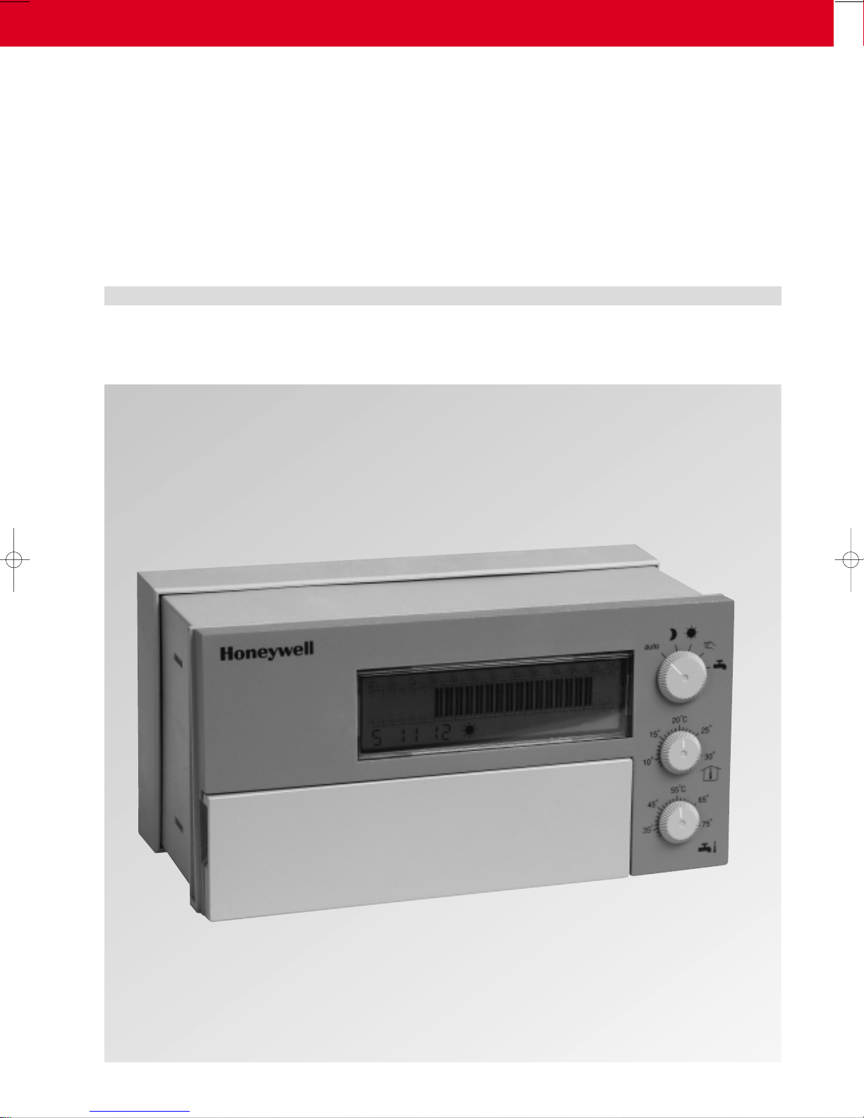
DIGITAL DISTRICT HEATING CONTROLLER DHC 23
FOR ORIGINAL EQUIPMENT MANUFACTURERS
OPERATING INSTRUCTIONS
Page 2

CONTENTS DHC 23
Short description 1
Safety notes 2
Operating elements 5
Operation by the user 6
Select operating mode 6
Select temperatures 7
LCD display 8
Adjustment by the user 9
Programming switch 9
Push and turn knob 9
Change switching times 10
Delete switching times 11
Service by the heating specialist 12
Basic settings 12
General functions and operating parameters 12
Special functions and operating parameters for DHC 23-1 14
Special functions and operating parameters for DHC 23-2 15
Special functions and operating parameters for DHC 23-3 15
Adaptation to district heating system 15
Restore basic adjustment 16
Correct the time 16
Battery change 16
Changes of the basic setting 17
Overview of operating parameters DHC 23-1 17
Overview of further operating parameters DHC 23-1 18
Overview of operating parameters DHC 23-2 19
Overview of further operating parameters DHC 23-2 20
Overview of operating parameters DHC 23-3 21
Overview of further operating parameters DHC 23-3 22
Troubleshooting 23
Sensor detection 23
Maintenance and cleaning 23
What to do if it becomes too warm? 23
What to do if it does not become warm? 24
Error messages of the DHC 23 25
Remote control TF 26 26
Connection for remote control TF 26 26
Technical data 27
Page 3
DHC 23 SHORT DESCRIPTION
■■
The DHC 23 is a digital controller for district heating systems. It has the complete
intelligence which is required for optimum control of a modern district heating system.
Properties of the DHC 23
Main functions
Simple Operation
Simple setting
Simple commissioning
Service freindliness
n Outside temperature compensated time-dependent flow temperature control
n Domestic hot water temperature control
n Heat-up optimization
n Demand dependent pump switching
n Automatic preventive maintenance operation etc.
Clear arrangement of the operating elements on the front ensure simple
operation.
The remote control TF 26 can be connected to the DHC 23 to operate it
conveniently from the living room.
A patented "Push and turn technique" facilitates simple setting.
Date and time are preset in the factory, as well as the following switching times:
Hot water is heated from 6.00 to 22.00,
the heating is on from 6.00 to 22.00.
All essential operating parameters can be displayed and changed simple.
1
Page 4

SAFETY NOTES DHC 23
Outside temperature compensated
flow temperature control
Heat-up optimization
Night-time cut-off
Frost protection function
Sensor detection
Domestic hot water priority
Maximum limitation of the district
heating return temperature
Interval flushing
■■
The flow temperature is controlled according to the heat requirement high enough so
that the wanted setpoints of the domestic hot water and of the room temperature are
reached. The room temperature can be regulated accurately using the thermostats
fitted to the radiators.
The DHC 23 selects the latest possible start of the temperature rise so that the required
room temperature is already reached at the set time.
The room temperature is lowered to a programmable value (night setpoint) in the night
during the heating period.
The pipelines are protected against freezing in that if there is a risk of frost, the heating
water circulates. The frost protection function is always active.
The connected sensors are detected and the type of control set to them automatically.
Sensor defects such as line breaks or short circuits are displayed.
The domestic hot water priority guarantees that the domestic hot water has its desired
temperature constantly in the times of domestic hot water readiness. An additional
interruption of the domestic hot water priority is possible.
The DHC 23 limits the return temperature to the value prescribed by the district heating
station.
To enable a temperature measurement in the return even with closed district heating
valve, the district heating valve is opened briefly every 10 minutes when heat is
required.
Automatic funktions of the DHC 23
Automatic pump preventive
maintenance operation
Summer/winter time change
Data protection
2
To avoid the heating circuit pump seizing, it is switched on daily for 1 minute.
The change from summer to winter time is automatic exactly at the correct time.
All data are protected by a battery against a power failure.
Further information on the functions and operating parameters is provided in the
Service by the heating specialist chapter.
Page 5

DHC 23 SAFETY NOTES
■■
The DHC 23 is designed exclusively for regulating and controlling district heating
systems including domestic hot water heating which do not exceed a maximum flow
temperature of 120 °C.
■■
1. The district heating system must be ready and filled with water so that the pumps
do not run dry.
2. The control device must be installed according to the installation instructions.
3. All electrical connections (power supply, valve actuators, pumps, sensor wiring, etc.)
must be made by the specialist according to the valid VDE regulations and
correspond to the corresponding circuit diagrams (see installation instructions).
4. If an underfloor heating system is connected, a limiting thermostat must be installed
by the customer in addition in the flow line after the heating circuit pump to switch
the pump off at too high flow temperatures.
If all these conditions are fulfilled (have them checked by the heating
specialist), the controller can be put into service.
The current time and date are already set in the factory and protected by a battery.
The timer works according to a basic program and the control functions are preset for
customary district heating systems.
Purpose
Prerequisite for commissioning
3
Page 6

SAFETY NOTES DHC 23
!
⁄
Manual mode
Temperature setting on the DHC 23
!
Data protection
Frost protection function
⁄
■■
Note that in the following cases there is a risk of scalding at all domestic hot water
taps (kitchen, bathroom, etc.)! In these cases mix sufficient cold water.
In the manual mode, the domestic hot water can be heated up to the maximum
possible flow temperature. This mode is used especially if the DHC 23 should be
defective. However, the high domestic hot water temperatures can be avoided by
switching off the domestic hot water charging pump by hand using the switch on the
pump (if present).
Temperature setting on the DHC 23 The domestic hot water temperature can be
set on the DHC 23 up to 75 °C
■■
The battery for protecting all individual data is otherwise loaded and must be replaced
prematurely.
The frost protection function of the DHC 23 is otherwise put out of operation.
Domestic hot water temperature above 60 °C
Do not separate the DHC 23 from the power supply
4
Page 7
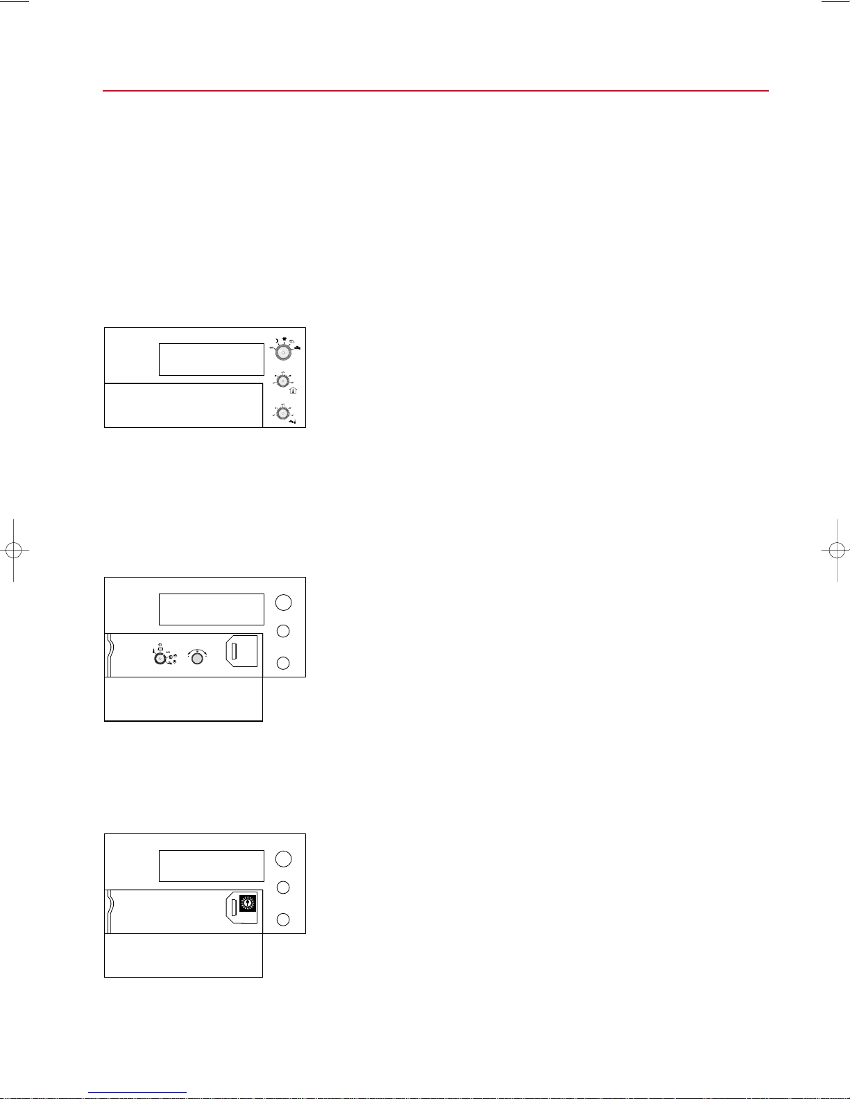
DHC 23 OPERATING ELEMENTS
To be able to handle the district heating controller DHC 23 well, it is divided into 3
operating levels:
1st operating level:
2nd operating level:
■■
In this level the user sets the basic heating functions. The operating elements required
for this are fitted on the front.
Operating mode switch:
The operating mode of the DHC 23 can be selected with the operating mode switch
(e.g. "Normal operation").
Room temperature set knob:
The room temperature can be selected with this knob.
Domestic hot water temperature set knob:
The domestic hot water temperature can be selected with this knob.
■■
In this level the user can make an individual change to the basic factory setting.
Grasp the recessed grip on the left behind the flap, pull it slightly and open the flap
downwards. The following operating elements are fitted behind it:
Programming switch
With the programming switch you can select whether heating times or times for
domestic hot water readiness should be changed.
Push and turn knob
With the push and turn knob you can (in combination with the programming switch)
change the heating times or the times of domestic hot water readiness..
Operation by the user
Adjustment by the user
3rd operating level:
■■
In this level the service personnel can perform service and maintenance work. The
operating element required for this, the service switch, is fitted behind the cover.
Service switch
With the service switch, the service personnel (in combination with the programming
switch) can check and change the operating parameters of the DHC 23.
Service by the heating specalist
5
Page 8

OPERATION BY THE USER DHC 23
Operating mode switch
■■
The operating modes of the DHC 23 can be set with the operating mode switch.
The meaning of the individual positions is illustrated by symbols.
Normal mode
Heating and domestic hot water readiness are switched on corresponding to
the set switching times. The set room temperature is assured at the set heating
times.
The domestic hot water has the set temperature in the times of domestic hot
water readiness.
Off mode
Heating and domestic hot water readiness are switched off. Frost protection for
the heating system is active. If there is risk of frost, a temperature corresponding
to the night set temperature value is regulated (reduced temperature). This
setting is practical for holidays, for instance.
Continuos heating mode
The heating is on right round the clock. Domestic hot water readiness is
switched on corresponding to the set switching times.
Select operating mode
6
Manual mode
For commissioning or for emergency operation.
Heating and domestic hot water are in uncontrolled continuous operation.
The pumps can be switched on and off provided a switch is fitted to the pumps.
The valve can be adjusted arbitrarily manually.
Domestic hot water readiness
Only domestic hot water readiness is switched on corresponding to the set
switching times. The heating is not on.
This setting is intended for the summer months.
Page 9
DHC 23 OPERATION BY THE USER
!
⁄
■■
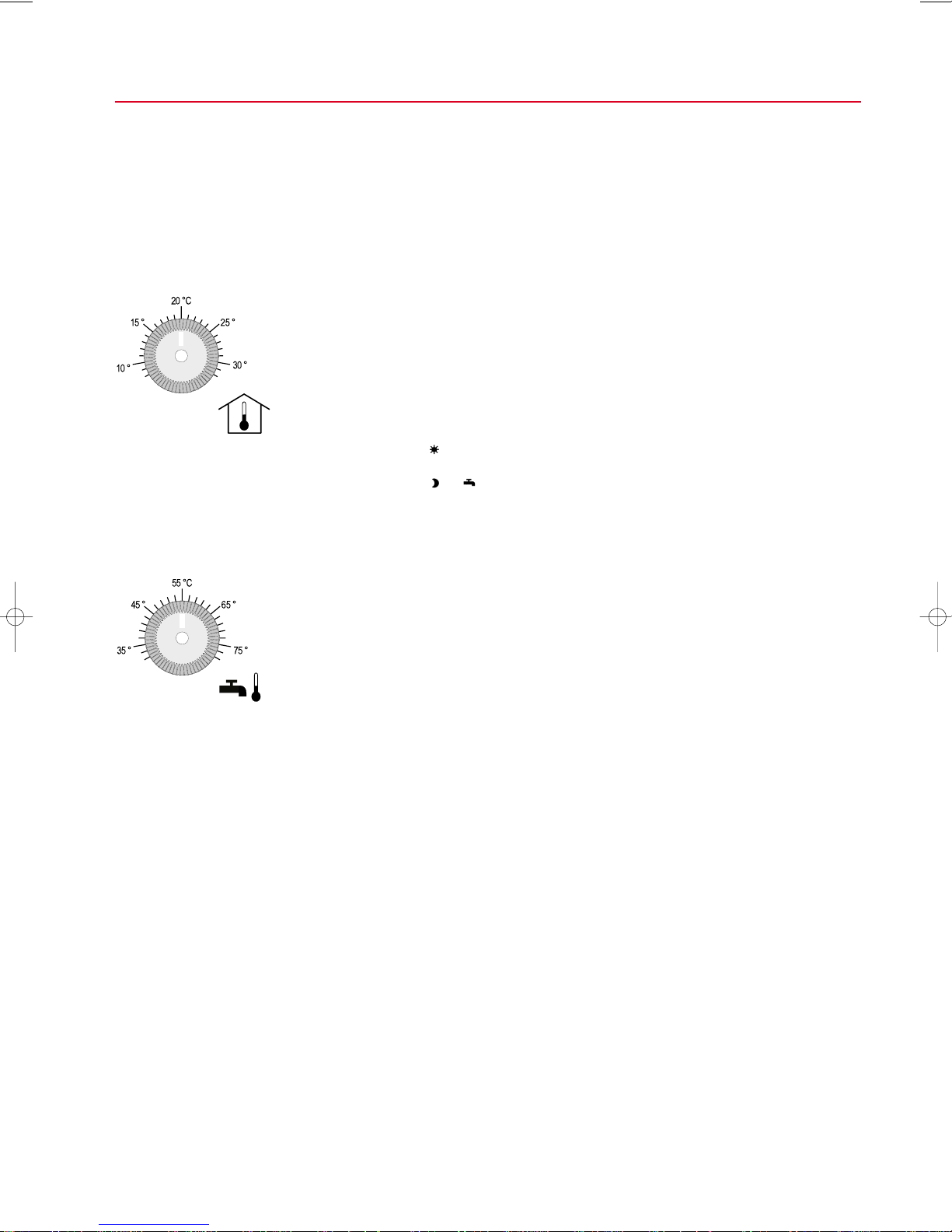
Select room temperature
The setpoint for the room temperature can be set with the aid of the room temperature
knob between 8°C and 32°C.
The room setpoint can also be set with the remote control TF 26.
In the normal operating mode, the set room temperature is maintained during the
set heating times, in the continuous heating mode constantly.
If you want to heat outside the set heating times, you must set the operating mode
switch to .
If you do not want to heat within the set heating times, you must set the operating mode
switch to or .
Select domestic hot water temperature
Warning:
With domestic hot water temperatures above 60°C there is danger of scalding at
all domestic hot water taps (kitchen, bathroom ...). You must then mix cold water
sufficiently.
The domestic hot water temperature can be set with the aid of the domestic hot water
temperature knob between 35°C and 75°C.
The set setpoint is always the cut-in value. The domestic hot water charging is
completed after reaching a switching difference (+ 5 K).
In the normal mode, continuous heating mode and domestic hot water rea-
diness modes, this temperature is controlled during the set times of domestic hot
water readiness, domestic hot water heating is switched off in between.
If you want to have domestic hot water at other times (e.g. early in the morning), you
must change the times of domestic hot water readiness (see Adjustment by the
user chapter).
Select temperatures
7
Page 10
OPERATION BY THE USER DHC 23
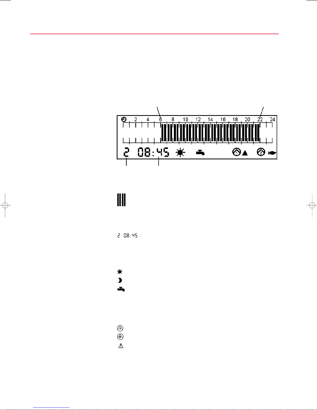
■■
Weekday current
(2 =Tuesday) time
If the operating mode switch is at auto, and you have not changed the switching times
set in the factory, the bars extend from 6.00 to 22.00. This means that the heating is on
continuously from 6.00 to 22.00.
LCD display
Heating is on continuously from 6.00 to 22.00
Bars of the heating times of the current day:
1 bar = 30 minutes heating
The weekday and the current time appear on the left below.
1 = Mo … 7 = Su
8
On the right next to the time, symbols show the operating state of the DHC 23 or
which parts of the system the DHC 23 is just controlling. The following symbols can
appear:
The heating is on currently.
The heating is off currently
The domestic hot water is currently being heated (domestic hot water
readiness).
▲ The district heating valve opens.
▼ The district heating valve closes.
The district heating valve is in neutral position (no triangular symbol).
The heating circuit pump is working.
The domestic hot water charging pump(s) works (work).
Caution: The DHC 23 has detected an error (see Error messages of the
DHC 23 section).
Page 11

DHC 23 ADJUSTMENT BY THE USER
Grasp the recessed grip on the left behind the flap, pull it slightly and open the flap
Programming switch
downwards. Two knobs are located behind it.
Push and turn knob
■■
The left knob is the programming switch, it has five positions.
The auto position is the normal position; this position is not used for adjusting the
system by the user.
In this position the switching times for the heating (heating times) can be set. 4 switching times (i.e. 2 periods) for heating are available for each individual weekday (see
Change switching times section).
In this position the switching times for domestic hot water readiness can be set. 4 switching times (i.e. 2 periods) are available for domestic hot water readiness for each individual weekday (see Change switching times section).
In this position the outside temperature is displayed; this position is not used by the
user for setting the system.
In this position the switching times of the circulation pump can be set..
■■
The right knob is the push and turn knob. It can be pushed and turned and is used for
changing the set values.
The values to be changed are selected by pushing and then flash. Flashing values can
be changed by turning. The change is temporarily stored by pushing once again.
Programming switch
Push and turn knob
9
Page 12

ADJUSTMENT BY THE USER DHC 23
■■
The DHC 23 is already equipped in the factory with a basic setting for the switching
times for heating and domestic hot water which satisfies normal requirements.
You can change this basic setting simply at any time.
1. Open the flap of the DHC 23.
2. Set the setting switch to , or according to whether you want to
change the switching times for heating, domestic hot water or circulation pump.
An A appears in the bottom left of the display (the switching times can be changed
simultaneously for all weekdays in this position) or a number of a weekday (1 = Mo
... 7 = Su). Black bars show the times in which the heating is on on the relevant
weekday (or domestic hot water readiness is switched on). The 1st cut-in time
appears instead of the current time.
Note:
Firstly make all changes which concern all weekdays (A). Only then make the
settings of the individual weekdays (weekdays 1 ... 7). Proceeding in the reverse
order has the effect that the setting of the individual weekdays is overwritten.
3. Now make the setting with the push and turn knob:
Push knob: A or the weekday flashes.
Turn knob: The weekday changes and continues to flash. Turn it until the
Push knob: The 1st cut-in time flashes, also the 1st bar in the display
Turn knob: The flashing bar moves along, at the same time the flashing
Push knob: The 1st cut-off time flashes, also the bar for cutting off and .
Turn knob: The flashing bar moves along, at the same time the flashing
The 2nd cut-in time and the 2nd cut-off time are determined by
Push knob: Then you must push the push and turn knob once again to
Caution:
If you set to auto, as long as a bar and a switching time are still flashing, the
previously changed switching times are not stored.
Perform this process until all required switching times are set.
4. Set the setting switch back to auto.
5. Close the flap again.
Change switching times
weekday to be changed flashes or A, if you want to change the
switching times affecting all weekdays.
and .
cut-in time changes in 10-minute steps.
cut-off time changes in 10-minute steps.
repeating this process (push knob, turn knob, push knob,
turn knob).
confirm all switching times, in this way the new cut-in and cut-off
times are stored in the DHC 23.
Programming switch
10
Page 13

DHC 23 ADJUSTMENT BY THE USER
■■
2 switching times are deleted by setting the cut-in time and cut-off time exactly equal,
i.e. 12:00 cut-in and 12:00 cut-off.
For this purpose simply move the cut-off bar over the cut-in bar.
After confirmation of all switching times, the deleted switching times are no longer displayed.
The deleted switching times become visible again by pushing and turning (to the right
or left).
Delete switching times
11
Page 14

SERVICE BY THE HEATING SPECIALIST DHC 23
Time and date
(Service switch position 0 and 1)
Maximum flow setpoint (2)
Night setpoint (3)
Frost protection limit (4)
Heating characteristic slope (5)
■■
The DHC 23 controller is preset in the factory with expedient control parameters.
These basic settings should cover a large part of the standard applications. However,
to be able to satisfy special requirements, it is additionally possible to adapt important
control parameters or functions.
■■
The following functions and operating parameters apply for all 3 DHC 23 types. The
number behind the described parameter (x) indicates the service switch position with
which the parameter can be selected. Bring the programming switch into the "auto"
position (normal position) for this. If the symbol appears behind the parameter
number "additionally", then the programming switch must previously be brought into
the position.
The current time and the current date were already set in the factory. Leap years are
taken into account automatically as well as summer and winter time.
The DHC 23 ensures that the setpoint of the flow temperature never exceeds the set
maximum value.
The room temperature is lowered during the heating period in the night to the set night
setpoint (night cut-off).
If the outside temperature drops below the frost protection limit, the heating circuit
pump is switched on.
According to outside temperature, a setpoint for the flow temperature between 20°C
and 90°C results through the heating characteristic. The heating characteristic slope
refers to -20°C outside temperature. The curvature of all heating characteristics is
uniformly 1.33.
The basic settings of the adaptable functions
General functions and operating parameters
Heat-up optmization (6)
Valve motor M 1 running time(7)
District heating valve minimum
liftl (A)
12
The heat-up optimization has the effect that the start of heating up of the heating system
is defined according to outside temperature so that the set room temperature is reached already at the set heating times.
This advancing of the heating up start depends upon the building construction:
Light construction = latest temperature rise start,
Heavy construction = earliest temperature rise start.
If a heat-up optimization should be performed, the building construction must therefore
be entered. "Light construction" should be entered for instance for a prefabricated
house, "heavy construction" e.g. for massive construction.
The valve motor running time is the time which the actuator needs to drive the district
heating valve from one end position (closed) to the other end position (open). The running time may have to be adapted only if motors other than the customary
HONEYWELL motors are connected.
Up to the set value, the DHC 23 works as two-point controller; this function simplifies
calorimetry in reduced load operation.
Page 15

DHC 23 SERVICE BY THE HEATING SPECIALIST
Maximum district heating return
temperature in heating mode (B),
onset point of floating district
heating return temperature
limitation. (C)
Some district heating utilities require minimum volume flows in their networks, this
can be achieved by a high temperature difference between flow and return. The
required temperature spread is assured by the maximum limitation of the district
heating return temperature. With the maximum limitation, both a fixed value limitation
can be performed and a floating limitation can be realized according to the outside
temperature by setting the parameters. Fixed value limitation to 50°C, for instance,
means that the district heating return temperature will not exceed this value over the
entire outside temperature range.
However, it is desirable at higher outside temperatures to shift this maximum limitation
downwards, i.e. to perform a floating district heating return temperature limitation. In this
way the lowest possible district heating return temperature is achieved, assigned to the
relevant outside temperature and thus good heat utilization.
The values for the maximum limitation of the remote heating return temperature and
the onset point of the floating remote heating return temperature limitation in heating
mode can be set, the floating return temperature limitation can be switched off by
selecting 10°C as onset point.
Return temperature onset point of the floating
limitation return temperature limitation
Example 1: 90 °C 10 °C factory setting
Example 2: 50 °C 10 °C Fixed value limitation
Example 3: 80 °C 5 °C
Example 4: 50 °C –10 °C
Reset time (D)
Controller gain(E)
Summer/winter time change
(D) + ( )
The reset time of the flow temperature controller can be adapted in critical systems.
The stability of the control is influenced by the controller gain. If the district heating
valve oscillates constantly open and closed, the controller gain must be set to a smaller
value. If the system takes too long until the room setpoint is reached, then the controller
gain should be increased.
The DHC 23 switches over automatically from summer to winter time. The change from
winter to summer time is made in the last weekend in March. The change back is
made in the last weekend in October. If the change-over dates should change, these
can be adapted.
13
Page 16

SERVICE BY THE HEATING SPECIALIST DHC 23
Overwrite TF 26 status (8)
Maximum inlet temperature in the
WW heat exchanger VF
Layered domestic hot water storage tank switching difference
(9) + ( )
Switching difference for domestic
hot water pump run-on (A) + ( )
Maximum district heating return
temperature with sole domestic hot
water charging (B) + ( )
Time interruption of domestic hot
water priority (C) + ( )
(9)
1
■■
Special functions and operating parameters
for DHC 23-1
If the DHC 23 is controlled at the input TW by a system other than the remote control
TF 26, it must be possible to ignore a signal applied at this input. Activating this
function has the effect that the applied signal is taken into account only up to the next
switching time and then ignored.
The inlet temperature in the external domestic hot water heat exchanger can be limited
upwards to prevent calcification. This function is active only in layered domestic hot
water storage tank operation (DHC 23-1).
In problematic systems, the switching difference between cut-in and cut-off temperature
can be changed.
This switching difference influences the duration of the charging pump run-on in
layered domestic hot water storage tank operation.
During domestic hot water charging, the return temperature limitation can be
cancelled. The higher values for the return temperature allowed for this special case
are determined here
The entry of 0 min. (time set in the factory) is treated as absolute domestic hot water
priority: The heating circuit pump is switched off as long as domestic hot water is being
charged. However, should the heating circuit cool down too much because of domestic
hot water charging, the DHC 23 can be set to interrupted domestic hot water priority by
changing the value from 0 min. (e.g. to 15 min.). The domestic hot water charging
pump and heating circuit pump then alternate and are operated in each case as long
as entered here (e.g. 15 min.).
14
Page 17

DHC 23 SERVICE BY THE HEATING SPECIALIST
Configuration of the 6th relay (9) + ( )
Layered heating circuit setpoint
(A) + ( )
Layered heating circuit heating
characteristic slope (B) + ( )
Temperature selector input (C) + ( )
Valve actuator M2 running time (8)
Reset time (9) + ( )
Controller gain (A) + ( )
Maximum district heating return
temperature with sole domestic
hot water charging (B ) + ( )
■■
Spezial functions and operating parameters
for DHC 23-2
The 6th relay can activate both the circulation pump and the pump of the layered heating circuit.
A separate room setpoint can be set for the layered heating circuit.
The heating characteristic slope for the layered heating circuit can be set separately.
Temperature selector input
The remote control TF 26 can act only on one heating circuit or both heating circuits
are operated through the remote control.t.
■■
Spezial functions and operating parameters
for DHC 23-3
The valve actuator running time is the time which the actuator needs to drive the valve
from one end position into the other end position "open". Only if actuators other than
the usual Honeywell motors are connected may the running time have to be adapted.
The reset time of the control circuit M2 can be adapted in critical systems.
The stability of the control is influenced by the controller gain. If the district heating
valve oscillates constantly open and closed, the controller gain must be set to a smaller
value. If the system requires too long until the room setpoint is reached, then the
controller gain should be increased.
The return temperature limitation can be cancelled during domestic hot water charging.
The higher value for the return temperature allowed for this special case is determined
here.
Programming switch
Service switch
Push and turn knob
■■
1. Open flap.
2. Withdraw cover.
Caution: Sensitive electronic components are located behind the cover.
Do not handle with objects inside the unit..
3. Bring the programming switch into the auto or. position.
4. Bring the service switch into the required position with a small screwdriver. The
position of the service switch and the value of the associated operating parameter
appear in the display instead of the weekday and the time.
5. Now make the change with the push and turn knob:
Push knob: The corresponding value flashes in the display.
. Turn knob: The value changes and can be adapted.
Push knob: The values flashes no longer and is adapted.
6. Bring the service switch back to 0 position. Thus the weekday and the current time
are displayed again during operation.
7. Reattach the cover.
8. Close the flap again.
Adaption to district heating system
Note: To change the year (service switch in position 1) push the
knob 2 times: After the first push the day and month can be changed, after the second push the year
15
Page 18

SERVICE BY THE HEATING SPECIALIST DHC 23
Push and turn knob
Programming switch
!
⁄
■■
Warning: All individual adaptations to the district heating system are lost when the
factory basic setting is restored.
Proceed as follows to restore the basic factory setting:
1. Open the flap of the DHC 23.
2. Switch off the power supply.
3. Switch the power supply back on with the push and turn knob pushed.
4. Release the push and turn knob.
The number 13 flashes in the display on the left below as error message.
5. Turn the programming switch to and back again to delete the error display
6. Close the flap.
If the basic factory setting is restored, any faults on the connected inputs are displayed
as error messages.
■■
If the clock becomes fast or slow in the course of the years, it can be set:
1. Open the flap of the DHC 23.
Note: The programming switch must stand at auto.
2. The time is now corrected with the push and turn knob:
Push knob: Time flashes
Turn knob: Correct time.
Push knob: Time no longer flashes and is corrected.
3. Close the flap again.
Restore basic setting
Correct the time
!
⁄
Service switch
16
■■
Warning:
Do not separate the DHC 23 from the mains during the battery change, otherwise all
individual data are lost.
The battery serves for storing the set data in the case of a power failure. So that no
data are lost on a power supply failure even after a lengthy operating time of the DHC
23, it is recommended that the battery is changed as a precaution every 8-10 years.
1. Open the flap of the DHC 23.
2. Withdraw the cover.
Caution:
There are sensitive electronic components behind the cover. Do not handle with
objects in the interior of the unit.
You will find the battery on the left behind the cover (button cell).
3. Withdraw the old battery and insert a new battery with the plus pole (+) to the left.
Battery type: CR 2032 3 V (e.g. Varta, Panasonic).
4. Reattach the cover.
5. Close the flap.
Battery change
Page 19

DHC 23 SERVICE BY THE HEATING SPECIALIST
Programming switch
Service switch
Push and turn knob
■■
It is possible to adapt important control parameters or functions for service purposes as
well as for adapting to special requirements. Proceed as follows:
Turn programming switch into auto position.
q
Different values can be displayed by turning the service switch into the positions
w
0 ... F (see Table).
The parameters can then be changed with the aid of the push and turn knob..
e
■■
Position Operating parameter Range Basic setting
0 Time 0:00...23:59 current time
1 Day, month or year 1990...2089 current date
2 Max. flow setpoint 30 ... 120°C 90°C
3 Night setpoint 0...20°C 10°C
4 Frost protection limit -10...15°C 2°C
5 Heating characteristic slope 0.4...4.5 1.6
6 Building construction
7 Valve actuator M1 running time 10...1800 s 120 s
8 Overwrite TF 26 status 0,1 0
9 Max. inlet temperature in * 40...90°C 90°C
A = 10 District heating valve minimum lift 0...30 % 0 %
B = 11 Maximum district heating return 40...90°C 90°C
C = 12 Onset point of floating distant -20...10°C 10°C
D = 13 Reset time 1...30 min. 3 min.
E = 14 Controller gain 1...30%/K 3 %/K
F = 15 (not used)
* Valid only for layered domestic hot water storage tank operation
Changes of the basic setting
Overview of operating parameters DHC 23-1
for optimization 0, 1, 2, 3 0
0 = optimization off
1 = light construction
2 = medium construction
3 = heavy construction
0 = do not overwrite
1 = overwrite
}
1
M 1
)
WW heat exchanger (VF
temperature in heating mode
heating return temperature limitation
17
Page 20

SERVICE BY THE HEATING SPECIALIST DHC 23
Programming switch
Service switch
Push and turn knob
■■
Turn programming switch into position.
q
Further parameters can be displayed and changed by turning the service switch
w
into the positions 9....D.
The parameters can then be changed with the aid of the push and turn knob.
e
Position Operating parameter Range Basic setting
0 Outside temperature only display
1 Flow temperature only display
2 District heating return temperature only display
3 Domestic hot water temperature upper* only display
4 Domestic hot water temperature lower* only display
5 Domestic hot water charging temperature* only display
6 Room temperature setpoint only display
7 Flow temperature setpoint only display
8 Maximum setpoint of the district only display
9 Layered domestic hot water
A = 10 Switching difference for* 0...10 K 1 K
B = 11 Maximum district heating return 40...90°C 90°C
C = 12 Absolute priority 0 min. 0 min.
D = 13 Automatic summer/winter time 05:03/05:10
E = 14 Current valve position M1 only display
F = 15 Software version
* Only for layered domestic hot water storage tank operation
Overview of further operating parameters DHC 23-1
heating return temperature
storage tank switching -10...20 K 0°C
difference* WW1 and WW2
domestic hot water pump run-on
temperature with sole domestic
hot water charging
time interruption of hot water priority 1...30 min.
parallel mode 40
18
Page 21

DHC 23 SERVICE BY THE HEATING SPECIALIST
Programming switch
Service switch
Push and turn knob
■■
Turn programming switch into auto position..
q
Different values can be displayed by turning the service switch into the positions
w
0 ... F (see Table).
The parameters can then be changed with the aid of the push and turn knob.
e
■■
Position Operating parameter Range Basic setting
0 Time 0:00...23:59 current time
1 Day, month or year 1990...2089 current date
2 Max. flow setpoint 30 ... 120°C 90°C
3 Night setpoint 0...20°C 10°C
4 Frost protection limit -10...15°C 2°C
5 Heating characteristic slope 0.4...4.5 1.6
6 Building construction
7 Valve actuator M1 running time 10...1800 s 120 s
8 Valve actuator M2 running time 10...1800 s 30 s
9 Max. inlet temperature in * 40...90°C 90°C
A = 10 District heating valve minimum lift 0...30 % 0 %
B = 11 Maximum district heating return 40...90°C 90°C
C = 12 Onset point of floating district -20...10°C 10°C
D = 13 Reset time 1...30 min. 3 min.
E = 14 Controller gain 1...30%/K 3 %/K
F = 15 (not used)
* Only for layered domestic hot water storage tank operation
Overview of operating parameters DHC 23-2
Overview of operating parameters DHC 23-2
for optimization 0, 1, 2, 3 0
0 = optimization off
1 = light construction
2 = medium construction
3 = heavy construction
}
)
1
M 1
WW heat exchanger (VF
temperature in heating mode
heating return temperature limitation
19
Page 22

SERVICE BY THE HEATING SPECIALIST DHC 23
Programming switch
Service switch
Push and turn knob
■■
Turn programming switch into position.
q
Further parameters can be displayed and changed by turning the service switch
w
into the positions 9....D.
The parameters can then be changed with the aid of the push and turn knob..
e
Position Operating parameter Range Basic setting
0 Outside temperature only display
1 Flow temperature of the only display
2 District heating return temperature only display
3 Domestic hot water temperature only display
4 Flow temperature unmixed circuit only display
5 Flow temperature setpoint
6 Room temperature setpoint only display
7 Flow temperature setpoint
8 Maximum setpoint of the district only display
9 Configuration of 6th relay 2, 3 3
A = 10 Room setpoint for layered
B = 11 Heating characteristic slope
C = 12 Temperature selector input 1...3 1
D = 13 Automatic summer/winter time
E = 14 Current valve position M1 only display
F = 15 Software version only display
Overview of further operating parameters DHC 23-2
heating circuit M1
mixed circuit only display
unmixed circuit only display
heating return temperature
2 = circulation pump
3 = layered heating circuit
heating circuit 8...32 °C 20
unmixed heating circuit 0.4...4.5 1.6
1 = acts on both heating circuits
2 = acts only on mixed heating circuit
3 = acts only on unmixed heating circuit
can be switched off 05:03/05:10
20
Page 23

DHC 23 SERVICE BY THE HEATING SPECIALIST
Programming switch
Service switch
Push and turn knob
■■
Turn programming switch into auto position.
q
Different values can be displayed by turning the service switch into the positions
w
0 ... F (see Table).
The parameters can then be changed with the aid of the push and turn knob.
e
Position Operating parameter Range Basic setting
0 Time 0:00...23:59 current time
1 Day, month or year 1990...2089 current date
2 Max. flow setpoint 30 ... 120°C 90°C
3 Night setpoint 0...20°C 10°C
4 Frost protection limit -10...15°C 2°C
5 Heating characteristic slope 0.4...4.5 1.6
6 Building construction
7 Valve actuator M1 running time 10...1800 s 120 s
8 Valve actuator M2 running time 10...1800 s 30 s
9 Max. inlet temperature in
A = 10 District heating valve minimum lift 0...30 % 0 %
B = 11 Maximum district heating return
C = 12 Onset point of floating district
D = 13 Reset time 1...30 min. 3 min.
E = 14 Controller gain 1...30%/K 3 %/K
F = 15 (not used)
Overview of operating parameters DHC 23-3
for optimization 0, 1, 2, 3 0
0 = optimization off
1 = light construction
2 = medium construction
3 = heavy construction
WW heat exchanger (VF
temperature in heating mode 40...90°C 90°C
heating return temperature limitation -20...10°C 10°C
) 40...90°C 90°C
1
M 1
}
21
Page 24

SERVICE BY THE HEATING SPECIALIST DHC 23
Programming switch
Service switch
Push and turn knob
■■
Turn programming switch into position.
q
Further parameters can be displayed and changed by turning the service switch
w
into the positions 9....D.
The parameters can then be changed with the aid of the push and turn knob
e
Position Operating parameter Range Basic setting
0 Outside temperature only display
1 Flow temperature of the only display
2 District heating return temperature only display
3 Domestic hot water flow only display
4 Flow temperature only display
5 Return temperature only display
6 Room temperature setpoint only display
7 Flow temperature setpoint only display
8 Maximum setpoint of the district only display
9 Reset time * 0...1800 s 0 s
A = 10 Controller gain 0.1...30.0%/K 10.0 %/K
B = 11 Maximum district heating
C = 12 Valve actuator M2 configuration 0, 1, 2 2
D = 13 Automatic summer/winter time
E = 14 Valve position only display
F = 15 Absolute priority 0 min. 0 min.
* < 1 s only P control no I component
Overview of further operating parameters DHC 23-3
heating circuit M1
heating return temperature
M 2
}
return temperature only for
domestic hot water charging 40...90°C 90°C
0 = modulating (2-10V)
1 = 3-point
2 = both parallel
can be switched off 05:03/05:10
time interruption of hot water priority 1...30 min.
parallel mode 40
22
Page 25

DHC 23 SERVICE BY THE HEATING SPECIALIST
Causes
Operating mode switch is not on
auto.
The heating characteristic setting
is not adapted optimally to the
building.
Remote heating remains open, alt-
▼
hough
Domestic hot water temperature
too high.
appears in the display.
■■
The DHC 23 detects which inputs are occupied, i.e. which sensors are connected and
automatically adopts the type of control to them.
■■
The DHC 23 is maintenance-free. The unit can be cleaned on the outside with a damp
(not wet) cloth.
■■
Measures
Set the operating mode switch to auto.
Have the heating characteristic changed by the heating specialist.
Possibly the electrical connection to the actuator of the remote heating valve is interrupted: Call heating specialist.
– Set domestic hot water temperature knob lower or
– Turn operating mode switch from to auto !
Sensor detection
Maintenance and cleaning
What to do if it becomes too warm?
23
Page 26

TROUBLESHOOTING DHC 23
Causes
Operating mode switch is not on
auto.
.appears in the display
Pumps does not run although
appears in the display of the
DHC 23
District heating valve remains
closed, although
display.
No line voltage.
The entire district heating system
is out of operation.
▲
appears in the
■■
Measures
Set the operating mode switch to auto.
Select the operating mode on the DHC 23 or, if present, on the remote control TF
26. For daily heating at this time, change the switching times of the DHC 23, see Chan-
ge switching times section
Check the fuse and separate switch on or for the pump. If fuse and switch in order, call
the heating specialist..
Call the heating specialist. To bridge over set the operating mode switch to .The
district heating valve can be adjusted manually..
Caution:
The domestic hot water temperature can be heated up to the maximum possible flow temperature! Mix cold water at the taps or switch the domestic hot water
charging pump off.
Check the heating main switch. Check the fuses.
What to do if it does not become warm?
Data loss of the DHC 23.
!
⁄
display flashes and "13"
The
flashes instead of the weekday
The heating characteristic setting
is not adapted optimally to the
building.
Due to an internal unit error or a discharged battery, the current time is disturbed and
the basic factory setting is valid again. Delete the error display (see Error messages
of the DHC 23 section). Enter the current time again (see Correct the time section)
and as required your wanted switching times again (see Change switching times
section). Have the values for adapting to your district heating system as well as the
battery checked by the heating specialist
Have the heating characteristic changed by the heating specialist.
24
Page 27

DHC 23 TROUBLESHOOTING
Error numbers of the DHC 23
Delete error display
■■
Sensor defects such as line breaks or short-circuits are detected automatically if the
Installation chapter was followed exactly during installation. If the service switch is at
position 0 and the programming switch at auto, the display
error and at the same time an error number instead of the weekday display.
1 (not used)
2 (not used)
3 (not used)
4 (not used)
5 Return temperature sensor faulty
6 Flow temperature sensor faulty
7 Outside temperature sensor faulty
8 Cable to the remote control TF 26 interrupted
9 Domestic hot water temperature sensor faulty at the cut-off point
10 Domestic hot water temperature sensor faulty
11 Domestic hot water flow temperature sensor faulty
12 Connection between two DHC 23 faulty
13 The basic factory setting has been restored
In the case of errors, the corresponding input is considered as not connected and the
associated control circuit is put out of operation.
To delete an error display, turn the programming switch to and back to auto. Only
rectified errors are deleted, errors not rectified continue to be displayed.
Error messages of the DHC 23
!
⁄
flashes in the case of
25
Page 28

REMOTE CONTROL TF 26 DHC 23
■■
The most important function of the DHC 23 can be remotely controlled from the living
room with the comfortable remote control TF 26:
– Set setpoint for the room temperature
– Switch heating on or off
auto Heating and domestic hot water readiness are switched on corresponding
The setting of the remote control TF 26 is added to the setting on the DHC 23. For
instance, if 19°C is set as setpoint on the DHC 23 and +2 K on the remote control, then
an effective setpoint of 21°C results.
Connection for remote control TF 26
to the set switching times. The room temperature is reduced to the night
setpoint during the night (night shutdown).
The heating is on round the clock. Domestic hot water readiness is switched
on corresponding to the set switching times.
Heating is off. Domestic hot water readiness is switched on corresponding to
the set switching times.
Knob for the room temperature setpoint, effective only in the and auto
position of the TF 26 operating mode switch.
Setting range: –7. . . +7 K
Mid position: 0 K
Connection of TF 26
to DHC 23
26
Page 29

DHC 23 TECHNICAL DATA
■■
Control system Microprocessor control with analogue operation
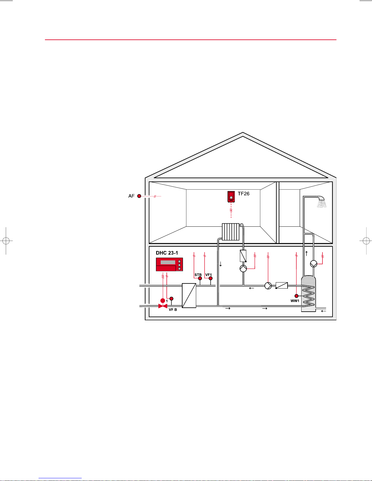
Type designation DHC 23
Order designation DHC 23-1: One heating circuit, optionally one domestic hot water circuit
Construction Digital controller in impact-proof plastic housing, plug-in unit base with screw
Version Corresponding to DIN 32 729
Controller type PI controller
Default switching times Heating times: daily 6.00 until 22.00
Automatic preventive maintenance Heating circuit pump: daily 10.00, 1 min.
operation
Summer/winter time changeover Start of summer time: last Sunday in March, 2.00 (1 hour forwards)
Supply voltage 230 V AC + 6 % ... -15 % 50...60 Hz
Power consumption 5 W
Data protection Individual data protection (eg. during power failure) by an exchangeable battery for up
Protection standard IP 30 according to EN 60529
Protection class II according to EN 60730-1
Radio interference conformity
Dimensions 192 x 96 mm (W x H according to DIN 43700) x 98 mm (D)
Control panel cut-out 186+1.1 x 92+0.8 mm
Weight approx. 950 g without packaging
Mounting Wall mounting or control panel front installation with control panel installation set ER 9
Terminals Screw terminals, max. cable cross-section 1.5 mm
Storage temperature -20°C...+65°C
Operating temperature 0...40°C
Relativet humidity 5...70 %
Technical data
DHC 23-2: One mixed heating circuit, optionally one unmixed heating circuit,
or domestic hot water control
DHC 23-3: Nordic standard domestic hot water circuit with fast response
heat exchanger, optionally one heating circuit.
terminals
Corresponding to draft AGFW Memorandum "Requirements on outside temperature
compensated control devices"
Domestic hot water availability: daily 6.00 until 22.00
Start of winter time: last Sunday in October, 3.00 h (1 hour back)
2 years continuously, thereafter a maximum of 48 hours per year (at 20°C)
according to EN 50 081-1 and EN 50 082-1
2
27
Page 30

TECHNICAL DATA DHC 23
Battery type CR 2032, 3 V, 170 mAh
Manufacturer: e.g. Varta, Panasonic
Inputs Maximum 6 temperature sensor inputs
Honeywell NTC 20 kΩ series
Remote setpoint unit TF 26
Outputs Floating outputs depending on DHC 23 type:
One floating output for primary District Heating valve actuator (relay 230 Vac; 0.6 A)
Second floating output for valve actuator (relay 230 Vac; 3 (1) A)
DHC 23-3 only:
The second valve actuator output can either be floating (relay) or modulating (2–10 V),
adjustable by software during start-up.
Binary outputs depending on DHC 23 type:
Maximum 4 relay outputs for pump control; 230 Vac; 3 (1) A.
Maximum current over all relays: 8 A.
Temperature diagnostic output
TTL level; transfer over RS 232 with separate adapter.
Sensor cables For troublefree operation we recommend using shielded sensor cables. The cable
cross-section should be at least 0.75 mm
Accessories Wall socket DHC 23-WS
2
, for 230 V AC at least 1.5 mm2.
28
Page 31

H
Home and Building Control Products
Honeywell AG
Böblinger Strasse 17
D-71101 Schönaich
Phone: (+49) 7031 637-01
Fax: (+49) 70 31637- 4 93
http://europe.hbc.honeywell.com
EN2B-160 GE51R0999 Subject to change without notice. Printed in Germany
s
 Loading...