

Page 1
Dehumidification
69-1951
Fresh Air Ventilation
Compact Size
Energy Efficient
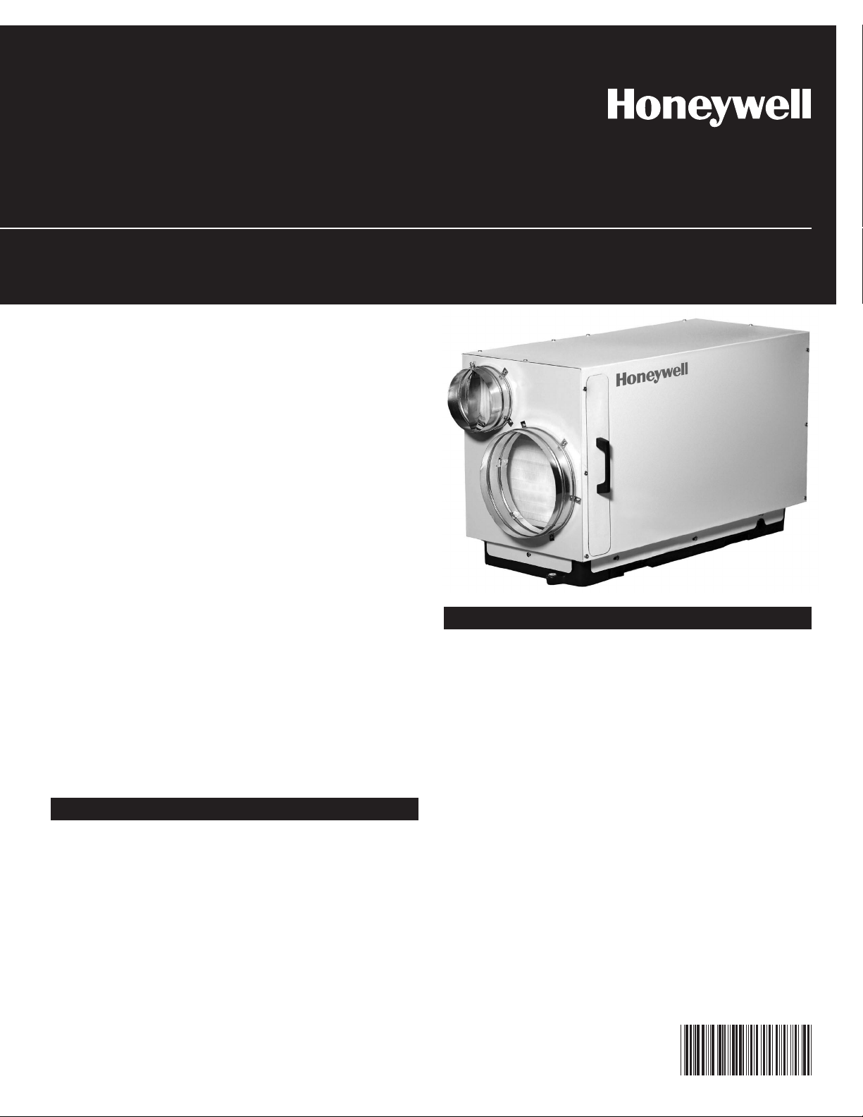
The DH90 whole house dehumidifier integrates
high-capacity dehumidification, fresh air ventilation, and filtration, into a compact and easy to
install enclosure.
DH90 Whole House Dehumidifier
with fresh air ventilation
Installation Guide
Fresh Air Ventilation (optional)
An automatic ventilation controller and dehumidistat are included.
The dehumidifier removes 90 pints of water from
the air per day (80F, 60% RH) while only using 6.2
Amps of electricity.
The high moisture removal capacity helps maintain proper levels of humidity in most homes.
Dehumidification
The DH90's high efficiency refrigeration system is
further enhanced with a heat exchanger to achieve
exceptional performance while keeping your energy
costs as low as possible.
HVAC Installer: Please leave manual for homeowner.
® U.S. Registered Trademark.
Copyright © 2006 Honeywell International Inc.
All rights reserved.
Fresh air may be ducted to the unit and regulated
using the provided Honeywell W8150 fresh air
ventilation controller along with the optional
EARD6 damper.
Page 2

DH90 Dehumidifier • For HVAC Installer Only
Table of Contents
Introduction . . . . . . . . . . . . . . . . . . . . . . . 1
Features & Benefits . . . . . . . . . . . . . . . . . 1
Safety Precautions . . . . . . . . . . . . . . . . . . 2
1. Intended Application . . . . . . . . . . . . . . . . 3
2. Approvals . . . . . . . . . . . . . . . . . . . . . . . . . 3
3. Specifications . . . . . . . . . . . . . . . . . . . . . . 3
4. Installation . . . . . . . . . . . . . . . . . . . . . . . . 3
4.1 Installation Checklist . . . . . . . . . . . . . 3
4.1A Power Accessibility . . . . . . . . . . 3
4.1B Accessibility . . . . . . . . . . . . . . . 3
4.1C Support Structure and
Suspension . . . . . . . . . . . . . . . . 3
4.1D Sizing Chart . . . . . . . . . . . . . . . 3
4.2 Electrical Requirements . . . . . . . . . . . 3
4.3 Condensate Removal . . . . . . . . . . . . 4
4.4 Ducting. . . . . . . . . . . . . . . . . . . . . . . . 4
4.4A Fresh Air / Supply Air . . . . . . . . 4
4.4B Ducting for Fresh Air—Option . . 5
4.4C Installation in a Basement or
Crawl Space with an Existing
Forced Air HVAC System . . . . . 5
4.4D Installation in an Attic with
an Existing Forced Air
HVAC System . . . . . . . . . . . . . . 6
4.4E Installation in a Structure with
Two Forced Air HVAC Systems . 6
4.5 Noise Abatement . . . . . . . . . . . . . . . . 7
5. Maintenance . . . . . . . . . . . . . . . . . . . . . . . 7
5.1 Air Filter . . . . . . . . . . . . . . . . . . . . . . . 7
5.2 Optional Fresh Air Intake . . . . . . . . . . 7
6. Wiring Diagrams . . . . . . . . . . . . . . . . . . . . 7
6.1 Choose correct wiring diagram . . . . . 8
7. Parts List . . . . . . . . . . . . . . . . . . . . . . . . . 9
8. Setting the Control . . . . . . . . . . . . . . . . . . 9
9. Service . . . . . . . . . . . . . . . . . . . . . . . . . . 10
9.1 Troubleshooting . . . . . . . . . . . . . . . . 10
9.2 Refrigerant Charging . . . . . . . . . . . . 11
9.3 Compressor/Capacitor
Replacement . . . . . . . . . . . . . . . . . . 11
Safety Precautions
Read the installation, operation and maintenance instructions carefully before installing and
operating this device. Proper adherence to these instructions is essential to obtain maximum benefit
from your DH90 indoor air quality system.
READ AND SAVE THESE INSTRUCTIONS
• The device is designed to be installed INDOORS IN A SPACE THAT IS PROTECTED
FROM RAIN AND FLOODING.
• Install the unit with space to access the front panel for maintenance and service.
• Avoid directing the discharge air at people, or over the water in pool areas.
• If used near a pool or spa; be certain there is NO chance the unit could fall into the water,
splashed and that it is plugged into a GFI GROUND FAULT INTERRUPT OUTLET.
• DO NOT place the device directly on structural members.
• A drain pan MUST be placed under the unit if installed above a living area or above an
area where water leakage could cause damage.
2
Page 3
For HVAC Installer Only • Installation Guide
1. Intended Application for DH90
The DH90 is intended for use in residential
applications to reduce the indoor humidity levels
and increase comfort. With the optional ventilation
ducting and ventilation control hookup, the device
also provides precise amounts of ventilation air.
2. Approvals
The DH90 is certified by ETL to meet UL 474 and
CSA 22.2 No. 92.
3. Specifications
Model: DH90
Electrical: 110-120 VAC, 6.2 Amps,
60 Hz, grounded
Capacity: 90 pints/day @ 80°F, 60%
RH
Inlet air temperature range: 55°F min., 100°F max.
Air Flow: 200 CFM without external
ducting
4.1A Power Accessibility
Unit should be located in an area where the cord’s
length (10') should easily reach a 115 VAC electrical
outlet with a minimum of a 15 A circuit capacity.
4.1B Accessibility
The installed DH90 should have at least 14 inches
of clearance in the front of the device to service
the filter.
4.1C Support Structure and Suspension
Place the DH90 on supports to raise the base of the
unit. Do not place the DH90 directly on structural
building members without vibration absorbers or
unwanted noise may result.
The DH90 may be suspended from structural
members by supporting the entire base of the unit
via cross members, rigid frame, or the like. Do not
hang the a DH90 from the cabinet. Remember to
place a drain pan under the unit if it is suspended
above a finished area or above an area where
water leakage could cause damage.
Refrigerant Charge: 1 lb., 12 oz. R22
Duct Connections: Round 10" inlet, 10"
outlet, 6" ventilation
inlet
Filter Size: Pleated MERV 11:
14" x 14" x 1"
Unit Size (w/o Duct Collars): 34.5"L x 15.75"W
x 20.875"H
Unit Weight: 92 lbs
Shipping Weight: 99 lbs
4. Installation
4.1 Installation Checklist
IMPORTANT: Prior to installation of the
DH90, the following checklist should be
reviewed.
The DH90 can be installed in a variety of locations
to meet the owner’s needs, and integrate with
existing forced air systems or existing ductwork
if desired. Choose a location with consideration
to accessibility for service, drain availability, and
power outlet location.
4.1D Sizing Chart
*This sizing chart is based on extreme climates where Rh levels
are between 70 and 90% outdoor Rh. For less extreme climates
then larger homes can be adequetely served. Actual requirements
may vary.
Dehumidifier Capacity Required to
Maintain Desired Indoor Rh*
Home Size
(square
feet)
2080 49-54 55-58 71-78
2600 61-68 65-72 90-97
3120 75-82 79-86 95-110
60% Indoor Rh55% Indoor Rh50% Indoor
Rh
Pints/day Pints/day Pints/day
4.2 Electrical Requirements
WARNING: Installation must be performed
by a qualified service technician and must
comply with local codes. Remove power to
the device before installing or servicing the
device. Failure to connect the device
according to these instructions may result in
damage to the device or the controls.
3
Page 4
DH90 Dehumidifier • For HVAC Installer Only
Fresh air intake
Supply air
Ducting to isolated areas
Indoor air
return
W8150
Controller
EARD6
Motorized
damper
The DH90 plugs into a common grounded 115VAC
outlet. The device draws 6.2 Amps under normal
operating conditions. If used in an area which
may become wet, a ground fault interrupter (GFI)
protected circuit is recommended.
IMPORTANT: Do not install the humidistat
where it may not accurately sense the relative
humidity such as near HVAC supply registers,
near exterior doors, on an outside wall, near a
window, or near a water source.
Refer to Section 6 for typical hookup diagrams.
Some of the control wires leaving the DH90 may
not be used with certain installations and should
be left unconnected with wire nuts taped onto the
stripped ends for safety.
4.3 Condensate (Water) Removal
The DH90 removes a large amount of moisture
from the air and the device must be connected to
a drain line that will carry away the excess water. A
trap in the drain line is recommended and may be
required by some local codes.
The drain line should be connected to the 3/4" male
pipe thread adaptor on the front of the DH90.
Care should be taken to install the drain line with
a continuous slope of 1" per 10' to assure proper
water removal.
4.4 Ducting
IMPORTANT: When connecting ventilation
duct, remove the label and 6" round
insulation plug from the ventilation duct
opening. If not using ventilation feature,
leave the insulation intact.
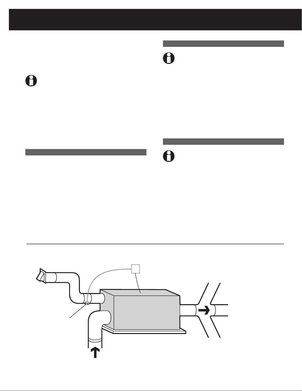
For the ideal installation, draw air from the central
part of the home and return it to the isolated areas
of the home like the bedrooms, den, utility room,
or family room. See Fig. 1. Alternative installation
option can be completed by drawing air directly
from the return ducting and distributing through
the supply air to the home.
4.4A Fresh Air / Supply Air
IMPORTANT: DO NOT draw air directly from
the kitchen, laundry, or isolated basement.
Air may be drawn from a basement that is open
to the home. All flexible ducting connected to the
DH90 should be UL listed.
A short piece of flexible ducting on all DH90 duct
connections is recommended to reduce noise
and vibration transmitted to rigid ductwork in the
structure. Ducting the DH90 as mentioned requires
consideration of the following points:
• Duct Sizing: For total duct lengths up to
25', use a minimum 10" diameter round or
Figure 1: Ducting to isolated areas.
4
Page 5

For HVAC Installer Only • Installation Guide
Dry air to basement
Fresh air
Inlet hood
EARD6
motorized
damper
Heating A/C supply air
W8150 Controller
Heating A/C
return air
Indoor
air return
equivalent rectangular. For longer lengths,
use a minimum 12" diameter or equivalent.
Grills or diffusers on the duct ends must
not excessively restrict airflow.
• Isolated Areas: Effective dehumidification
may require that ducting be branched to
isolated, stagnant air flow areas.
Use 8" or larger diameter branch ducting to each
of two or three areas, use 6" or larger to each of
four or more areas. Provisions must be made to
provide airflow from supply locations to central
return location. Proper air distribution is important
to ensure even humidity control throughout the
structure.
4.4B Ducting for Fresh Air — Option
Fresh air may be brought into the structure by
connecting an insulated duct from outside the
structure to the 6" inlet of the DH90. Advantages
of this form of ventilation include:
1. Outside air is filtered before entering the
building.
2. Outside air will be dehumidified before
entering if the DH90 is running in
dehumidification mode.
3. Drawing air from outside and blowing
inside aids in slightly pressurizing the
structure. This helps prevent dirty and
humid air from entering elsewhere.
Exhaust fans are recommended in the
bathrooms and kitchen.
An insulated 6" diameter duct is generally
sufficient to provide up to 75 CFM of outside air.
Large quantities of outside air will impact DH90
performance positively or negatively, depending
upon the inside and outside air conditions.
The outside air duct should be connected to the 6"
round collar on the side of the unit. The amount of
outside air can be restricted by the blade damper
in the 6" collar. The actual amount of ventilation
air being delivered through the ventilation ducts
must be measured in each installation. Refer to the
instructions provided with the W8150 Ventilation
Control for proper setup instructions.
4.4C Installation in a Basement or Crawl Space
with an Existing Forced Air HVAC System
Install a separate 10" return for the DH90 in a central
area of the structure. Optional: Duct the supply of
the DH90 to a 10" x 10" x 10" tee/damper, adjusted
to 20% open to the basement. Duct the other side
of the tee to the air supply of the existing HVAC
system with a backdraft damper. Connect a duct
from outside to the 6" collar of the DH90 if you
wish to provide ventilation air. See Figure 2.
Figure 2 : Basement or crawlspace installation.
5
Page 6

DH90 Dehumidifier • For HVAC Installer Only
Fresh air intake
W8150
Controller
Indoor air
supply
Indoor air
return
Indoor air
return
Supply air
Heating & A/C unit
EARD6
Motorized
damper
Figure 3 : Attic Installation.
Instead of installing a separate return to the DH90,
and if the existing system has multiple returns,
it is possible to select one to disconnect from
the existing forced air system and use it for the
dedicated DH90 return. Always select a return from
a central location in the structure in an area that is
always open to the rest of the structure. Do not use
a return from a room that may have its door closed
much of the time.
4.4D Installation in an Attic with an Existing
Forced Air HVAC System
IMPORTANT: ALWAYS install a catch pan
with a drain or float interrupt for condensate
under the DH90 in an attic or condensate
may damage the living space below.
The interrupt switch should be installed in series
with the field wire that connects the blue lead
from the DH90 to the dehumidistat. If overflow
occurs, this switch opens the compressor control
circuit and stops water production before the
catch pan overflows. The DH90 will continue to
ventilate or circulate air as normal, but will not
dehumidify until this switch closes.
6
The preferred method of installation is to create a
separate return for the DH90 in a central area of
the structure. Duct the supply of the DH90 to the
air supply of the existing HVAC system. Connect
an insulated duct from outside to the 6" collar of
the DH90 if you wish to provide fresh air. Adjust a
damper in the duct to provide the desired amount
of fresh air. See Figure 3.
4.4E Installation in a Structure with No Existing
Forced Air HVAC System
When installing the DH90 in a structure that does
not have a forced air HVAC system, a single return
for the DH90 should be installed in central open
area of the structure.
DO NOT locate the return in a bathroom or a
kitchen. The supplies of the DH90 should be
located in the remote areas of the structure (such
as bedrooms, den, etc.). By ducting this way, the
air inside the structure will circulate through the
DH90 to be filtered and dehumidified.
6" diameter duct is recommended for branches to
the bedrooms, 8" diameter duct is recommended
for branches to larger areas. Connect an insulated
duct from outside to the 6" collar of the DH90 if
you wish to provide ventilation. See Figure 4.
Page 7

Exhaust
Air
Fresh air
Inlet hood
Indoor air
return
EARD6
Motorized
damper
W8150
Controller
Figure 4 : Install with no forced air HVAC system.
Dehumidistat
DH90
24VAC for powered
Humidistat
H
u
m
id
it
y
C
o
n
t
r
ol
R
é
g
u
l
a
t
e
u
r
d
'h
u
mi
d
i
t
é
2
0
F
10
F
0
F
+
10
F
+
20
F
O
v
e
r
2
0
F
15
%
2
0
%
2
5
%
3
0
%
3
5
%
4
0
%
H
U
M
I
D
I
T
Y
S
E
T
T
IN
G
O
U
T
D
O
O
R
T
E
M
P
E
R
A
T
U
R
E
3
0
C
25
C
20
C
-
1
0
C
5
C
O
ve
r
0
C
White
Red
Yellow
Blue
Green
Dehumidistat
DH90
24vac for
Powered
Humidistat
Hu
m
i
d
i
ty
c
o
n
tr
ol
Ré
g
u
l
at
e
u
r
d
'h
u
m
i
d
i
té
20
f
10
f
0
f
+1
0
f
+2
0
f
o
v
e
r
2
0
f
15
%
20%
25
%
30
%
3
5%
4
0%
H
u
m
id
it
y
S
e
t
t
in
g
O
ut
d
o
o
r
T
e
m
p
e
r
a
t
u
r
e
3
0
c
25
c
20
c
10
c
5
c
o
v
e
r
0
c
White
Red
Yellow
Blue
Green
W8150A
Ventilation
Override
Switch
Ventilation damper
Damper
Remote
XFMR
R
C
DAMPERAUXREMOTE
4.5 Noise Abatement
A length of 10' or more of acoustical flex ducting
on the outlet of the DH90 will reduce air noise from
the fan. A length of flexible ducting on all DH90
duct connections is recommended to reduce noise
transmitted to rigid ductwork in the structure.
For HVAC Installer Only • Installation Guide
6. Wiring Diagrams
Figure 5 : Dehumidistat only—No fresh air ventilation.
5. Maintenance
5.1 Air Filter
The DH90 is equipped with a MERV 11 media
filter. This filter should be checked every three
months and replaced every six months. Operating
the unit with a dirty filter will reduce dehumidifier
capacity and efficiency and may cause the compressor to cycle off and on unnecessarily on the
defrost control.
CAUTION: Operate the unit only with a
genuine Honeywell filter installed to assure
proper performance of the unit.
5.2 Optional Fresh Air Intake
Check and clean the screen on the outdoor fresh
air intake port seasonally. The screen may become
plugged during the seasons when there are many
particles in the outdoor air.
Figure 6 : Dehumidistat including fresh air ventilation.
7
Page 8

DH90 Dehumidifier • For HVAC Installer Only
Wake
Room
System
Fan
Heat
Auto
AM
DST
Tue
R C W Y G
R RCW Y G
M19994
G
F
R
C
C
C
C
H
W
G
T
W8150A
HVAC
Wake
Room
System
Fan
Heat
Auto
AM
DST
Tue
W R
HVAC
COOLINGHEATING
R C C Y G
R RCW Y G
M19995A
G
F
R
C
C
C
C
H
W
G
T
NOTE:
REMOVE FACTORY
INSTALLED JUMPER
BETWEEN Cc AND CH
ON W8150.
W8150A
Wake
Room
System
Fan
Heat
Auto
AM
DST
Tue
W1CR W2Y1Y2G
W1CRCR W2Y1Y2G
M19996
G
F
R
C
C
C
C
H
W
G
T
HVAC
W8150A
Wake
Room
System
Fan
Heat
Auto
AM
DST
Tue
R C Y G O
RCR W Y G O/B
M19997A
G
F
R
C
C
C
C
H
W
G
T
HVAC
W8150A
6.1 Choose the correct wiring diagram based on HVAC system
Figure 7: Single transformer, conventional system.
Figure 8 : Dual transformer, conventional system.
Figure 9 : Multi-stage conventional system.
Figure 10: Wiring heat pump without emergency heat.
8
Page 9

Wake
Room
System
Fan
Heat
Auto
AM
DST
Tue
YCR W2 E G O
Y1W
1
CR W2E G O/B
M19998A
G
F
R
C
C
C
C
H
W
G
T
HVAC
W8150A
Figure 11: Wiring heat pump with emergency heat.
Honeywell
Golden Valley, MN 55422
50001159-001 Rev. A
W8150A 1001
1
www.honeywell.com/yourhome
or call 1-800-468-1502
_________
area (sq. ft.)
Record settings above
Ventilation Limit*
Ventilation
Standard
1260%
ASHRAE 62.2
100%
62-1999
Installer
Test
M19991A
Para español ver las instrucciones
*See Instructions Voir mode d'emploi en français inclus
R
C
DMP
DMP
AUX
AUX
REM
REM
24 VAC
XFRM
HVAC
Stat
Damper
ERV/Fan
Timer/Switch
GF
RC
CC
CH
W
GT
Patent Pending
_________
bedrooms
_________
airflow (cfm)
Date installed:________________________
W8150A 1001
_________
area (sq. ft.)
Record settings above
Ventilation Limit*
Ventilation
Standard
1260%
ASHRAE 62.2
100%
62-1999
Installer
Test
R
C
DMP
DMP
AUX
AUX
REM
REM
24 VAC
XFRM
HVAC
Stat
Damper
ERV/Fan
Timer/Switch
GF
RC
CC
CH
W
GT
_________
bedrooms
_________
airflow (cfm)
Date installed:________________________
7. Parts List
For replacement parts call: 1-800-345-6770.
For HVAC Installer Only • Installation Guide
TIPS:
• Ventilation control reads new dial setting only
when test button is pushed or power is cycled.
To ensure dial settings are read, push test
button after any changes are made.
• For single bedroom homes, set the bedrooms
dial to 2 (this may result in more ventilation than
the minimum required).
• For homes having more than five bedrooms
and only a single ventilation system, set the
bedrooms dial to 5 (this may result in less
ventilation than the minimum required).
• For conditioned square feet, set area (sq ft) dial
to the nearest value.
• For airflow, set airflow (cfm) dial to the nearest
value.
• Vaulted ceilings do not need to be considered
when setting this control.
• For homes with multiple systems: Honeywell
recommends a ventilation control and fresh
air intake for each system. Measure ventilation
airflow for each system independently. Refer to
Multi-system Setup Example for further details.
DH90A1007 — DH90 Dehumidifier
EARD6 — Motorized Damper
50018994-001 — 14" x 14" x 1" MERV 11 Filter
50018995-001 — 10" Back Draft Damper
8. Setting the control
1. Be sure power is turned on.
2. Set the Ventilation Standard on the control.
3. Set the bedrooms dial.
4. Set the area (sq ft) dial.
5. Set the airflow (cfm) dial.
6. Press the test button and observe the lights:
Green light is flashing.
The dial settings meet the chosen standard.
Red light is flashing.
There is not enough fresh air delivered
to meet the requirements of the selected
standard. See Troubleshooting section.
7. Record settings on the label inside the cover
as shown in the diagram.
9
Page 10

DH90 Dehumidifier • For HVAC Installer Only
9. Service
CAUTION: Servicing the DH90 with its high pressure refrigerant system and high voltage circuitry
presents a health hazard which could result in death, serious bodily injury, and/or property damage.
Service should only be performed by a qualified service technician.
9.1 Troubleshooting
No dehumidification, neither fan nor compressor
run with fan switch and ventilation timer OFF.
1. Unit unplugged or no power to outlet.
2. Humidity control set too high or defective.
3. Loose connection in internal or control wiring.
4. Defective Compressor relay.
5. Defective control transformer.
6. Low pressure control open.
7. Optional Condensate Pump Safety Switch
open.
No dehumidification, compressor does not run
but fan runs when there is a call for dehumidification and the ventilation control is OFF.
1. Defective compressor run capacitor.
2. Bad connection in compressor circuit.
3. Defective compressor overload.
4. Defective compressor.
5. Defrost thermostat open.
6. Optional Condensate Pump Safety Switch
open.
Fan runs when there is a call for dehumidification and the ventilation control is OFF, but the
compressor cycles on and off too frequently.
1. Low ambient temperature and/or humidity
causing unit to cycle through defrost mode.
2. Defective compressor overload.
3. Defective compressor.
4. Defrost thermostat defective.
5. Dirty air filter(s) or airflow restricted.
6. Low refrigerant charge, causing defrost
control to cycle.
7. Bad connection in compressor circuit.
Fan does not run with fan switch in either
position.
10
Page 11

For HVAC Installer Only • Installation Guide
Fan does not run with ventilation activated.
Compressor runs briefly but cycles on & off
with humidity control turned to ON.
1. Loose connection in fan circuit.
2. Obstruction prevents fan rotation.
3. Defective fan.
4. Defective fan relay.
5. Defective fan capacitor.
Evaporator coil frosted continuously, low dehumidifying capacity.
1. Defrost thermostat loose or defective.
2. Low refrigerant charge.
3. Dirty air filter(s) or airflow restricted.
Unit not providing ventilation.
1. Check control wire connections (check
connections at fresh air damper also).
2. Defective fresh air damper.
3. Dirty air intake. Clean outside intake hood.
Unit removes some water, but not as much as
expected.
1. Air temperature and/or humidity have
dropped.
2. Humidity meter and or thermometer used
are out of calibration.
3. Unit has entered defrost cycle.
4. Air filter dirty.
5. Defective defrost thermostat.
6. Low refrigerant charge.
7. Air leak such as loose cover or ducting
leaks.
8. Defective compressor.
9. Restrictive ducting.
10. Optional Condensate Pump Safety Switch
open.
Unit Test to determine problem:
1. Detach field control wiring connections
from main unit.
2. Connect the yellow and green pigtails
from the main unit together; only the
impeller fan should run. Disconnect the
wires.
3. Connect the yellow and blue pigtails from
the main unit together; the compressor
and impeller fan should run.
4. If these tests work, the main unit is
working properly. You should check the
control panel and field control wiring for
problems next.
5. Remove the control panel from the
mounting box and detach it from the
field installed control wiring. Connect the
blue, yellow, and green wires from the
control panel directly to the corresponding
colored pigtails on the main unit.
Leave the violet, white, and red wires
disconnected!
6. Turn on the fan switch; the impeller fan
should run. Turn off the fan switch.
7. Turn on the humidity control; the
compressor and impeller fan should run.
8. If these tests work, the problem is most
likely in the field control wiring.
9.2 Refrigerant Charging
If the refrigerant charge is lost due to service or a
leak, a new charge must be accurately weighed in.
If any of the old charge is left in the system, it must
be recovered before weighing in the new charge.
Refer to the unit nameplate for the correct charge
weight and refrigerant type.
9.3 Compressor/Capacitor Replacement
This compressor is equipped with a two terminal
external overload and a run capacitor, but no start
capacitor or relay.
CAUTION-ELECTRICAL SHOCK HAZARD:
Electrical power must be present to perform
some tests. These tests should be performed
by a qualified service person.
11
Page 12

DH90 Dehumidifier • For HVAC Installer Only
Warranty Information
Honeywell warrants this product, excluding battery, to be free from defects in the
workmanship or materials, under normal use and service, for a period of five (5)
years from the date of purchase by the consumer. If at any time during the warranty period the product is determined to be defective or malfunctions, Honeywell
shall repair or replace it (at Honeywell's option).
If the product is defective, Contact your installing contractor for return information.
This warranty does not cover removal or reinstallation costs. This warranty shall
not apply if it is shown by Honeywell that the defect or malfunction was caused by
damage which occurred while the product was in the possession of a consumer.
Honeywell's sole responsibility shall be to repair or replace the product within the
terms stated above. HONEYWELL SHALL NOT BE LIABLE FOR ANY LOSS OR DAMAGE OF ANY KIND, INCLUDING ANY INCIDENTAL OR CONSEQUENTIAL DAMAGES
RESULTING, DIRECTLY OR INDIRECTLY, FROM ANY BREACH OF ANY WARRANTY,
EXPRESS OR IMPLIED, OR ANY OTHER FAILURE OF THIS PRODUCT. Some states do
not allow the exclusion or limitation of incidental or consequential damages, so this
limitation may not apply to you.
Automation and Control Solutions
Honeywell International Inc.
1985 Douglas Drive North
Golden Valley, MN 55422
http://yo urhome.hone ywell.com
Honeywell Limited/Honeywell Limitée
35 Dynamic Drive
Toronto, Ontario M1V 4Z9
THIS WARRANTY IS THE ONLY EXPRESS WARRANTY HONEYWELL MAKES ON THIS
PRODUCT. THE DURATION OF ANY IMPLIED WARRANTIES, INCLUDING THE WARRANTIES OF MERCHANTABILITY AND FITNESS FOR A PARTICULAR PURPOSE, IS
HEREBY LIMITED TO THE FIVE-YEAR DURATION OF THIS WARRANTY. Some states
do not allow limitations on how long an implied warranty lasts, so the above limitation may not apply to you.
This warranty gives you specific legal rights, and you may have other rights which
vary from state to state.
If you have any questions concerning this warranty, please write Honeywell
Customer Relations, 1985 Douglas Dr, Golden Valley, MN 55422 or call 1-800-468-
1502. In Canada, write Retail Products ON15-02H, Honeywell Limited/Honeywell
Limitée, 35 Dynamic Drive, Scarborough, Ontario M1V 4Z9.
Thank you for choosing a high performance
Honeywell Indoor Air Quality product
Printed in U.S.A. on recycled
paper containing at least 10%
post-consumer paper fibers.
® U.S. Registered Trademark.
© 2006 Honeywell International Inc.
69-1951 M.S. 06-06
12
 Loading...