

Page 1
Honeywell
DELTA21
CASSETTE TAPE LOADER
(15735140-001)
DELTA21
SOFTWARE
I
OPERATOR'S
MANUAL
Warning:
radiate
and
ual, may cause interference to
tions.
the limits for a Class A computing device
to Subpart J
designed
such interference when
environment.
dential
case the user at his
take whatever measures may be required
the interference.
This
equipment generates, uses,
radio
frequency energy,
used in accordance with the instructions man-
It
has been tested
of
Part
to
provide reasonable protection against
Operation
area
is
likely to cause interference in which
and
15
operated
of
own
expense will be required to
and
radio
found
to
of
FCC
Rules, which
in a commercial
this equipment
if
not installed
communicacomply with
and
can
pursuant
are
in
a resi-
to
correct
Page 2
GENERAL------------------------------------
The Cassette Tape Loader (15735140-001)
data file can be entered into the system on-site
It
Form No. 85-0097).
having programmed it at the branch.
For its three operations, the tape loader
at the Video Display Terminal (VDT) penetrates a series
menu, a Level 3 operator can select dump, load, or verify operations.
Tape loader software controls
may be easier, however, to load the data lile with the Cassette Tape Loader (tape loader) after
all
tape loader functions except Initialize.
is
used to dump, load, and wrify the data file
vi;i
the Video Display Terminal
is
connected to the
of
I/O
menus
board
of
the Energy Control Unit (ECU). An operator
to
arrive at the Cassette Operations menu. From this
(see
DELTA
CONNECTIONS-----------------------------
TO CONNECT
NOTE: Prior to connecting the tape loader, the DELTA
DELTA
1.
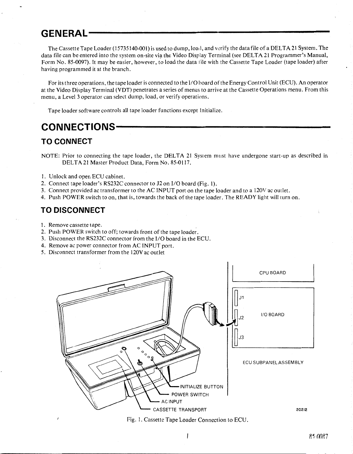
Unlock and open ECU cabinet.
2. Connect tape loader's RS232C connector to J2 on
3.
Connect provided ac transformer to the
4. Push POWER switch to on, that is, towards the back
21
Master Product Data, Form No. 85-0117.
AC
INPUT port on the tape loader and to a
TO DISCONNECT
21
System must have undergone start-up as described
I/O
board (Fig. l).
of
the tape loader. The READY light
of
a DELTA
21
Programmer's Manual,
120V
ac outlet.
will
turn on.
21
System. The
in
1.
Remove cassette tape. .
2.
Push POWER switch to off; towards front
3.
Disconnect the RS232C connector from the
4. Remove ac power connector from AC INPUT port.
5.
Disconnect transformer from the
120V
of
the tape loader.
1/0
ac outlet
board
in
the ECU.
INITIALIZE BUTTON
CPU BOARD
~J1
~J2
1/0 BOARD
~J3
ECU
SUBPANELASSEM BLY
CASSETTE TRANSPORT
Fig. I. Cassette Tape Loader Connection to ECU.
20212
RHlOR7
Page 3
OPERATIONS----------------------------------
l.
Place Cassette Tape (15735138-001) in the tape transport.
NOTE: To write-protect copies
2.
Press the INITIALIZE switch on the tape loader and wait for the tape to rewind.
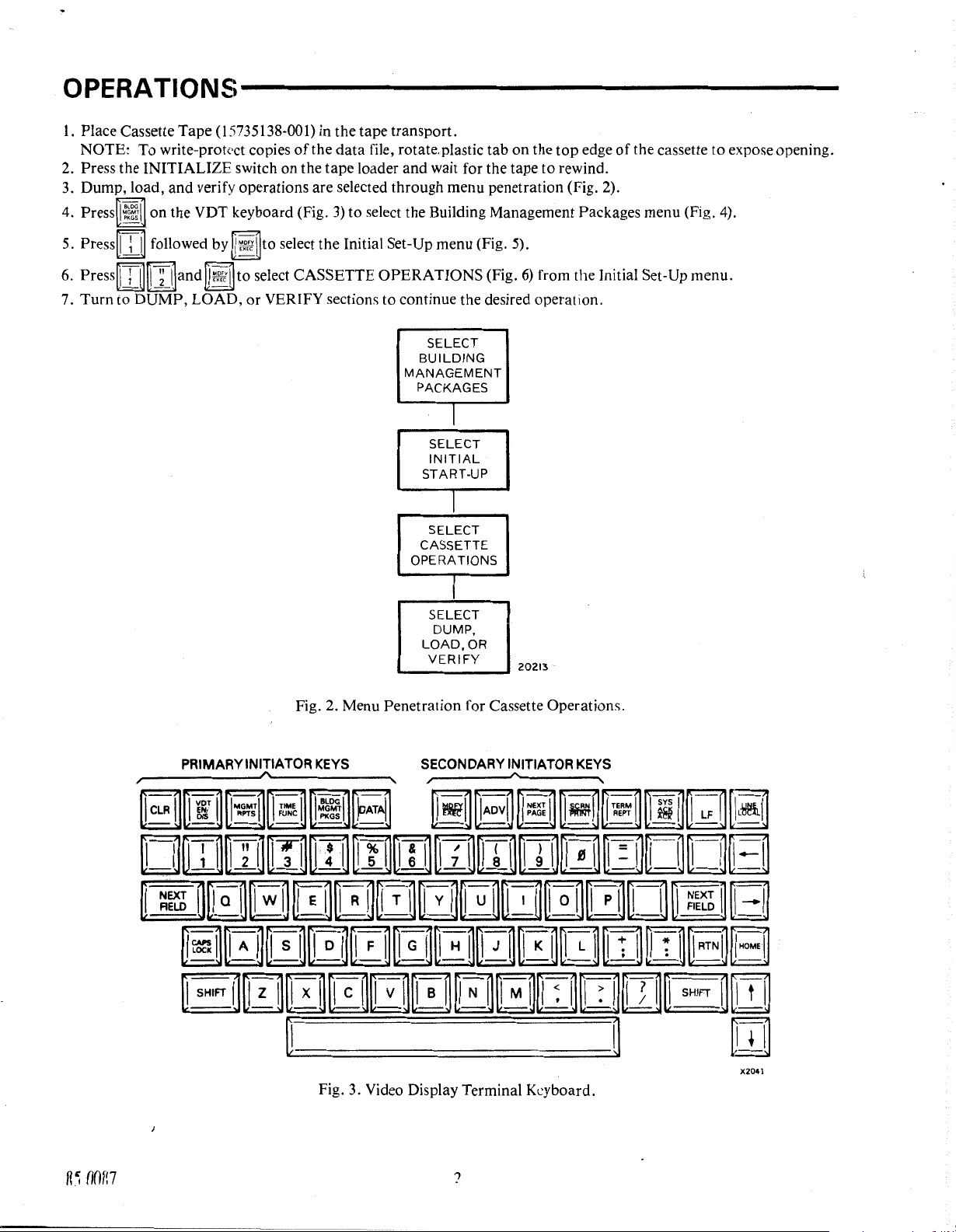
3. Dump, load, and verify operations are selected through menu penetration (Fig. 2).
4. Press on the VDT keyboard (Fig.
of
the data file, rotate.plastic tab on the top edge
3)
to
select the Building Management Packages menu (Fig. 4).
of
the cassette to expose opening.
Press~
5.
6.
Press~
7. Turn to DUMP, LOAD,
i
~followed
i @
~
by
!]and to select CASSETTE OPERATIONS (Fig.
to
select the Initial Set-Up menu (Fig. 5).
6)
from the Initial Set-Up menu.
or
VERIFY sections to continue the desired operation.
SELECT
BUILDING
MANAGEMENT
PACKAGES
I
SELECT
INITIAL
START-UP
I
SELECT
CASSETTE
OPERATIONS
I
SELECT
DUMP,
LOAD, OR
VERIFY
20213
PRIMARY
Fig. 2. Menu Penetration for Cassette Operations.
INITIATOR
KEYS
Fig. 3. Video Display Terminal Keyboard.
SECONDARY
INITIATOR
KEYS
X204l
Page 4
7
II
-----------------------------------------------------------
INITIAL
1.
OPTIMUM
2.
TIMED
3.
DUTY
4.
DEMAND
5.
OUTSIDE
6.
If
-----------------------------------------------------------
INITIAL
OUTSIDE
1.
PRINT
2.
DESIGN
3,
CHANGEOVER
4,
COMFORT
5.
ME
TI
6,
SET-UP
START/STOP
START/STOP
CYCLE
CONTROL
AIR
SELECTION
4.
Fig.
UP
SET
FUNCTION
TEMP-WINTER/SUMMER
HOUR
PT#/RH
TEMP
LIMITS-GLOBAL
ENABLE/DISABLE
TEMP-WINTER/SUMMER
FORMAT
7
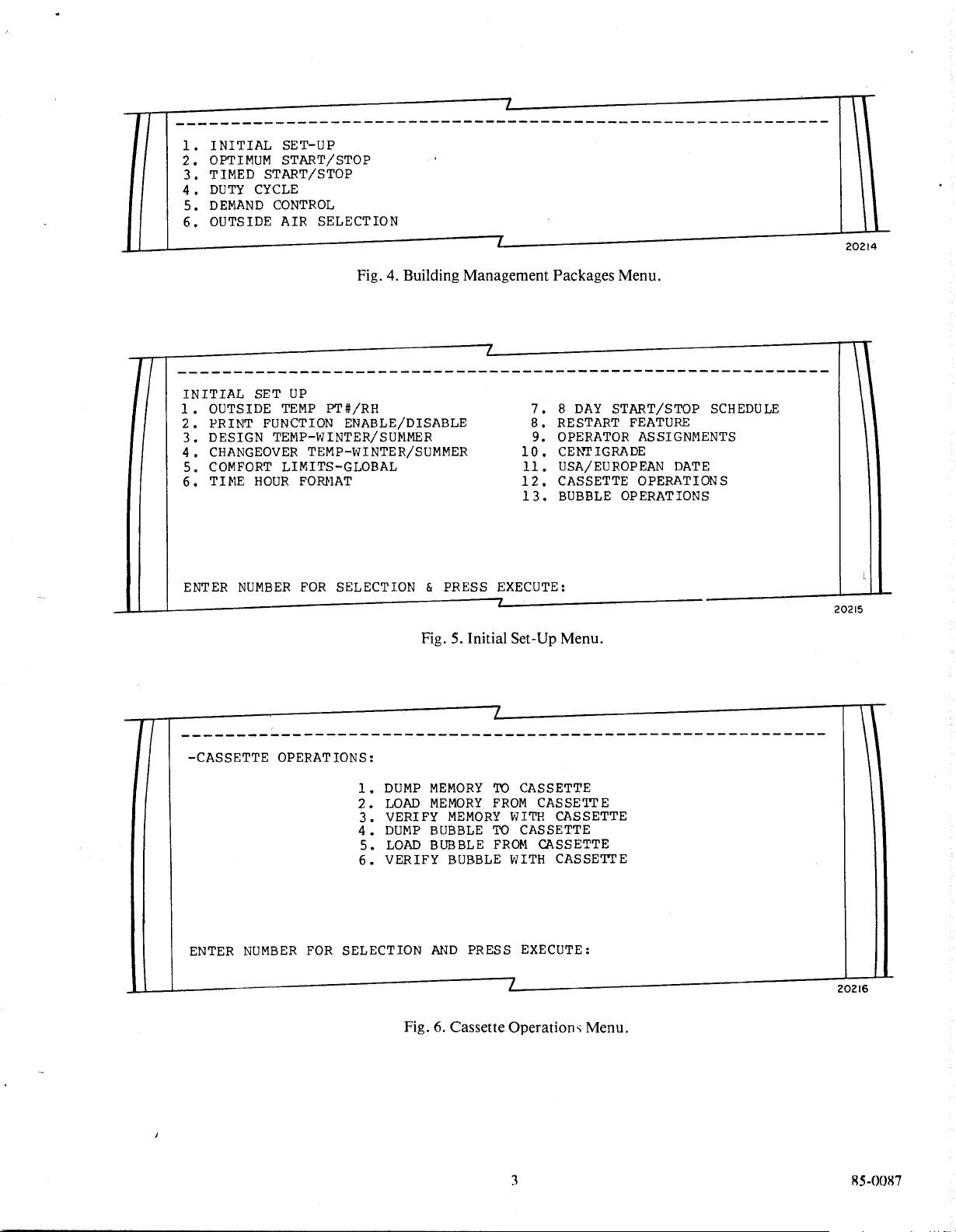
Building Management Packages Menu.
I
START/STOP
DAY
8
7,
RESTART
8,
OPERATOR
9,
CE:t-."TIGRADE
10,
USA/EUROPEAN
11,
CASSETTE
12,
BUBBLE
13.
FEATURE
ASSIGNMENTS
OPERATIONS
OPERATIONS
SCHEDULE
DATE
11
I
20214
ENTER
NUMBER
FOR
SELECTION
& PRESS
Fig. 5. Initial
I
I
----------------------------------------------------------
-CASSETTE OPERATIONS:
MEMORY
DUMP
ENTER
NUMBER
FOR
1,
2.
3.
4.
5.
6.
SELECTION
LOAD
VERIFY
DUMP
LOAD
VERIFY
Fig.
MEMORY
MEMORY
BUBBLE
BUBBLE
BUBBLE
AND
Cassette
6.
EXECUTE:
Set-Up Menu.
I
CASSETTE
TO
CASSETTE
FROM
TO
FROM
PRESS
Operation~
CASSETTE
WITH
CASSETTE
CASSETTE
CASSETTE
WITH
EXECUTE:
I
Menu.
20215
20216
85-0087
Page 5

DUMP
Press either
ENTER
TAPE
~ i ~
or
~ : ~followed
HEADER
(UP
press~~~.
-
If
either **ERROR -
heading and press I
-
If
CASSETTE
INPUT
~~~I
.
OPERATION
powered.
-
If
this
is
the first cassette operation, there will be a 92-second wait for the DELTA
Any Primary Initiator
Key
The display in Figure 7 indicates
DATA
software will attempt
and READY lights are flickering
to
recover from them.
I I
-CASSETTE OPERATION:
SIDE:
THIS
1
IS
THE
UP-TO
by
TO
79
CHARACTERS) & PRESS EXECUTE:
INCORRECT
FAILURE
(Fig.
3)
pressed at this time will be honored after the wait.
that
the
DUMP
79
COLUMN
~~.'.:"~to
and
select a
is
displayed, check cable connections and verify
ECU
data
the
FORWARD
TAPE
dump
operation from the
or
**ERROR - ILLEGAL KEY SEQUENCE
file
is
being dumped to
light
is
on
continuously.
I
HEADER
MESSAGE
Cassett~
is
displayed, enter a tape heading
the
cassette. The tape loader's RECEIVE
LINE.
Operations menu. When
is
displayed, reenter
that
the tape loader
21
System to become quiescent.
If
any errors occur, tape loader
and
is
ERRORS
PRESS
PRESS
&
**CASSETTE
**DATA
**BUBBLE
**WRITE
PLEASE
&
THIS
DISPLAYED
EXECUTE
CLEAR
FILE
FILE
ERROR
INSERT
PROMPT APPEARS
TO
TO
REWIND
ERROR
ERROR
NEW TAPE
ABORT
THIS LINE
CONTINUE~
FAILURE
SIDE
ONLY
IF
AN
.....--ili
ERROR
IS
DISPLAYED
ON
Fig. 7. Data File Being Dumped to Cassette.
85-0087 4
ON
THE
LINE
ABOVE
IT.
20217
Page 6

-
If
an unrecoverable error occurs:
Either
I
~~:zl
or~
cLR
ij
returns control
Any PIK (Primary Initiator
-
If
no error
The~cLR
Any PIK except
-
If
prompt PLEASE INSERT NEW
Turn tape over or insert a new tape, press INITIALIZE switch
dump operation.
The~
Any PIK
-
If
the
Either~
or
a recoverable error occurs:
ijaborts the dump operation and returns control to the Cassette Operations menu.
~cLR
~aborts
cLR
ij
aborts the dump operation and returns control to the Cassette Operations menu.
except~
dump
~ij or~
cLR
ij
aborts the dump operation, leaves cassette operations, and goes to the selected menu.
operation
cLR
is
successful, the display in Fig. 8 appears.
ijreturns control to the Cassette Operations menu.
to
the Cassette Operations menu.
Key)
except~
the dump operation, leaves cassette operations, and goes to the selected menu.
TAPE
cLR
ij1eaves
SIDE occurs:
cassette operations and goes to the selected menu.
on
the tape loader, and press
~-::;ijto
continue the
Any PIK
except~
CASSETTE OPERATION
PRESS
PRESS
cLR
~leaves
EXECUTE
CLEAR
TO
TO
ABORT
cassette operations and goes to the selected menu.
/
COMPLETE
CONTINUE
&
~
& SINCE
LOAD
NOTE: During load operation, the last tape side loaded must be the last side that was dumped.
Press
either~
THE
OPERATION
~
~or~
~
1]
IS
COMPLETE
followed by
THIS
MESSAGE
Fig.
8.
Completed Dump Operation.
l'ffiiJ
to select a load operation from the Cassette Operations menu.
IS
NO
LONGER
VALID.
~
20218
-
If
either **ERROR -
heading and press
-
If
CASSETTE
powered.
-
If
this is the first cassette operation, there
Any Primary Initiator
The display in Figure 9 indicates that the contents
The TRANSMIT DATA and READY lights are flickering and the FORWARD light
INPUT
J~~:,'J
.
OPERATION
Key
(Fig.
INCORRECT or **ERROR - ILLEGAL
FAILURE
3)
is
displayed, check cable connections and verify that the tape loader
will
be a 92-second wait for the DEL
pressed at this time will be honored after the wait.
of
the cassette are being loaded into either RAM or bubble memory.
KEY
s
SEQUENCE
TA
21
System to become quiescent.
is
on
continuously.
is
displayed, reenter
is
85-0087
Page 7

I
I
I
-CASSETTE OPERATION:
&
**CASSETTE
**DATA
**BUBBLE
**FATAL
**THIS
PLEASE
SIDE:
THIS
ERRORS
PRESS
PRESS
1
IS
THE
DISPLAYED
EXECUTE
CLEAR
REWIND
FILE
ERROR
FILE
READ
DUMP
WAS
INSERT
UP-TO 7 9
TO
TO
ABORT
FAILURE
ERROR
ERROR
ABORTED
NEW
TAPE
LOAD
COLUMN
ON
THIS
CONTINUE~
SIDE
HEADER
LINE~
MESSAGE
LINE.
&
THIS
PROMPT
Error
messages may also be printed
TION
ERROR, and BAD
errors.
-
If
an
unrecoverable error occurs:
Either I
Any
-
If
The~
Any
-
If
~f£1
PIK
except
no error
cLR
ij
aborts
PIK
except~
prompt
or~
cLR
~returns
~cLR
or
a recoverable error occurs:
t~load
cLR
PLEASE
Insert new tape side, press
The
~cLR
ijaborts
Any
PIK
-
If
the load operation
Either~~~
t~load
except~cLR
or
~cLR
~returns
APPEARS
TAPE
~leaves
ONLY
IF
AN
ERROR
Fig. 9. Loading RAM
on
the SARA
IS
DISPLAYED
11
Printer. These are, READ
ON
THE
or
Bubble Memory.
LINE
ABOVE.
ERROR
20219
ENCOUNTERED, INSER-
FILE ENCOUNTERED. Tape loader software will attempt to recover from these
control
operation
to
the Cassette Operations menu.
cassette operations and goes
and
returns control
to
the selected menu.
to
the Cassette Operations menu.
ijaborts the load operation, leaves cassette operations, and goes to the selected menu.
INSERT
~aborts
is
NEWT
INITIALIZE
operation
APE
SIDE occurs:
switch
on
the tape loader, and
and
returns control to the Cassette Operations menu.
press~~~
to continue the load operation.
the load operation, leaves cassette operations, and goes to the selected menu.
successful, the display in Fig.
control
to
the Cassette Operations menu.
10
appears.
R5
OOR7
Any p
IK
except~
CLR
~leaves
cassette operations and goes to the selected menu.
(,
Page 8

**READ
CASSETTE
PRESS
ERRORS
EXECUTE
ENCOUNTERED
OPERATION
TO
CONTINUE
COMPLETE
&
PRESS
&
THIS
& SINCE
CLEAR
MESSAGE
THE
OPERATION
VERIFY
NOTE:
Be
sure tapes are inserted
Press either
-
If
selection and
-
If
powered.
-
If
Any Primary Initiator Key (Fig
~'f~
or~
either **ERROR -
press~~~.
CASSETTE OPERATION FAILURE
this
is
thf
first cassette operation, there will be a 92-second wait for the DELTA
'IO
ABORT
IS
DISPLAYED
~
~followed
INPUT
&
ONLY
IF
IS
COMPLETE
Fig.
in
the tape transport in the order that the
by
~!fmUto
INCORRECT
3)
pressed at this time will
THIS
10.
Completed Load Operation.
select a verify operation from the Cassette Operations menu.
is
displayed, check cable connections and verify that the tape loader
RECOVERABLE
MESSAGE
or
**ERROR - ILLEGAL
READ
IS
NO
be
honored after the wait.
ERRORS OCCURED.
LONGER
\
data
KEY
VALID.
file
was
SEQUENCE
20220
dumped.
is
displayed, reenter
21
System to become quiescent.
is
The display in Figure
of
the cassette. The TRANSMIT DATA, RECEIVE DATA, and READY lights are flickering and the FORWARD light
on
continuously. ,
is
Some error messages may be printed on the SARA
FILE ENCOUNTERED. Tape loader software
-
If
an unrecoverable error occurs:
Either
~3
Any
PIK
except~cLR
-
If
no error or a recoverable error occurs:
The~
cLR
ij
aborts the load operation and returns control to the Cassette Operations menu.
Any
PIK
except~cLR
-
If
either PLEASE INSERT
Insert new (or correct) tape side, press INITIALIZE switch on the tape loader, and then press
verify operation.
The~
eu1
ij
aborts
PIK
Any
-
If
the verify ?peration
sette Operations menu.
Any
except~eu1
PIK
except~cLR
11
indicates that the
or~
cLR
ij
returns control to the Cassette Operations menu.
ij
leaves cassette operations and goes to the selected menu.
ijaborts the load operation, leaves cassette operations, and goes
t~
verify operation and returns control to the Cassette Operations menu.
ijaborts the verify operation, leaves cassette operations, and goes to the selected menu.
is
ij1eaves
data
file in RAM
11
will
attempt to recover from these errors.
NEWT
successful, the display in Figure
cassette operations and goes to the selected menu.
APE
SIDE
or
or
bubble memory
Printer; READ ERROR ENCOUNTERED and BAD
WRONG SIDE. PLEASE INSERT SIDE nn
12
appears.
Either~
is
now being verified with the contents
to
the selected menu.
is
displayed:
~'l'Wl~to
~ijor~cLR
ijreturns control
continue the
to
the Cas-
TAPE
7
R.~-OOR7
Page 9

I I
I
I
-CASSETTE
OPERATION:
VERIFY
SIDE: 1
THIS IS
ERRORS
PRESS
PRESS
UP-TO
THE
DISPLAYED
EXECUTE
CLEAR
TO
COLUMN
79
THIS
ON
CONINUE~
TO
ABORT
TAPE
LINE---
HEADER
/::...
~
MESSAGE
LINE.
~::::::::====------~~----::::::::::::::::::
ERROR
EMPTY
ERROR
TAPE SIDE
NEW
FAILURE
ONLY
**CASSETTE REWIND
&
**DATA
**DATA
**BU3BLE
**BUBBLE
**FATAL
PLEASE INSERT
**WRONG SIDE. PLEASE INSERT SIDE
THIS PROMPT
&
EMPTY
FILE
ERROR
FILE
FILE
FILE
READ
APP~ARS
Fig.
**READ
ERRORS
CASSETTE
PRESS
PRESS
EXECUTE
CLEAR
ENCOUNTERED
OPERATION
CONTINUE
TO
ABORT
TO
COMPLETE
AN
IF
Verification
11.
&
nn
ERROR
THE
DISPLAYED
IS
Cassette with Memory.
of
TAPE
ON
VERIFIED
LINE
AND
ABOVE
VALID
IT.
20221
&
&
&
85-0087
MESSAGE
THIS
MISMATCHES OCCURED
IF
VERIFICATION
"TAPE
IS DISPLAYED
ONLY
DURING
ERROR".
rig.
RECOVERABLE READ ERRORS OCCURED.
IF
READ
WILL
LINE
Verify
8
THIS
Operation.
VERIFICATION,
Completed
12.
20222
Page 10

PRINTER MESSAGES
**BUBBLE FILE
of
record
CASSETTE OPERATION
**CASSETTE OPERATION
ERROR-The
Bubble File Manager indicated that an error occurred when trying to access the next
information. This error
COMPLETE-The
FAILURE-
is
unrecoverable.
specified operation
is
completed.
The specified operation could not be started. This error
may not be powered or connected correctly.
**CASSETTE REWIND
FAILURE-The
tape loader did not respond to a command
with an error. The tape loader may not be connected correctly or there may not
**DAT A FILE
**DAT A FILE
access the next record
**ERROR
have been read or a character may
EMPTY-The
ERROR-The
INT
APE
verify operation was selected when there
Data File Manager (RAM manager) indicated that an error occurred when trying
of
information. This error
FORMAT-While
be
is
nothing
is
unrecoverable.
reading the tape, the format did not seem right.
missing. Tape loader software
will
again.
**FAT
ALT
APE READ
ERROR-An
unrecoverable error occurred while reading the tape. The tape loader might not
be connected correctly or the tape may be damaged.
**INSERTION
ERROR-The
tape loader software attempted to insert the record
Data File Manager (RAM manager)
it
loaded
off
or
Bubble File Manager indicated an error when
the tape. Loading
record from the tape.
is
fatal. Tape loader
to
rewind the tape or it responded
be
any tape in it.
in
the data file.
to
An
extraneous character may
skip to a point in the tape where it can try
will
continue
by
reading the next
**INVALID FILE TYPE
ENCOUNTERED-An
invalid data file type
was
read from the tape. This indicates a bad
tape; possibly worn out or damaged.
SIDE:n
THIS
IS A TAPE
header was entered by the operator when the tape
**TAPE READ
sum. The record
TAPE
VERIFICATION
match the content
TAPE
VERIFIED AND V
the contents
**TAPE WRITE
nected correctly or the cassette may not be
**THIS DUMP WAS
HEADER
ERROR-A
will
be
....
-During
recoverable error occurred when reading the tape. A record
skipped, and the next record sought.
ERROR-After
of
the (RAM or bubble) memory.
AUD-After
of
the (RAM or bubble) memory.
ERROR-An
unrecoverable error occurred when writing to the tape. The tape loader may not
ABORTED-The
a verify operation, the results indicated that the contents
tape being loaded or verified was not a completed dump
an operation the side number and tape header are displayed. The tape
was
dumped.
a verify operation, the results indicated that the contents
in
the tape transport.
ble) memory because the operator aborted the dump operation. When loading, the data files
cleared.
was
read with a bad check-
of
the tape did not
of
the tape matched
of
the (RAM or bub-
in
RAM and bubble
be
will
con-
be
<)
RS-0087
Page 11

FILE: KEY: MISSING
TAPE
RECORD-When
by FILE and KEY, but the tape did not. The next record
KEY:
FILE:
__
data file did not. The next record
MISSING DATA FILE
will
be sought.
RECORD-When
will
be sought.
verifying, the data
file
contained the record specified
verifying, the tape contained a record that the
FILE: KEY:
the tape
FILE:
as
___
it
is
in the data file. The next record
KEY:
LOADING FILE:
___
___
**MISMATCH-When
MATCH-When
KEY:
__
-The
verifying, the content
will
be sought.
of
the specified record
was
verifying, the specified record on the tape matched that
specified record
is
being loaded from the tape to the (RAM or bubble)
not the same on
of
the data file.
memory.
DUMPING FILE:
___
KEY:
__
-The
specified record
is
being dumped from (RAM or bubble) memory to the
tape.
**READ ERRORS
ENCOUNTERED-This
is
a reminder, after a load or verify, that recoverable read errors were
encountered.
MAINTENANCE-----------------------------
The Cassette Tape Loader requires little maintenance. The head should be cleaned with isopropyl alchohol using a
lint free cotton swab as needed.
becomes questionable, cleaning the head or changing the tape solves the problem.
If
the tape loader
will
rewound prior to being removed from the transport and they should be stored rewound.
If
the unit
not
be
used for more than an hour, the tape should be rewound. Tape cassettes should be
~------CAUTION--------
is
used every day, the heads should be cleaned once a week. Normally,
if
data
85-0087
Commercial
Mlr
T/\n:
IV. M.
Bldg
r,
Group
Never add lubrication to shafts or bearings.
Honeywell
ln
the
USA:
Honeywell
In
Subsidiaries
Canada:
and
Plaza,
Minneapolis,
Scarborough,
Afflllates
Printed
tn
Around
U!>A
Minnesota
Ontario
the
World
55408
10-83
 Loading...