

Page 1
Pressure switches
Mechanical pressure switches
Mechanical pressure switches
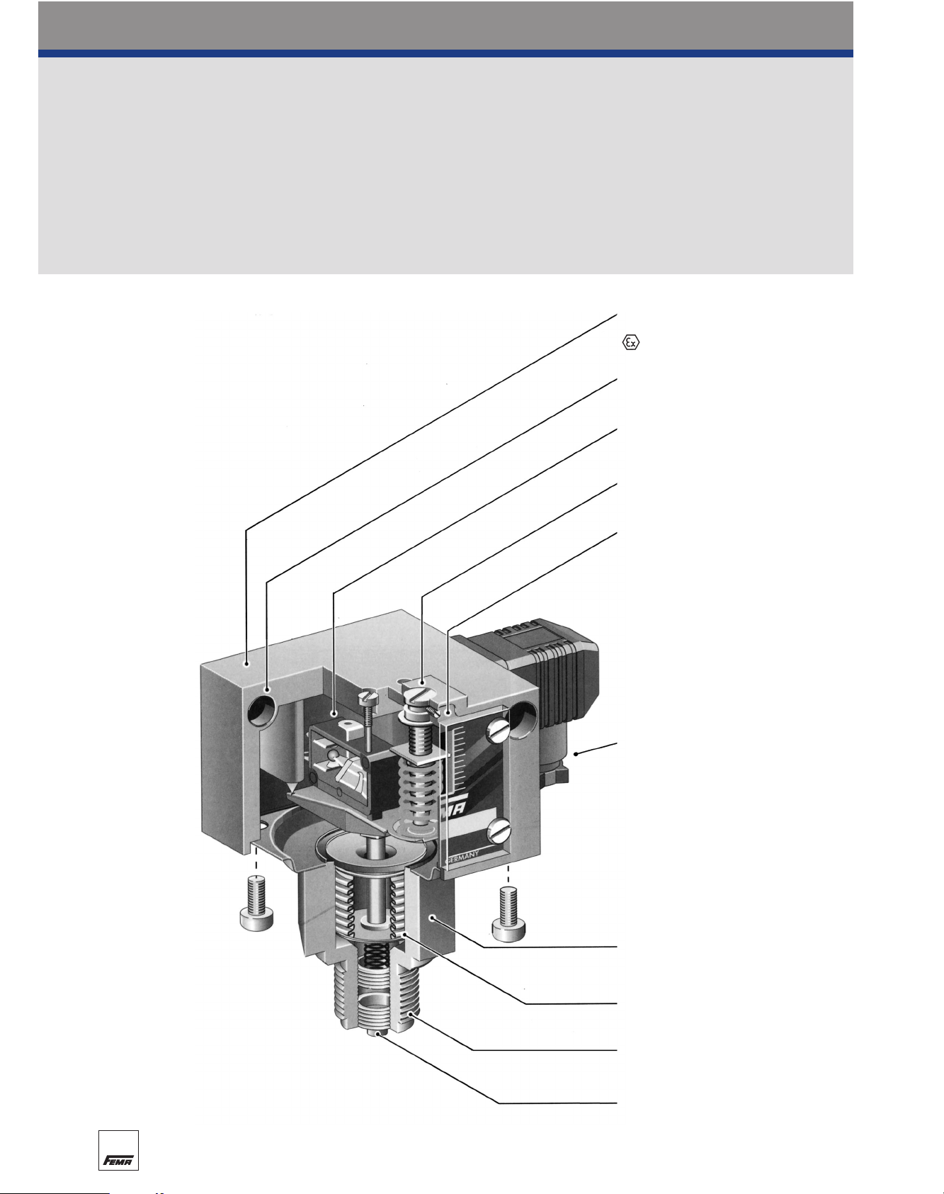
Technical features / Advantages
Wall mounting
or directly on the pressure line
Switching element (microswitch)
Lead sealable setpoint adjustment
Setting spindle locking element
Terminal connection
or plug connection to
DIN 43 650 Form A
Stainless steel sensor housing
Stainless steel bellows
with internal stop
Pressure connection
G 1/2“ external
G 1/4” internal
Centring pin
18
Diecast aluminium housing
IP 54 or IP 65
version also available
Page 2
Pressure switches
Mechanical pressure switches
Pressure switches
General description
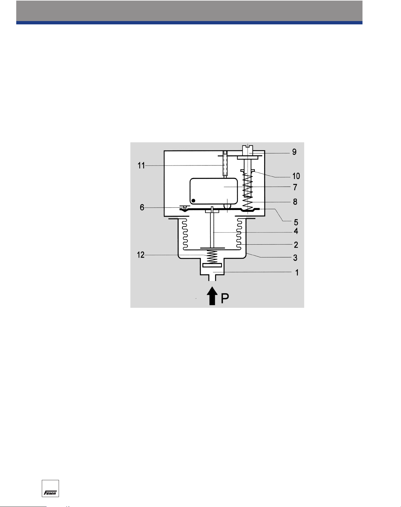
Operating mode
The pressure occurring in the sensor housing (1) acts on the measuring bellows (2). Changes in pressure lead to movements of the measuring bellows (2) which are transmitted via a thrust pin (4) to the
connecting bridge (5). The connecting bridge is frictionlessly mounted on hardened points (6). When the
pressure rises the connecting bridge (5) moves upwards and operates the microswitch (7). A counterforce is provided by the spring (8) whose pretension can be modified by the adjusting screw (9)
(switching point adjustment). Turning the setting spindle (9) moves the running nut (10) and modifies
the pretension of the spring (8). The screw (11) is used to calibrate the microswitch in the factory. The
counter-pressure spring (12) ensures stable switching behaviour, even at low setting values.
Pressure sensors
Apart from a few exceptions in the low-pressure range, all pressure sensors have measuring bellows,
some made of copper alloy, but the majority of high-quality stainless steel. Measured on the basis of
permitted values, the measuring bellows are exposed to a minimal load and perform only a small lifting
movement. This results in a long service life with little switching point drift and high operating reliability.
Furthermore, the stroke of the bellows is limited by an internal stop so that the forces resulting from
the overpressure cannot be transmitted to the switching device. The parts of the sensor in contact
with the medium are welded together without filler metals. The sensors contain no seals. Copper bellows, which are used only for low pressure ranges, are soldered to the sensor housing. The sensor
housing and all parts of the sensor in contact with the medium can also be made entirely from stainless steel 1.4571 (DNS series). Precise material data can be found in the individual data sheets.
Pressure connection
The pressure connection on all pressure switches is executed in accordance with DIN 16288 (pressure
gauge connection G 1/2A). If desired, the connection can also be made with a G 1/4 internal thread
according to ISO 228 Part 1. Maximum screw-in depth on the G 1/4 internal thread = 9 mm.
Centring pin
In the case of connection to the G 1/2 external thread with seal in the thread (i.e. without the usual
sheet gasket on the pressure gauge connection), the accompanying centring pin is not needed.
Differential pressure switches have 2 pressure connections (max. and min.) each of which are connected to a G 1/4 internal thread.
1 = Pressure connection
2 = Measuring bellows
3 = Sensor housing
4 = Thrust pin
5 = Connecting bridge
6 = Pivot points
7 = Microswitch or other switch-
ing elements
8 = Setting spring
9 = Setting spindle (switching
point adjustment)
10 = Running nut (switching point
indicator)
11 = Microswitch calibration
screw (factory calibration)
12 = Counter pressure spring
26
Page 3
General technical data
Diecast aluminium GD AI Si 12 Diecast aluminium GD AI Si 12
G 1/2 external thread (pressure gauge connection) and G 1/4 internal thread
G 1/4 internal thread for DDCM differential pressure switches
Floating changeover contact. Floating changeover contact.
With rising pressure switching With rising pressure switching
single-pole from 3-1 to 3-2. single-pole from 3-1 to 3-2.
8 A at 250 VAC 3 A at 250 VAC
5 A at 250 VAC inductive 2 A at 250 VAC inductive
8 A at 24 VDC 3 A at 24 VDC
0.3 A at 250 VDC 0.03 A at 250 VDC
min. 10 mA, 12 VDC min. 2 mA, 24 V DC
preferably vertical vertical
(see technical data sheet)
IP 54; (for terminal connection …300 IP 65) IP 65
– EEx de IIC T6 tested to EN
50014/50018/50019 (CENELEC)
– PTB 02 ATEX 1121
Plug connection to DIN 43 650 (200 series) Terminal connection
or terminal connection (300 series)
PG 11 / for terminal connection M 16 x 1.5 M 16 x 1.5
See data sheets –15 to +60°C
Adjustable via spindle. On switching device Adjustable via spindle after the
300 the terminal box cover must be removed terminal box lid is removed
Adjustable or not adjustable Not adjustable
(see Product Summary)
Only possible on plug connection housing 200
Max. 70°C, briefly 85°C Max. 60°C
Higher medium temperatures are possible provided the above limits for the switching device are
ensured by suitable measures (e.g. siphon).
All pressure switches can operate under vacuum. This will not damage the device.
< 1% of the working range (for pressure ranges > 1 bar)
No significant deviations up to 4 g.
With sinusoidal pressure application and room temperature, 10 x 106 switching cycles.
The expected life depends to a very large extent on the type of pressure application, therefore this figure can serve only as a rough estimate. With pulsating pressure or pressure impacts in hydraulic systems, pressure surge reduction is recommended.
Overvoltage category III, contamination class 3, reference surge voltage 4000 V.
Conformity to DIN VDE 0110 (01.89) is confirmed.
The parts of all pressure switches with sensors made from steel or stainless steel are oil and greasefree. The sensors are hermetically encapsulated. They contain no seals. (See also additional function
ZF 1979 Special Packing)
Switch housing
Pressure connection
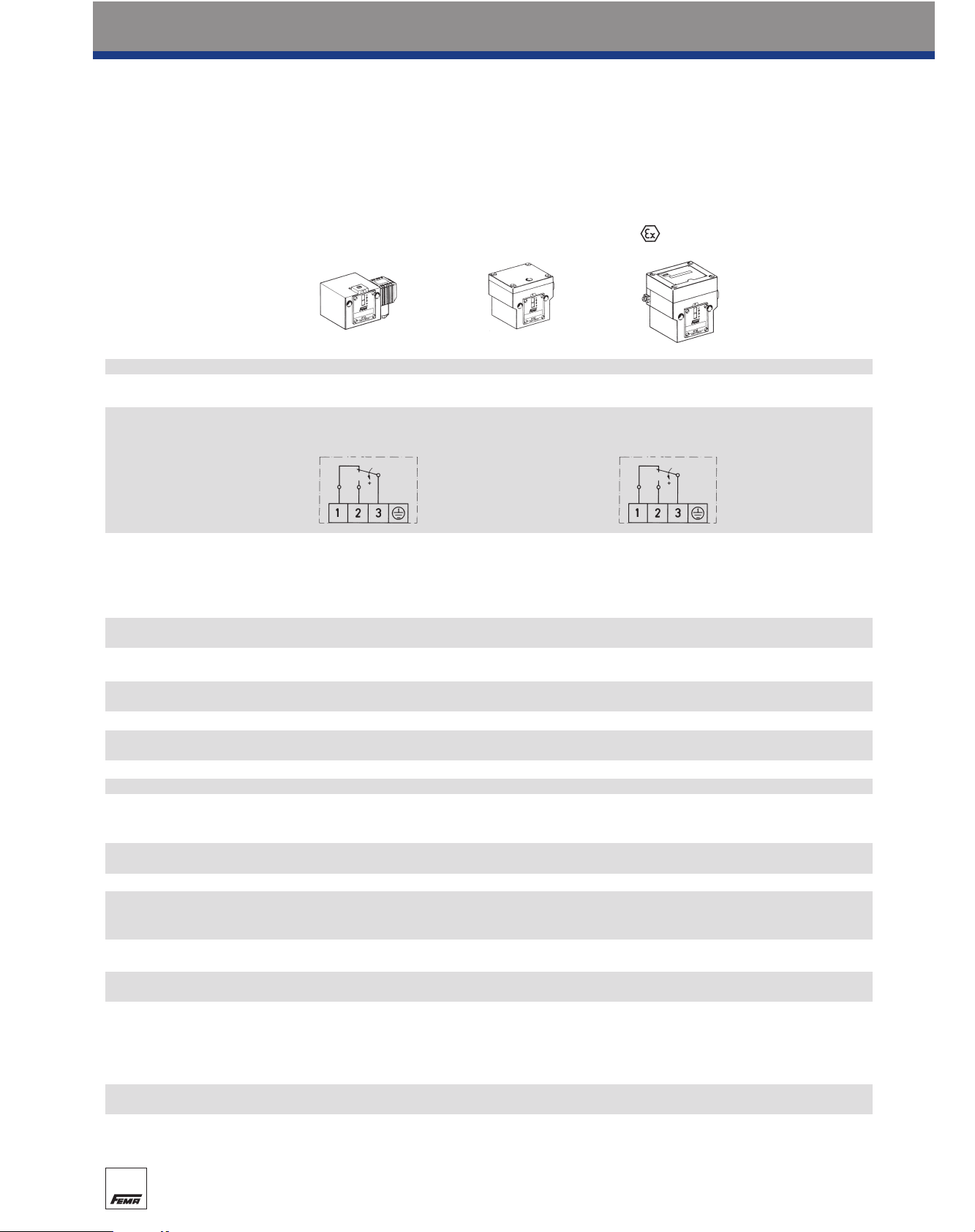
Switching function and connection diagram
(applies only to version with
microswitch)
Switching capacity
(applies only to version with
microswitch)
Mounting position
Degree of protection (in vertical
position)
Ex degree of protection
PTB approval Electrical connection
Cable entry
Ambient temperature
Switching point
Switching differential
Lead seal
Medium temperature
Vacuum
Repetition accuracy of switching points
Vibration strength
Mechanical life
Isolation values
Oil and grease-free
Normal version
Plug connection Terminal connection
…200 …300
version
…700
with microswitches of the DCM, VCM, DNM, DNS and DDC series.
The technical data of type-tested units may differ slightly.
(please refer to type sheet)
Pressure switches
Mechanical pressure switches
27
Page 4

Pressure switches
Mechanical pressure switches
General information about
explosion protection
Basic principle
The basic principle of explosion protection is that:
a) combustible materials (gas, vapour, mist or dust) in dangerous quantities
b) air (or oxygen)
c) ignition sources
must not occur in the same place.
The permanent or temporary occurrence of explosive mixtures as per a) and b) is often unavoidable,
therefore when operating electrical installations care must be taken to ensure that no ignition sources
can occur.
With this in mind, the CENELEC technical committee has adopted the following European standards
which are recognized in all EU member states.
· General requirements EN 50 014 · Pressure resistant encapsulation “d” EN 50 018
· Oil encapsulation “o” EN 50 015 · Increased safety “e” EN 50 019
· Overpressure encapsulation “p” EN 50 016 · Intrinsic safety “i” EN 50 020
· Sand encapsulation “q” EN 50 017 · Cast encapsulation “m” EN 50 028
The guidelines relevant to FEMA products – besides the “General Requirements EN 50 014” – are
“Pressure resistant encapsulation d” and “Intrinsic safety i”.
In addition, all explosion protection guidelines issued up to the present time have been combined into
a single European Ex-Protection Directive 94/9EC. The aim of this new harmonized directive is to bring
the explosion protection regulations of European member states into line with one another and eliminate barriers to trade between partner states. The new Directive 94/9EC (ATEX 100a), which came
into force on 1 July 2003, replaces all previous directives.
All FEMA ex-pressure switches and ex-thermostats meet the requirements of the new European ExProtection Directive 94/9EC (ATEX 100a).
Pressure resistant encapsulation “d”
Switching elements and other electrical function units capable of igniting an explosive mixture are cast
in a housing capable of withstanding the explosive pressure caused by an explosion indoors and preventing transmission to the surrounding atmosphere.
Intrinsic safety “i”
The equipment used in the area at risk of explosion contains only intrinsically safe electric circuits. An
electric circuit is only intrinsically safe if the quantity of energy is so small that no spark or thermal
effect can occur.
The term “simple electrical equipment”
In view of the use of simple microswitches without additional capacitance or inductance generating
components, our pressure switches and thermostats designed for protection type Ex-i fall in the category of “simple electrical equipment”. These are not subject to testing or certification requirements
within the meaning of Directive 94/9EC. The units may only be used in conjunction with ATEX-tested
isolating amplifiers in areas at risk of explosion. We equip all units which are explicitly designed for
such use with microswitches having gold contacts, a grounding screw and — for ease of identification
— a blue cable entry.
EEx-d
EEx-i
21
Page 5

Pressure switches
Mechanical pressure switches
General information about
explosion protection
Zone classification
Explosion risk areas are grouped into zones according to the likelihood of a dangerous explosive
atmosphere according to EN 1127-1 occurring.
When assessing the explosion hazard, i.e. when identifying explosion risk areas, the “Guidelines for
the Avoidance of Danger due to Explosive Atmospheres with Examples (ExRL)” of the German
Insurance Association for the Chemical Industry [Berufsgenossenschaft Chemie] must be taken into
account.
If the situation concerns a special case or if doubts exist as to the definition of explosion risk areas, the
matter shall be decided by the supervisory authorities (Trade Supervisory Office [Gewerbeaufsichtsamt], where applicable with the assistance of the Insurance Association or the Technical Control
Boards [Technische Überwachungsvereine]).
In Zones 0 (20) and 1 (21), only electrical equipment for which a type test certificate has been issued
by a recognized testing agency may be used. In Zone 0 (20), however, only equipment expressly
authorized for that zone may be used. Equipment approved for use in Zones 0 (20) and 1 (21) may
also be used in Zone 2 (22). Under the new European Directive 94/9 EC (ATEX 100a), a distinction is
made between gas atmospheres and dust atmospheres. This results in the following zone classifi-
cations:
Zone 0 Zone 0 (gas) is a place in which a dangerous explosive
atmosphere is present continuously or for long periods. This
normally includes only the interior of containers or the interior
of apparatus (evaporators, reaction vessels etc.), if the conditions of Zone 0 are fulfilled. Continuous danger > 1000
hours/year.
Zone 1 occasionally Zone 1 (gas) is a place in which a dangerous explosive
atmosphere can be expected to occur occasionally in normal
operation. This may include the immediate vicinity of Zone 0.
Occasional danger = 10 to 1000 hours/year.
Zone 2 Zone 2 (gas) is a place in which a dangerous explosive
atmosphere can be expected to occur only rarely and then
only for short periods. This may include areas surrounding
Zones 0 and/or 1. Danger only under abnormal operating conditions < 10 hours/year.
Zone 20 Zone 20 (dust) is a place in which a dangerous explosive
atmosphere in the form of a cloud of dust in air is present
continuously or for long periods, and in which dust deposits of
unknown or excessive thickness may be formed. Dust
deposits on their own do not form a Zone 20. Continuous
danger > 1000 hours/year.
Zone 21 occasionally Zone 21 (dust) is a place in which a dangerous explosive
atmosphere in the form of a cloud of dust in air may occasionally occur in normal operation, and in which deposits or layers
of inflammable dust may generally be present. This may also
include the immediate vicinity of Zone 20. Occasional danger
= 10 to 1000 hours/year.
Zone 22 Zone 22 (dust ) is a place in which a dangerous explosive
atmosphere may be expected to occur only rarely and then
only for short periods. This may include areas in the vicinity of
Zones 20 and 21. Danger only under abnormal operating conditions < 10 hours/year.
GasDust
22
continuously or
for long periods
seldom and for
short periods
continuously or
for long periods
seldom and for
short periods
Page 6

General information about
explosion protection
Temperature class Ignition temperature °C Maximum surface temperature
°C
T1 > 450 450
T2 > 300 300
T3 > 200 200
T4 > 135 135
T5 > 100 100
T6 > 85 85
Explosion group
The requirements for explosion-protected equipment depend on the gases and/or vapours present on
the equipment and on the dusts lying on, adhering to and/or surrounding the equipment. This affects
the gap dimensions required for pressure-proof encapsulation and, in the case of intrinsically safe circuits, the maximum permitted current and voltage values. Gases, vapours and dusts are therefore
subdivided into various explosion groups.
The danger of the gases rises from explosion group IIA to IIC. The requirements for electrical equipment in these explosion groups increase accordingly. Electrical equipment approved for IIC may also
be used for all other explosion groups.
Temperature class
The maximum surface temperature of an item of equipment must always be lower than the ignition
temperature of the gas, vapour or dust mixture. The temperature class is therefore a measure of the
maximum surface temperature of an item of equipment.
Pressure switches
Mechanical pressure switches
Identification of explosion-protected electrical equipment
In addition to normal data (manufacturer, type, serial number, electrical data), data relating to the explosion protection must be included in the identification.
Under the new Directive 94/9EC (ATEX 95), based on IEC recommendations, the following identification is required:
For example: II G D EEx de IIC T6 IP65 T 80 °C
Ex-protection symbol
Device group II
Approved for gas
Approved for dust
Symbol for equipment built in
accordance with European standards
Explosion protection identifier
Explosion group
Temperature class
IP protection class
Approved maximum temperature
23
Page 7

Pressure switches
Mechanical pressure switches
Specially equipped pressure switches can also be used in explosion risk areas Zone 1, 2 and 21,
22. The following alternatives are possible:
1. Pressure-proof encapsulated switching device,
explosion protection EEx de IIC T6, PTB 02 ATEX 1121
The pressure switch with pressure-proof encapsulation can be used directly in the explosion risk area
(Zone 1 and 2 or 21 and 22). The maximum switching voltage, switching capacity and ambient temperature must be taken into account and the rules for installation in the explosion risk area must be
observed. All pressure switches may be equipped with explosion-proof switching devices. However,
special circuits and designs with an adjustable switching differential or internal interlock (reclosing lockout) are not permitted.
2. EEx-i pressure switches
All pressure switches of normal design can be used in explosion risk areas Zone 1 and 2 or 21 and
22, if they are integrated into an “intrinsically safe control current circuit”. Intrinsic safety is based on
the principle that the control current circuit in the explosion risk area carries only a small quantity of
energy which is not capable of generating an ignitable spark.
Isolating amplifiers, e.g. type Ex 011 or Ex 041, must be tested by the Physikalisch-Technische
Bundesanstalt (PTB) and approved for use in explosion risk areas. Isolating amplifiers must always be
installed outside the explosion risk zone.
Pressure switches designed for EEx-ia installations may be provided with blue connection terminals
and cable entries. In view of the low voltages and currents carried via the contacts of the microswitches, gold-plates contacts are recommended (additional function ZF 513).
3. Pressure switches with microswitch and resistor combination for short-circuit and line
break monitoring (see DBS series)
A combination of a pressure switch with mechanical microswitch connected to a 1.5 kOhm series
resistor and a safety-engineered isolating amplifier (type Ex 041) may also be used in explosion risk
zones 1, 2 and 21, 22 (explosion protection EEx-ia).
The safety-engineered isolating amplifier produces a separate intrinsically safe control current circuit
and at the same time monitors the supply conductors between the isolating amplifier and the pressure
switch for short-circuit and line break. In this regard, see also the section on pressure limiters for safety-critical applications and data sheet Ex 041.
Pressure monitoring in explosion risk
areas Zone 1, 2 and 21, 22
Ex-D…
Pressure-proof encapsulated
Explosion protection: EEx de
IIC T6 PTB approval for the
complete switching device.
Switching capacity at 250 V/3
A. The pressure switch can be
installed within the Ex-Zone.
D…-513 + Ex 011
Intrinsically safe
Explosion protection: EEx-ia
PTB approval for isolating
amplifiers Ex 041 Pressure
switch with gold-plated contacts, blue terminals and blue
cable entries.
The isolating amplifier must be
installed outside the Ex-Zone.
DWR…-576 + Ex 041
Intrinsically safe, line break
and short-circuit monitoring
Explosion protection: EEx-ia
PTB approval for isolating
amplifiers Ex 041 Pressure
switch with safety sensor,
positive opening microswitch,
gold-plated contacts, blue terminals and blue cable entries.
The isolating amplifier must be
installed outside the Ex-Zone.
Pressure monitoring in explosion risk areas Zone 1 (21) and 2 (22)
24
Page 8

DDCM 252
Degree of protection:
IP 54/65
s
FEMA differential pressure switches are suitable
for monitoring and controlling differential pressures, flow monitoring and automatic control of
filter systems. A double chamber system with
stainless steel bellows or Perbunan diaphragm
accurately detects the difference between the
two applied pressures. The desired switching
pressure is continuously adjustable within the
ranges mentioned in the type summary.
The settings relate to the lower switching point
(with falling differential pressure). The upper
switching point (with rising differential pressure)
is higher by the amount of the switching differential. All differential pressure monitors can also be
used in the vacuum range. Every pressure
switch has 2 pressure connections with appropriate markings.
DDCM type series
Differential pressure switch
Ex-DDCM
Technical data
Pressure connection
Internal thread G 1/4
Switching device
Robust housing (200) made of seawater-resistant diecast aluminium GD Al Si 12.
Degree of protection
IP 54, in vertical position.
IP 65, for EEx-d version.
Pressure sensor materials
DDCM 014–16:
Pressure bellows of 1.4571
Sensor housing of 1.4305.
DDCM 252–6002:
Perbunan diaphragm.
Aluminium sensor housing.
Mounting position
vertically upright.
Ambient temperature at switching device
–25…+70 °C
For EEx-d versions: –15…+60 °C
Max. medium temperature
The maximum medium temperature at the
pressure sensor must not exceed the permitted ambient temperature at the switching
device. Temperatures may reach 85°C for
short periods (not EEx-d). Higher medium temperatures are possible provided the above limit
values for the switching device are ensured by
suitable measures (e.g. siphon).
Mounting
Directly on the pressure line or on a flat surface with two 4 mm Ø screws.
Note the connection of pressurized lines:
P (+) = high pressure
S (–) = low pressure
Switching pressure
Adjustable from outside with screwdriver.
Switching differential
Not adjustable. For values see Product
Summary.
Scale
Types 252–6002 without graduation. Set
according to pressure gauge.
Switching
capacity
Pressure switches
Mechanical pressure switches
250 VAC 250 VDC 24 VDC
(ohm) (ind) (ohm) (ohm)
Normal 8 A 5 A 0.3 A 8 A
EEx-d 3 A 2 A 0.03 A 3 A
Type Setting range Switching Max.** Materials in- Dimen-
(differential differential permissible contact with sioned
pressure) (mean values) pressure medium drawing
Switching differential not adjustable
DDCM 252* 4…25 mbar 2 mbar 0.5 bar
DDCM 662* 10…60 mbar 15 mbar 1.5 bar Aluminium 1 + 20
DDCM 1602* 20…160 mbar 20 mbar 3 bar + Perbunan
DDCM 6002* 100…600 mbar 35 mbar 3 bar
DDCM 014* –0.1…0.4 bar 0.15 bar 15 bar
DDCM 1 0.2…1.6 bar 0.13 bar 15 bar Stainless steel
DDCM 4* 1…4 bar 0.20 bar 25 bar 1.4305 +
DDCM 6 0.5…6 bar 0.2 bar 15 bar 1.4571 1 + 21
DDCM 16 3…16 bar 0.6 bar 25 bar
* without graduation (only ± scale). For smaller pressure ranges see
** also loadable on one side also HCD and DPS datasheets.
Product Summary
Type Setting range Switching Max.** Materials in- Dimen-
(differential differential permissible contact with sioned
pressure) (mean values) pressure medium drawing
version · Explosion protection EEx de IIC T6
Ex-DDCM 252* 4…25 mbar 2 mbar 0.5 bar
Ex-DDCM 662* 10…60 mbar 15 mbar 1.5 bar Aluminium 3 + 20
Ex-DDCM 1602* 20…160 mbar 20 mbar 3 bar + Perbunan
Ex-DDCM 6002* 100…600 mbar 35 mbar 3 bar
Ex-DDCM 014* -0.1…0.4 bar 0.15 bar 15 bar
Ex-DDCM 1 0.2…1.6 bar 0.13 bar 15 bar Stainless steel
Ex-DDCM 4* 1…4 bar 0.2 bar 25 bar 1.4305 + 3 + 21
Ex-DDCM 6 0.5…6 bar 0.2 bar 15 bar 1.4571
Ex-DDCM 16 3…16 bar 0.6 bar 25 bar
* without graduation (only ± scale)
** also loadable on one side
Accessories: · Threaded joint with male adapter union G 1/4”/8 mm MAU 8/Ms and
MAU 8/Nst, page 63
· Valve combinations VKD 3 and VKD 5, page 63
Calibration
The DDCM series is calibrated for falling pressure. This means that the adjustable switching pressure
on the scale corresponds to the switching point at falling pressure. The reset point is higher by the
amount of the switching differential. (See also page 30, 1. Calibration at lower switching point).
+
37
Page 9

Pressure switches
Dimensioned drawings
Dimensioned drawings of switch housings
Dimensioned drawings of pressure sensors
Housing 200 (plug connection) Housing 300 and 500 (terminal connection)
FORM A
1
1110
Housing 700 (Ex)3
2
58
Page 10

Dimensioned drawings of pressure sensors
Pressure switches
Dimensioned drawings
SW
12 13
14 15
20 21
59
16 19
Dimensioned SW
drawing
16 22
17 24
18 30
19 32
 Loading...