

Page 1
ELECTRONIC DIFFERENTIAL PRESSURE SWITCHES AND TRANSMITTERS (WITH/WITHOUT HMI)
A
Ø8Ø
Rp1
SW19SW1
4
G
V
U
O
1
2
3
4
U
R
Ø
1
C
ELEKTRONISCHE DIFFERENZDRUCKSCHALTER UND -TRANSMITTER (MIT/OHNE HMI)
0
INCLUDED IN
IM LIEFERUMFANG
DELIVERY
Smart
DCM/SN
DIFF
MU1B-0402GE51 MU2B-0343GE51
MOUNTING INSTRUCTIONS
MONTAGEANLEITUNG
OPERATING INSTRUCTIONS
BEDIENUNGSANLEITUNG
2
TIGHTEN FESTZIEHEN
Smart
DCM/SN
DIFF
OPTION:
MAU8/Ms
Ø6.4
10
17
M12x1
Rp
1/4"
WAF
19
WAF
14
Ø8
35
MAX.
19 mm
25 Nm
4
ATTACH WIRES TO
SCREW TERMINALS.
KLEMMEN VERBINDEN.
PS...
WARN WARN
P
SUPPLY VOLTAGE / VERSORGUNGSSPANNUNG
18...35 VDC 18...35 VDC
n/a
222
4
OC
P- GNDP-
PNP
WARN WARN
OC PNP
P
I
P+
111
4
333
n/a
11
P+P+
22
n/a
33
P-P-
44
n/a
ENTHALTEN
OR
B) B)
ODER
OPTION:
MAU8/Nst
10
17
M12x1
VERDRAHTUNGWIRING
DRÄHTE MIT
PT...V3PT...A2
P
U/I
18...35 VDC
24 VAC, +10%...-20%
I
V(+)
)
6.4
/4"
+P+
/
UT
ND
Smart DCM/SN DIFF
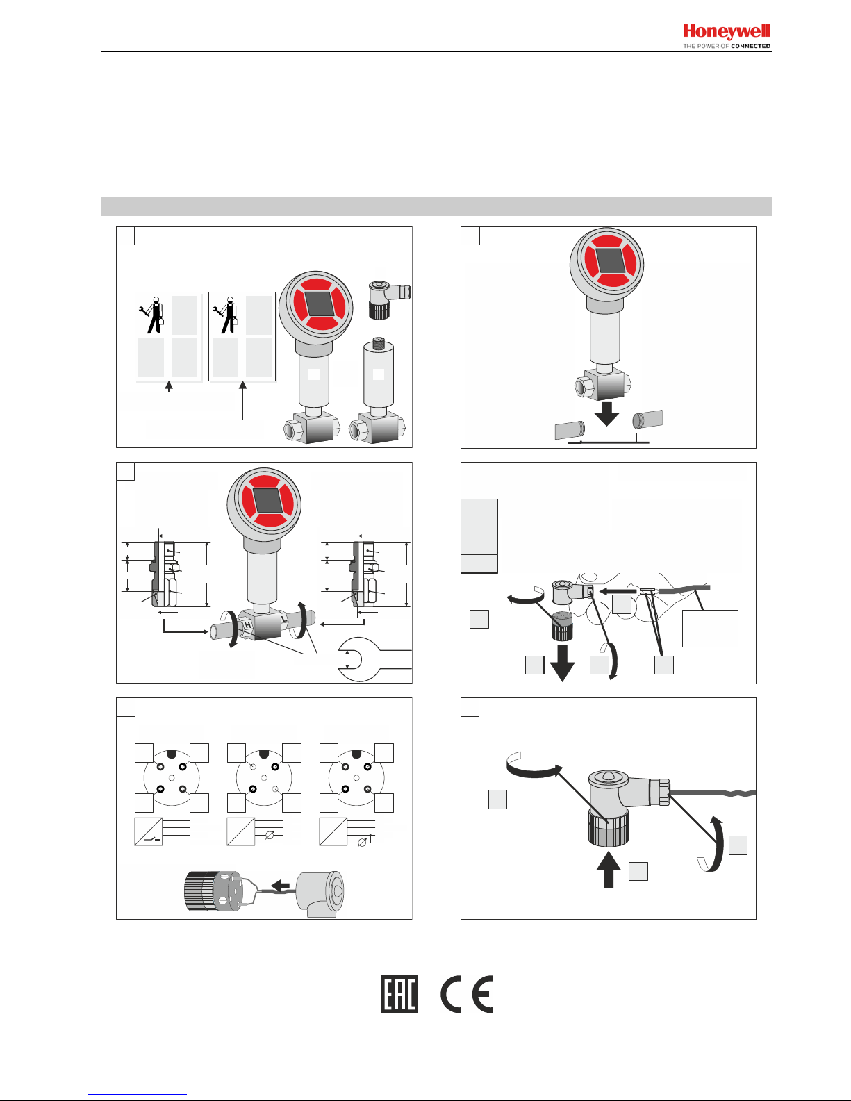
MOUNTING INSTRUCTIONS / MONTAGEANLEITUNG
1
BEFORE MOUNTING
Ensure line is
cool and not
under pressure.
IMPORTANT!
To protect sensor
against one-sided
overpressure and
possible damage
while starting
up, first install
a pressure compensation valve.
SCREWING
35
4
DEPTH
PREPARE FOR WIRING ZUR VERDRAHTUNG
3
A,B
NSCREW AND
EMOVE PLUG HEAD.
LOOSEN GLAND.
C
USE PROPER WIRE
D
END SLEEVES.
INSERT CABLE.
E
A
3-4X
{
STECKERKOPF ÖFFNEN
UND ABNEHMEN.
VERSCHRAUBUNG LÖSEN.
PASSENDE ADERNEND-
HÜLSEN VERWENDEN.
KABEL EINFÜHREN.
E
B C D
5
REASSEMBLY ZUSAMMENBAU
B
3-4X
VOR DER MONTAGE
Sicherstellen,
dass die Leitung
drucklos und
kühl ist.
Zum Schutz des Sen-
sors vor einseitiger
Überdruck und ev.
Zerstörung während
der Befüllung ist
zuerst ein Druck-
{
WICHTIG!
ausgleichshahn
einzubauen!
EINSCHRAUB-
TIEFE
MAX. 12-13 mmMAX. 12-13 mm
AWG 18 /
0.75 mm
2
4…6 mm
A
Nm
U.S Registered Trademark
Copyright © 2017 Honeywell Inc. All Rights Reserved MU1B-0402GE51 R0817D
Page 2
SMART DCM, SN DIFF (WITH/WITHOUT HMI) - MOUNTING INSTRUCTIONS
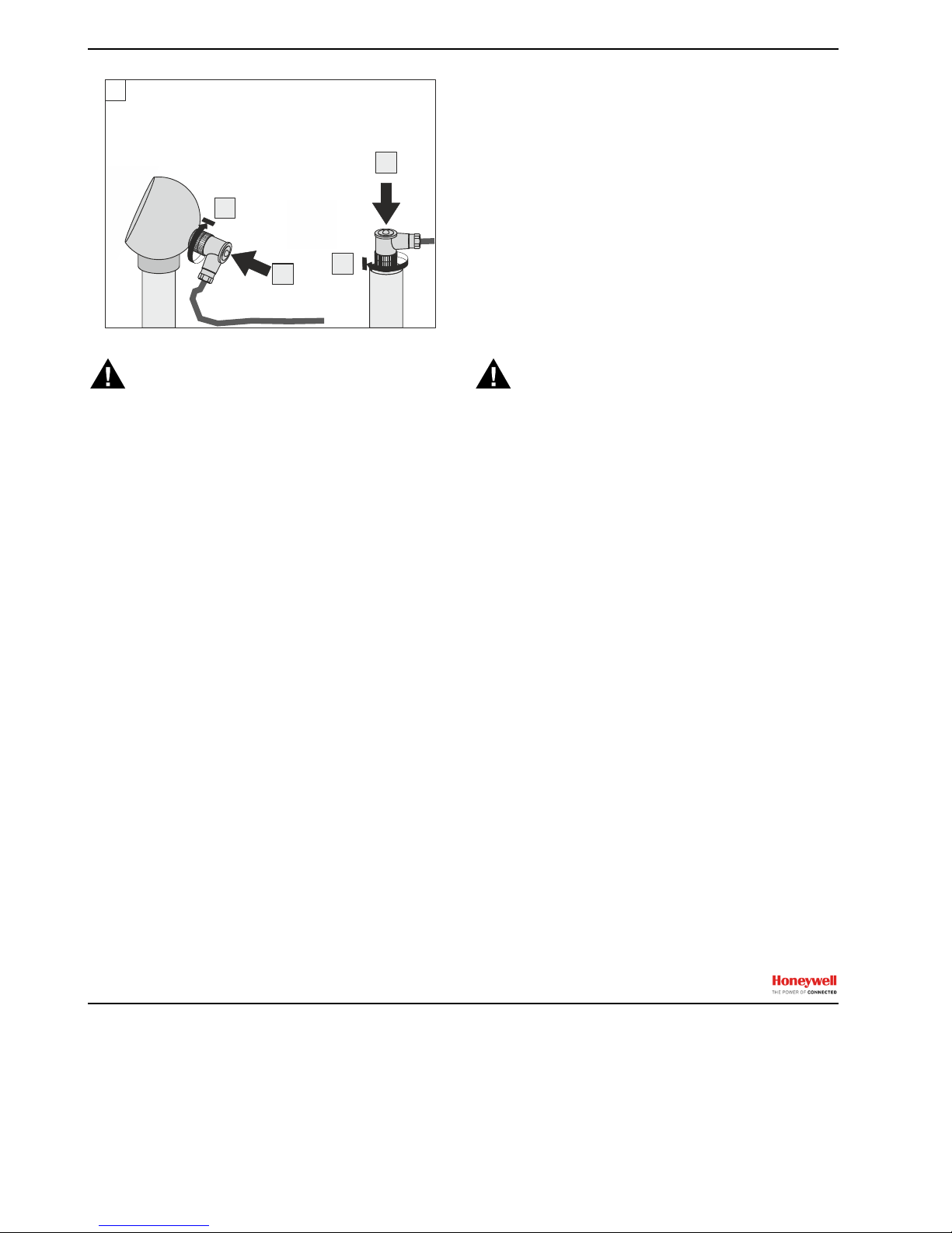
6
FASTEN PLUG
(approx. 0.5 Nm)
STECKER BEFESTIGEN
(ca. 0,5 Nm)
A
B
OR
ODER
A
B
INSTALLATION
CAUTION
Before mounting or dismounting the unit, ensure that the
system is without pressure and without electrical current!
Process parts may be hot! Danger of personal injury due to
hot process parts. Always allow the unit (and attached pipes)
to cool down before mounting / dismounting the unit.
Mounting and Orientation
The device is mounted directly to the pipe via two G¼" process connections (Width Across Flats: 19 mm). This process
connection serves to fasten and secure the device in place.
All mounting orientations are permitted.
Electrical Connection
All wiring must comply with applicable electrical codes and
local ordinances (e.g. in Germany, in accordance with VDE
regulations).
Pin Assignment of Plug
The plug is an A-coded, four-prong M12 plug (see also figure
4 on page 1).
Accessories (ordered separately)
Included in delivery: M12x1 Angled plug.
Optional: ST12-5-G (straight M12x1 plug)
MAU8/Ms adapter, 8 mm, yellow brass
MAU8/Nst adapter, 8 mm, stainless steel
INSTALLATION
VORSICHT
Vor dem Ein-/Ausbau Anlage drucklos machen und entleeren!
Spannungsfrei schalten!
Anlagenteile und Gerät können heiß sein! Verbrennungsgefahr! Gerät nur im abgekühlten Zustand montieren oder
abmontieren.
Montage und Ausrichtung
Das Gerät wird mittels zwei Prozeßanschlußgewinde G¼"
(Schlüsselweite 19 mm) direkt in die Druckleitung geschraubt.
Damit wird der Druckanschluß hergestellt und das Gerät
sicher in Position gehalten. Sämtliche Einbaulagen zulässig.
Elektrischer Anschluß
Die gesamte Verdrahtung muß gemäß den landesspezifischen Regeln und Normen durchgeführt werden (z.B.
in Deutschland nach VDE).
Kontaktbelegung des Steckers
Der Stecker ist ein A-codierter 4-poliger Stecker (siehe Bild 4
auf Seite 1).
Zubehör (extra zu bestellen)
Im Lieferumfang enthalten: M12x1 Winkelstecker.
Optional: ST12-5-G (gerader M12x1 Stecker)
MAU8/Ms Adapter, 8 mm, Messing
MAU8/Nst Adapter, 8 mm, Edelstahl
Manufactured for and on behalf of the Environmental & Energy Solutions Division of Honeywell Technologies Sàrl, Rolle, Z.A. La Pièce 16, Switzerland by its Authorized Representative:
Home and Building Technologies
Honeywell GmbH
Böblinger Strasse 17
71101 Schönaich, Germany
phone: (49) 7031-637-02
fax: (49) 7031-637-850
Subject to change without notice. Printed in Germany
MU1B-0402GE51 R0817D www.fema.biz
 Loading...