

Page 1
CT1800, CT1801, CT1802
Electromechanical Fuel Saver Thermostat and Wallplate/Subbase
CT1800 24V gas or oil heat, or 3 wire zone valves.
Installation Instructions
CT1801 24V gas or oil heat/cool.
CT1802 24V central electric heat/cool or single stage
heat pump without auxiliary heat.
Not for use on line voltage (120V) millivolt systems
Recycling Notice
This control contains mercury in a sealed tube. Do
place control in the trash at the end of its useful life.
If this control is replacing a control that contains mercury in
a sealed tube, do
not
place your old control in the trash.
M3375
not
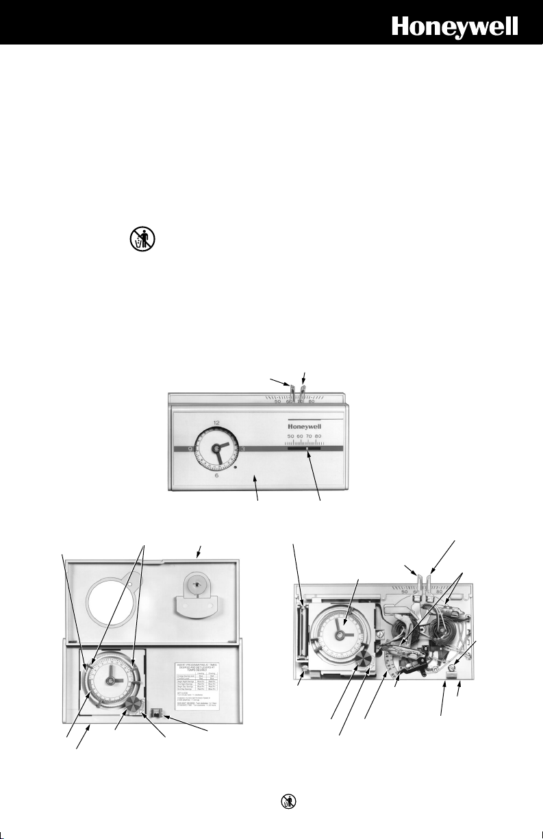
THERMOSTAT FEATURES
I—Front of thermostat.
LOW TEMPERATURE
CONTROL LEVER (BLUE)
THERMOSTAT COVER
.
Contact your local waste management authority for
instructions regarding recycling and the proper disposal of
this control, or of an old control containing mercury in a
sealed tube.
HIGH TEMPERATURE
CONTROL LEVER
(RED)
THERMOMETER
M9613
24 HOUR PROGRAM DIAL
(GRAY AREA FOR NIGHT
SETTING)
PROGRAM
PIN SLOT
THERMOSTAT COVER
III—Cover removed.II—Hinged cover lifted.
PROGRAM PINS FLIP-UP
PROGRAM
INDEX WHEEL
TIME
INDICATOR
ARROW
COVER
PROGRAM
PIN
STORAGE
M9614
D.F. • Rev. 11-96 • Printed in U.S.A. • • ©Honeywell Inc. 1996 • Form Number 69-0394—3
AAA ALKALINE
BATTERY (2) INCLUDED
24 HOUR PROGRAM DIAL
(GRAY AREA FOR
NIGHT SETTINGS)
CAPTIVE
MOUNTING
SCREW
PROGRAM
INDEX WHEEL
1 69-0394—3
M3375
ADJUSTABLE HEAT
ANTICIPATOR
TIME INDICATOR
ARROW
LOW TEMPERATURE
CONTROL LEVER
(BLUE)
HEAT
ANTICIPATOR
SETTING
LEVER
HIGH
TEMPERATURE
CONTROL LEVER
(RED)
SWITCH
BULBS
CAPTIVE
MOUNTING
SCREW
THERMOSTAT
BASE
WALLPLATE (BEHIND
THERMOSTAT. HELD
ON BY TWO CAPTIVE
SCREWS.)
M9615
Page 2
1 PREPARATION
Check thermostat and wallplate suitability for your heating or heating/cooling system. Refer to Table 1.
TABLE 1—THERMOSTAT AND SUBBASE APPLICATIONS.
Thermostat
Model
CT1800 199986B Wallplate 2- or 3- wire, 150 to 30 volt control circuit. For gas or oil heating system or
Subbase Wallplate
Included For Use With
3-wire zone valve heating system.
CT1801 Q682A1079 Subbase 4- or 5- wire, 15-30 volt control circuit. For gas or oil heating/cooling system.
CT1802 Q682B1227 Subbase 4- wire, 15 to 30 volt control circuit. For single-stage heat pump without
a
Thermostat must be mounted on wallplate or subbase included in package to assure operation.
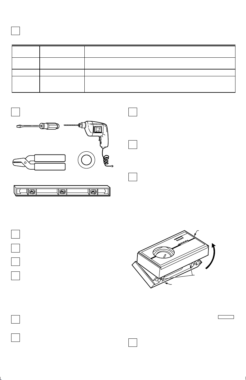
Assemble tools as required.
FLAT BLADE
SCREWDRIVER
WIRE CUTTER/STRIPPER OR SHARP
KNIFE, IF NEEDED TO STRIP WIRES
HAND OR POWER
DRILL WITH 3/16 INCH
DRILL BIT, IF NEEDED TO
DRILL HOLES IN WALL
auxiliary heat or central electric heating/cooling systems that require the
thermostat to control the fan in heating.
If wallplate or subbase is mounted on a vertical
outlet box (check old installation), order 196393A
Cover Plate and Adapter Ring (see appropriate illustration
in Step 4). To order check your telephone directory for your
local Honeywell distributor.
Test to make certain that your heating and cooling
systems are working. If either one does not work,
contact your local heating/air conditioning dealer.
NOTE: Do not operate cooling sytem if outdoor tempera-
MASKING TAPE, IF NEEDED
TO LABEL WIRES
DISCONNECTED FROM
OLD THERMOSTAT
ture is below 50°F (10°C)
Tu rn off power to the heating/cooling system at the
main fuse panel.
a
LEVEL TO LEVEL THERMOSTAT
FOR ACCURATE OPERATION
M834A
2 UNPACK THERMOSTAT
Remove and discard shipping wrap. Save package
of screws, instructions and receipt.
Remove thermostat cover by lifting up from the
bottom.
Carefully remove insert protecting switch bulbs.
Loosen two captive mounting screws, and separate
wallplate or subbase from back of thermostat base.
3 REMOVE OLD THERMOSTAT
Remove cover of old thermostat. If the cover does
not snap off when pulled firmly from the bottom,
check for a screw that locks on the cover.
Before removing the old thermostat from the wall,
look at it carefully to locate the heat anticipator
adjustment mechanism. (See illustration to help you
69-0394—3 2
THERMOSTAT
COVER
80
70
60
50
LIFT
COVER
CAPTIVE
MOUNTING
THERMOSTAT
BASE
recognize the heat anticipator.) Make a note here
of that anticipator setting for future reference. If your
thermostat does not have a heat anticipator, do not be
concerned. Move on to next paragraph.
Loosen screws holding thermostat to wallplate,
subbase or wall and lift away.
SCREWS
M9617
Page 3
BULB
SWITCH
ANTICIPATOR
SCALE
ANTICIPATOR
M6115
SETTING LEVER
Disconnect wires from old thermostat, wallplate or
subbase. Tape each end and label with the letter of
the terminal designation to make reconnection easier. If
there are only two wires labeling is not necessary.
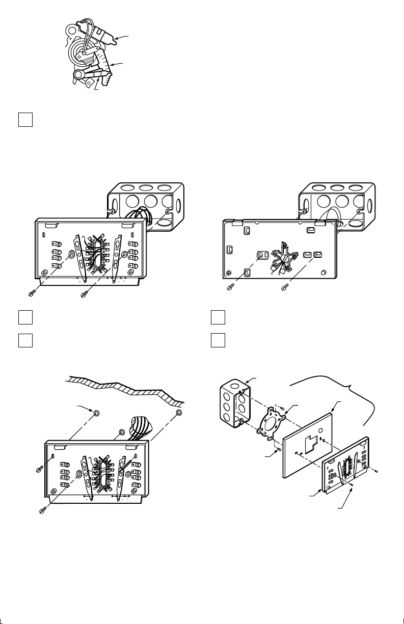
4 MOUNT WALLPLATE OR SUBBASE
IMPORTANT:
One or two extra wires?
If you are replacing a Honeywell Chronotherm
you may find one or two wires that go to the clock terminals on the Chrontherm
not allow them to touch, or you may damage your transformer. Disconnect the wires, and wrap them separately,
using electrical tape. Do not wrap them together. Place
the wires where they will not interfere with the operation of
the new thermostat. Record the colors and terminal
designation labels of the remaining wires.
If old thermostat has B or O terminals, this
thermostat cannot be used on your system.
EXCEPTION: The CT1802 Thermostat can be used
on a system with B or O terminals.
®
Thermostat,
®
Thermostat wiring wallplate. Do
EXISTING
HORIZONTAL
OUTLET BOX
O
B
R
W
G
Y
FAN
AUTO OFF
HEATON
If mounting on outlet box , mount as shown in
appropriate illustration.
When mounting on wall, hold wallplate or subbase in
position and mark holes on wall. Use level to make
sure wallplate or subbase will be level. Drill 3/16 in. holes
and gently tap anchors into holes until flush with the wall.
3 SCREW HOLES
WITH PLASTIC
ANCHORS
O
B
R
W
G
FAN
HEATING/COOLING SUBBASE
Y
AUTO OFF
HEATON
HEATING/
COOLING
SUBBASE
COOL
M1553A
COOL
M1552A
EXISTING
HORIZONTAL
OUTLET BOX
R
W
HEATING-ONLY
WALLPLATE
M856A
Position wallplate or subbase as shown in appropriate
figure, and loosely insert the screws supplied.
Carefully level the wallplate or subbase and firmly
tighten screws.
M866
MOUNTING
SCREWS (2)
VERTICAL
OUTLET
BOX
ADAPTER
RING
SUBBASE OR
WALLPLATE
MOUNTING
SCREWS (2)
COVER
PLATE
O
B
W
R
Y
G
196393A
ASSEMBLY
3 69-0394—3
Page 4

3 SCREW HOLES
WITH PLASTIC
ANCHORS
SPIRIT LEVEL
HEATING-ONLY
WALLPLATE
M9612
5 WIRE WALLPLATE OR SUBBASE
NOTE: All wiring must comply with local electrical codes
and ordinances.
Refer to illustration and strip thermostat wire
insulations as necessary.
FOR STRAIGHT
CONNECTION—
STRIP 5/16 in. [8 mm]
FOR WRAPAROUND
CONNECTION—
STRIP 7/16 in. [11 mm]
FOR CT1800 heating—only
For 2-wire system, connect either wire to R terminal
and the other wire to W terminal. For 3-wire system,
connect W wire to W terminal, R wire to R terminal, and
remaining wire to B terminal. Firmly tighten screws.
Push excess wire back into wall, and plug hole in
wall with nonflammable insulation to prevent drafts
from affecting thermostat operation.
2-WIRE SYSTEM
R
W
HEATING RELAY
OR VALVE COIL
1
POWER SUPPLY. PROVIDE DISCONNECT MEANS AND
OVERLOAD PROTECTION AS REQUIRED.
BARRIER
M1556B
L2
L1
(HOT)
M2484B
1
O
B
R
W
G
Y
FAN
AUTO OFF
COOL
HEATON
M2419
3-WIRE SYSTEM
R
W
BW
HEATING
VALVE OR
MOTOR
1
POWER SUPPLY. PROVIDE DISCONNECT MEANS AND
OVERLOAD PROTECTION AS REQUIRED.
FOR CT1801 heating/cooling
Connect the wires to matching terminals on the
subbase.
NOTE: If there are four wires, connect wire marked R to
terminal RH and add a jumper wire to connect to RC. If
RC is left unconnected, the air conditioner will not turn
on. The 4-wire drawing on page shows how to jumper
RC to RH. Strip the insulation off the wire where it
connects to the terminals. Firmly tighten screws.
If the labels do not agree with the terminal designations on
your new subbase:
• Refer to Table 2
• Determine correct hookup from the listed control
function and the equipment control circuit.
Push excess wire back into wall, and plug hole in the
wall with nonflammable insulation to prevents drafts
from affecting thermostat operation.
L2
L1
(HOT)
1
M2485B
69-0394—3 4
Page 5

4-WIRE SYSTEM
FAN
HEATING
RELAY OR
VALVE COIL
2
RC
RH
W
G
Y
AUTO OFF
HEATON
COOLING
FAN
CONTACTOR
RELAY
COIL
5-WIRE SYSTEM
RC
RH
W
G
Y
COOL
HEATING
RELAY OR
VALVE COIL
FAN
AUTO OFF
HEATON
COOLING
FAN
CONTACTOR
RELAY
COIL
COOL
1
L1
(HOT)
L2
1
POWER SUPPLY. PROVIDE DISCONNECT MEANS AND
OVERLOAD PROTECTION AS REQUIRED.
2 INSTALL JUMPER BETWEEN RC AND RH.
M2414
1
L1
(HOT)
L2
1
POWER SUPPLY. PROVIDE DISCONNECT MEANS AND
OVERLOAD PROTECTION AS REQUIRED.
TABLE 2—TERMINAL DESIGNATIONS.
Subbase Terminal Control Function
R or RH Heating transformer power to control circuit
RX Cooling transformer power to control circuit
W Heating relay or valve
Y Cooling relay
G Fan relay
B Heating changeover valve or damper control circuit
O Cooling changeover valve or damper control circuit
P Heat pump compressor control circuit.
FOR CT1802 heating/cooling
Connect the wires to matching terminals on the
subbase. Firmly tighten screws.
Push excess wire back into wall, and plug hole in
wall with nonflammable insulation to prevent drafts
from affecting thermostat operation.
CENTRAL ELECTRIC SYSTEM
Y
W
B
P
R
O
G
FAN
AUTO OFF
COOLING
CONTACTOR
COIL
1
POWER SUPPLY. PROVIDE DISCONNECT MEANS AND
OVERLOAD PROTECTION AS REQUIRED.
FAN
RELAY
HEATON
HEATING
RELAY OR
VALVE COIL
COOL
L2
L1
(HOT)
1
M2412A
SINGLE STAGE HEAT PUMP
(WITHOUT AUXILIARY HEAT) SYSTEM
COMPRESSOR
CONTACTOR
COIL
1
POWER SUPPLY. PROVIDE DISCONNECT MEANS AND
OVERLOAD PROTECTION AS REQUIRED.
2
IF COMPRESSOR IS CONNECTED TO OLD THERMOSTAT'S
"Y" TERMINAL WITH A JUMPER TO "W", USE NEW THERMOSTAT'S
"P" TERMINAL FOR COMPRESSOR. IF OLD THERMOSTAT HAS
ONE WIRE TO "Y" AND ONE TO "W", USE "Y" AND "W" ON NEW
THERMOSTAT; DO NOT USE "P". IMPORTANT– IF OLD
THERMOSTAT USES A W2 (AUXILIARY OR EMERGENCY HEAT)
TERMINAL, THIS THERMOSTAT MAY NOT BE USED. THIS
THERMOSTAT IS NOT DESIGNED TO CONTROL AUXILIARY HEAT.
3
SOME HEAT PUMPS USE "B" INSTEAD OF "O".
3
FAN
Y
W
2
B
P
R
O
G
AUTO OFF
HEATON
REVERSING
VALVE
COOL
FAN
RELAY
L2
L1
(HOT)
L1
(HOT)
L2
M2415B
1
M2413
5 69-0394—3
Page 6

6 MOUNT THE THERMOSTAT
Note the tabs on the top inside edge of the thermostat
base. These fit the slots molded into the top of the
wallplate or subbase.
Hang the thermostat base on the wallplate or
subbase as shown in illustration.
Insert the two captive mounting screws located in
the bottom corners of the thermostat base (see
illustration); firmly tighten.
IMPORTANT:
Do not cycle heating system until step 7 is
completed.
7 SET HEAT ANTICIPATOR LEVER
The thermostat adjustable heat anticipator must be
correctly set to accurately control the on-time length
of the system. An incorrect setting can result in room
temperature swings or burn out the anticipator and void the
thermostat warranty.
Make sure you have the current draw (anticipator setting)
for your system. This is the number you wrote in the box in
Step 3. If you were unable to find the current draw for Step 3,
this information can be found printed on the primary control
at the furnace or boiler. The primary control is usually a gas
SHOWS
VOLTAGE
RATING
SHOWS
ANTICIPATOR
SETTING
8406
V8043E 1004 4
24V 50/60CY
@ 60CY
.32 AMP
ZONE VALVE
SHOWS
VOLTAGE
RATING
FROM MAIN
FUEL SUPPLY
TYPICAL GAS VALVE
TAB (2)
MOUNTING SLOT (2)
1
1
2
2
3
11
4
1
0
5
9
6
8
7
7
8
6
9
10
1
1
12
35
0
3
5
2
20
0
1
CAPTIVE
MOUNTING SCREWS
OIL BURNER CONTROL
30 VAC
0.2 AMP
TO
BURNER
SHOWS
ANTICIPATOR
SETTING
WALLPLATE
OR SUBBASE
SHOWS
CURRENT
DRAW
THERMOSTAT
M3408
BASE
valve, a relay or burner control box, Aquastat controller or
zone valve with the thermostat wires connected to it. These
controls are usually located behind the furnace cover. See
next illustration.
If current rating is still unavailable, proceed as follows:
• Connect the probes of an ac ammeter (0 to 2.0A for
example) between the R (or RH) and W terminals on
the wallplate or subbase.
• Let the system operate through the ammeter for at least
one minute before taking reading. Record the reading
here .
24 Vac 50/60 Hz
0.4 AMP
JUMPER WIRES
SHOWS
VOLTAGE
RATING
T
T
F
F
M6116B
Move the heat anticipator to match the number you
recorded in Step 3 or found on the primary control
as shown above, or as recorded in Step 7.
ANTICIPATOR
SCALEPLATE
ANTICIPATOR
SETTING LEVER
69-0394—3 6
IMPORTANT:
Most hot water systems require a setting of
1.3 times the valve current rating.
M9616
Page 7

8 INSTALL CLOCK BATTERIES
Power is supplied to the clock by two AAA alkaline
batteries (included). Install clock batteries in
thermostat as shown. Once a year, or when batteries are
dead, replace with two new AAA alkaline batteries. We
recommend Energizer
are more likely to leak, which could damage the clock. The
thermostat itself will operate without batteries, but will not
operate as a fuel saver.
®
batteries. Other types of batteries
9 SET CLOCK
Adjust the clock by moving the minute hand in
clockwise direction. Do
When time is correctly set, the Time Indicator Arrow
(see illustration) must point to the correct time and
the corresponding daytime (light) or nighttime (dark)
portion of the program dial.
not
reverse the minute hand.
10 ATTACH THERMOSTAT COVER
Make sure the packing inserts in the thermostat
base have been removed, as explained in Step 2.
Place the two tabs on upper edges of cover into the
mounting slots in the thermostat base.
Swing cover downward until it engages catch at
bottom of base.
BATTERY LOCATION
FOR (2) AAA BATTERIES;
INSTALL WITH POSITIVE
ENDS UP
M9618
M9619
PROGRAM
INDEX
WHEEL
TIME
INDICATOR
ARROW
M2499
11 CHECKOUT THERMOSTAT OPERATION AND SET TEMPERATURE CONTROL LEVERS
The two levers on top of the thermostat control the
low and high temperature for energy savings and
comfort control as shown in the illustration.
LOW TEMPERATURE
(BLUE MARK)
SET LEVER
50
60
70
80
HIGH TEMPERATURE
(RED MARK)
SET LEVER
M859
7 69-0394—3
CAUTION
Do
not
check operation by shorting across
terminals of relay or valve coil; this will burn out the
thermostat heat anticipator, which will void the
warranty.
Heating-Only System
Tu rn on power to the furnace.
Page 8

Push both temperature control levers together at
least 5°F (3°C) above room temperature. The heat
should come on. The fan will start when the furnace heats
up,
Move both levers 5°F (3°C) below room temperature.
The heat should shut off.
Operate the entire heating system for at least one
complete cycle.
IMPORTANT:
Heating/Cooling System
should come on. The fan will start when the furnace heats
up. On the CT1802, the fan will start immediately.
stop when the furnace cools.
IMPORTANT:
equipment should operate, and the fan will start. Allow for
any time delay that may be built into the compressor
control circuit.
If thermostat fails any test, refer to the
Tr oubleshooting Guide in Owner’s manual.
Tu rn on power to the furnace and cooling system.
Place the system switch lever at HEAT and the fan
switch lever at AUTO.
Push both temperature control levers together at
least 5°F (3°C) above room temperature. The heat
Move both levers together at 5°F (3°C) below room
temperature. The heat should shut off. The fan will
To avoid compressor damage, do not
operate the cooling system if outdoor temperature is
below 50
°
F (3°C) below room temperature. The heat
should shut off. The fan will stop when the furnace
cools.
Place the system switch level at COOL and the fan
switch lever at AUTO.
Push both temperature control levers together at
least 5°F (3°C) below room temperature. The cooling
Move both levers together 5°F (3°C) above room
temperature. The cooling equipment should shut off.
Place the fan switch at ON. The fan should run
continuously with the system in any position.
Place the system switch at OFF. Move both
temperature levers to various positions. The heating
and cooling systems should not operate.
Operate the entire system for at least one complete
cycle with the system switch at COOL and one
complete cycle with the switch at HEAT.
IMPORTANT:
For heating season:
home is not occupied.
For cooling season:
home is not occupied.
Refer to the owner’s manual form 69-0333 for operating
and programming instructions.
If thermostat fails any test, refer to trouble-
shooting guide in owner’s manual.
After checkout, reset both temperature levers to
desired temperatures.
Move the
blue
temperature you want when you are sleeping or your
Set the
normal
Move the
temperature you want when you are sleeping or your
Set the
normal
lever to the
red
lever to the temperature you want for
comfort periods.
red
lever to the
blue
lever to the temperature you want for
comfort periods.
energy savings
energy savings
If you have questions regarding the thermostat please If you have questions regarding the Honeywell Fuel Saver
Thermostat please visit our web site at www.honeywell.com/yourhome, or call the customer information line at
1-800-468-1502.
Helping You Control Your World
69-0394—3 8
69-0846 4
www.honeywell.com/yourhome
 Loading...