

Page 1
®
CR7075
Two-Stage Lighting Controller
PRODUCT DATA
FEATURES
• Light intensity threshold levels field-adjustable
by user.
• Independent Time of Day (TOD) override inputs.
• Optimum start/stop of lighting loads.
• Tamper-proof cover.
• LED annunciation for power on and relay state.
• Wide ambient temperature range.
• Up to 1000-foot separation between photocell
and controller.
APPLICATION
The CR7075A Two-Stage Lighting Controller offers on/off
sequenced control of two separate lighting banks based
on user determined ambient light intensity level via a
single sensor. Typical applications include outdoor cosmetic
and parking lot lighting in fast food restaurants, retail
establishments, supermarkets, banks, and lighted billboards.
Contents
Application ........................................................................ 1
Features ........................................................................... 1
Specifications ................................................................... 2
Ordering Information ........................................................ 2
Installation ........................................................................ 3
Operation .......................................................................... 6
Checkout .......................................................................... 7
® U.S. Registered Trademark
Copyright © 2001 Honeywell • All Rights Reserved
63- 2180- 1
Page 2
CR7075 TWO-STAGE LIGHTING CONTROLLER
SPECIFICATIONS
Model: CR7075A1000 Two-Stage Lighting Controller.
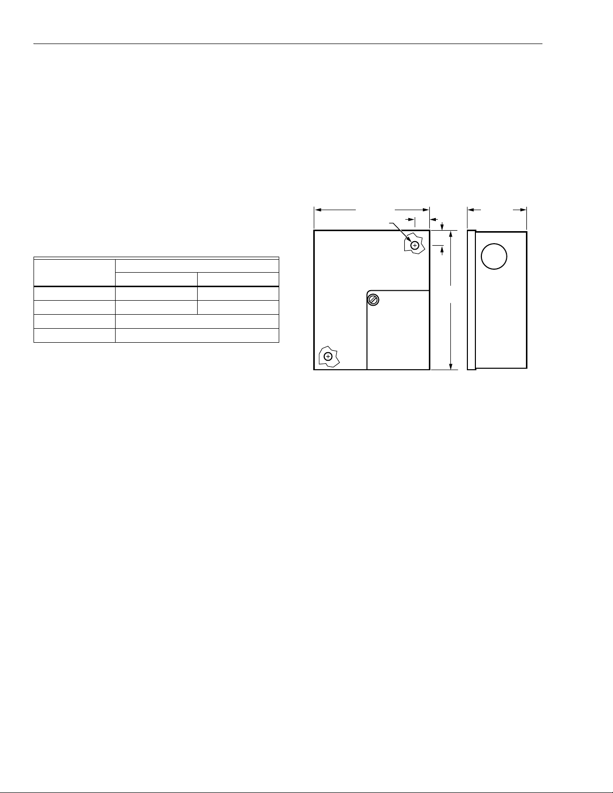
Dimensions: See Fig. 1.
Electrical Ratings:
Voltage Input: 120/240 Vac, 50/60 Hz.
Power Consumption: 5 VA Maximum.
Switching: Single-Pole, Double-Throw (SPDT).
Sensor: Cadmium sulfide photocell (C7057A1000),
1000 ft. maximum distance between sensor and controller,
shielded wire not required.
Indicators: LED annunciation—power and relay state.
Contact Ratings:
Voltage (Vac)
120 240
Full Load 9.8A 4.9A
Locked Rotor 58.8A 29.4A
Pilot Duty 125VA
Resistive 10A @ 24 Vac
TOD Inputs: Two independent contact closure inputs.
Function is active when contact closure is made between
appropriate terminals.
Integrating Time Delay: 30 ±10 seconds.
Ambient Temperature Range: -40 to +140°F (-40 to 60°C).
Humidity: 0 to 95% rh.
Setpoint Range: 2 foot-candles to 80 foot-candles.
Approvals:
Underwriter’s Laboratories, Inc. Listed: File No. E87741,
Guide No. EOXT.
Canadian Standards Association Listed.
4-9/16 (116)
MOUNTING HOLES (2)
3/8
(10)
3/8
(10)
5-5/16
(135)
2-1/4 (57)
M17971
Fig. 1. Approximate CR7075 dimensions in in. (mm).
ORDERING INFORMATION
When purchasing replacement and modernization products from your TRADELINE® wholesaler or distributor, refer to the
TRADELINE® Catalog or price sheets for complete ordering number.
If you have additional questions, need further information, or would like to comment on our products or services, please write or
phone:
1. Your local Home and Building Control Sales Office (check white pages of your phone directory).
2. Home and Building Control Customer Relations
Honeywell, 1885 Douglas Drive North
Minneapolis, Minnesota 55422-4386 (800) 328-5111
In Canada—Honeywell Limited/Honeywell Limitée, 35 Dynamic Drive, Scarborough, Ontario M1V 4Z9.
International Sales and Service Offices in all principal cities of the world. Manufacturing in Australia, Canada, Finland, France,
Germany, Japan, Mexico, Netherlands, Spain, Taiwan, United Kingdom, U.S.A.
63-2180—1 2
Page 3
CR7075 TWO-STAGE LIGHTING CONTROLLER
M
INSTALLATION
When Installing this Product...
1. Read these instructions carefully. Failure to follow
them could damage the product or cause a hazardous
condition.
2. Check the ratings given in the instructions and on the
product to make sure the product is suitable for your
application.
3. Installer must be a trained, experienced service
technician.
4. After installation is complete, check out product
operation as provided in these instructions.
CAUTION
Electrical Shock or Equipment Damage Hazard.
Can shock individuals or short equipment
circuitry.
Disconnect power supply before installation.
Before Installation
IMPORTANT
Expose the photocell to light for 16 hours.
The photocells develop a hysteresis (or “light memory”) when
packed for shipping. Until the photocell has been exposed to
bright light for at least 16 hours, light level setpoints will shift.
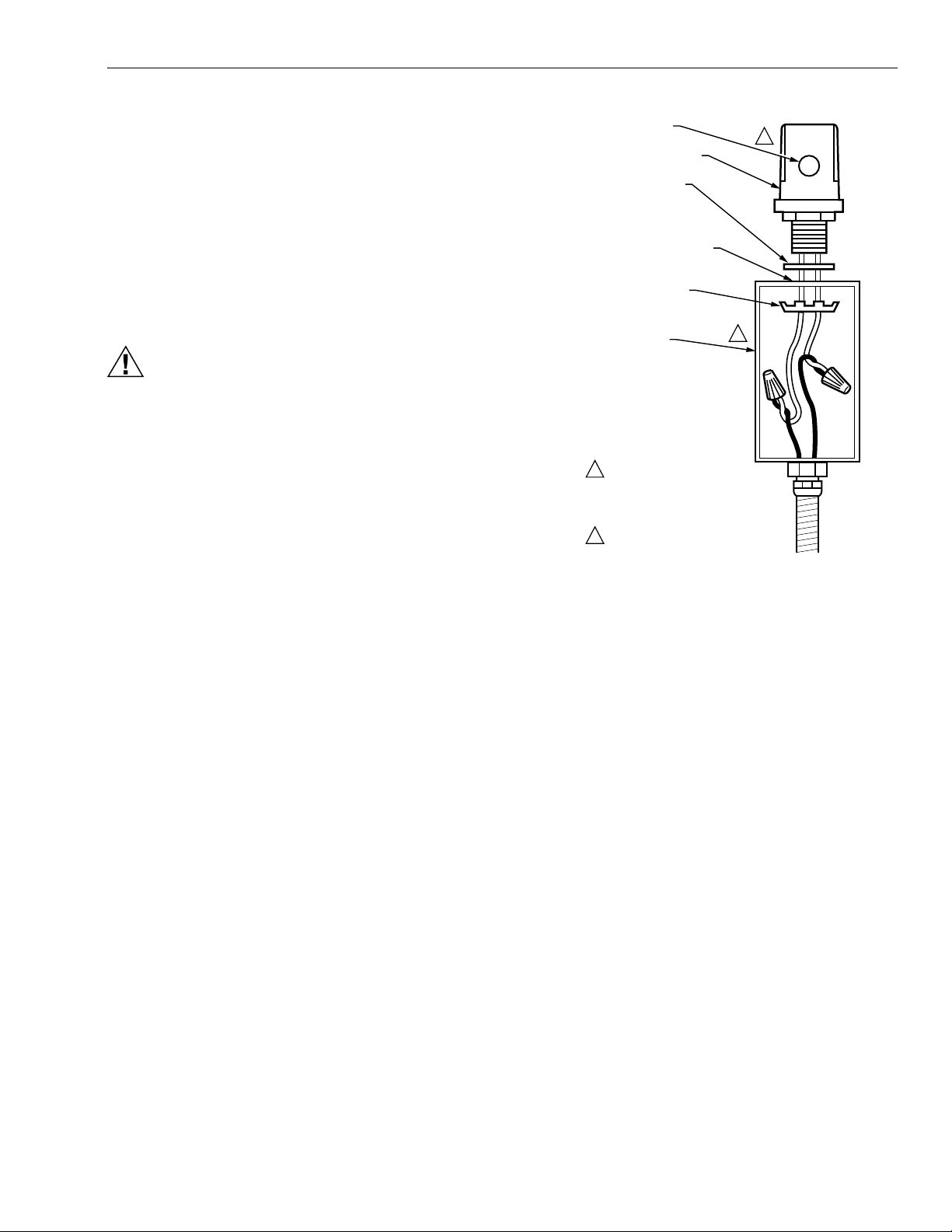
20060
LENS
PHOTOCELL
GASKET
1/2-14 THREADED
KNOCKOUT OR
7/8 INCH HOLE
HEX NUT
JUNCTION
BOX
1
FOR BEST RESULTS, EXPOSE LENS
TO LIGHT FROM THE NORTHERN SKY
(IN THE NORTHERN HEMISPHERE)
OR THE SOUTHERN SKY (IN THE
SOUTHERN HEMISPHERE).
2
USE WATERTIGHT JUNCTION BOX
WITH PROPER GASKETS AND SEALS.
1
2
Fig. 2. Vertical mounting configuration.
Location
Locate the cadmium sulfide photocell sensor C7057A1000
(supplied with this controller) so that the lens is exposed to full
daylight. (See Fig. 2.)
NOTES:
— Select an area which will not become shaded.
— Mount only with light entrance facing horizontally.
— Avoid overexposure to direct east/west sunlight.
Mounting
IMPORTANT
Mount the photocell sensor to the top of a watertight,
outdoor FS junction box.
1. Use the gasket provided to prevent moisture entry.
2. Screw stem into 1/2-14 threaded knockout.
NOTE: The photocell sensor can be mounted in a
7/8 in. hole (or knockout).
Mount the controller on any convenient interior location:
1. Remove the tamper-proof cover.
2. Mount the controller using the two mounting holes
provided in the metal enclosure corners (mounting
screws not included).
NOTE: Use controller dimensions in Fig. 1 as a guide.
3 63-2180—1
Page 4

CR7075 TWO-STAGE LIGHTING CONTROLLER
A
B
E
T
T
Wiring
CAUTION
Electrical Shock or Equipment Damage Hazard.
Can shock individuals or short equipment
circuitry.
Disconnect power supply before installation.
IMPORTANT
• All wiring must agree with applicable codes,
ordinances and regulations.
• When wiring the input power, apply only one source
of power to the CR7505A.
• With line-voltage loads, the power and load voltage
must be the same.
Refer to chart on the inside of the controller cover or Fig. 3 for
locating the power inputs, photocell sensor inputs, TOD and
load relay terminals. Refer to Fig. 4 through 7 for typical wiring
and application examples.
NOTES:
— The photocell sensor has no polarity.
— Wire to terminal strip T2, terminals 4 and 5.
— Access to the terminals can be gained through
standard conduit knockouts (A-E) located around
the perimeter of the enclosure.
— Use knockout A only for the photocell sensor
and TOD wiring.
— Photocell wires should be at least 18 AWG two
conductor. If not run in watertight conduit, use
suitable insulation for outdoor wiring.
— Shielded wiring is not required.
C
CAUTION
ONE POWER SOURCE ONLY
LINE POWER
240
120
VAC
COM
VAC
N0 COM
SET
T.O.D. 1
T.O.D. 2
SENSOR
OUTPUT 1
RUN
POWER
NC
7
8
9
10
STAGE 1
N0 COM NC
D
OUTPUT 2
LIGHT LEVEL
56
4
7
3
8
2
9
1
10
STAGE 2
56
4
3
2
1
M1040
Fig. 3. Knockout locations and internal device layout.
WHITE
L1
BLACK
L2
1
CAUTION
ONE POWER SOURCE ONLY
LINE POWER
240
120
COM
VAC
VAC
LOAD 1
OUTPUT 1
N0
COMNCN0 COM NC
LOAD 2
OUTPUT 2
The Two-Stage Lighting Control System consists of
two components:
— CR7075 Two-Stage Lighting Controller.
— C7057 Cadmium Sulfide Photocell Sensor.
This system offers independent series 60 control of two
separate lighting banks based on user determined ambient
light intensity level via a single sensor.
Set point indexing is relative. The SET-RUN switch removes
the integrating time delay (short cycle protection) circuitry in
the SET position. In the RUN position (normal operation) there
is a 30 ±10 second time delay for both light fall and light rise
initiated relay action.
Two independent Time Of Day (TOD) inputs are provided to
override a relay energized condition of either output. This
function is generated by a contact closure from an EMS
controller or time clock with normally open contacts, i.e.,
W7505, S7005, etc., between terminals 1 and 2 (stage 1) and
terminals 2 and 3 (stage 2) of terminal strip T2 (Fig. 6 and 7).
These inputs have priority over any time delay action.
SET
RUN
LIGHT LEVEL
56
4
7
10
STAGE 1
7
3
8
2
9
1
10
STAGE 2
.O.D. 1
.O.D. 2
POWER SUPPLY. PROVIDE DISCONNECT MEANS AND
1
OVERLOAD PROTECTION AS REQUIRED.
1
T.O.D. 1
2
T.O.D. 2
3
T2
POWER
4
SENSOR
5
8
9
Fig. 4. Wiring for 120 or 240 Vac input and load.
56
4
3
2
1
M1043
63-2180—1 4
Page 5

CR7075 TWO-STAGE LIGHTING CONTROLLER
.
1
)
WHITE
L1
1
BLACK
L2
CAUTION
ONE POWER SOURCE ONLY
LINE POWER
120
VAC
T.O.D. 1
T.O.D. 2
1
POWER SUPPLY. PROVIDE DISCONNECT MEANS
AND OVERLOAD PROTECTION AS REQUIRED.
2
WHEN SWITCHING 24 VOLT LOADS MAKE SURE BARRIER IS INSTALLED
LOAD 1 LOAD 2
2
OUTPUT 1
240
N0 COMNCN0 COM NC
COM
VAC
SET
1
T.O.D. 1
2
T.O.D. 2
3
T2
4
SENSOR
5
RUN
POWER
7
8
9
10
STAGE 1
OUTPUT 2
LIGHT LEVEL
56
4
7
3
8
2
9
1
10
STAGE 2
56
Fig. 5. Wiring for 120 Vac input; 24 Vac load.
L1
(HOT
1
L
L2
WHITE
1
L2
BLACK
S7005
CAUTION
ONE POWER SOURCE ONLY
LINE POWER
240
120
VAC
N0 COMNCN0 COM NC
COM
VAC
OUTPUT 1
LOAD 2LOAD 1
OUTPUT 2
T3 T4 T5
SET
RUN
LIGHT LEVEL
56
56
4
3
2
1
POWER SUPPLY. PROVIDE DISCONNECT MEANS
1
AND OVERLOAD PROTECTION AS REQUIRED.
M1042
1
T.O.D. 1
2
T.O.D. 2
3
T2
SENSOR
POWER
4
5
7
8
9
10
STAGE 1
4
4
7
3
3
8
2
9
10
STAGE 2
2
1
M1088
1
Fig. 6. Wiring for 120 Vac input and load;
S7005 Microprogrammer controlling both
TOD inputs from a single output.
L1
RELAY 1 RELAY 2
W7505
RELAY 3
RELAY 4 RELAY 5
WHITE
1
L2
BLACK
CAUTION
ONE POWER SOURCE ONLY
LINE POWER
120
COM
VAC
240
VAC
OUTPUT 1
N0 COM
NC
LOAD 2LOAD 1
OUTPUT 2
N0 COM NC
RUN
POWER SUPPLY. PROVIDE DISCONNECT MEANS
1
AND OVERLOAD PROTECTION AS REQUIRED.
SET
1
T.O. D. 1
2
T.O. D. 2
3
T2
4
5
POWER
SENSOR
7
8
9
10
STAGE 1
LIGHT LEVEL
56
4
7
3
8
2
9
1
10
STAGE 2
56
4
3
2
1
M1089
Fig. 7. Wiring for 120 Vac input and load; W7075 Building Management System controlling both TOD inputs.
5 63-2180—1
Page 6

CR7075 TWO-STAGE LIGHTING CONTROLLER
(
(
OPERATION
In many applications, outdoor cosmetic lighting and parking lot
lighting activate either simultaneously or with independent
controllers by means of a time of day clock with a photocell
override. The photocell override turns on lighting during
abnormal weather conditions (such as overcast sky).
NOTE: Overriding the time of day feature with a photocell
controller provides optimum lighting control, but does
not maximize energy savings.
The Two-Stage Lighting Controller overcomes the energy
saving and calibration deficiencies mentioned above. Each
stage functions separately to control the on/off times of the
outdoor cosmetic and parking lot lighting.
NOTE: At the time of installation, one can operationally
check the photocell by covering the lens with their
hand from a distance of a few inches.
IMPORTANT
Calibration is accomplished by setting light level
potentiometers to turn the lights on at the userdetermined ambient light level.
After a period of time, the photocell characteristics can
change due to accumulation of airborne particles on the lens.
Certain environmental conditions (such as high humidity
levels) can accelerate this accumulation. This can require
changing the light level potentiometer settings. (Refer to the
Checkout section for calibration instructions.)
Typical Sequencing
The following is an example of a typical on/off sequence.
NOTES:
— Refer to Fig. 8 for sequence of operation.
— For 24-hour stores, lights simply remain on unless
sufficient light exists to warrant their shut-off. As
operation in such an arrangement depends only
on the photocell, TOD override need only operate
on a manual basis.
Typical Evening Start-up
As ambient light level decreases, cosmetic lighting (stage 1)
turns on first. As ambient light level decreases further, parking
lot lights (stage 2) turn on. Both turn off after the business
closes using a separate time of day clock. If desired,
independent TOD override for each stage allows turning off
one stage at a different time than the other.
LIGHT
INTENSITY
LOW
STAGE 2
SETPOINT
ADJUSTABLE)
STAGE 1
SETPOINT
ADJUSTABLE)
HIGH
M1045
DECREASING LIGHTING CONDITIONS
STAGE 1 - ON
(SUNSET)
TIME
DELAY
STAGE 2 - ON
TIME
DELAY
TIME
Fig. 8. Sequence of operation.
Typical Morning Start-up
Both cosmetic and parking lot lighting turn on with the time of
day clock. If desired, independent TOD override for each
stage allows turning on one stage at a different time than the
other. As ambient light level increases, the parking lot lights
(stage 2) turn off first and the cosmetic lighting (stage 1) turns
off last as the ambient light level increases further.
63-2180—1 6
Page 7

CHECKOUT
CR7075 TWO-STAGE LIGHTING CONTROLLER
In the following procedures, refer to the diagram inside the
CR7075A cover or Fig. 3. These show locations of all
operating controls, LED lights, and wiring connection points.
Initial Adjustments
1. Adjust both light level potentiometers to the fully
clockwise position (#1 index level).
2. Place the SET-RUN switch to the RUN position.
Calibration
After the controller and photocell sensor are installed (with
wiring and settings verified), and the photocell has been
exposed to light for 16 hours, apply power. The light intensity
threshold levels can be calibrated when the desired outdoor
light level has occurred.
NOTES:
— Calibration achieves best results when making
adjustments at or near the light conditions
required for switching the equipment.
— Attempting calibration at extreme light conditions
can cause switching to be unachievable.
1. At the desired outdoor light level place SET-RUN switch
to the SET position.
2. Slowly rotate stage 1 light level potentiometer counterclockwise until the stage 1 LED lights.
3. Stage 1 is now calibrated to the light level existing at the
sensor and the stage 1 load is energized.
4. Return the SET-RUN switch to the RUN position.
NOTE: To calibrate stage 2, repeat this process
except adjust the stage 2 light level
potentiometer.
IMPORTANT
After initial setup is complete, make certain the
switch is in the RUN position to avoid short cycling
the loads.
NOTE: The SET-RUN switch removes the integrating time
delay (short-cycle protection) circuitry in the SET
position. In the RUN position (normal operation) the
calibrated light level must be present for 30 seconds
before the load switches.
7 63-2180—1
Page 8

Home and Building Control Home and Building Control Honeywell International Honeywell Europe Honeywell Latin American
Honeywell Honeywell Limited-Honeywell Limitée Home and Building Control S.A. Region
1985 Douglas Drive North 35 Dynamic Drive Honeywell Building 3 Avenue du Bourget 480 Sawgrass Corporate Parkway
Golden Valley, MN 55422 Scarborough, Ontario 17 Changi Business Park Central 1 1140 Brussels Suite 200
M1V 4Z9 Singapore 486073 Belgium Sunrise FL 33325
63-2180—1 B.B. Rev. 9-01 www.honeywell.com
Printed in U.S.A. on recycled
paper containing at least 10%
post-consumer paper fibers.
 Loading...