

Page 1
TrueZONE® Bypass (CPRD)
M34207
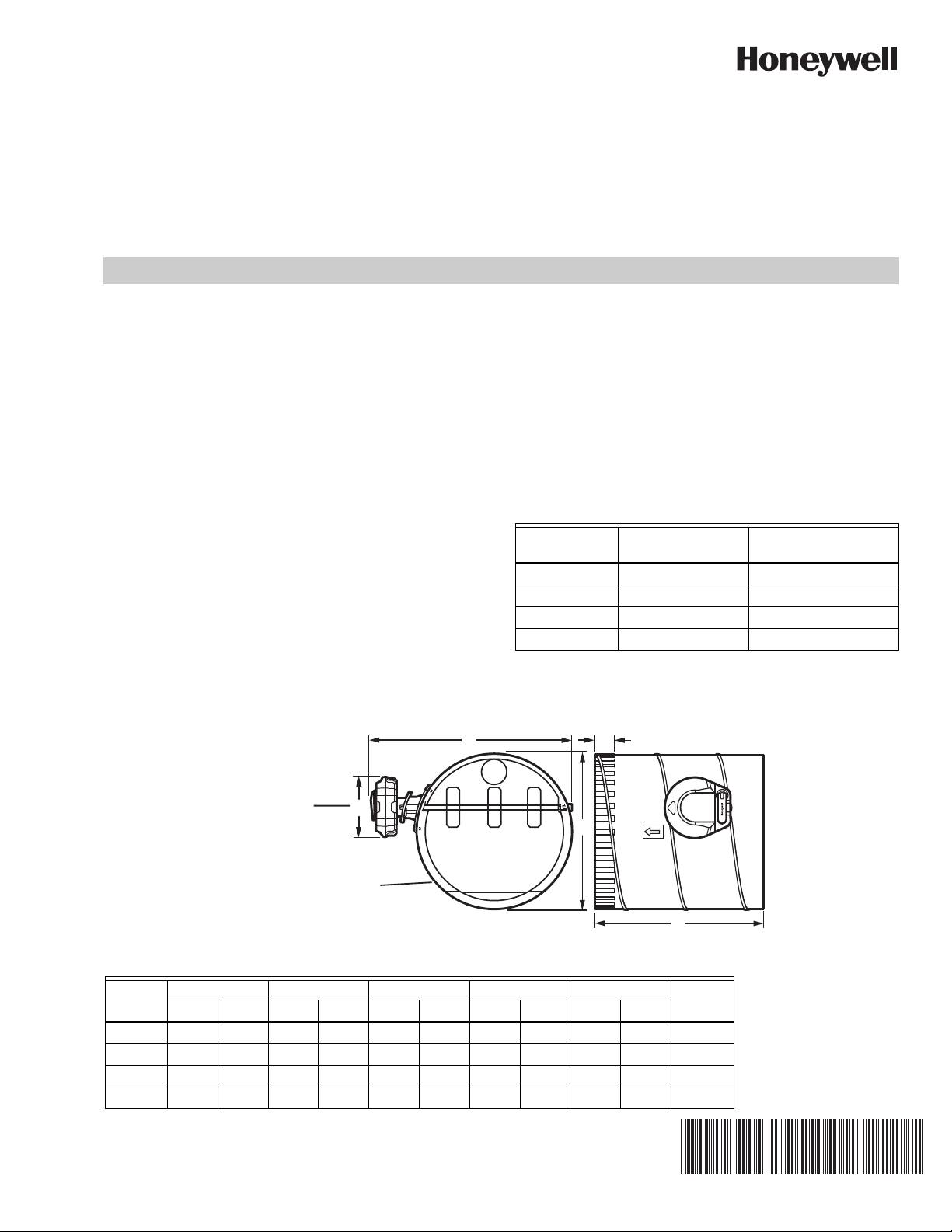
D
E
B
C
A
Regulator
Damper
INSTALLATION INSTRUCTIONS
APPLICATION
The TrueZONE® Bypass constant pressure regulating damper
(CPRD) is a round static pressure relief damper. It is used in
forced-air bypass applications to relieve excess static
pressure when some of the zone dampers are closed. The
damper is installed in a duct that delivers air to the return or a
dump zone. The damper automatically opens and closes to
maintain a desired static pressure.
The CPRD uses a calibrated spring to regulate the bypass air
accurately when any number or combination of zones is
calling. Conventional, weighted arm, bypass dampers may
operate properly when one zone is calling; however, when
different combinations of zones are calling, they bypass too
much or too little. This can cause callbacks when
homeowners complain of air noise.
Selecting the Correct CPRD
1. Size the bypass damper by subtracting the cfm of the
smallest zone from the cfm of the system.
2. Consult Table 1 to determine the CPRD to use.
3. Example:
Bypass CFM = Total System CFM - Smallest Zone CFM
DIMENSIONS
SPECIFICATIONS
Construction:
Galvanized steel, see Table 2
Temperature Range:
Ambient: 0F–165F (-17C–73C)
Storage: 30F–150F (-1C– 65C)
Table 1. Damper Sizing
Bypass
Damper
CPRD8 CPR8 600 CFM
CPRD10 CPR10 1000 CFM
CPRD12 CPR12 1400 CFM
CPRD14 CPR14 1700 CFM
Replacement
Regulator Maximum Airflow
Table 2. CPRD Dimensions.
ABCDE
Model
CPRD8 8 203.2 9.65 245 1.50 38 11.54 292.84 4.65 118 26
CPRD10 10 254 11.42 290 1.50 38 13.50 343 4.65 118 26
CPRD12 12 305 13.18 235 1.50 38 15.47 392.84 4.65 118 24
CPRD14 14 355 14.96 380 1.50 38 17.36 441 4.65 118 22
Gaugein mm in mm in mm in mm in mm
69-2770EFS-03
Page 2
TRUEZONE® BYPASS (CPRD)
INSTALLATION
Select Damper Location
Install the CPRD onto a starting collar or in duct that loops
from supply to return. The supply side take-off must be before
any zone dampers. It is best to install the return side of this
loop as far a practical from the air handler.
The CPRD can be mounted in vertical or horizontal ductwork,
or at any angle. The damper may also be rotated to be
installed with the regulator on either side, top or at any angle
between.
Secure the damper to sheet metal ductwork with screws or to
flex-duct with tape. If ducting with flex-duct, the outer layer of
plastic can be taped to the damper mounting flange to fully
insulate the damper.
Alternatively, the CPRD can dump air from the supply to a
non-critical temperature area such as a hallway, basement, or
false ceiling.
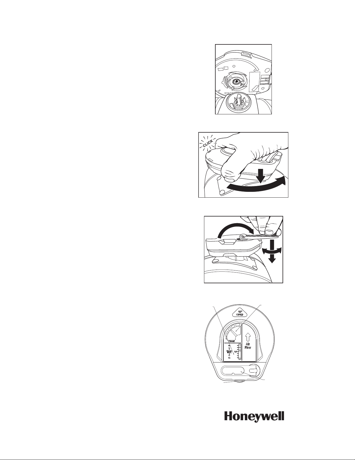
Attach Regulator to Damper
1. Align the regulator with the "D" shaft on the damper (see
Fig. 1).
2. Slide the regulator onto the "D" shaft and push down
while turning counterclockwise until it snaps into place
(see Fig. 2).
Fig. 1.
M34208
M34209
Fig. 2.
Setting the Regulator
The CPRD is factory set to open at approximately .5"WC."
This setting is satisfactory for most installations. Some
systems have higher static pressure.Test this by:
1. Make all zones call fan, heat, or cool; whichever has the
highest CFM.
2. Verify that the damper position indicator points to
closed.
3. If it does not point to closed:
• Flip the adjustment crank out (see Fig. 3)
• Push down on the adjustment crank with gentle
pressure. Caution: Do not rotate the adjustment
crank without first pushing it down
• Turn the adjustment crank clockwise until the
indicator points to closed
• When done, flip the adjustment crank back into the
locked position
4. Make only the smallest zone call for fan, heat, or cool.
5. Verify that the airflow into that zone is not objectionable.
If it is, then set the regulator to a lower pressure.
Removing the Regulator
If you need to remove the regulator from the damper, do so by
pressing the red release button. See Fig. 4. It is easier to
remove the regulator after turning the pressure down to a
lower setting.
PRESSURE SETTING
INDICATOR
RELEASE
BUTTON (RED)
Fig. 4. CPRD regulator
Fig. 3.
DAMPER POSITION
INDICATOR
M34211
M34210
ADJUSTMENT
CRANK
Automation and Control Solutions
Honeywell International Inc.
1985 Douglas Drive North
Golden Valley, MN 55422
customer.honeywell.com
® U.S. Registered Trademark
© 2012 Honeywell International Inc.
69-2770EFS—03 M.S. Rev. 12-12
Printed in United States
Page 3
Dérivation TrueZONE® (CPRD)
MF34207
D
E
B
C
A
Régulateur
Registre
NOTICE D’INSTALLATION
APPLICATION
Le registre de régulation de pression constante (CPRD) de
dérivation TrueZONE
rond. Il est utilisé dans les applications de dérivation à air
pulsé pour limiter la pression statique en excès lorsque
certains registres de zone sont fermés. Le registre s'installe
dans une gaine fournissant de l'air à la zone de retour ou
d'évacuation. Le registre s'ouvre et se ferme automatiquement
pour maintenir la pression statique désirée.
Le CPRD utilise un ressort étalonné pour réguler avec
précision l'air de dérivation en cas d'appel de diverses zones
ou combinaisons de zones. Les registres de dérivation à bras
lesté conventionnels peuvent fonctionner adéquatement en
cas d'appel d'une seule zone; toutefois, lorsque diverses
combinaisons de zones lancent un appel, la dérivation est
insuffisante ou excessive. Ceci peut causer des retours de
produits lorsque les propriétaires se plaignent du bruit causé
par l'air.
®
est un registre de pression statique
Sélection du CPRD correct
1. Dimensionner le registre de dérivation en soustrayant la
superficie de la zone la plus petite de la capacité du système.
2. Consulter le Tableau 1 pour déterminer le CPRD à
utiliser.
3. Exemple : Superficie dérivation = Capacité totale du
système - Superficie de la zone la plus petite
CARACTÉRISTIQUES
Construction : Acier galvanisé, voir le Tableau 2
Plage de température :
Ambiante : 0 °F-165 °F (-17 °C-73 °C)
Stockage : 30 °F-150 °F (-1 °C-65 °C)
Tableau 1. Dimensionnement du registre.
Registre de
dérivation
CPRD8 CPR8 600 CFM
CPRD10 CPR10 1000 CFM
CPRD12 CPR12 1200 CFM
CPRD14 CPR14 1400 CFM
Régulateur de
rechange
Débit d'air
maximum
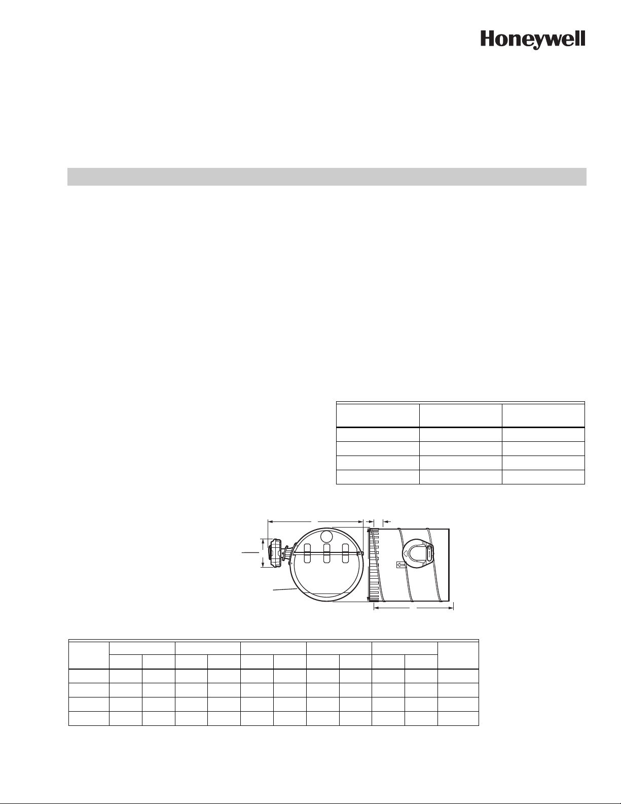
DIMENSIONS
Tableau 2. Dimensions du CPRD
ABCDE
Modèle
CPRD8 8 203,2 9,65 245 1,50 38 11,54 292,84 4,65 118 26
CPRD10 10 254 11,42 290 1,50 38 13,50 343 4,65 118 26
CPRD12 12 305 13,18 235 1,50 38 15,47 392,84 4,65 118 24
CPRD14 14 355 14,96 380 1,50 38 17,36 441 4,65 118 22
Calibrepo mm po mm po mm po mm po mm
Page 4

DÉRIVATION TRUEZONE® (CPRD)
MF34209
INSTALLATION
Sélection de l'emplacement du registre
Installer le CPRD sur un collet de départ ou dans une gaine
faisant une boucle de l'alimentation au retour. L'appel côté
alimentation doit être situé avant tout registre de zone. Il est
recommandé d'installer le côté retour de cette boucle aussi
loin que possible d'un niveau pratique du système de
traitement de l'air.
Le CPRD peut être monté dans une gaine horizontale ou
verticale, ou à tout autre angle. Le registre peut aussi être
tourné pour être installé avec le régulateur d'un côté ou de
l'autre, en haut, ou à tout angle intermédiaire.
Fixer le registre sur une gaine en tôle avec des vis ou sur des
tuyaux flexibles avec du ruban à conduits . Si des tuyaux
flexibles sont présents, la couche externe du plastique peut
être collée sur la bride de montage du registre avec du ruban
à conduits pour isoler complètement le registre.
Le CPRD peut aussi évacuer l'air de l'alimentation vers une
zone de température non critique telle qu'un couloir, un soussol ou un faux-plafond.
Fixation du régulateur au registre
1. Aligner le régulateur sur l'arbre « D » du registre (voir la
Fig. 1).
2. Faire glisser le régulateur sur l'arbre « D » et le pousser
vers le bas tout en tournant dans le sens antihoraire
jusqu'à ce qu'il s'enclenche en position (voir la Fig. 2).
Retrait du régulateur
S'il est nécessaire de retirer le régulateur du registre, appuyer
sur le bouton de libération rouge pour ce faire. Voir la Fig. 4. Il
est plus facile de retirer le régulateur après avoir réduit la
pression.
M34208
Fig. 1.
Fig. 2.
Réglage du régulateur
Le CPRD est réglé en usine pour s'ouvrir à environ 0,5 po c.e.
Ce réglage satisfait à la plupart des installations. Certains
systèmes ont une pression statique supérieure. Vérifier cela
de la façon suivante :
1. Lancer un appel de ventilateur, chauffage ou refroid-
issement sur toutes les zones; noter celle qui a la plus
grande superficie.
2. Vérifier que l'indicateur de position du registre pointe sur
la position de fermeture.
3. S'il ne pointe pas sur la position de fermeture
• Dégager le bras de réglage (voir la Fig. 3).
• Pousser le bras de réglage vers le bas en appliquant
une légère pression. Mise en garde : Ne pas faire
tourner le bras de réglage sans l'avoir abaissé au
préalable.
• Tourner le bras de réglage dans le sens horaire
jusqu'à ce que l'indicateur pointe sur la position de
fermeture.
• Une fois ceci terminé, faire pivoter le bras de réglage
en position de verrouillage.
4. Ne lancer un appel de ventilateur, chauffage ou refroid-
issement que pour la zone la plus petite.
5. Vérifier que le débit d'air dans cette zone ne pose pas
de problème. Si c'est le cas, régler le régulateur à une
pression inférieure.
Fig. 3.
INDICATEUR
DE RÉGLAGE
DE PRESSION
BOUTON
DE LIBÉRATION
(ROUGE)
Fig. 4. Régulateur CPRD
MF34211
M34210
INDICATEUR
DE POSITION
DU REGISTRE
BRAS
DE RÉGLAGE
69-2770EFS—03 2
Page 5

DÉRIVATION TRUEZONE® (CPRD)
Solutions de régulation et d’automatisation
Honeywell International Inc.
1985 Douglas Drive North
Golden Valley, MN 55422
customer.honeywell.com
® Marque de commerce déposée aux États-Unis
© 2012 Honeywell International Inc.
Tous droits réservés
69-2770EFS—03 M.S. Rev. 12-12
Imprimé aux États-Unis
Page 6

Desviador de paso TrueZONE®
MS34207
D
E
B
C
A
Controlador
Regulador
(CPRD)
INSTRUCCIONES PARA LA INSTALACIÓN
APLICACIÓN
El desviador de paso TrueZONE® del regulador para el
control de la presión constante (CPRD) es un regulador
circular para el alivio de la presión estática. Se utiliza en
aplicaciones de derivación de aire forzado para aliviar el
exceso de presión estática cuando algunos de los
reguladores de zona están cerrados. El regulador se instala
en un conducto que suministra aire al conducto de retorno o a
una zona de descarga. El regulador se abre y se cierra
automáticamente para mantener la presión estática deseada.
El CPRD utiliza un resorte calibrado para regular la derivación
del aire de forma precisa cuando se produce cualquier
cantidad o combinación de demanda de zonas. Los
reguladores de derivación convencionales, con brazo de
contrapeso, pueden funcionar adecuadamente cuando una
zona emita una demanda; sin embargo, cuando se emiten
diferentes combinaciones de demandas en las zonas, estas
derivarán demasiado o muy poco aire. Esto puede ocasionar
llamadas al servicio técnico cuando los propietarios
residenciales se quejan del ruido causado por el aire.
Cómo seleccionar el CPRD adecuado
1. Dimensione el regulador de derivación restando los
PCM de la zona más pequeña de los PCM del sistema.
2. Consulte la tabla 1 para determinar el CPRD que debe
usar.
3. Ejemplo: Derivación PCM = PCM total del sistema -
PCM de la zona más pequeña.
ESPECIFICACIONES
Construcción: Acero galvanizado, consulte la tabla 2.
Rango de temperatura:
Ambiente: 0 °F a 165 °F (-17 °C a 73 °C)
Almacenaje: 30 °F a 150 °F (-1 °C a 65 °C)
Tabla 1. Cómo dimensionar el regulador.
Regulador de
desviación
CPRD8 CPR8 600 PCM
CPRD10 CPR10 1000 PCM
CPRD12 CPR12 1200 PCM
CPRD14 CPR14 1400 PCM
Controlador de
reemplazo
Máximo flujo de
aire
DIMENSIONES
Tabla 2. Dimensiones CPRD
ABCDE
Modelo
CPRD8 8 203.2 9.65 245 1.50 38 11.54 292.84 4.65 118 26
CPRD10 10 254 11.42 290 1.50 38 13.50 343 4.65 118 26
CPRD12 12 305 13.18 235 1.50 38 15.47 392.84 4.65 118 24
CPRD14 14 355 14.96 380 1.50 38 17.36 441 4.65 118 22
Calibrepo mm po mm po mm po mm po mm
Page 7

DESVIADOR DE PASO TRUEZONE® (CPRD)
MF34209
INSTALACIÓN
Selección de la ubicación del regulador
Instale el CPRD en un anillo de arranque o en un conducto
que vaya del suministro al retorno. La toma del lado del
suministro debe estar antes de cualquier regulador de zona.
Es mejor instalar el lado de retorno de este ciclo tan alejado
como sea posible del controlador de aire.
El CPRD puede montarse en el sistema de conductos vertical
u horizontal o en cualquier ángulo. El regulador también
puede rotarse para ser instalado con el controlador en
cualquiera de los dos lados, en la parte superior o en
cualquier ángulo entre ellos.
Fije el regulador al sistema de conductos de lámina metálica
con tornillos o al conducto flexible con cinta. Si utiliza
conductos flexibles, la capa externa de plástico puede
encintarse a la pestaña de montaje del regulador para aislarlo
completamente.
Como alternativa, el CPRD puede descargar aire del
suministro en un área de temperatura que no sea crítica tal
como un pasillo, sótano o techo falso.
Fije el controlador al regulador
1. Alinee el controlador con el eje "D" del regulador (con-
sulte la Fig. 1).
2. Deslice el controlador hasta el eje "D" y presione hacia
abajo mientras lo gira en sentido antihorario hasta que
calza en su lugar (consulte la Fig. 2).
Retiro del controlador
Si necesita retirar el controlador del regulador, hágalo
presionando el botón de desbloqueo rojo. Consulte la Fig. 4.
Es más fácil retirar el controlador después de colocar la
presión en una configuración más baja.
M34208
Fig. 1.
Fig. 2.
Configuración del controlador
El CPRD está configurado de fábrica a aproximadamente 0.5
"c. a.". Esta configuración es adecuada para la mayoría de las
instalaciones. Algunos sistemas tienen mayor presión
estática. Pruebe esto así:
1. Haga que todas las zonas emitan una demanda de ven-
tilación, calefacción o refrigeración; la que tenga mayor
PCM.
2. Verifique que los indicadores de posición del regulador
estén orientados hacia la posición cerrada.
3. Si no están orientados hacia la posición cerrada:
• Mueva la manivela de ajuste hacia afuera (consulte
la Fig. 3).
• Presione suavemente hacia abajo la manivela de
ajuste. Precaución: No gire la manivela de ajuste sin
presionarla primero hacia abajo.
• Gire la manivela de ajuste en sentido horario hasta
que el indicador esté orientado hacia la posición
cerrada.
• Cuando termine, mueva la manivela de ajuste
nuevamente a la posición bloqueada.
4. Efectúe solo la demanda de zona más pequeña para
ventilación, calefacción o refrigeración.
5. Verifique que el flujo de aire en esa zona no sea
objetable. Si lo es, configure el controlador a menor presión.
Fig. 3.
INDICADOR
DE CONFIGURACIÓN
DE PRESIÓN
BOTÓN
DE DESBLOQUEO
(ROJO)
Fig. 4. Controlador de CPRD.
MS34211
M34210
INDICADOR
DE POSICIÓN
DEL REGULADOR
MANIVELA
DE AJUSTE
69-2770EFS—03 2
Page 8

DESVIADOR DE PASO TRUEZONE® (CPRD)
Automatización y control desenlace
Honeywell International Inc.
1985 Douglas Drive North
Golden Valley, MN 55422
customer.honeywell.com
® Marca Registrada en los Estados Unidos
© 2012 Honeywell International Inc. todos
Los Derechos Reservados
69-2770EFS—03 M.S. Rev. 12-12
Impreso en Estados Unidos
 Loading...