

Page 1
Honeywell BW Solo User Manual
Honeywell
Rev. A
P/N: G05-4001-000
BWTM Solo User Manual
1
October 2018
Page 2

Honeywell BW Solo User Manual
Product Registration
IMPORTANT! BUMP TEST THE MONITOR BEFORE EACH DAY’S USE
Register your product online by visiting:
https://www.honeywellanalytics.com/en/support/product-registration
By registering your product, you can:
• Receive notification of product upgrades or enhancements
• Be alerted to training classes in your area
• Take advantage of special offers and promotions
Prior to each day’s use, every gas detection monitor should be bump tested to confirm the response of
all sensors and activation of all alarms by exposing the monitor to a concentration of target gas that
exceeds the low alarm set point. A bump test is also recommended if the monitor has been subjected to
physical impact, liquid immersion, an Over Limit alarm event, or custody changes, or anytime the
monitor’s performance is in doubt.
To ensure greatest accuracy and safety, only bump test and calibrate in a fresh air environment.
The monitor should be calibrated every time it does not pass a bump test, but no less frequently than
every six months, depending on use and exposure to gas and contamination, and its operational mode.
• Calibration intervals and bump test procedures may vary due to national legislation.
• Honeywell recommends using calibration gas cylinders containing the gas that is appropriate to the
sensor you are using, and in the correct concentration.
© 2018 Honeywell International.
2
Page 3

Honeywell BW Solo User’s Guide
Contents
1. Standard Contents ................................................................................................................................. 9
2. General Information ............................................................................................................................... 9
3. User Interface & Display Overview ...................................................................................................... 10
3.1. Out-Of-Box Experience (First Time Use Only) ............................................................................ 11
3.2. Status Indicator Icons .................................................................................................................. 12
4. BLE (Bluetooth Low Energy) Operation .............................................................................................. 12
4.1. BLE Icons .................................................................................................................................... 13
4.2. Non-Compliance Indicator LEDs ................................................................................................. 13
4.3. Pairing With Smartphones ........................................................................................................... 14
5. Battery ................................................................................................................................................. 17
5.1. Battery Status .............................................................................................................................. 17
5.2. Battery Replacement ................................................................................................................... 17
6. Turning The Honeywell BW Solo On & Off ......................................................................................... 19
6.1. Turning The Honeywell BW Solo On .......................................................................................... 19
6.2. Turning The Honeywell BW Solo Off .......................................................................................... 19
6.3. Calibration Status ........................................................................................................................ 19
6.4. Bump Status ................................................................................................................................ 20
6.5. Sensor Fault Status ..................................................................................................................... 20
7. Navigation ............................................................................................................................................ 21
7.1. Glance Navigation ....................................................................................................................... 21
7.2. Main Navigation ........................................................................................................................... 22
8. Navigation: Information Menu ............................................................................................................. 23
8.1. Event Log Navigation .................................................................................................................. 24
9. Navigation: Settings ............................................................................................................................. 25
9.1. Enter Settings Mode .................................................................................................................... 25
9.2. Menus & Submenus In Settings Mode ........................................................................................ 26
9.3. Language..................................................................................................................................... 27
9.4. Time ............................................................................................................................................. 27
9.5. Date ............................................................................................................................................. 27
9.6. Units ............................................................................................................................................ 27
9.7. Readings ..................................................................................................................................... 27
9.8. Setpoints ...................................................................................................................................... 28
9.9. Latching ....................................................................................................................................... 28
9.10. Reminders ................................................................................................................................... 28
9.10.1. Force On or Off for Bump/Cal ............................................................................................... 28
9.10.1.1. Force Cal ................................................................................................................ 28
9.10.1.2. Force Bump ............................................................................................................ 29
9.11. Data Logging ............................................................................................................................... 29
9.12. BLE .............................................................................................................................................. 29
9.13. Assigned ...................................................................................................................................... 29
9.14. Zone ............................................................................................................................................ 29
9.15. IntelliFlash ................................................................................................................................... 30
9.16. Non-Compliance Indicator LEDs ................................................................................................. 30
9.17. Passcode ..................................................................................................................................... 31
9.18. Exit ............................................................................................................................................... 31
3
Page 4

Honeywell BW Solo User Manual
10. Zeroing ................................................................................................................................................ 32
11. Bump Testing ...................................................................................................................................... 32
12. Calibrating ........................................................................................................................................... 34
13. Replacing The Filter & Sensor ............................................................................................................ 35
13.1. Filter Color Reference ................................................................................................................. 35
13.2. Removing The Cover .................................................................................................................. 35
13.3. Replacing The Filter .................................................................................................................... 36
13.4. Replacing The Sensor ................................................................................................................. 36
13.4.1. 4-Series Sensor Replacement .............................................................................................. 37
13.4.2. 1-Series Sensor Replacement .............................................................................................. 39
13.5. Reinstalling The Cover ................................................................................................................ 41
14. Maintenance ........................................................................................................................................ 42
14.1. Cleaning ...................................................................................................................................... 42
14.2. Replacing The Alligator Clip ........................................................................................................ 42
14.3. Replacing/Servicing Other Parts ................................................................................................. 42
15. Firmware Update ................................................................................................................................. 42
16. Year Of Manufacture ........................................................................................................................... 42
17. Sensors & Settings .............................................................................................................................. 43
18. Troubleshooting ................................................................................................................................... 45
19. Honeywell BW Solo Specifications ...................................................................................................... 46
20. Limited Warranty and Limitation of Liability ......................................................................................... 48
4
Page 5
Honeywell BW Solo User Manual
WARNINGS
This Manual must be carefully read by all individuals who have or will have the responsibility of using, maintaining,
or servicing this product. The product will perform as designed only if it is used, maintained, and serviced in
accordance with the manufacturer’s instructions. The user should understand how to set the correct parameters and
interpret the obtained results.
For safety reasons, this equipment must be operated and serviced by qualified personnel only. Read and
understand the user manual completely before operating or servicing.
AVERTISSEMENT
Pour des raisons de sécurité, cet équipment doit être utilisé, entretenu et réparé uniquement par un personnel
qualifié. Étudier le manuel d’instructions en entier avant d’utiliser, d’entretenir ou de réparer l’équipement.
Read Before Operating
This manual must be carefully read by all individuals who have or will have the responsibility of using, maintaining,
or servicing this product. The product will perform as designed only if it is used, maintained, and serviced in
accordance with the manufacturer’s instructions. The user should understand how to set the correct parameters and
interpret the obtained results.
CAUTION!
To reduce the risk of electric shock, turn the power off before opening this instrument or performing service. Never
operate the instrument when the instrument is open. Service this product only in an area known to be nonhazardous.
Proper Product Disposal At End Of Life
EU Directive 2012/19/EU: Waste Electrical and Electronic Equipment (WEEE)
This symbol indicates that the product must not be disposed of as general industrial or domestic
waste. This product should be disposed of through suitable WEEE disposal facilities. For more
information about disposal of this product, contact your local authority, distributor, or the
manufacturer.
5
Page 6

This product is a gas detector, not a measurement device.
• Ensure that the sensor cap is free of dirt, debris, and is not obstructed.
• Clean the exterior with a soft, damp cloth.
• For optimal performance, periodically zero the sensor in a normal atmosphere (20.9% v/v O
hazardous gas.
• Portable safety gas detectors are life safety devices. Accuracy of ambient gas reading(s) is dependent upon
factors such as accuracy of the calibration gas standard used for calibration and frequency of calibration.
Honeywell Analytics recommends performing a calibration at least once every 180 days (6 months).
• Any rapid up-scaling reading followed by a declining or erratic reading may indicate a gas concentration
beyond the upper scale limit, which can be hazardous.
• Products may contain materials that are regulated for transportation under domestic and international
dangerous goods regulations.
• Return product in compliance with appropriate dangerous goods regulations. Contact freight carrier for further
instructions.
• Recycling: this instrument contains a lithium battery. Do not mix with the solid waste stream. Spent batteries
should be disposed of by a qualified recycler or hazardous materials handler.
Wireless Security Warning
Wireless data transmission can extend beyond your walls and can be received by anyone with a compatible
adapter. Without proper protection, data can be compromised. Use the security features of all wireless
equipment in your network.
• Bluetooth communication should always be set to OFF unless the functionality is required.
• If possible, pair devices ONLY when in a physically secure area.
Honeywell BW Solo User Manual
CAUTION!
) that is free of
2
6
Page 7

Caution
Honeywell BW Solo User Manual
This device complies with Part 15 of the FCC Rules / Industry Canada license-exempt RSS standard(s). Operation is
subject to the following two conditions: (1) this device may not cause harmful interference, and (2) this device must
accept any interference received, including interference that may cause undesired operation.
Le présent appareil est conforme aux CNR d'Industrie Canada applicables aux appareils radio exempts de licence.
L'exploitation est autorisée aux deux conditionssuivantes : (1) l'appareil ne doit pas produire de brouillage, et (2)
l'utilisateur del'appareil doit accepter tout brouillage radioélectrique subi, même si le brouillage estsusceptible d'en
compromettre le fonctionnement.
Changes or modifications not expressly approved by the party responsible for compliance could void the user's
authority to operate the equipment.
This equipment has been tested and found to comply with the limits for a Class B digital device, pursuant to part 15 of
the FCC Rules. These limits are designed to provide reasonable protection against harmful interference in a
residential installation. This equipment generates uses and can radiate radio frequency energy and, if not installed
and used in accordance with the instructions, may cause harmful interference to radio communications. However,
there is no guarantee that interference will not occur in a particular installation. If this equipment does cause harmful
interference to radio or television reception, which can be determined by turning the equipment off and on, the user is
encouraged to try to correct the interference by one or more of the following measures:
• Reorient or relocate the receiving antenna.
• Increase the separation between the equipment and receiver.
• Connect the equipment into an outlet on a circuit different from that to which the receiver is connected.
• Consult the dealer or an experienced radio/TV technician for help.
Under Industry Canada regulations, this radio transmitter may only operate using an antenna of a type and maximum
(or lesser) gain approved for the transmitter by Industry Canada. To reduce potential radio interference to other users,
the antenna type and its gain should be so chosen that the equivalent isotropically radiated power (e.i.r.p.) is not more
than that necessary for successful communication.
Conformément à la réglementation d'Industrie Canada, le présent émetteur radio peutfonctionner avec une antenne
d'un type et d'un gain maximal (ou inférieur) approuvé pour l'émetteur par Industrie Canada. Dans le but de réduire
les risques de brouillage radioélectrique à l'intention des autres utilisateurs, il faut choisir le type d'antenne et son gain
de sorte que la puissance isotrope rayonnée équivalente (p.i.r.e.) ne dépasse pas l'intensité nécessaire à
l'établissement d'une communication satisfaisante.
7
Page 8

Honeywell BW Solo User’s Guide
Operation Area and Conditions
Safety Certifications
Class I, Division 1, Groups A,B,C,D T4; Class I, Zone 0, AEx/Ex ia IIC T4 Ga
-40°C≤ Tamb ≤ 60°C
ATEX: Sira 19ATEX2004, 0518 II
Tamb -40°C to 60°C
IECEx: IECEx SIR 19.0004 Ex ia IIC T4 Ga / Ex ia I Ma Tamb = -40°C to +60°C
1G I M1 / Ex ia IIC T4 Ga / Ex ia I Ma
INSTRUCTIONS FOR SAFE USE
WARNING: Read and understand instruction manual before operation or servicing.
AVERTISSEMENT: Lisez et comprenez le manual d’instructions avant d’utiliser ou d'effectuer
l'entretien.
WARNING: Substitution of components may impact safety.
AVERTISSEMENT: La substitution de composants peut compromettre la sécurité.
WARNING: Lithium battery: Only use approved battery: 2/3AA 3.6V 1.65Ah Lithium battery
(P/N: BWS-BAT01).
AVERTISSEMENT: Batterie Lithium: Utilisez uniquement des batteries approuvé: 2/3AA 3.6V
1.65Ah Batterie Lithium (N/P: BWS-BAT01).
8
Page 9

Honeywell BW Solo User Manual
1. Standard Contents
Standard Package includes:
• Detector complete with specified sensor, stainless-steel alligator clip and concussion-proof
housing
• Test Cap with 1 ft of hose
• Quick Reference Guide
2. General Information
Honeywell BW Solo is easy to operate — even if you’re wearing gloves. Using this button or the
Honeywell SafetySuite Device Configurator software, you can easily configure set points, latching
alarms, and other parameters. You can also access measurements for short-term exposure limit
(STEL) and time-weighted average (TWA), and pair the wireless Honeywell BW Solo with our
mobile apps:
• With the Device Configurator app, you can set up the detector, choose alarm set points and
more — all from up to 6 meters away. Also use the app to see calibration readings, email
calibration certificates and upgrade firmware.
• With the Safety Communicator app, detector readings are sent instantly to Honeywell’s realtime monitoring software. Access it from any device with an internet connection, and get
remote visibility on worker safety and location.
You can also use the wireless Honeywell BW Solo to share gas data with the desktop software —
no dock required.
Key Features
• Simple one-button operation
• Easy sensor, filter, and battery replacement
• Compatible with IntelliDoX for centralized data with automated bump testing, calibration, and
• Option to activate IntelliFlash™ or non-compliance flash
• Ability to assign detectors to workers and locations
• Easy-to-read display for multiple languages
• Data logging with rolling 24-hour peak reading
instrument management.
9
Page 10
Honeywell BW Solo User Manual
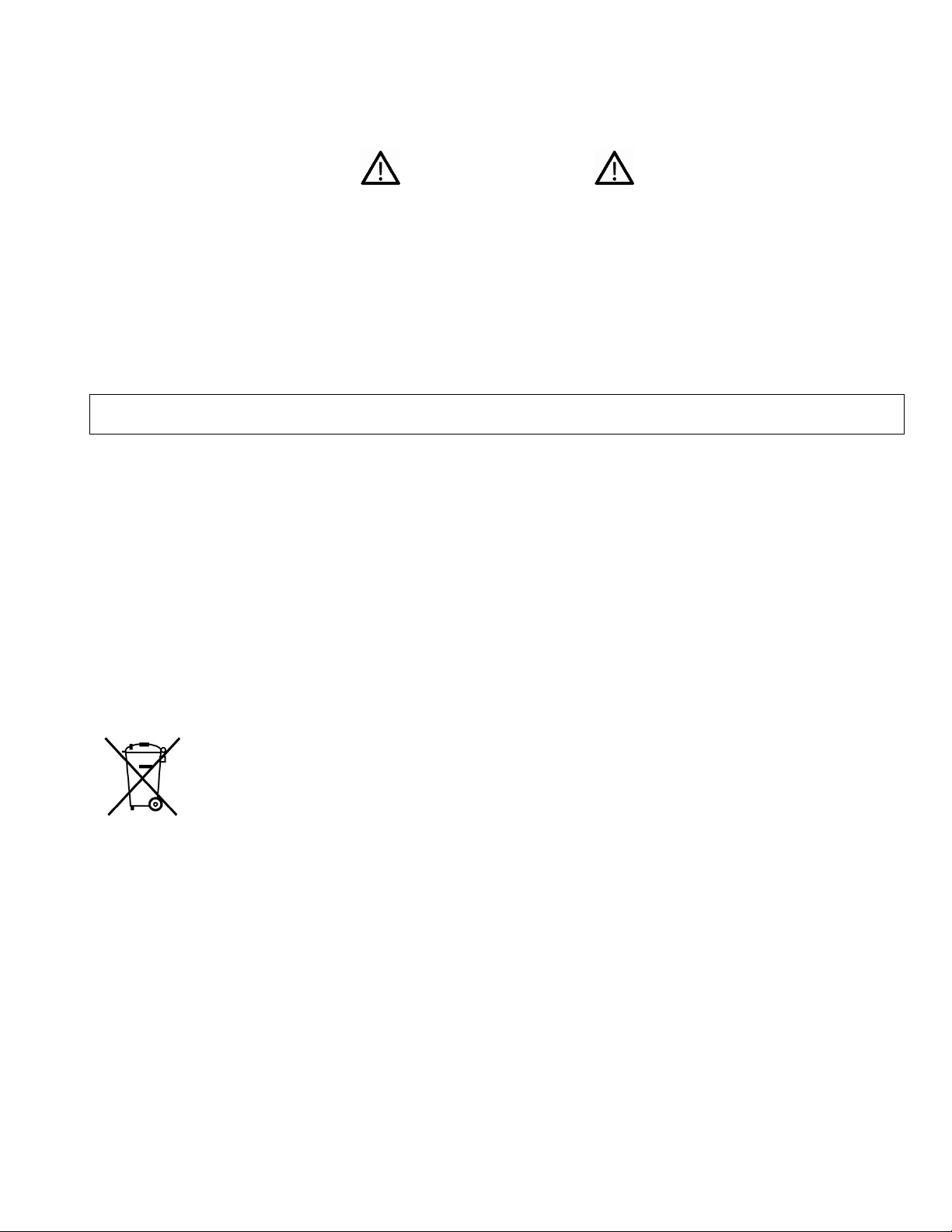
LED Visible
Control
Units
Readings
Audible
Light sensor
Alert LED
Gas Inlets
Filter
Sensor
Display
Sensor
Type
Status icons
IR communication
Alligator
Battery compartment
Front
Back
3. User Interface & Display Overview
The BW Solo has a single button for on/off, parameter viewing, and programming functions. The
display is backlit when you press the button.
Alarm
Beeper
Cover
Plate
Alarm Band
Button
Reference
Window
Port
Clip
10
Page 11

Honeywell BW Solo User Manual
3.1. Out-Of-Box Experience (First Time Use Only)
The first time the instrument is turned on, you are prompted to select a display language and to
enter time and date.
Note: Language selection during the first power-on is mandatory.
Note: If you do not press a button for 6 seconds during out-of-the-box power-on, the instrument
automatically turns off. Language selection during the first power-on is mandatory, although you
can skip the time and date. If a language was selected before this 6-second idle period, the
instrument shows the normal reading screen after the next start-up. If a language has not been
selected, then the next time the instrument is turned on, there is a prompt to select a language.
Press and hold the button for 3 seconds. When you power the unit on, it counts down, 3-2-1. LEDs
flash, the vibration alarm shakes, and the audible alarm sounds, and the Honeywell logo then
appears on the screen. After startup, the “Set language” screen is shown.
Step through the available languages by pressing the button. Once you see the language you want,
press and hold the button for 1 second.
Note: If you pass the language you want, press the button until your language is shown. Then
press and hold the button for 1 second.
Once you have set the language, wait 3 seconds, and the “Set time” screen is shown.
Press and hold the button for 1 second to set the time. Otherwise, press it once to change to “No.”
Then press the button for 1 second to advance to “Set date.” If you change your mind and want to
set the time, press the button once instead.
Set the hour (00 to 23) by pressing the button until you reach the correct hour. Once the hour is
selected, press and hold the button for 1 second.
When “Set minute” is shown, press the button repeatedly to reach the correct minute (00 through
59). Then press and hold the button for 1 second. The time is now set.
IMPORTANT!
If a major error that prevents the instrument from functioning is found during startup, an error
number is shown on the display. Shut off the instrument and restart it. If the error message is
shown again, shut off the instrument and contact Technical Services.
11
Page 12
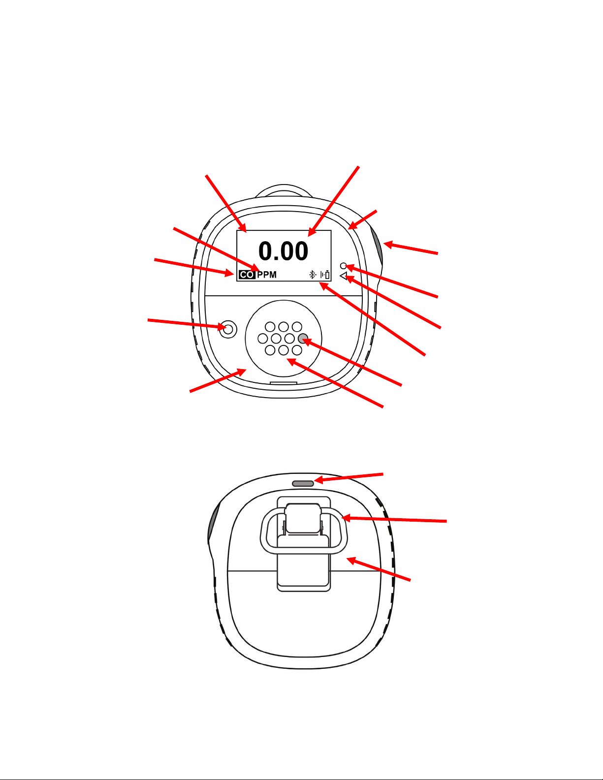
Honeywell BW Solo User Manual
Icon
Explanation
The battery icon is not shown on the display unless the remaining power is one day or
every second, and there are two beeps and two flashes every 30 seconds.
When less than 12 hours remains before a bump test should be performed, this icon is
use) to ensure proper sensor performance.
This icon is shown when there is less than 12 hours remaining before a calibration
When a sensor fails, has been removed, this icon is shown on the display, and there are
is one beep, one flash, and one vibration per second. The display shows “- - -“.
The Peak Reading icon is displayed when a peak gas reading has been detected in the
past 24 hours. The icon is otherwise hidden.
3.2. Status Indicator Icons
On-screen icons are used to indicate battery, bump, calibration and sensor status, as well as peak
reading. The table below details how and when each icon is displayed. The triangular red LED
located to the right of the screen illuminates to accompany these (it is active when the noncompliance feature is on).
less.
• When the battery’s remaining life falls below 24 hours, the battery icon is
shown and there is a flash and beep every 60 minutes.
• When the battery’s remaining life falls below 8 hours, the icon blinks on and off
shown and the buzzer sounds once every hour. When the user has also set the noncompliance option for the bump test reminder, the instrument flashes once and beeps
once every 10/30/60 seconds (the interval is set by the user, and this beep function
can be enabled/disabled).
The icon blinks once per second if there is a failed or skipped bump test, and the
instrument beeps three times every 60 minutes.
A bump test is required (and indicated by this icon) if:
• The defined period between bump tests has been exceeded (bump test overdue).
• The sensor has failed a previous bump test.
Failed bump test notification is shown on the screen if a bump test is failed. In the
information menu, it shows that the bump test must be performed “NOW.”
Note: the sensor should be challenged on a regular basis (before each day’s
should be performed. The instrument beeps once every 60 minutes.
The icon blinks once per second if there is a failed or skipped calibration, and the
instrument beeps three times every hour if the non-compliance option is off. When the
user has also set the non-compliance option for the calibration reminder, the
instrument flashes once and beeps once every 10/30/60 seconds (the interval is set by
the user, and this beep function can be enabled/disabled).
Calibration is required (and indicated by this icon) if:
• The defined period between calibrations has been exceeded.
• The sensor has failed a previous calibration.
4. BLE (Bluetooth Low Energy) Operation
12
Page 13

Honeywell BW Solo User Manual
Icon
Explanation
BLE connected. The icon is shown when data is being transferred.
BLE is off.
BLE is on, but is not connected.
Honeywell BW Solo is designed to operate via BLE (Bluetooth Low Energy) to send data to a
smartphone running Safety Communicator. The data can then be sent to computers running
Honeywell real-time monitoring software.
Note: If BLE operation is desired, the wireless option must be specified at time of ordering.
You can download Safety Communicator from the Google Play and iTunes store for free on one of
the supported phone platforms. However, you need a Honeywell real-time monitoring software
license to transmit monitor alarm information from Honeywell Real-Time Monitoring software.
4.1. BLE Icons
An icon is shown on the Honeywell BW Solo’s screen to show the status of BLE (Bluetooth Low
Energy), including connectivity.
4.2. Non-Compliance Indicator LEDs
The non-compliance indicator LEDs flash in the following situations:
• Low battery
• Low, High, TWA, STEL, or Negative alarm
• Failed self-diagnostic test
• Failed bump test or calibration
• Overdue bump test or calibration
When a functional error occurs, the gas detector tries to recover from it. If an error persists, contact
Honeywell Analytics or your distributor for technical assistance.
13
Page 14
Honeywell BW Solo User Manual
4.3. Pairing With Smartphones
Note: Bluetooth communication must be turned on in the Honeywell BW Solo instrument before
attempting to pair it with smartphones or other iOS or Android devices.
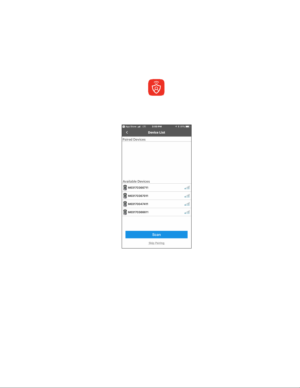
1. Open the Safety Communicator program.
2. The app opens and begins scanning for nearby Bluetooth instruments. As instruments are
found, they show up in the list. If the Honeywell BW Solo does not show up, click “Scan” so
that it searches for the instrument.
14
Page 15
Honeywell BW Solo User Manual
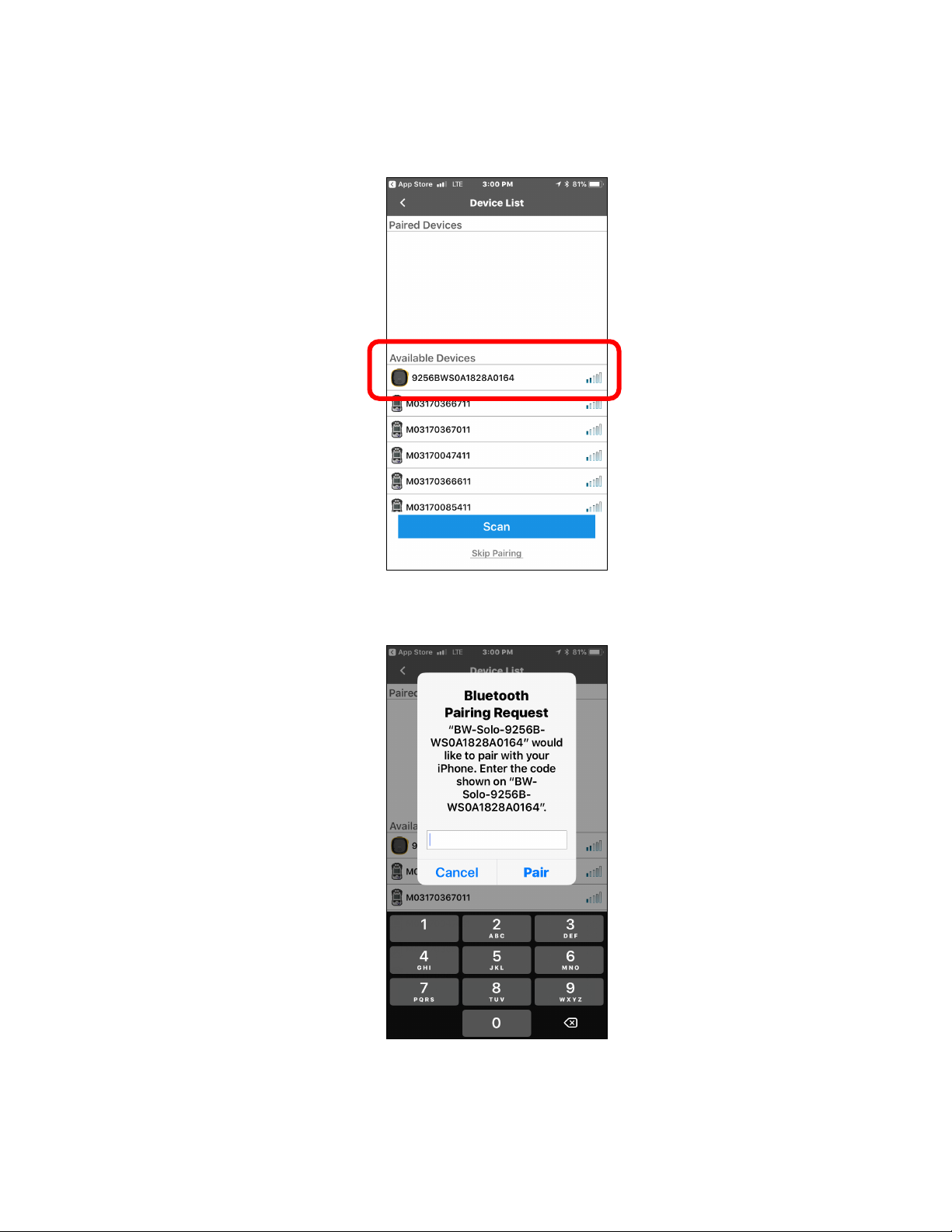
When the Honeywell BW Solo is found, it shows up in the list, represented by its image and
serial number:
3. Click on the Honeywell BW Solo device that displays the serial number of the unit you are
trying to connect. This message appears:
4. Look at the Honeywell BW Solo’s screen, and you will see a code number. Input that code
number into the field on your smartphone and then click “Pair.”
15
Page 16

Honeywell BW Solo User Manual
If it pairs successfully, a confirmation message is shown:
If you want to pair another instrument, click “Pair another.” Otherwise, click “Done.”
The Honeywell BW Solo is now sending data to Safety Communicator.
16
Page 17

Honeywell BW Solo User Manual
For further instructions, consult the Safety Communicator app. If you plan to use Honeywell realtime monitoring software, consult the relevant User Manual.
5. Battery
Always make sure the battery has enough power before using it. Only use this battery: 2/3AA 3.6V
1.65Ah Lithium battery (P/N: BWS-BAT01).
5.1. Battery Status
The battery icon is not shown on the display unless the remaining power is one day or less.
• When the battery’s remaining life falls below 24 hours, the battery icon is shown,
and there is a flash and beep every 60 minutes.
• When the battery’s remaining life falls below 8 hours, the icon blinks on and off every
second, and there are two beeps and two flashes every 30 seconds.
Note: To preserve the life of the battery, deactivate the instrument when it is not in use.
5.2. Battery Replacement
WARNING
To reduce the risk of ignition of hazardous atmospheres, remove or replace the battery only in an
area known to be non-hazardous!
CAUTION!
• Replace the battery in a safe area, free of hazardous gas, immediately when the detector enters
low battery alarm.
• Only use this battery: 2/3AA 3.6V 1.65Ah Lithium battery (P/N: BWS-BAT-01).
• Wear an ESD wrist or heel strap when replacing the battery. Avoid touching electronic
components or shorting circuits on the printed circuit board.
1. Flip up the alligator clip.
2. Remove the Phillips screw and lock washer.
3. Use the alligator clip to lift off the battery door.
17
Page 18

Honeywell BW Solo User Manual
4. Turn over the battery door, remove the old battery, and then press the new battery into place.
Note the polarity (+/- orientation).
5. Turn over the battery door and align the battery over its compartment. Then press it into the
instrument. Insert the screw and lock washer.
6. Tighten the screw. Do not overtighten the screw.
7. Turn on the instrument to make sure the battery was properly installed.
After a battery is inserted, the screen shows a blinking battery icon. The battery is being
conditioned (depassivation), and it typically takes about 30 seconds. If more time is required,
the blinking battery icon continues to be shown. When depassivation is complete, there is no
battery icon on the screen. The instrument can now be turned on.
IMPORTANT!
Used batteries must not be disposed of as general industrial or domestic waste. They should be
disposed of through suitable disposal facilities.
18
Page 19

Honeywell BW Solo User Manual
6. Turning The Honeywell BW Solo On & Off
6.1. Turning The Honeywell BW Solo On
With the instrument turned off, press and hold the button for 3 seconds. There is a 3-2-1
countdown, and then the audible alarm sounds and the display and LED alarm lights turn on and
off, plus the vibration alarm buzzes.
A Honeywell logo appears first, followed by a progress bar, and then the main reading display.
Note: The instrument checks for a critical low battery and will shut down if it is too low. It also
checks for forced bump or forced calibration if the function is enabled and if bump or calibration is
due.
6.2. Turning The Honeywell BW Solo Off
Note: You can only turn off the instrument from the main display screen.
Press and hold the button through the countdown. The unit will beep as the countdown progresses.
Then the message “Powering Down” is shown. Release the button. When the instrument is off, the
screen is dark.
6.3. Calibration Status
Note: When forced bump and calibration are enabled, the instrument will power down if it is not
bump tested or calibrated.
This icon is shown when less than 12 hours remains before a calibration should be
performed. The instrument flashes once and beeps once every 10/30/60 seconds, as set
by the user, when the user has also set the non-compliance option for the calibration
reminder. The beep can be enabled/disabled in the programming menu.
The icon blinks twice per second if there is a failed or skipped calibration, and the instrument beeps
three times every 60 seconds.
A calibration is required (and indicated by this icon) if:
• The defined period between calibrations has been exceeded (calibration overdue).
• The sensor has failed a previous calibration.
Failed calibration notification is shown on the screen if a calibration is failed. In the information
menu, it shows that the calibration must be performed “NOW.”
Note: The sensor should be challenged on a regular basis (before each day’s use) to ensure
proper sensor performance.
19
Page 20

Honeywell BW Solo User Manual
6.4. Bump Status
Note: When forced bump and calibration are enabled, the instrument will power down if it is not
bump tested or calibrated.
This icon is shown when less than 12 hours remains before a bump test should be
performed. The instrument flashes once and beeps once every 10/30/60 seconds, as set
by the user, when the user has also set the non-compliance option for the bump test
reminder.
The icon blinks twice per second if there is a failed or skipped bump test, and the instrument beeps
three times every 60 seconds.
A bump test is required (and indicated by this icon) if:
• The defined period between bump tests has been exceeded (calibration overdue).
• The sensor has failed a previous bump test.
Failed bump test notification is shown on the screen if a bump test is failed. In the information
menu, it shows that the calibration must be performed “NOW.”
Note: the sensor should be challenged on a regular basis (before each day’s use) to ensure proper
sensor performance.
6.5. Sensor Fault Status
When a sensor has been removed or failed, this icon is shown on the display, and there is one
flash, one beep, and a vibration alert every second. This display shows “- - -“.
20
Page 21

Honeywell BW Solo User Manual
Bump Test
Bump Test
Alert LED
7. Navigation
All navigation is done by pressing the single button on the Honeywell BW Solo. Here are the basic
“rules” of navigation on the instrument:
Power On 5-second hold (with 3-second countdown)
Power Off 5-second hold from the main screen
Enter menus (from main screen) Double-click
Move to next choice Single-click (quickly press once)
Select current choice
Hold until acknowledged Short Hold (press and hold for 1 second)
Cursor or current choice stops blinking
Cursor moves to next choice
Hold through countdown Long Hold (press and hold for 3 seconds)
Selected process is initiated
7.1. Glance Navigation
At the main screen, press the button once, and the backlight comes on. In addition, a critically low
battery level and any compliance issues are shown. For example, if the instrument fails a bump
test, it will show a Bump FAIL. If there is a failure, an associated icon and fault message alert you.
icon blinks
In addition, if there is a failure or low battery, the Alert LED will illuminate.
Note: When the last screen is reached, if you click the button once, it returns to the main screen. If
you do not click the button for 6 seconds from any of the screens, it returns to the main screen
automatically.
icon blinks
21
Page 22

Honeywell BW Solo User Manual
7.2. Main Navigation
1. Start at the main screen and click the button twice in rapid succession (similar to a double
mouse-click) to start.
2. The first option you see is “>Information”. Step through the other top-level options one click at
a time.
Note: A cursor (>) before a heading indicates that there are submenus or editable parameters
below the current screen.
22
Page 23

Honeywell BW Solo User Manual
8. Navigation: Information Menu
Basic navigation of the Honeywell BW Solo Information menu allows you to step through screens to
see settings and status. All are read-only information on a single screen, except for Event Log,
which has its own navigation to show one or more events.
1. Start at the main screen and click the button twice in rapid succession to start.
2. When you see “>Information,” hold the button for 1 second.
3. When the first screen, “Battery,” is shown, you can progress through the screens by clicking
the button once.
Note: When you reach the “Exit” screen, you can click once to cycle through the screens again, or
you can exit by holding the button for 1 second.
23
Page 24

Honeywell BW Solo User Manual
8.1. Event Log Navigation
Note: The Event Log is not present in the Information navigation for BW Solo monitors sold in North
America.
The Event Log consists of a listing of events that have been captured.
To enter the Event Log from the Information menu, hold the button down for 1 second at the “>Event Log”
prompt. There are three screens for each event, shown automatically in sequence from the date of the
event to the start of the event to the conclusion of the event. It also shows the reading and the type of
alarm (Low, High, etc.).
When there are multiple events in the Event Log, the screens cycle through a single event until you press
the button. Each time you press the button, the next event is shown. When all events have been shown,
the “<Exit” prompt is shown. To exit, hold the button for 1 second, and when the “>Event Log” prompt is
shown, click the button once to exit to the next screen in the Information sequence, Serial Number.
24
Page 25

Honeywell BW Solo User Manual
9. Navigation: Settings
The menu in Settings provides access to adjust settings. It has the following submenus:
• Language
• Time
• Date
• Units
• Readings
• Setpoints
• Latching
• Reminders
• Data Log*
• BLE (wireless versions only)*
• Assigned*
• Zone*
• IntelliFlash
• Non-compliance
• Passcode
• Exit
* Not included on the BW Solo Lite version. Also, the Mute function under Latching is not included
on the BW Solo Lite.
9.1. Enter Settings Mode
Note: A passcode can be required to access the settings menu. Setting an access restriction can
be done using the Passcode submenu or by using an IntelliDoX with SafetySuite software.
To enter Settings from the main reading screen:
• Press the button twice in rapid succession. You should see “>Information”.
• Press the button again, four times, to reach “>Settings”.
• Press and hold the button for 1 second. You should see “>Language”. This is the first editable
setting.
Note: If a passcode is required, input the 4-digit passcode (see section 9.17 for details). The
instrument does not have this feature enabled out of the box.
25
Page 26

Honeywell BW Solo User Manual
9.2. Menus & Submenus In Settings Mode
Each Settings menu has a submenu of editable settings. All are accessed, changed, and saved in
the same way:
1. Press the button once to step from one setting to the next.
2. When you find a setting to edit, hold the button for 1 second. The submenu for that setting is
shown.
3. Press the button once to step from one menu option to the next.
4. When you find the option you want to select, press and hold the button.
26
Page 27

Honeywell BW Solo User Manual
9.3. Language
English is the default language, but other languages can also be selected for the instrument. You
can select any of the languages for viewing onscreen information. Navigate to a language and
press the button for 1 second to select it.
Note: Language is initially set up during the out-of-the-box power-on sequence, but it can be
changed at any time.
9.4. Time
Time can be in 12- or 24-hour format. The default is 24-hour format.
• Changing the time format to 12-hour adds an indicator of AM or PM.
• Single digits have a “0” prefix (for example, 01:15, 02:30, etc.)
• Click to cycle through the digits
• Press the button for 1 second to select it.
9.5. Date
The date can be shown in these formats (the default is MM.DD.YYYY):
• DD.MM.YYYY (Day.Month.Year)
• MM.DD.YYYY (Month.Day.Year)
• YYYY.MM.DD (Year.Month.Day)
• Single digits have a “0” prefix (for example, 01, 02, etc.).
• When entering the year, it loops in a range from 2018 to 2099 before returning to 2080.
• Press the button for 1 second to select each digit.
9.6. Units
The units of measure can be set as either ppm (parts per million), mg/m3 (milligrams per cubic
meter), µmol/mol (micromoles per mole), or other units appropriate to the sensor in use.
9.7. Readings
Reset the TWA and STEL readings here. Also, enable/disable Peak reading reset and perform
action.
Note: The default value for the Peak reading is “disabled.” If it is enabled, there is an extra menu
option that allows resetting the peak reading. If it is disabled, this menu option is hidden.
27
Page 28

Honeywell BW Solo User Manual
9.8. Setpoints
In Setpoints, you can assign setpoints for low alarm, high alarm, TWA, and STEL.
• Range entry is assigned four digits and two decimal places.
• Range entry is limited between 0000.01 and 9999.99 (determined by gas type).
• Number entry loops through a cycle from 0 to 9 (the range entry limit determines the loop for
first digit entry and subsequent digits if the maximum is assigned).
• Press once to cycle through digits.
• Hold the button down for 1 second for confirmation to set each digit within the string.
9.9. Latching
The latch alarm option ensures that an alarm persists until it is acknowledged by the user.
If enabled, during an alarm condition the latched alarms option causes the low and high gas alarms
(audible, visible, and vibrator) to persist until the gas concentration is below the alarm setpoint and
the alarms have been acknowledged by pressing the button
You can turn latching on or off, and turn the mute option on or off. When the mute option is on,
there is no sound when an alarm is latched. When latching is on and mute is off, if the instrument is
still in a hazardous atmosphere, the real-time alarm will be displayed. When latching is on and mute
is off, and the instrument is in a safe atmosphere, gas type is displayed and the LED illuminated.
If the instrument is not in a hazardous atmosphere and you press the button to acknowledge, the
latching alarm shuts off.
Besides turning latching on and off, you can turn the alarm mute on or off. Note: If latching the
alarm is off, the option to “Mute” is hidden in the menu cycle.
The default setting for latching the alarm is off.
9.10. Reminders
Turn alert and force on or off, and set alert interval (in days) for bump and calibration.
Two separate menus are included for bump and calibration, and setting the interval. The “Interval”
duration is set as day, and the maximum interval is 365 days. Setting the “Interval” range to 000
days turns the “Alert” feature off and hides the “Interval” setting.
• Click to cycle through “Interval” digits.
• Press for 1 second to confirm and set each digit of the “Interval” string.
• Press and hold the button for 3 seconds to confirm and toggle all reminder alerts to “off.”
• Press the button for 1 second for all other toggle cycle interactions, including turning the
“Alert” reminder on.
9.10.1. Force On or Off for Bump/Cal
9.10.1.1.Force Cal
When this feature is enabled, the display reads “Cal Now.” The user cannot pass this screen
without calibration either manually or through IntelliDoX before proceeding to Idle Screen.
28
Page 29

Honeywell BW Solo User Manual
For Manual Calibration: At the “Cal Now” screen, press and hold the button to begin the process.
Follow the calibration instructions. Once the Calibration has passed, the user may proceed to the
idle screen. If calibration fails, then the instrument will revert to the “Cal Now” screen.
9.10.1.2.Force Bump
When this feature is enabled, the display reads “Bump Now.” The user cannot pass this screen
without bump testing either manually or through IntelliDoX before proceeding to Idle Screen.
For Manual Calibraion: Press and hold the button to start the bump process. Follow the
instructions for the bump process. Once the bump test has passed, the user may proceed to the
idle screen. If the bump test fails, then the instrument will revert to the “Bump Now” screen. If no
action is taken, then the unit will automatically shut off after 60 seconds.
The default setting for bump and calibration reminders is off.
9.11. Data Logging
Turn datalogging on or off and set the frequency interval (in seconds) for data collection.
Note: Turning data logging off hides the “Interval” setting option. The default setting for “Interval” is
005 seconds, and the interval can be set between 001 and 300 seconds.
The default setting for data logging is on.
9.12. BLE
On instruments that feature BLE (Bluetooth Low Energy), turn BLE communication on or off, so that
the instrument is discoverable or not discoverable.
Note: If BLE operation is desired, this option must be specified at time of order.
• When BLE is turned off, the BLE “off” icon is displayed.
• When BLE is turned on, the BLE “on” icon is displayed.
The default setting for BLE is on.
9.13. Assigned
The instrument can be assigned to a person, and their name can be programmed into it. You can
also turn assignment on or off, or edit/rename an assignment. The name can be up to 10
characters long.
The following are available for entry:
• Digits 0 to 9
• Upper-case characters A to Z
• A space
9.14. Zone
A zone’s name can be programmed. You can turn location on or off, and name, edit, or rename it.
The following are available for entry:
29
Page 30

Honeywell BW Solo User Manual
• Digits 0 to 9
• Upper-case characters A to Z
• A space
9.15. IntelliFlash
IntelliFlash verifies operation and compliance by flashing the green LED on the top of the instrument at
intervals you select. This indicator notifies you that the monitor has no fault conditions and that all
required maintenance, such as bump test and calibration, has been performed.
You can turn IntelliFlash on or off. You can also turn the “beep” on or off and set the flash interval as 10,
30, or 60 seconds.
The default setting for IntelliFlash is off. The default interval is 30 seconds.
9.16. Non-Compliance Indicator LEDs
Non-Compliance is a user-settable option that flashes the red Non-Compliance Indicator LEDs
around the perimeter when the instrument experiences the following.
• Gas Event
• Bump Due
• Calibration Due
Non-Compliance Indicator LEDs automatically come on, regardless of user configuration, for the
following.
• Sensor Fail
• Low Battery
• Calibration Fail
• Bump Fail
Non-Compliance Indicator LEDs are designed to alert other people around the user that their unit is
not in compliance. Users are also allowed to change the flash interval and initiate the audible
seconds (10, 30, or 60 seconds). You can turn this indicator on or off for gas events, bump due,
and calibration due. You can also turn “beep” on or off and set the interval (10, 30, or 60 seconds).
The default setting for the Non-Compliance feature is off. The default interval is 30 seconds.
1. Non-compliance events consist of Low, High, TWA, STEL, Negative, and Over Range status.
2. When a gas alarm is dismissed, non-compliance indication continues to indicate a gas event
(flash or flash and beep every 10, 30 or 60 seconds).
3. When a gas alarm is dismissed and if latching alarms is turned on, the instrument continues
to alert (audible, visible, and vibration, once or twice per second). After the button is pressed
to acknowledge the latching alarm, if “Gas Event” in non-compliance settings is on, the
instrument will continue to indicate a gas event.
4. Inserting the instrument in an IntelliDoX clears the non-compliance indication (for gas
events). Anytime the instrument is inserted in an IntelliDoX, the event log should be
recorded in the IntelliDoX. A manual bump test should clear the non-compliance indication
for both gas events and bump test due. Also, a manual calibration should clear both gas
events and calibration due.
30
Page 31

Honeywell BW Solo User Manual
9.17. Passcode
By default, no passcode is required for access to the instrument’s settings. However, a 4-digit
passcode can be set, which will prevent access to all settings. This can be set here or through
Honeywell SafetySuite software. If a passcode is ever lost and the instrument cannot be accessed,
contact Technical Support.
• Click once to advance the number (0, 1, 2, 3, etc.).
• Press and hold the button for 1 second to advance to the next digit.
• When the last digit is reached, press and hold the button for 1 second.
• Confirm by clicking the button once.
Important! If you forget your passcode, then contact Honeywell Technical Support.
9.18. Exit
Exit to the main menu
31
Page 32

Honeywell BW Solo User Manual
IMPORTANT! BUMP TEST THE MONITOR BEFORE EACH DAY’S USE
10. Zeroing
Because usage environments vary, there are many factors that may affect the performance of the
gas detector, including temperature and humidity changes as well as dust. If the ambient air is not
clean, gas readings might be inaccurate. For optimal performance, zero the gas detector once
every 24 hours or after changing of environmental conditions.
1. From the main reading screen, click the button twice in rapid succession to enter the menus.
2. Click the button until you see Zero.
3. Press and hold the button down for [verify this time, it is more than 1 sec] second. The
instrument counts down and then performs a zero calibration.
4. A progress bar indicates that the instrument is being zeroed.
• If the instrument passes zeroing, the message “Passed” appears.
• If the instrument fails zeroing, the message “Failed” appears.
If the instrument passed the zero calibration, it automatically reverts to the main reading screen
after 10 seconds.
11. Bump Testing
Prior to each day’s use, every gas detection monitor should be bump tested to confirm the response of all
sensors and activation of all alarms by exposing the monitor to a concentration of target gas that exceeds
the low alarm set point. A bump test is also recommended if the monitor has been subjected to physical
impact, liquid immersion, an Over Limit alarm event, or custody changes, or anytime the monitor’s
performance is in doubt.
To ensure greatest accuracy and safety, only bump test and calibrate in a fresh air environment.
The monitor should be calibrated every time it does not pass a bump test, but no less frequently than
every six months, depending on use and exposure to gas and contamination, and its operational mode.
• Calibration intervals and bump test procedures may vary due to national legislation.
• Honeywell recommends using calibration gas cylinders containing the gas that is appropriate to the
sensor you are using, and in the correct concentration.
1. From the main reading screen, click the button twice in rapid succession to enter the menus.
2. Click the button until you see Bump.
3. Press and hold the button down for 3 seconds. The instrument counts down and then
performs an AVV (audible, visible, vibration alarm) test, where it turns on three groups of red
LEDs, green LEDs, the buzzer, and vibration alarm, one at a time. The user can choose to
pass or fail after the test.
4. Press and hold the button to acknowledge the results. You should see “Apply Gas?”
5. Press the button to initiate the test.
32
Page 33

Honeywell BW Solo User Manual
6. Place the calibration cap over the Honeywell BW Solo, and hook the cap’s left clip to the
corresponding groove of the detector and press down on the tab to snap the right clip into
place.
7. If the hose is not connected to the calibration cap and the regulator on the calibration gas
cylinder, attach it now.
8. Open the cylinder valve by turning the pressure regulator knob counterclockwise.
9. Press and hold the button to initiate the bump test. A progress bar indicates that the bump
test is happening.
• If the instrument passes the bump test, the message “Passed” appears.
• If the instrument fails the bump test, the message “Failed” appears.
10. When “Turn Gas Off” appears, close the cylinder valve by turning the pressure regulator knob
clockwise.
11. Remove the calibration cap by pulling on the tab.
IMPORTANT!
If the sensor does not pass a bump test, repeat the bump test. If it fails repeated bump tests, perform a
full calibration. If it does not pass a full calibration, the sensor may need replacement. Do not use the
instrument until it passes a full calibration.
33
Page 34

Honeywell BW Solo User Manual
12. Calibrating
1. Enter Calibration mode. From the main reading screen, click the button twice in rapid
succession to enter the menus.
2. Click the button until you see Calibrate.
3. Place the calibration cap over the Honeywell BW Solo, and hook the cap’s left clip to the
corresponding groove of the detector and press down on the tab to snap the right clip into
place.
4. If the hose is not connected to the calibration cap and the regulator on the calibration gas
cylinder, attach it now.
5. Hold down the button for 3 seconds. When it enters span value screen, choose “yes” to
change the span value or choose “no” to skip and enter the zeroing process. It performs a
zero calibration.
6. When “Apply Gas” appears on the display, open the cylinder valve by turning the pressure
regulator knob counterclockwise.
7. Start the calibration by pressing and holding the button for 1 second. The calibration is
indicated by a progress bar, followed by “Passed” or “Failed.” You can abort the calibration by
clicking the button once.
IMPORTANT!
If it fails calibration, try calibrating again. If it cannot calibrate after repeated tries, the sensor
may need replacement or there may be a problem with the instrument. Do not use the
instrument until the issue is resolved.
8. When “Turn Gas Off” appears, close the cylinder valve by turning the pressure regulator knob
clockwise.
9. Remove the calibration cap by pulling on the tab.
34
Page 35

Honeywell BW Solo User Manual
Reference
Reference
Clean Filter
Dirty Filter
Sensor
Align tab
Insert tab
Press
Pop up
IMPORTANT!
If the sensor does not pass a full calibration, the sensor may need replacement. Do not use the
instrument until it passes a full calibration.
13. Replacing The Filter & Sensor
The sensor needs to be replaced when it is unable to be calibrated or behaves erratically. Also, the
filter should be inspected periodically, and it should be replaced if it shows signs of accumulated
dust, dirt, or debris.
13.1. Filter Color Reference
One of the holes in the sensor cover has a clear plastic window. While the other holes allow
ambient air (and dirt, debris, etc.) to reach the filter, the window keeps the part of the filter under it
clean. As a result, it is easy to visually confirm that the filter needs replacement by simply
comparing the clean spot with the other spots.
Window
Window
13.2. Removing The Cover
Remove the front cover by using the tab end of the calibration cap or a flat-blade screwdriver to pry
it upwards from the slot. This exposes the sensor with its filter attached.
With slot
In slot
Down
Cover
with filter
35
Page 36

Honeywell BW Solo User Manual
13.3. Replacing The Filter
If the filter appears dirty, replace it by peeling it off the sensor’s top surface. Peel a new sensor from
its protective paper and gently press it so it adheres evenly to the top perimeter of the sensor.
If the sensor does not need to be replaced, reinstall the cover.
Reinstall the front cover (see 13.5).
13.4. Replacing The Sensor
The sensor is held in place with a sensor frame and its four screws.
CAUTION!
1. Turn off the instrument before replacing the sensor.
2. Only change the sensor in a safe area, free of hazardous gas.
3. Wear an ESD wrist or heel strap when replacing the sensor. Avoid touching electronic
components on the detector printed circuit board or shorting circuits on the printed circuit
board.
4. Use only the sensor specifically designed for the Honeywell BW Solo. Otherwise, the detector
will not monitor the target gas.
5. Ensure that the sensor cover is properly aligned to ensure a proper environmental seal.
6. After replacing a sensor, allow the new sensor to stabilize the following amounts of time
before use:
30 minutes: CO, H
10 hours: CO-H, HCN
12 hours: O
Do not expose a sensor to vapors of organic solvents such as paint fumes or organic
solvents.
7. Always calibrate the instrument after changing the sensor.
2
S, CL2, H2, SO2, O3, PH3, NO2, ClO2, NH3
2
, ETO, NO
36
Page 37

Honeywell BW Solo User Manual
4-Series
1-Series
Jumper
Sensor
1. Remove the four screws holding the sensor frame in place.
2. Lift off the sensor frame and (if present) the rubber spacer.
3. Pull the sensor straight out. Note the three sockets on the pcb for the sensor’s electrodes for
the 4-Series sensor type and the three contact points for the 1-Series sensor type.
Sensor
4. Remove the old sensor by pressing it out of the sensor frame.
5. Dispose of the old sensor properly.
Keep the O-ring (1-Series), or sealing ring (4-Series Series) for reuse it when installing the
replacement sensor.
13.4.1. 4-Series Sensor Replacement
IMPORTANT!
Some 4-Series sensors are shipped with a jumper that connects two of the pins. This jumper
must be removed before installing the sensor. Turn the sensor upside-down, and slide the springtensioned jumper off of the sensor’s pins. Properly dispose of the jumper.
Sensor
1. If the sensor is a 4-Series type, align the electrodes with the sockets on the printed circuit
board and gently push it into place.
37
Page 38

Honeywell BW Solo User Manual
38
Page 39

Honeywell BW Solo User Manual
Sealing
Sensor
Metal
Top
Bottom
Jumper
Sensor
Jumper
Jumper
Jumper
Sensor
2. If not already done, place the metal insert inside the sealing ring, and then place that
combination over the sensor, followed by the sensor frame over the spacer. Align the frame
so that it fits properly around the audible alarm port. Tighten the screws to hold the frame in
place. Note: Do not overtighten.
Insert
Ring
Install a new filter over the sensor before replacing the cover.
Frame
13.4.2. 1-Series Sensor Replacement
IMPORTANT!
Some Series 1 sensors are shipped with a jumper that connects two of the pins. This jumper must
be removed before installing the sensor. Turn the sensor upside-down, and slide the jumper off of
the sensor’s pins. Properly dispose of the jumper.
View
View
Attached
Removed
39
Page 40

Honeywell BW Solo User Manual
1-Series
Rear
Notch
Sensor
Press in
O-ring
Invert the sensor so the three contacts are showing. Press the round part of the sensor into the
sensor frame, aligning its notch with the matching part of the sensor frame’s back. Invert the sensor
and stretch the O-ring around the perimeter of the sensor.
View
Sensor
Invert the sensor, and press the sensor all the way until it is fully seated in the sensor frame.
partway
Frame
Insert the sensor assembly into the instrument.
Tighten the screws to secure the assembly in place. Do not overtighten the screws.
Install a new filter over the sensor before replacing the cover.
40
Page 41

Honeywell BW Solo User Manual
13.5. Reinstalling The Cover
To reinstall the cover, align it over the compartment, press upper part into place first, and then
press the lower part until it clicks.
IMPORTANT!
Always calibrate the instrument after you replace the sensor. Failure to calibrate the instrument
can result in inaccurate readings. Some sensors require conditioning time before first use.
41
Page 42

Honeywell BW Solo User Manual
Infrared port
14. Maintenance
14.1. Cleaning
Occasional external cleaning of the instrument with a soft cloth is recommended. Do not use
detergents or chemicals. (You may use water or a water-based or non-alcoholic cleaner. Other
types of cleaners, solvents and lubricants can contaminate and cause permanent damage to the
sensor.) Do not submerge the instrument in liquid. It is a good idea to install the Calibration Adapter
before cleaning the housing, to keep dirt, dust, or moisture away from the sensor openings and to
keep the filter clean.
Note: If the Honeywell BW Solo is to be used with an IntelliDox, make sure the infrared (IR) sensor
on the rear of the instrument is clean to ensure best communication quality.
14.2. Replacing The Alligator Clip
If the alligator clip is damaged or loose, replace the combined alligator clip/battery door together.
14.3. Replacing/Servicing Other Parts
Many interior components, including the display, vibration alarm, and horn gasket, are replaceable,
but service should only be performed by qualified service personnel. Note: Attempting service may
void your warranty.
15. Firmware Update
Firmware can be updated using an IntelliDoX docking station with SafetySuite software. For more
information, refer to the IntelliDoX manual.
16. Year Of Manufacture
To identify the year and week of manufacture, refer to the four-digit marking adjacent to the serial
number on the instrument label. It follows this number format:
42
Page 43

Honeywell BW Solo User Manual
Gas
Type
Range
Resolution
Temperature
Low
Setpoint
High
Setpoint
H2S*
0-200 ppm
0.1
-40 to +60° C/-40 to 140°F
10 ppm
15 ppm
CO*
0-2000 ppm
1 ppm
-40 to +60° C/-40 to 140°F
35 ppm
200 ppm
O2*
0-30% v/v
0.1 %v/v
-40 to +60° C/-40 to 140°F
19.5 %v/v
23.5 %v/v
H2S
range)
0-500 ppm
0.1*
-40 to +50° C/-40 to 122°F
10 ppm
15 ppm
CO-H
0-2000 ppm
0.5 ppm
-30 to +50° C/-22 to 122°F
35 ppm
200 ppm
NH3
0-100
1 ppm
-20 to +40° C/-4 to 104°F
25 ppm
50 ppm
NH3
range)
0-400
1 ppm
-20 to +40° C/-4 to 104°F
25 ppm
50 ppm
SO2
0-100 ppm
0.1 ppm
-30 to +50° C/-22 to 122°F
2 ppm
5 ppm
HCN
0-100 ppm
0.1 ppm
-20 to +50° C/-4 to 122°F
4.7 ppm
10 ppm
Cl2
0-50 ppm
0.1 ppm
-20 to +40° C/-4 to 104°F
0.5 ppm
1.0 ppm
NO
0-250 ppm
0.2 ppm
-30 to +50° C/-22 to 122°F
25 ppm
25 ppm
NO2
0-100 ppm
0.1 ppm
-20 to +50° C/-4 to 122°F
2 ppm
5 ppm
PH3
0-5 ppm
0.1 ppm
-20 to +50° C/-4 to 122°F
0.3ppm
1.0 ppm
ETO
0-100 ppm
0.1 ppm
-30 to +50° C/-22 to 122°F
1 ppm
5 ppm
ClO2
0-1 ppm
0.01 ppm
-20 to +40° C/-4 to 104°F
0.10 ppm
0.30 ppm
O3
0-1 ppm
0.01 ppm
-30 to +50° C/-22 to 122°F
0.10 ppm
0.20 ppm
H2
0-1000 ppm
2 ppm
-20 to +50° C/-4 to 122°F
100 ppm
500 ppm
For example.: “9256 BWS 0A 18 30 00001” indicates that the instrument was manufactured in the
30th week of the year 2018.
17. Sensors & Settings
The available sensors and their range, resolution, temperature range, and low and high setpoints
are shown here:
(extended
(extended
* 1-Series sensor
43
Page 44

Honeywell BW Solo User Manual
Gas
Range
Resolution
Temperature
Low
High
H2S
0-100 ppm
0.1
-20 to +50° C/-4 to 122°F
10 ppm
15 ppm
CO
0-1000 ppm
1 ppm
-20 to +50° C/-4 to 140°F
35 ppm
200 ppm
O2
0-30% v/v
0.1 %v/v
-20 to +50° C/-4 to 140°F
19.5 %v/v
23.5 %v/v
H2S
range)
0-500 ppm
0.1*
-40 to +50° C/-40 to 122°F
10 ppm
15 ppm
CO-H
0-2000 ppm
0.5 ppm
-30 to +50° C/-22 to 122°F
35 ppm
200 ppm
NH3
0-100
1 ppm
-20 to +40° C/-4 to 104°F
25 ppm
50 ppm
NH3
range)
0-400
1 ppm
-20 to +40° C/-4 to 104°F
25 ppm
50 ppm
SO2
0-100 ppm
0.1 ppm
-30 to +50° C/-22 to 122°F
2 ppm
5 ppm
HCN
0-100 ppm
0.1 ppm
-20 to +50° C/-4 to 122°F
4.7 ppm
10 ppm
Cl2
0-50 ppm
0.1 ppm
-20 to +40° C/-4 to 104°F
0.5 ppm
1.0 ppm
NO
0-250 ppm
0.2 ppm
-30 to +50° C/-22 to 122°F
25 ppm
25 ppm
NO2
0-100 ppm
0.1 ppm
-20 to +50° C/-4 to 122°F
2 ppm
5 ppm
PH3
0-5 ppm
0.1 ppm
-20 to +50° C/-4 to 122°F
0.300 ppm
1.00 ppm
ETO
0-100 ppm
0.1 ppm
-30 to +50° C/-22 to 122°F
1 ppm
5 ppm
ClO2
0-1 ppm
0.01 ppm
-20 to +40° C/-4 to 104°F
0.10 ppm
0.30 ppm
O3
0-1 ppm
0.01 ppm
-30 to +50° C/-22 to 122°F
0.10 ppm
0.20 ppm
H2
0-1000 ppm
2 ppm
-20 to +50° C/-4 to 122°F
100 ppm
500 ppm
The following are available sensors for the Solo Lite (not available in North America):
Type
(extended
(extended
Setpoint
Setpoint
* 1-Series sensor
44
Page 45

Honeywell BW Solo User Manual
Problem
Possible Cause
Solution
The detector does not activate.
No battery.
Install a battery.
Depleted battery.
Replace the battery.
Damaged or defective detector.
Contact Technical Support.
Reversed battery.
Reinstall the battery correctly.
The detector enters alarm mode
Sensor needs to stabilize.
Used sensor: Wait 60 seconds.
New sensor: Wait 5 minutes.
Low battery alarm
Replace the battery.
Sensor alarm
Replace the sensor.
The start-up self-test fails during
one of the checks.
General fault
Contact Technical Support.
Alarm setpoints are incorrect.
Reset the alarm setpoints.
The detector does not display a
Target gas is present.
Detector is operating properly.
Use caution in suspect areas
Detector requires calibration
Calibrate the detector.
Sensor not stabilized
Used sensor: Wait 60 seconds.
New sensor: wait 5 minutes.
The detector does not respond to
Battery is depleted.
Replace the battery.
Detector is performing operations
Pushbutton operation restores
ends.
The detector does not accurately
Detector requires calibration.
Calibrate the sensor.
Detector is colder or hotter than
the ambient gas.
Allow the detector to acquire
ambient temperature before use.
Sensor filter is blocked
Clean the sensor filter.
The detector does not enter alarm
Incorrect setting of alarm
setpoint(s).
Reset the alarm setpoints.
Alarm setpoint(s) set to zero.
Reset the alarm setpoints.
Detector is in calibration mode.
Complete the calibration.
18. Troubleshooting
If a problem occurs, refer to the solutions provided here. If the problem persists, contact Technical
Support.
immediately when it is activated.
normal ambient gas reading after
the activation self-test.
the pushbutton.
measure the gas.
mode.
that do not require user input.
automatically when the operation
45
Page 46

Honeywell BW Solo User Manual
Size
2.74" H x 2.63" W x 1.42" D (69.7 x 66.7 x 36.1 mm) 1-Series sensor models
2.74" H x 2.63" W x 1.61" D (69.7 x 66.7 x 41 mm) 4-Series Series sensor models
Weight
3.56 oz. (101g) without Sensor/3.63~4.09 oz.(103~116g) with different sensors
Sensor
17 field-replaceable electrochemical sensors for toxics and oxygen
Battery Options
• ER14335 2/3AA lithium thionyl chloride battery (Over 1 year runtime)
Display
• FSTN dot matrix LCD display (128 x 64) with backlighting (activated
automatically with button press)
Display Readout
• Real-time reading of gas concentrations; battery status; wireless on/off.
• Various instrument status-related information
Control
1 button (single press, double press, short hold, long hold)
Sampling
Diffusion
Calibration
Automatic with IntelliDoX, or manual
Alarms
• Multi-tone audible (95 dB @ 30 cm/12”), vibration, visible (flashing bright red
• Real-time remote alarm notification (Wireless Model Only).
Datalogging
• Continuous datalogging (six months at 5 second intervals, running continuously)
• User-configurable datalogging interval (1 to 300 seconds)
Communication
Data Download
• Data download and instrument setup and upgrades on PC via IntelliDoX or BLE
• Wireless data and status transmission via built-in BLE (Wireless Model Only).
Wireless Network
BLE (Bluetooth Low Energy)
Wireless
Frequency
Bluetooth 2402~2480MHz
Wireless
FCC ID: SU3BWS1
RE-D Directive 2014/53/EU
Operating
Temperature
-40° to 140° F (-40° to 60° C)
Refer to specific measurement operating range of different sensors.
19. Honeywell BW Solo Specifications
and
Approvals
Specifications subject to change
LEDs), and on-screen indication of alarm conditions
(Wireless Model Only) or on cell phone via BLE (Wireless Model Only)
IC: 20969-BWS1
46
Page 47

Specifications
Humidity
5% to 95% relative humidity (non-condensing)
Refer to specific measurement operating range of different sensors
Dust and Water
Resistance
IP66; IP68 1.2 meters for 45 minutes
Certifications &
Class I, Division 1, Groups A,B,C,D T4;
CE Compliance
Conformity)
EMC directive: 2014/30/EU
ATEX directive: 2014/34/EU
FCC
Compliance
FCC Part 15
Languages
Chinese, Dutch, English, French, German, Italian, Japanese, Korean, Portuguese,
Russian, Spanish
Warranty
• 3 years for instruments equipped with 1-Series sensor
• 2 years on 4 Series sensors, except for 1 year for Cl2, ClO2, NH3, O3, ETO
continued
Honeywell BW Solo User Manual
Approvals
(European
Class I, Zone 0, AEx/Ex ia IIC T4 Ga -40°C≤ Tamb ≤ 60°C
ATEX: Sira 19ATEX2004
2460 II 1G I M1 / Ex ia IIC T4 Ga
Ex ia I Ma Tamb -40°C to 60°C
IECEx: IECEx SIR 19.0004 Ex ia IIC T4 Ga / Ex ia I Ma Tamb = -40°C to +60°C
FCC ID: SU38WS1
IC: 20969-BWS1
RED: RE-D Directive 2014/53/EU
For additional certifications, consult Honeywell Analytics.
RE directive: 2014/53/EU
2 years for instruments equipped with 4 Series sensor
• 3 years for CO, H2S, O2 1-Series sensors
Specifications subject to change
47
Page 48

Honeywell BW Solo User Manual
20. Limited Warranty and Limitation of Liability
Honeywell Analytics warrants the product to be free from defects in material and workmanship
under normal use and service over the operational life of the device. This warranty extends only to
the sale of new and unused products to the original buyer. Honeywell Analytics’ warranty obligation
is limited, at Honeywell Analytics’ option, to refund of the purchase price, repair or replacement of a
defective product that is returned to a Honeywell Analytics authorized service center within the
warranty period. In no event shall Honeywell Analytics’ liability hereunder exceed the purchase
price actually paid by the buyer for the Product.
This warranty does not include:
• fuses, disposable batteries or the routine replacement of parts due to the normal wear and
tear of the product arising from use;
• any product which in Honeywell Analytics’ opinion, has been misused, altered, neglected or
damaged, by accident or abnormal conditions of operation, handling or use;
• any damage or defects attributable to repair of the product by any person other than an
authorized dealer, or the installation of unapproved parts on the product.
The obligations set forth in this warranty are conditional on:
• proper storage, installation, calibration, use, maintenance and compliance with the product
manual instructions and any other applicable recommendations of Honeywell Analytics;
• the buyer promptly notifying Honeywell Analytics of any defect and, if required, promptly
making the product available for correction. No goods shall be returned to Honeywell
Analytics until receipt by the buyer of shipping instructions from Honeywell Analytics;
• the right of Honeywell Analytics to require that the buyer provide proof of purchase such as
the original invoice, bill of sale or packing slip to establish that the product is within the
warranty period.
THE BUYER AGREES THAT THIS WARRANTY IS THE BUYER’ S SOLE AND EXCLUSIVE
REMEDY AND IS IN LIEU OF ALL OTHER WARRANTIES, EXPRESS OR IMPLIED, INCLUDING
BUT NOT LIMITED TO ANY IMPLIED WARRANTY OF MERCHANTABILITY OR FITNESS FOR A
PARTICULAR PURPOSE. HONEYWELL ANALYTICS SHALL NOT BE LIABLE FOR ANY
SPECIAL, INDIRECT, INCIDENTAL, OR BASED ON CONTRACT, TORT OR RELIANCE OR ANY
OTHER THEORY.
48
Page 49

Europe, Middle East, Africa
Americas
Asia Pacific
For more information
www.honeywellanalytics.com
Life Safety Distribution GmbH
Tel: 00800 333 222 44 (Freephone number)
Tel: +41 44 943 4380 (Alternative number)
Fax: 00800 333 222 55
Middle East Tel: +971 4 450 5800
(Fixed Gas Detection)
Middle East Tel: +971 4 450 5852
(Portable Gas Detection)
gasdetection@honeywell.com
Honeywell Analytics
Distribution Inc.
Tel: +1 847 955 8200
Toll free: +1 800 538 0363
Fax: +1 847 955 8210
detectgas@honeywell.com
Honeywell Analytics Asia Pacific
Tel: +82 (0) 2 6909 0300
Fax: +82 (0) 2 2025 0328
India Tel: +91 124 4752700
analytics.ap@honeywell.com
Technical Services
EMEA: HAexpert@honeywell.com
US: ha.us.service@honeywell.com
AP: ha.ap.service@honeywell.com
G05-4001-000
Rev A October 2018
© 2019 Honeywell International
Honeywell Internal
 Loading...