

Page 1
AutoCube 8200
User Guide
User Guide
Page 2

Disclaimer
Honeywell International Inc. (“HII”) reserves the right to make changes in specifications and other information contained in
this document without prior notice, and the reader should in all cases consult HII to determine whether any such changes
have been made. The information in this publication does not represent a commitment on the part of HII.
HII shall not be liable for technical or editorial errors or omissions contained herein; nor for incidental or consequential
damages resulting from the furnishing, performance, or use of this material. HII disclaims all responsibility for the selection and use of software and/or hardware to achieve intended results.
This document contains proprietary information that is protected by copyright. All rights are reserved. No part of this document may be photocopied, reproduced, or translated into another language without the prior written consent of HII.
Copyright 2017-2018 Honeywell International Inc. All rights reserved.
Web Address:
Other product names or marks mentioned in this document may be trademarks or registered trademarks of other companies and are the property of their respective owners.
For patent information, refer to www.hsmpats.com.
www.honeywellaidc.com
Page 3

TABLE OF CONTENTS
Customer Support ..........................................................................................................................v
Technical Assistance ...............................................................................................................v
Product Service and Repair ..................................................................................................v
Limited Warranty ......................................................................................................................v
Chapter 1 - Getting Started............................................................................. 1
What is AutoCube 8200?............................................................................................................. 1
Out of the Box .................................................................................................................................. 1
Unpacking the Box Contents..................................................................................................... 1
About this Guide ............................................................................................................................. 2
Additional Documentation................................................................................................... 2
Software ............................................................................................................................................. 2
Chapter 2 - Assembly and Installation .........................................................3
Before You Begin ............................................................................................................................ 3
What You Need ................................................................................................................................ 3
Hardware Overview........................................................................................................................ 4
Installation Overview ....................................................................................................................5
Dimensions ................................................................................................................................ 5
Prepare the Mounting Surface .................................................................................................6
Adjust Stand Height...................................................................................................................... 6
Route the Cables ............................................................................................................................7
Install the AutoCube Camera ....................................................................................................8
Mount the Stand............................................................................................................................. 8
Install the Display (Optional)..................................................................................................10
Connect to the Host.............................................................................................................11
AutoCube 8200 User Guide i
Page 4

Connect a Scale (Optional)......................................................................................................12
Connect a Bar Code Scanner (Optional) ............................................................................12
Chapter 3 - Software Installation and Operation .................................... 13
Software Installation ..................................................................................................................13
Download the Software.......................................................................................................13
Install the Software............................................................................................................... 13
Launch the AutoCube Software.............................................................................................14
AutoCube Registration........................................................................................................14
Set Up the AutoCube Software ........................................................................................15
AutoCube Application Status ...........................................................................................16
Set Measurement Area........................................................................................................ 17
Operation ........................................................................................................................................19
Measure ....................................................................................................................................20
Manual Mode ...................................................................................................................20
Automatic Mode..............................................................................................................21
Measurement with a Bar Code Scanner................................................................21
Measurement Panel ......................................................................................................22
Recommendations.........................................................................................................23
Log ..............................................................................................................................................23
Settings .....................................................................................................................................24
Measurement Mode ......................................................................................................25
Wedge Settings................................................................................................................26
Dimension Display .........................................................................................................27
Unit of Measurement ....................................................................................................27
Export Mode .....................................................................................................................28
Troubleshoot.....................................................................................................................29
Log Settings & Image Location.................................................................................29
Export Text File ................................................................................................................30
Support Contact Information ....................................................................................31
Notification..............................................................................................................................31
Notification Popup Window........................................................................................32
About ..........................................................................................................................................33
Custom Applications ..................................................................................................................33
ii AutoCube 8200 User Guide
Page 5

Chapter 4 - Maintenance & Troubleshooting............................................35
Clean the Camera Lenses.........................................................................................................35
Troubleshooting............................................................................................................................35
Update the Software ...................................................................................................................36
Chapter 5 - Security........................................................................................39
System Architecture .............................................................................................................40
Security Checklists................................................................................................................41
Infection by Viruses and Other Malicious Software Agents...........................41
Unauthorized External Access...................................................................................41
Unauthorized Internal Access....................................................................................42
Audit Log...................................................................................................................................42
Appendix A - Technical Specifications........................................................43
AutoCube 8200 Technical Specifications ..........................................................................43
Label Placement...........................................................................................................................45
Laser Safety Label .......................................................................................................................45
Laser Aperture...............................................................................................................................45
Laser Output Angle...............................................................................................................46
AutoCube 8200 User Guide iii
Page 6

iv AutoCube 8200 User Guide
Page 7

Customer Support
Technical Assistance
To search our knowledge base for a solution or to log in to the Technical Support
portal and report a problem, go to www.hsmcontactsupport.com.
For our latest contact information, see www.honeywellaidc.com/locations.
Product Service and Repair
Honeywell International Inc. provides service for all of its products through service
centers throughout the world.
To obtain warranty or non-warranty service, you must first obtain a Return Material
Authorization number (RMA #), then return the product to Honeywell (postage
paid) with a copy of the dated purchase record.
To learn more, go to www.honeywellaidc.com and select Service & Repair at the
bottom of the page.
Limited Warranty
For warranty information, go to www.honeywellaidc.com and click Get Resources >
Warranty.
AutoCube 8200 User Guide v
Page 8

vi AutoCube 8200 User Guide
Page 9

CHAPTER
1
GETTING STARTED
What is AutoCube 8200?
AutoCube 8200 is a high performance fixed dimensioning system that uses 3D
depth sensing technology to measure objects. The dimensioning system consists
of the AutoCube camera mounted on a stand and connected to a host computing
system through a USB interface. It can be used in many different environments
from a courier company retail store to an inbound station of a warehouse.
Out of the Box
Make sure your shipping box contains these items (full kit):
• AutoCube camera with protective foam
• Stand with cable(s) and clamps
• 4 cable covers
•Stand clamp
• Display and holder (optional accessories)
• Mounting hardware
• Stand base cover
Unpacking the Box Contents
Carefully unpack the box contents.
Caution: Do not remove the protective foam from the camera during
installation.
AutoCube 8200 User Guide 1
Page 10

Caution: Do not open the AutoCube camera! The warranty and
certification is void if this stipulation is ignored. The device
may only be opened by authorized persons.
About this Guide
This guide provides assembling and mounting instructions as well as information
on system setup and configuration. It also includes maintenance instructions and
technical specifications.
Additional Documentation
This guide is intended to supplement the following documents available at
www.honeywellaidc.com:
• AutoCube 8200 Quick Start Guide
• AutoCube 8200 SDK and API
Software
The AutoCube software is available at hsmftp.honeywell.com. See Software
Installation on page 13 for details on downloading and installing.
2 AutoCube 8200 User Guide
Page 11

CHAPTER
2
ASSEMBLY AND INSTALLATION
Before You Begin
Determine where you will place the stand and if the cables will exit through the bottom of the stand (going through the mounting surface) or through the side of the
stand.
What You Need
• Drill with a Ø12.5 mm drill bit
•Measuring tape
• Allen wrench, 3 mm and 5 mm
• Adjustable Wrench
• Hole saw Ø32 mm (optional)
• Pliers (if cables exit side of stand)
• Phillips screw driver (optional)
AutoCube 8200 User Guide 3
Page 12
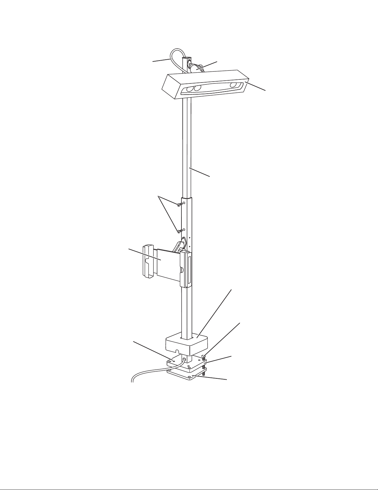
Hardware Overview
USB cable to
camera
Camera with
protective foam
Pole
Screws used to adjust
stand height (x4)
Display holder
(optional)
Stand cover
Mounting screws (x4)
Stand clamp
Stand base
USB cable(s)
to PC
Camera clamp
4 AutoCube 8200 User Guide
Note: The optional display can be mounted on any side of the pole.
Page 13
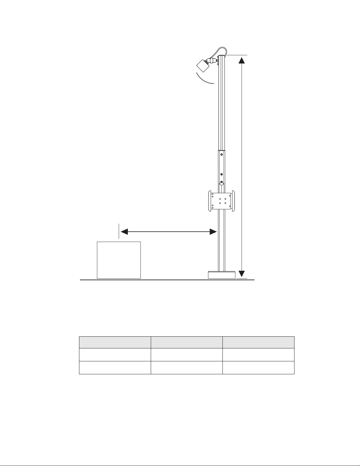
Installation Overview
A
D
H
Dimensions
The following are the recommended dimensions for installation. The camera angle
(A) and distance from the pole to the center of the measurement area (D) vary
depending on pole height (H).
Pole Height (H) Camera Angle (A) Distance (D)
≈160 cm / ≈5.25 ft ≈30° ≈63 cm / ≈2 ft
≈190 cm / ≈6.25 ft ≈45° ≈133 cm / ≈4.3 ft
Note: If you are not using the pole, the camera height (H), measured from the front center
of the camera, should be ≈1.5 m / ≈5 ft or ≈1.8 m / ≈ 6 ft.
AutoCube 8200 User Guide 5
Page 14
Prepare the Mounting Surface
Use the stand clamp as a template to trace and drill 4 holes (12 mm diameter) in
the mounting surface.
Note: If the cables will exit through the bottom of the pole and through the mounting
surface, you must also drill the center hole of the stand clamp large enough to pull
the cable(s) through.
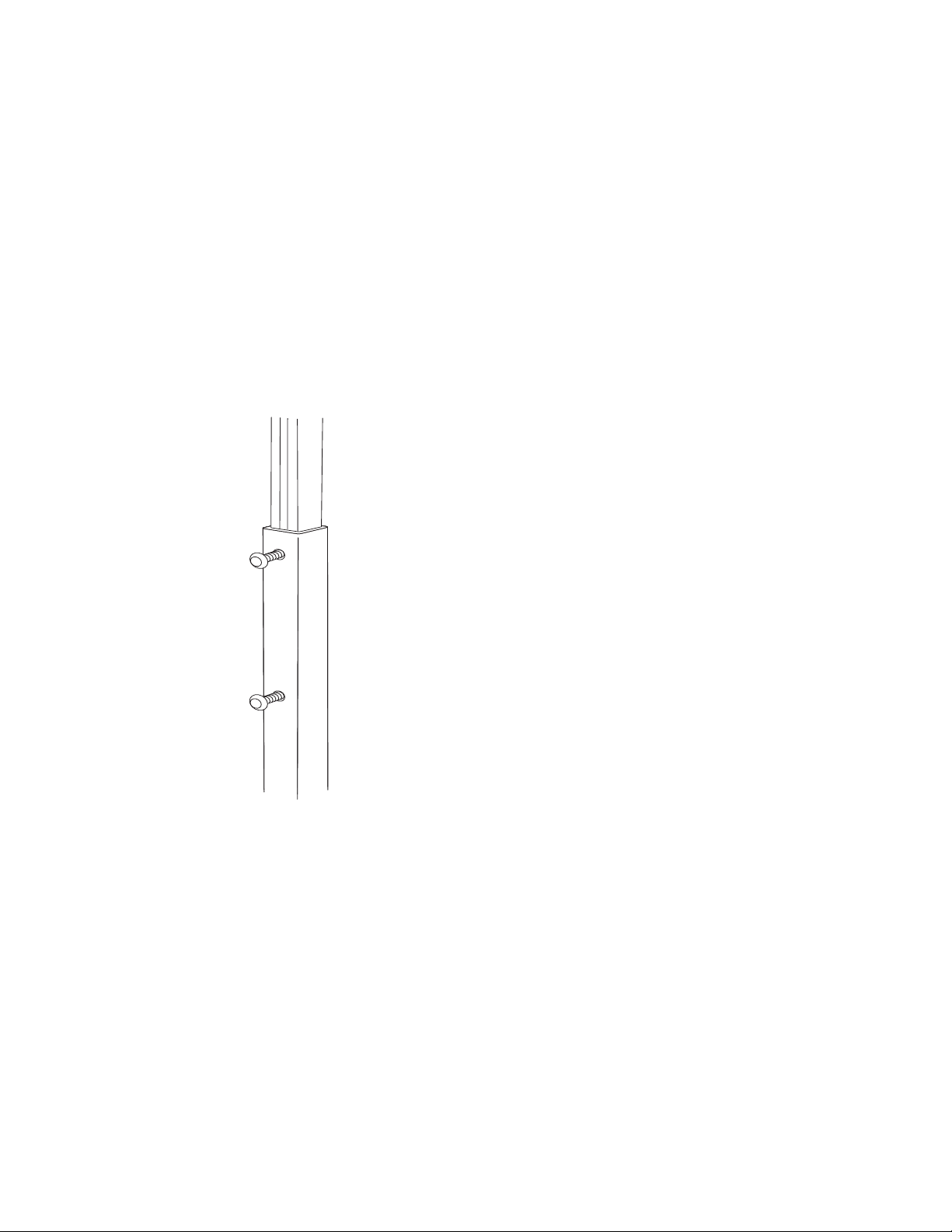
Adjust Stand Height
Stand height (H) is measured from the top of the stand to the top of the measurement area or scale.
1. Loosen the screws on each side of the pole (4x) using an Allen wrench.
2. Slide the pole up to the desired height. Refer to the recommended Dimensions.
3. Tighten screws on each side of the pole to secure the pole.
4. Pull the camera cable out of the bottom of the pole until approximately 25 cm
(10 in) remain exposed at the top of the pole so it can be attached to the camera
later.
6 AutoCube 8200 User Guide
Page 15
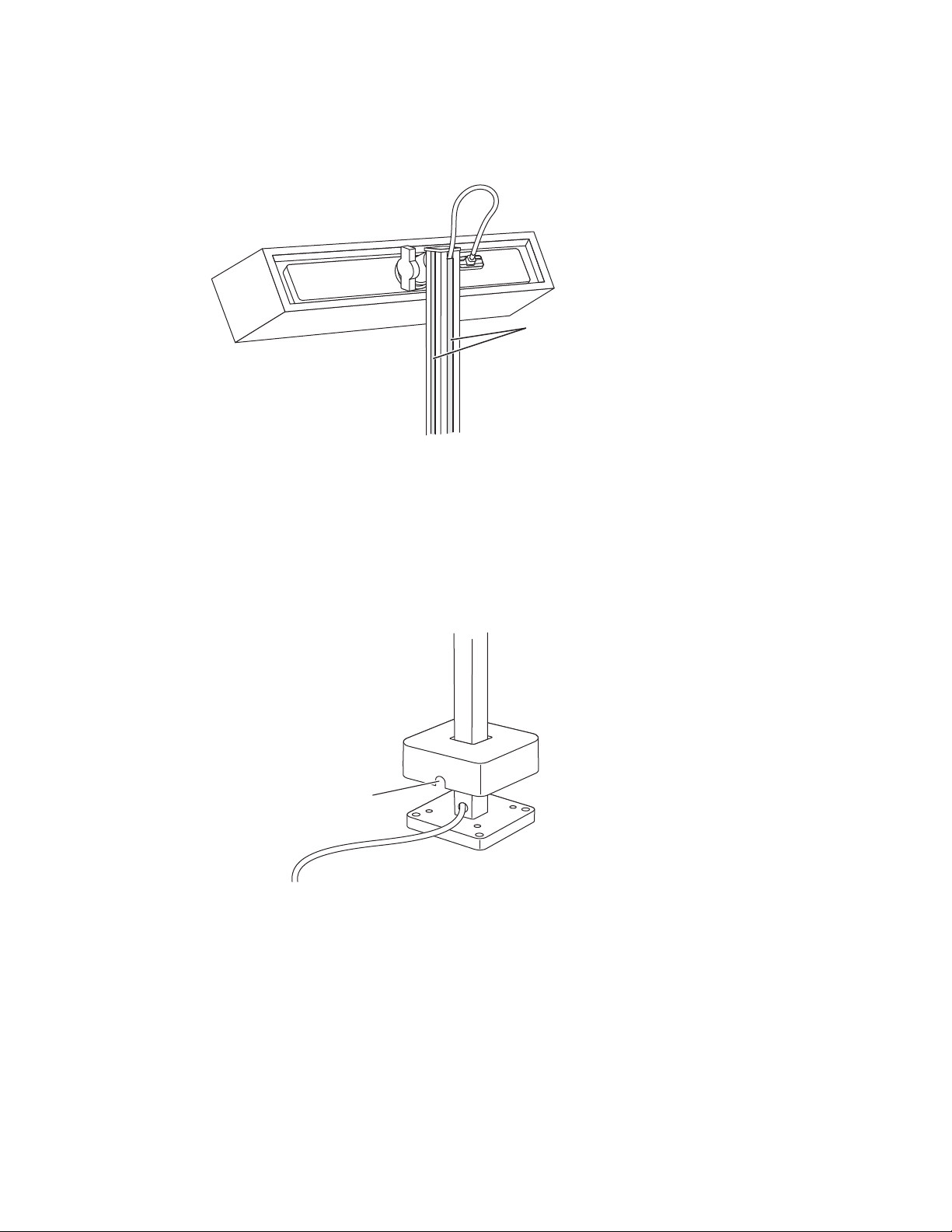
5. Cut the cable covers to the length needed to cover the cable channels on the
Cable covers
Cable exit
pole. Snap into cable channels.
Note: Cut the cable cover for the back side of the pole sightly shorter than the others so that
the camera cable can exit and be connected to the camera.
Route the Cables
By default the cables are routed out of the bottom of the stand. To route the cables
out of the side:
1. Pull up the stand cover - some resistance is normal.
2. Pull the cables up and through the side exit on the pole.
AutoCube 8200 User Guide 7
Page 16
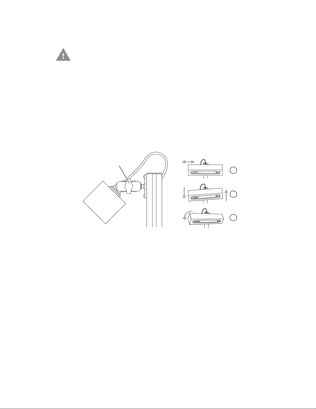
Install the AutoCube Camera
Knob to tighten
or loosen clamp
USB cable to
camera
Caution: Do not remove the protective foam during installation.
1. Angle the clamp on the top of the pole perpendicular to the pole. Turn the knob
to loosen the clamp.
2. Insert the ball of the camera into the clamp. Make sure the Honeywell logo on
the front is right side up. Adjust the camera to the correct angle (A) from the
pole (see Dimensions on page 5).
3. Turn the knob to tighten the clamp. Be sure it is tight enough so that the
camera will not move.
4. Attach the USB cable at the top of the pole to the camera. Secure the cable to
the camera by tightening the screws by hand.
Mount the Stand
8 AutoCube 8200 User Guide
Note: Be sure the camera is horizontal to the measurement area and aimed directly at the
area. No roll and no yaw.
Note: Keep the protective foam on the camera until installation is finished.
Recommended 2 person operation.
1. Rotate the stand assembly upright on the mounting surface. Align stand base
to previously drilled holes.
Note: If cables exit through the bottom of the pole, pull them through the mounting surface.
Page 17
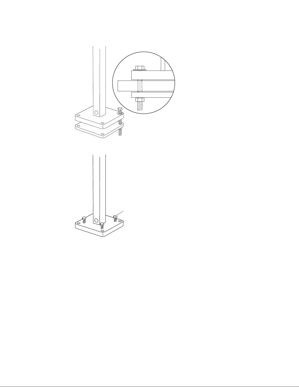
Place washers on the stand base then the mounting bolts through the stand
Leveling
screws (x4)
2.
base and mounting surface. Thread into the stand clamp placed under the
mounting surface.
3. Add the leveling screws if needed. Use in case the mounting surface is uneven.
The stand must be level
4. Pull the display cable (optional) out of the cable exit (side or bottom), leaving
enough for the cable to attach to the display (optional).
5. Slide the stand cover all the way down and click into place. Make sure cables
exit the side of the stand cover if using side exit.
6. Verify that the camera is level and at the correct angle. Adjust if necessary.
AutoCube 8200 User Guide 9
Page 18

Install the Display (Optional)
Knob to
tighten clamp
If using a display, you will need to install the display holder, then install the display.
You can mount the display holder on to any side of the pole.
Note: Depending on the kit, the display holder may already be installed on the pole. If that
is the case, skip the following instructions and go directly to the next section (To
install the display: on page 11).
To install the display holder:
1. Decide which side of the pole you want to mount the display holder. Remove the
cap plugs so that you have access to the screw holes.
2. Mount the RAM ball on to the pole using 2 screws (provided).
3. Attached the clamp to the RAM ball on the pole and to the RAM ball on the
display holder. Tighten using the knob on the side of the clamp.
4. Run the USB cable for the display through the hole on the side of the pole
(close to the display holder), exiting through the bottom or side of the pole
(depending on the installation).
10 AutoCube 8200 User Guide
Page 19

To install the display:
Note: Depending on your system, the driver for the display may need to be installed from
the CD provided with it.
1. Attach the USB cable to the display. Use the strain relief on the back of the display to hold the cable in position.
2. Pull open the side of the display holder, insert the display, then slide the open
side of the holder back into place over the display.
3. Secure the display by using 2 small screws (provided). On the back of the
holder, screw them into the holes located in the slots.
4. Adjust the position of the display by loosening the clamp with the knob. Set in
position and tighten the clamp. Remove the knob, conserving it for future use.
Connect to the Host
1. Connect the display cable(s) exiting the bottom or side of the stand to the host
PC USB port (s).
2. Turn on the host PC.
3. Carefully remove protective foam from the camera.
If using a display, it is detected by Windows as a second monitor. Set this monitor
as an extension of Windows desktop in Control Panel, Display, Change display
settings.
AutoCube 8200 User Guide 11
Page 20

Connect a Scale (Optional)
AutoCube supports flat top, ball top and roller top scales from the following vendors: Mettler Toledo, Fairbanks and Avery Weigh-Tronix. Scales must be connected
via USB HID interface.
Note: When using a ball top or roller top scale place a blank sheet of paper on the scale
before selecting the ground plane. Then remove the paper and continue with object
measurement.
Connect a Bar Code Scanner (Optional)
Honeywell bar code scanners connected with USB POS HID interface can be used
with AutoCube.
12 AutoCube 8200 User Guide
Page 21

CHAPTER
3
SOFTWARE INSTALLATION AND
OPERATION
Software Installation
The AutoCube software requires a 64-bit PC or laptop running Windows 7 or later.
Minimum required configuration is Dual Core i3 (or equivalent) desktop processor
with 2 GB RAM.
Download the Software
1. Go to hsmftp.honeywell.com.
2. Create an account if you have not already created one. If you have an account
sign in or click on Go to Site to sign in.
3. Install the Honeywell Download Manager tool before downloading the
software.
4. Locate the AutoCube software in the directory (Software/Dimensioning/
AutoCube).
Certification Software Version
NTEP 1.22.x.x
OIML/MID 1.52.x.x
No certification 1.12.x.x
5. Click Download. Download Manager will open and download the file.
Install the Software
Launch the installation by double clicking the .exe file. Follow the screen prompts.
During installation you will have the option to configure the AutoCube software to
launch at start up.
Note: You must have administrative rights on the PC to install the software.
AutoCube 8200 User Guide 13
Page 22

Launch the AutoCube Software
When you launch the AutoCube software the first time you must:
• Register your device
• Set up the AutoCube application
AutoCube Registration
Note: You must have administrative rights on the PC to complete the AutoCube
registration.
To complete AutoCube registration:
1. Launch the AutoCube software.
2. Click on Haven’t registered yet? Sign up and follow the screen prompts.
3. Enter your information in step 1. Enter the e-mail address that you want your ID
and password sent to. Click Next.
Caution: Enter a valid e-mail address so that you are sure to receive your
ID and password.
4. Enter your information in step 2, then click Register.
Caution: Enter a valid phone number so that you are sure to receive your
one time password (OTP).
Wait while registration is in progress. When finished, you will see the Registration Initiated screen. An e-mail is sent to your e-mail address.
5. Check your e-mail. Open the verification e-mail and click on Get Started Now
to confirm your e-mail address.
6. Your registration information opens in your browser. Make sure the information
is correct, click Proceed.
7. A one time password (OTP) is sent to your phone number. Enter your OTP and
click Submit OTP.
8. Click I Agree on the End User License Agreement screen and then click
Proceed.
9. Create a password for your account. The password must include at least one
lower case letter, one upper case letter, one number, and one special character.
Click Proceed.
10. Registration is complete. Close your browser.
14 AutoCube 8200 User Guide
Page 23

Set Up the AutoCube Software
To setup the AutoCube application
1. Launch the AutoCube application from the icon on your desktop or from the
Start menu (Start, AutoCube, AutoCube_App).
2. Click Sign in.
3. Enter your e-mail address and password then click Sign in.
Note: Uncheck the Remember me box if you are installing the application on a PC for non-
admin users. This will block non-admin users from being able to change the
application settings.
4. A one time password is sent to your phone. Enter your OTP. Click Submit OTP.
5. Return to the AutoCube application.
AutoCube 8200 User Guide 15
Page 24

6. To begin using the application with the default settings, select Standard
Settings then click Sign In.
To customize the application, select Custom Settings then click Sign In. Follow
the screen prompts to set up the following:
• Capture Mode and Length Axis (see page 25)
• Object Volume Display and Dimensional Weight Factor (see page 27)
• Unit of Measure (see page 27)
• Log Settings and Image Location (see page 29)
• Support Contact Information (see page 31)
These settings and additional options can be changed at any time using the Set-
tings menu (see page 24.)
Note: If the AutoCube device has already been registered, the button will display “Get
Started” instead of “Sign In.”
AutoCube Application Status
Once the AutoCube app is installed and running, you can see the status of the
app’s cloud connection in the lower left corner of the screen. If you have integrated
a scale, there will be a scale status shown as well.
Status Without Scale
Status With Scale
16 AutoCube 8200 User Guide
Page 25

There are 3 possible statuses:
• Connecting - in the process of connecting.
• Connected - connected and ready to be used.
• Disconnected - not connected. If the Cloud status is disconnected, you can
continue to use the app for up to 14 days, but you will not be able to send or
receive information from the cloud (such as software updates). If you are using
a scale and the Scale status is disconnected, you can continue to use the app,
but it will not receive information from the scale.
Set Measurement Area
The measurement area can be a counter top or an object such as a scale.
1. Click on the image to select the area. If you are using a scale or other type of
platform, place it in the image and click on it.
Select Measurement Area: Counter Top
AutoCube 8200 User Guide 17
Page 26

Select Measurement Area: Scale
*
Note: Make sure that there are no other objects in the view of the camera when setting the
measurement area.
2. Wait a few seconds then a colored area appears showing the area selected.
Click accept to continue or clear to start over again.
Measurement Area Set: Counter Top
18 AutoCube 8200 User Guide
Page 27

Operation
Measurement Area Set: Scale
To navigate in the AutoCube software, use the menus on the top of the application:
• Measure
• Log
• Settings
• Notification
• About
AutoCube 8200 User Guide 19
Page 28

Measure
Note: The Weight field will only display if you are using a connected scale. Please refer to
Manual Mode
Depending on how your application is setup, AutoCube can operate in two modes:
• Manual Mode
•Automatic Mode
the section Measurement Panel on page 22.
Place the package in the measurement area. (In the example below, a scale is not
connected so the Weight field is not displayed.):
Click the Measure button to measure it.
20 AutoCube 8200 User Guide
Page 29

Automatic Mode
Place the package in the measurement area and it is measured automatically. If a
scale is attached it will be weighed as well, as shown in the example below:
Measurement with a Bar Code Scanner
When a bar code scanner is connected via USB to your computer, the Scan Data
field will display in the measurement panel. No other software should have an
active bar code scanner connection while you are using the AutoCube app.
You have two options for capturing scan data:
• Scan a bar code to initiate the AutoCube measurement process.
Or
•Click Measure then scan the bar code.
Note: Glare from the bar code scanner may affect the image but will not affect the
dimensioning.
AutoCube 8200 User Guide 21
Page 30

.
Measurement
Panel - No Scale
Connected
Measurement
Panel - Scale
Connected
Measurement
Panel - Scale and
Scanner
Connected
Note: The bar code displayed in the Scan Data field may be cropped but the bar code data
will be captured in full.
Measurement Panel
The information in the measurement panel varies depending on how the software
is set up and whether you have connected a scale. Volume and Dimensional
Weight are optional and selected in the settings (see Dimension Display on page
27).
Note: Volume and Dimensional Weight outputs are for information only and are not
certified measurements.
22 AutoCube 8200 User Guide
Note: The measurement panel can display up to 7 data points. If more than 7 data points
are needed, volume will not display in the measurement panel.
Page 31

Recommendations
• Packages need to be placed at least partially within the measurement area (see
• Packages need to be placed fully on the platform in the camera’s view. If not, an
• Black, shiny, and transparent packages are not supported.
• The following irregular shapes are supported:
Note: Tubes (cylinders and prisms) should not be orientated vertically.
• Stacked packages will be measured as one object.
• Can be used in typical office lighting, avoid direct sunlight. Light source must
Set Measurement Area on page 17).
error message will appear:
•Tube
• Triangular tube (prism)
• Cubes with an uneven top, sloped top, uneven side
not be directed toward the camera optics.
Log
All actions by the camera are recorded in the log and categorized as:
• Measurement—measurement information such as length, width and height. If a
scale is connected, weight will be shown as well.
• Info—system information such as ground plane set, system initialized, etc.
• Errors—system errors such as invalid measurement, out of range, etc.
AutoCube 8200 User Guide 23
Page 32

Note: An asterisk in the Message field indicates that the dimensions are not for legal trade.
Note: If you uninstall and reinstall the AutoCube software, the log and images are kept and
Settings
By default the list is sorted by Log ID. You can also choose to sort the list by Event
by clicking on Event.
When a measurement is recorded, the measured image with wire frame is also
saved. To access the image, click on the small blue box on the right.
are not overwritten.
To view or edit the AutoCube application settings:
1. Click on the Settings menu.
24 AutoCube 8200 User Guide
Page 33

2. Use the menu on the left to access the different settings.
Note: The Settings menu may be slightly different depending on your region.
Measurement Mode
Select Automatic or Manual Capture Mode and Length Axis.
You can also use this screen to enable the Wireframe feature, which adds a yellow
outline to measured objects as shown below. By default the Wireframe option is
turned off.
AutoCube 8200 User Guide 25
Page 34

Wedge Settings
Note: The wedge function is only available in manual measurement mode.
The wedge function is used to send measurement data to an active application
(such as Notepad) by using a keyboard shortcut.
Set up the following options:
• Enable Wedge turns the Wedge function on.
•Use Data Transfer Hot Key to create a keyboard shortcut that will be used to
send the data to the open application.
•Use the Define Data Points and Delimiter field to specify which data is
transmitted and in what order. Use delimiters as separators between data
points. Available data points and delimiters are bar code, length, width, height,
weight, volume, dimension unit, weight unit, date and time, horizontal tab,
vertical tab, space, comma, and carriage return.
• Select Round up to next integer if you prefer dimension (or weight, if a scale is
in use) to round up rather than be sent as a fraction. For example, if this field is
turned on for dimensions, a length of 2.5 inches would be transmitted as 3
inches.
To send measurement data using the Wedge function:
1. Measure an object (see Measure on page 20).
2. Once the measurements are taken and shown in the measurement panel, open
an application such as Notepad.
3. Press the Data Transfer Hot Key combination that you have selected in the
wedge settings.
4. The data is transferred to the open application.
26 AutoCube 8200 User Guide
Page 35

Dimension Display
Select additional information that will be displayed in the Measurement Panel
when measuring an object.
Note: Volume and Dimensional Weight outputs are for information only and are not
certified measurements.
Note: Click on the question mark for an explanation of Dimensional Weight Factor.
Unit of Measurement
Depending on your region you may or may not be able to select a different unit of
measurement.
AutoCube 8200 User Guide 27
Page 36

Export Mode
Screen Image Raw Image
(everything in the camera’s
field of view)
Cropped Image
If you are using a custom application, you can choose to export information manually (see Custom Applications on page 33) or automatically by selecting an Export
Mode.
You also have the option to save the image (see the next section Types of Saved
Images) as well as limiting the number of saved images. The image will be saved in
the same location as the image with measurements. See Log Settings & Image
Location on page 29 to set storage location.
Types of Saved Images
28 AutoCube 8200 User Guide
Page 37

Troubleshoot
Enable or disable the troubleshoot log. You can also select what information you
want to be included in the log: Info, error, and/or warning.
The troubleshoot log is located in C:\Program data\AutoCubeLogs. This log may
be used by technical support.
Log Settings & Image Location
• Select the number of log records to store. The required minimum of log records
is 1000.
Note: An increased number of logs saved will increase the amount of space used on the
hard drive.
•If you enable Image Capture Without Dimensioning an additional Capture
Image button will display on the Measure screen. This option allows you to use
AutoCube as a camera without taking measurements.
AutoCube 8200 User Guide 29
Page 38

Export Text File
• Specify an image storage location. This location should be accessible by both
admin and non-admin users.
• You have the option to save an image with bar code data in the file name. In the
example below, the bar code data is displayed in the file name at the top and in
the Scan Data field on the right:
This setting is used to automatically export data to a text file.
• Enable Text File Export turns the setting on.
• Specify where you would like the text file to be saved in the Text File Storage
Location field. This location should be accessible by both admin and nonadmin users.
•Use the Data to be Exported field to specify which data is transmitted and in
what order. Use delimiters as separators between data points. Available data
points and delimiters are bar code, length, width, height, weight, volume,
dimension unit, weight unit, date and time, horizontal tab, vertical tab, space,
comma, carriage return, and image name.
30 AutoCube 8200 User Guide
Page 39

• If you have already started a text file and you change the data points, going
forward the data exported to that existing file will follow the new parameters. If
you want to start a new text file, click Start New File.
Support Contact Information
Record support contact information here for easy access.
Notification
To display the list of all notifications (completed and pending), click on the Notification menu. This list shows the type of update, status, and how many times it has
been postponed (snoozed).
AutoCube 8200 User Guide 31
Page 40

From this list you can install or snooze pending updates using the snooze icon .
You can also delete completed updates using the delete icon .
Note: Non-admin users do not have access to the snooze icon .
Notification Popup Window
When an update is pushed out to a device, a notification popup window appears.
Choose an action from the Action drop down list. You can select Install now or
postpone the update. Click Done when you are finished.
You have 15 minutes to respond to the notification. If you do not respond, the
update will start automatically after 15 minutes.
For more information on software updates, see Update the Software on page 36.
Note: If you are not the administrator, you can only select snooze 3 days in the drop down
list. This gives the non-admin user time to inform the administrator of the notification
so they can connect with administrator privileges and install the update.
Note: The notifications popup window only shows the pending updates.
32 AutoCube 8200 User Guide
Page 41

About
The About screen shows information specific to your device.
Custom Applications
The AutoCube software can also be integrated into a custom application using the
AutoCube SDK and API. When using a custom application with the AutoCube application, you will be able to export the AutoCube application information to the custom application using the Export button.
For more information go to www.honeywellaidc.com for the AutoCube SDK documentation.
AutoCube 8200 User Guide 33
Page 42

34 AutoCube 8200 User Guide
Page 43

CHAPTER
4
MAINTENANCE &
TROUBLESHOOTING
Clean the Camera Lenses
Depending on the environment, the AutoCube camera lenses can become dirty
with dust and/or grease. To clean the lenses use compressed air to blow off dust
and debris. If more cleaning is necessary use isopropyl alcohol (or similar solution)
applied with an optical grade cleaning cloth.
Troubleshooting
Problem Solution
Image is frozen in AutoCube
application.
Cannot detect object.
Cannot set measurement area.
Must reset measurement area
when re-launching the
application.
Forgot your AutoCube account
ID and password.
Application gets stuck then
does not recognize the
connected device.
App status shows disconnected. The app is not able to connect to the cloud. Check your
Close the application, unplug and re-plug the USB cable
for the camera, then restart the AutoCube application.
• Object is too dark.
• Object is too shiny.
• Object is too big.
• Object is not in the measurement area.
• Object is transparent
• Ground plane surface is too reflective or transparent.
• Ground place surface is not flat enough.
Be sure that the measurement area is empty when
launching the application.
Click on “Forgot your password?” or “Can’t access your
account?” on the AutoCube Registration login page.
Follow the instructions.
Close the application, unplug and re-plug the camera,
then restart if the software. If this continues, restart the
PC.
Internet connection.
AutoCube 8200 User Guide 35
Page 44

Problem Solution
In Windows 10, when a bar code
scanner is connected the
application does not show scan
data.
During software update
notification, PC Admin is not
able to see the clock icon to
select snooze or install.
“Dimensioning disabled. Please
use consistent measurement
unit on weight scale and
dimensioning.”
AutoCube app becomes
unresponsive while laptop is in
sleep mode.
Update the Software
To update the software from the notification popup window
When a software update is available, the notification popup window appears.
1. Click on the Action drop down list to choose an action.
Install null driver to allow Honeywell scanners to work in
USB HID interface for Windows 10. Refer to
docs.microsoft.com for more information on installing a
null driver.
AutoCube application must be run as administrator in
Windows 8, 8.1 and 10.
If the scale uses metric weights, set the unit of measure
in AutoCube to centimeters. If the scale measures in
pounds, set AutoCube to use inches.
Restart application and turn off sleep or hibernation
mode.
2. Select Install now to launch the software update. Click Done.
You can also choose to postpone (snooze) the update. If the update has been
postponed, you can launch it from the Notification menu. See To update the
software from the Notification menu on page 37.
You can only postpone an update for up to 5 times. After that, you will simply be
notified when the update starts.
3. The software download and installation begin. Follow the screen prompts.
36 AutoCube 8200 User Guide
Page 45

When the download and installation are complete, the application closes automatically. You will receive a message indicating that the operation was successful.
4. Restart the application and continue working. If the software upgrade fails, you
will receive a notification. In this case, continue working with the current
software version.
To update the software from the Notification menu
If a software update has been snoozed, you must launch the update from the Notification Menu.
1. Click on the Notification menu.
AutoCube 8200 User Guide 37
Page 46

2. Click on the snooze icon .
3. Select Install now, then click Done (you can also postpone (snooze) the update
on this screen).
4. The software download and installation begin. Follow the screen prompts.
When the download and installation are complete, the application closes automatically. You will receive a message indicating that the operation was successful.
5. Restart the application and continue working.
If the software upgrade fails, you will receive a notification. In this case, continue working with the current software version.
38 AutoCube 8200 User Guide
Page 47

CHAPTER
5
SECURITY
This section defines the security processes, both implemented and recommended by Honeywell, for using the AutoCube fixed dimensioning system.
AutoCube 8200 User Guide 39
Page 48

System Architecture
AutoCube In-Premise Architechture
Honeywell Cloud
Services
TLS
Cloud
TLS
TLS
USB
AutoCube Camera
Customer Firewall
Host Computer
40 AutoCube 8200 User Guide
Page 49

Security Checklists
The checklists cover some of the main threats that may exist on a network containing AutoCube and the steps that can be used to mitigate them.
Note: Honeywell recommends that the PC on which the AutoCube software is installed is
protected with a full disk encryption solution such as Microsoft’s BitLocker or other
equivalent solution.
Infection by Viruses and Other Malicious Software Agents
This threat encompasses malicious software agents such as viruses, spy-ware
(Trojans), and worms.
The intrusion of malicious software agents can result in:
• Performance degradation.
• Loss of system availability.
• The capture, modification, or deletion of data.
Mitigation Steps
Steps
Ensure that your virus protection and Microsoft security hot fixes are up to date on all computers
where AutoCube software is installed and AutoCube system is connected to it.
Ensure that there is no email or instant messaging clients on any computer hosting AutoCube
system.
Note: Note: The use of spy-ware removal applications may cause unexpected results if run
on your computers hosting AutoCube system. These applications may alter registry
settings that are crucial to the operation of the software.
Unauthorized External Access
This threat includes intrusion into the AutoCube system from the business network
and possibly an intranet or the Internet.
Unauthorized external access can result in:
• Loss of system availability.
• Incorrect execution of controls causing the failure of search and rescue.
• Theft or damage of system contents.
• The capture, modification, or deletion of data.
Damage to reputation if the external access becomes public knowledge.
AutoCube 8200 User Guide 41
Page 50

Mitigation Steps
Steps
Set the minimum level of privilege for all accounts, and enforce a strong password policy, both for
Windows user accounts and AutoCube user accounts.
Restrict access to the AutoCube system to authorized user only.
Use a firewall at the interface between other networks and AutoCube devices.
Unauthorized Internal Access
This threat encompasses unauthorized access from people or systems within the
business network. This threat is the most difficult to counter since attackers may
have legitimate access to part of the system and are simply trying to exceed their
permitted access.
Unauthorized internal access can result in:
• Loss of system availability.
• Incorrect execution of controls causing the failure of the AutoCube system.
• Incorrect execution of controls causing the failure of search and rescue.
• The capture, modification, or deletion of data.
Theft or damage of system contents.
Audit Log
Mitigation Steps
Steps
Ensure AutoCube software security.
Do not allow the use of unauthorized removable media (for example, DVDs or memory sticks) on any
computer connected to AutoCube system.
Use strong passwords on network equipment.
Use and enforce a strong password policy.
All captured data (measurements), events and errors are stored into the Log (see
Log on page 23). The log serves as product history for Weight and Measure certifi-
cation audit on customer site. It is read-only for all users including system administrators of the computer. Content of the log is protected from modifications using
a software protection algorithm.
The log can stored up to 10K entries. When storage capacity is reached, the oldest
entry is replaced by the new one.
42 AutoCube 8200 User Guide
Page 51

APPENDIX
A
TECHNICAL SPECIFICATIONS
AutoCube 8200 Technical Specifications
Physical Specifications
Description Specification
Physical Dimensions
Camera L33 x W6.3 x H9.7 cm (L13 x W2.5 x H3.8 inches)
Weight (camera only) 900g / 2 lbs
Pole Height 1.6 m to 1.9 m (5.25 ft to 6.25 ft)
Electrical Specifications
Description Specification
Input Voltage 4.4v - 5.25 at device
Operating Power 400mA RMS (2W) typical
Host System Interface USB 2.0 high speed
Laser Specifications
Description Specification
Wavelength 850nm
Power Output 0.78mW max.
Classification IEC 60825-1:2014 Class 1
Performance Specifications
Description Specification
Shape Cube (NTEP/OIML/MID certification)
Irregular shapes (NTEP certification)
Accuracy 5 mm (0.2 inches), NTEP certified
1 cm (0.4 inches), OIML/MID certified
Measurement time
Less than 1 second
AutoCube 8200 User Guide 43
Page 52

Performance Specifications
Description Specification
Object size at 1.6 m/5.25 ft pole
height (1.5 m/5 ft camera height)
Min. cube
Max. cube
Max. rectangular cube
Object size at 1.9 m/6.25 ft pole
height (1.8 m/6 ft camera height)
Min. cube
Max. cube
Max. rectangular cube
Object colors
Lighting
Measurement surface Level tables, scales, no black or transparent surfaces
10 cm / 4 inches
80 cm / 31.5 inches
110 x 90 x 70 cm / 43 x 35 x 27.5 inches
10 cm / 4 inches
90 cm / 35 inches
120 x 100 x 70 cm / 47 x 39 x 27.5 inches
All opaque packaging except black, very glossy, and
transparent
100 to 2500 lux (typical office light), avoid direct sunlight
System Specifications
Description Specification
Host Computing System Windows 64-bit PC & Laptop, OS 7 and later, USB 2.0 or
later
Windows Tablet OS 8 and later, 64-bit only, USB 2.0 or later
Minimum requirement configuration is Dual Core i3
processor (or equivalent) desktop processor with 2GB RAM.
Environmental Specifications
Description Specification
Operating Temperature -10°C to 40°C (14°F to 104°F)
Storage Temperature -10°C to 40°C (14°F to 104°F)
Relative Humidity 0 to 95% relative humidity, non- condensing
Vibration Mil-STD-8910G Method 514.6 Annex C, Category 4
IP rating IP54
44 AutoCube 8200 User Guide
Page 53

Label Placement
Compliance label Serial number and laser label
Certification and warranty label
VOID if removed!
Compliance label
Laser Aperture
Safety, certification, warranty, and serial number labels are located on the back of
the camera.
Laser Safety Label
CLASS 1 LASER PRODUCT
Complies with 21 CFR 1040.10 and 1040.11
except for deviations pursuant to Laser
Notice No. 50, dated June 24, 2007.
Laser Aperture
AutoCube 8200 User Guide 45
Page 54

Laser Output Angle
Invisible laser radiation output:
46 AutoCube 8200 User Guide
Page 55

Page 56

™
Honeywell
9680 Old Bailes Road
Fort Mill, SC 29707
www.honeywellaidc.com
AUTOC-EN-UG-01 Rev G
9/18
 Loading...