

Page 1
Strömungsüberwachung
Montage- und Bedienungsanleitung
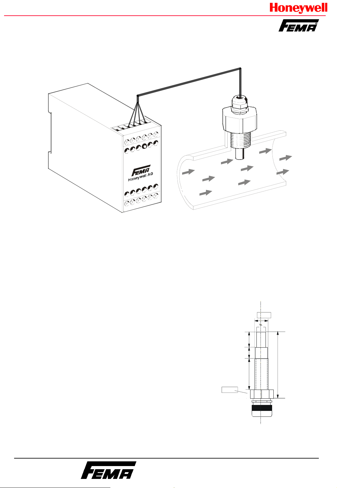
Mit dem Strömungssensor SWF62 und dem Auswertegerät ASW 454
kann die Strömung in Flüssigkeiten zuverlässig überwacht werden. Die
Empfindlichkeit kann mit einem Grob- und einem Feinpotentiometer
feinfühlig eingestellt werden. Der Schaltzustand wird durch eine LED
angezeigt.
Die Fühlerspitze muß vollständig umströmt werden.
Erst Sensor einschrauben, dann elektrisch verbinden!
Technische Daten des Sensors SWF...
G
1/4
"
Mediumstemperatur: 0...80 °C, bei höheren
Mediumstemperaturen (bis 120 °C) können
8,5
Schaltpunktverschiebungen auftreten, der
Sensor wird jedoch nicht beschädigt.
Max. zul. Druck: 20 bar
Anschlußleitung: 2,5 m, vieradrig
15
10
58
23
Sensorwerkstoff: Mediumsberührte Teile aus
1
W
S
Edelstahl 1.4571. Kabelverschraubung: Ms,
7
vernickelt
Schutzart: IP 65
Maximale Leitungslänge : 60 m abgeschirmtes
Kabel (4 x 1,5 qmm)
Honeywell GmbH
Telefon 07031/637-02
FEMA Regelgeräte
⋅
Postfach 1254 ⋅ 71099 Schönaich
⋅
Telefax 07031/637-850
7157 249 / 2
Page 2
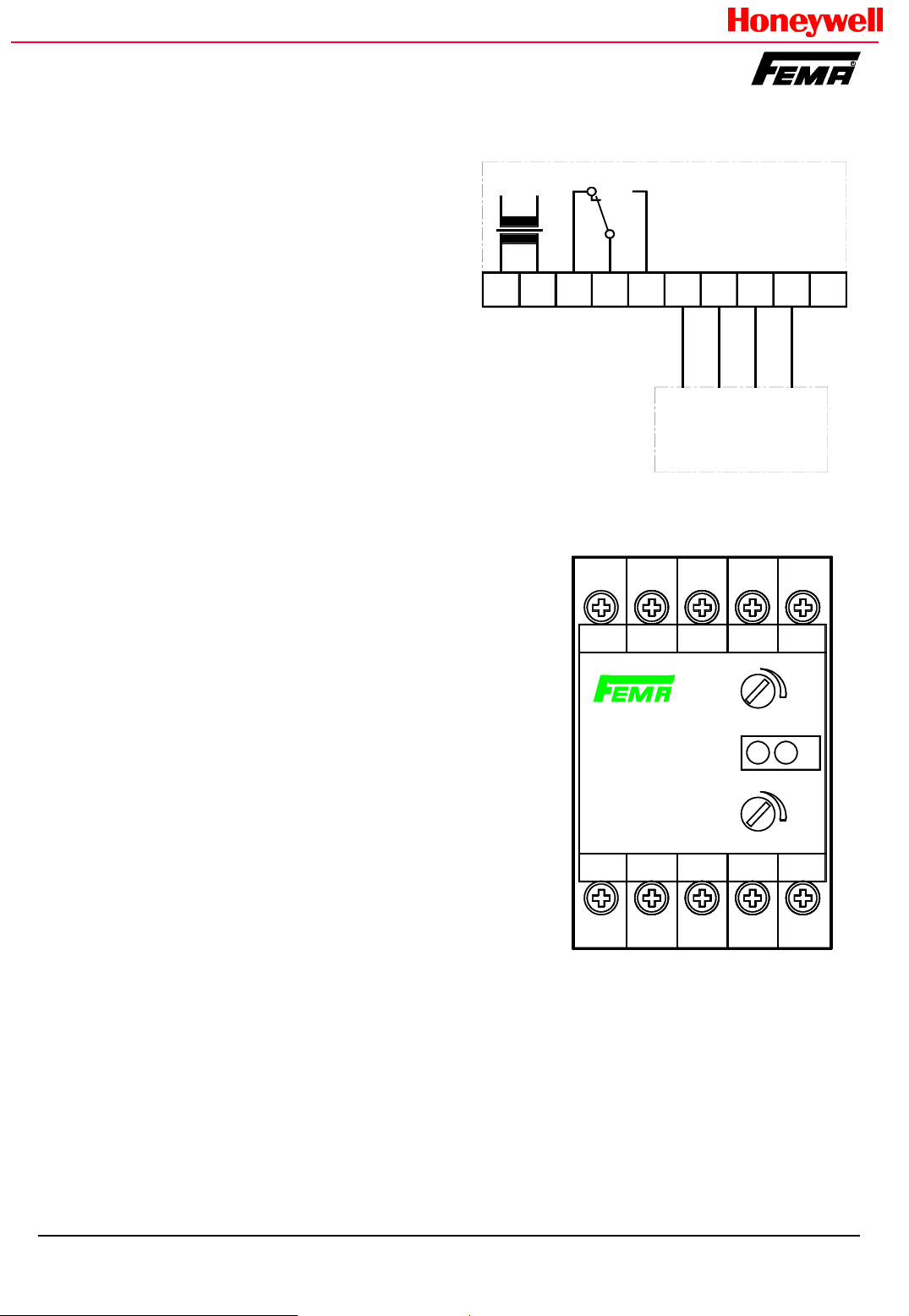
Elektrischer Anschluß
Der Sensor muß entsprechend dem
nebenstehenden Anschlußplan mit dem
Auswertegerät verbunden werden.
Vertauschung der Anschlüsse führt zu
Fehlfunktionen.
Wird die Fühlerleitung gemeinsam mit
anderen stromführenden Leitungen verlegt,
ist die Fühlerleitung abzuschirmen.
Die einschlägigen Vorschriften für die
Installation elektrischer Anlagen sind zu
beachten.
A2
A1
16
15 18
230 V AC
(24 V AC/DC)
ASW 454
ASW 454/24
GND
+
n
e
t
w
i
o
h
r
b
w
n
ß
u
i
a
e
r
b
w
K
F
w
n
o
e
l
l
e
r
e
y
g
n
b
l
ü
e
r
g
g
Auswertegerät ASW 454
Das Auswertegerät ist für Schaltschrankeinbau vorgesehen.
Montage auf Normschiene.
Inbetriebnahme
1. Trimmer „fein“ und „grob“ auf minimale Empfindlichkeit
einstellen (Linksanschlag).
2. Netzspannung anlegen. Die grüne LED leuchtet. Das Gerät
ist nach 2 sec betriebsbereit.
3. Strömungserzeuger einschalten
4. Trimmer „grob“ langsam in Richtung Maximum (+) drehen,
bis die gelbe LED leuchtet und das Ausgangsrelais anzieht.
5. Nach 2-3 Min. den Schaltpunkt mit dem Trimmer „fein“
kontrollieren und leicht über den Schaltpunkt hinwegdrehen.
6. Zur Überprüfung Strömungserzeugung abschalten oder
reduzieren. Die gelbe LED erlischt und das Ausgangsrelais
fällt ab.
Technische Daten :
Betriebsspannung: 230 V AC oder 24 V AC/DC (siehe
Typenschild)
Leistungsaunahme: ca. 3 VA
Schaltausgang: Relais, einpolig umschaltend, 8A, max.250 V
Umgebungstemperatur: 0 ... 60°C
Max. Temperaturgradient des Mediums: 10K/min
Empfindlichkeit : 0,1 - 3 m/s (flüssige Medien)
1 - 15 m/s (gasförmige Medien)
Schalthysterese: ca. 2% fest eingestellt
Ansprechzeit : 10 ... 60 sec.
Fühlerbruchsicherung: Bei Unterbrechung der Fühlerleitungen
wird abgeschaltet bzw. Unterbrechung der Strömung
signalisiert
Bauform: Normgehäuse N 45
Bei hohen Strömungsgeschwindigkeiten können schnelle
Temperaturänderungen Schaltvorgänge auslösen.
SWF...
SENSOR
A1
ASW 454
230 V AC
15 16 18
Einstellelemente
Empfindlichkeit, grob und fein,
(hohe Empfindlichkeit : niedriger
Schaltpunkt / Strömung)
grob : Grobeinstellung
fein : Feineinstellung (2-3min
nach Grobeinstellung)
Signallampen (LEDs) :
1 = Strömung vorhanden
2 = Speisespannung vorhanden
GND
+
FK
grob
rough
+
1 2
fein
fine
+
A2
7157 249 / 2
Page 3

Flow monitoring
Installation and operating instructions
The flow in fluids can be monitored reliably with the flow sensor
SWF... and the evaluation unit ASW 454. The sensitivity can be
adjusted accurately with a coarse (rough) and fine potentiometer. The
switching state is indicated by an LED.
The sensor element must be located in the flow.
Screw in sensor before fixing electrical connection
Technical data of the sensor SWF 62
Medium temperature: 0...80 °C, at higher
medium temperatures (up to 120°C), switching
G
1/4
"
8,5
15
point shifts can occur but the sensor is not
damaged..
Max. permissible pressure: 20 bar
10
58
23
Connection cable: 2.5 m, four-core
1
W
S
7
Sensor material: Parts in contact with medium
made of stainless steel 1.4571. Cable screw
union: brass nickel-plated.
Protective catagory: IP 65
Maximum cable length : 60 m shielded cable (4
x 1,5 mm)
Honeywell GmbH
Telefon 07031/637-02
FEMA Regelgeräte
⋅
Postfach 1254 ⋅ 71099 Schönaich
⋅
Telefax 07031/637-850
7157 249 / 2
Page 4

Electrical connection
The sensor must be connected with the
evaluation unit corresponding to the
adjacent connection diagram. Incorrect
connection leads to faulty operation.
If the probe cable is run together with other
current-conduction cables use a shielded
probe cable.
The relevant regulations for the
installation of electrical systems must be
complied with.
Evaluation unit ASW 454
The evaluation unit is intended for switchgear cabinet
installation on standard rails.
A2
A1
16
15 18
230 V AC
(24 V AC/DC)
ASW 454
ASW 454/24
GND
+
n
e
t
w
i
o
h
r
w
b
n
ß
u
i
a
e
r
b
w
K
F
w
n
o
e
l
l
e
r
e
y
g
n
b
l
ü
e
r
g
g
SWF...
Start-up
1. Turn „sensitivity“ potentiometers „rough“ and „fine“ to
minimum sensitivity.
2. Switch on power supply of ASW ... The green LED
switches on. After 2 sec. the device is ready for operation.
3. Switch on flow
4. Turn potentiometer „rough“ towards maximum (+) until
the yellow LED switches on and the output relay switches.
5. After 2-3 min. check the switching point with
potentiometer „fine“ and turn slightly further than the
switching point.
6. For verification of correct operation reduce or switch off
flow. The yellow LED will switch off and the output relay will
switch.
Technical data
Operating voltage: 230 V AC or 24 V AC/DC (see name
plate)
Power consumption: approx. 3 VA
Switching output: Relay, single-pole switch-over contact,
8 A, max. 250 V
Ambient temperature: 0 ... 60°C
Max. temperature gradient of the medium: 10 K/min
Sensitivity : 0.1 - 3 m/s (liquid media)
1 - 15 m/s (gaseous media)
Switching hysteresis: approx. 2 % set fixed
Reaction time : 10 - 60 sec.
Probe breakage protection: On interruption of the probe
cables, the device is switched off or interruption of flow is
signalled.
Type of construction: standard housing N45
Fast temperature changes may lead to switching when
monitoring high flow speed.
SENSOR
A1
ASW 454
230 V AC
15 16 18
Setting elements
Sensitivity, rough and fine
(high sensitivity for low
switching point / low flow
speed)
rough : primary adjustment
fine : for finetuning ( 2-3 min
after primary adjustment)
Signal lamps (LEDs)
1 = Flow present
2 = Supply voltage present
GND
+
FK
grob
rough
1 2
fein
fine
+
+
A2
7157 249 / 2
 Loading...