

Honeywell AlarmNet GSM-ANT3dB, 7845GSM, 7845i-GSM Installation Manual

K14441 8/06 Rev. A
AlarmNet
AlarmNet GSM
AlarmNet AlarmNet
GSM----ANT
GSMGSM
ANT3dB
ANTANT
3dB
3dB3dB
Remote
Remote Weatherproof
Remote Remote
Weatherproof Antenna
Weatherproof Weatherproof
Antenna
AntennaAntenna
Installation Guide
General
7845GSM and 7845i-GSM Communication Modules both come equipped with internal dual band cellular
antennas. In most cases, this antenna will provide a sufficient received signal strength indication (RSSI) for
a successful installation.
The Honeywell GSM-ANT3dB Remote Weatherproof Antenna should be used in installations where the
antenna must be mounted outdoors at some distance from the radio and gain is needed.
Signal Strength
For reliable service, 7845GSM and 7845i-GSM should only be installed in locations where the RSSI is a
minimum of three bars. RSSI is a measure of how well the 7845GSM is receiving the cell tower.
The RSSI value measured in dBm can be viewed using the 7720P Programming Tool, by using the shift <E>
command.
Installation Guidelines
By following a few simple guidelines, you can maximize the performance of 7845GSM / 7845i-GSM using the
internal antenna and simplify your installation.
If a consistent RSSI of three bars cannot be found with the internal antenna, an external antenna should be
used.
dBm is displayed as a negative value on the 7720P and a lower negative number is better.
i.e.: -60 dBm is a better RSSI than -100 dBm.
• Find the best coverage before mounting and wiring into the radio by moving 7845GSM to several
locations while monitoring the RSSI.
• The best RSSI can usually be found at the highest point in the building on an exterior wall. Avoid
the basement.
• Maintain at least 12 inches of clearance between 7845GSM and steel I-beams, HVAC ducts, metal
studs, steel roofs, exterior walls with metalized insulation or aluminum siding and other large metal
objects.
External Antenna
The GSM-ANT3dB is an exterior weatherproof antenna that can be mounted up to 50 feet away from the
radio when the proper coax cable is used. Refer to Table 1 for coax cable selection. Install the GSM-ANT3dB
as follows:
1. Measure and record the 7845GSM RSSI using the internal antenna for reference.
2. Disconnect all power from the unit including the battery.
3. Remove plastic plug from the SMA mounting hole on top of the 7845GSM and insert the SMA end of
the adapter cable. Secure the SMA connector with the included washer and nut.
4. Plug the MMCX end of the adapter cable into the external antenna port and route cable as shown.
5. Attach the antenna and ground plane to the mounting bracket as shown in Figure 1.
6. Find a suitable location so that the antenna will be mounted vertically:
• The best antenna location is usually at the highest point within the building. Avoid the basement.
• Maintain at least 12 inches of clearance between the antenna and large metal objects.
7. Route the coax cable and make all required connections.
8. Restore power to the unit, measure the RSSI and compare the new value to the value recorded in
Step 1.
9. Adjust the location of the antenna if needed to maximize the RSSI, for at least three bars.
10. Permanently mount the antenna vertically using the hardware as shown. The included silicon
rubber tape is used to waterproof the antenna connection
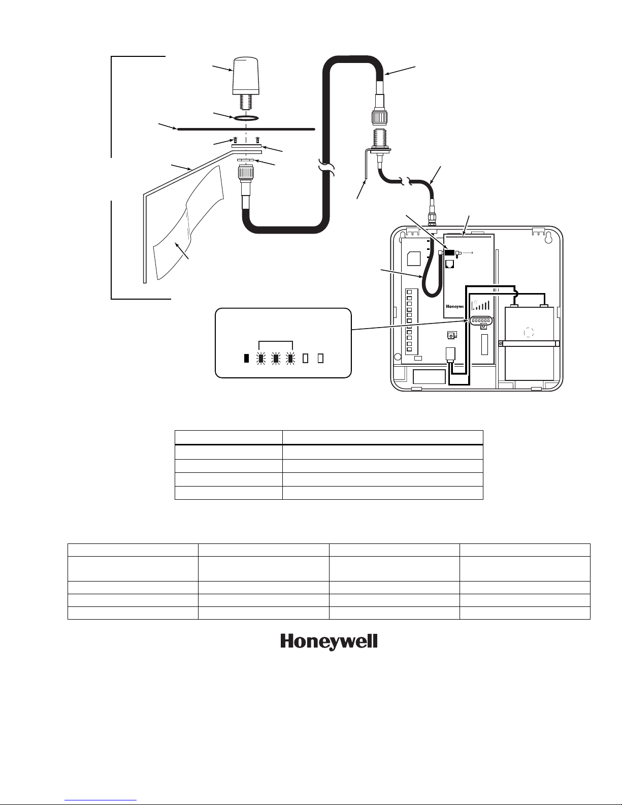
ANTENNA
7626-50HC
7626-25HC
7626-12
7626-5
O-RING
SCREWS (4)
SILICON
TAPE
WRAP
INSULATOR
NUT
SMA / MMCX ADAPTER CABLE
SIGNAL STRENGTH (RSSI) FUNCTION
Select a site where signal strength is 3 - 5 bars lit solid.
Min. Lit
ON
LED DISPLAY
GYGGRY
BRACKET
EXTERNAL
ANTENNA
PORT
TB 1
WA7626-CA CABLE
FOR EXTERNAL ANTENNA
50 OHM MMCX ONLY
PRIMARY POWER: 9 - 16.5 VAC
CURRENT: 900mA PEAK, 70mA STANDBY
BATTERY: 8V. 3.1 AHr FOR 24 Hr BACKUP
FCC:XXXXXXXXXX IC: YYYYYYYYYY
1
2
3
4
5
6
7
8
9
10
11
INTERNAL
ANTENNA
7720P PROGRAMMER PORT
NOT FOR TELEPHONE SERVICE USE!
GPRS
RSSI
IBS
M0
M1
BLK
RED
BLACK
GSM-ANT 3dB
GROUND
PLANE
BRACKET
Figure 1 – GSM-ANT3dB Remote, Weatherproof Antenna Installation
Kit Part No. Includes:
GSM3dB50KT 7626-50HC, 50 ft., RG8 cable
GSM3dB25KT 7626-25HC, 25 ft., RG8 cable
GSM3dB12KT 7626-12, 12 ft., RG142 cable
GSM3dB5KT 7626-5, 5 ft., RG142 cable
Table 1: GSM-ANT3dB Antenna Kits
SPECIFICATIONS:
Type: Dual band, field diverse Input Power (Max.) 100W
Bands: 824-896 MHz
VSWR: <2:1
1850-1990 MHz
Polarization: Vertical and horizontal Dimensions: 3.15" x 1.44"
Gain (Average): 3dBi Randome Material: ABS, black
Impedance: 50 Ohms Connector Type: Type N female
RED
7845GSM-029-V0
ÊK14441(Š
K14441 8/06 Rev. A
165 Eileen Way, Syosset, New York 11791
Copyright © 2006 Honeywell International Inc.
www.honeywell.com/security
 Loading...