

Page 1
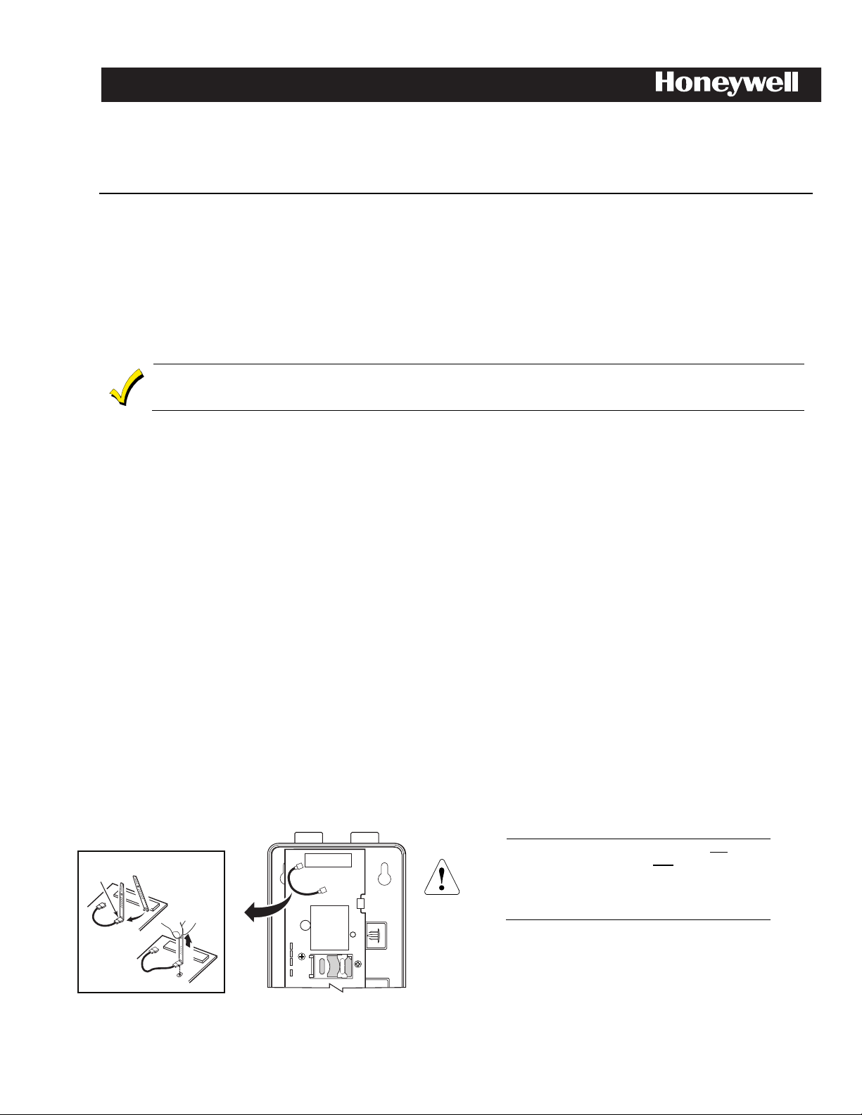
Antenna Cable Removal Tool
cell-ant3dB-002-V0
DETAIL A
2
ANTENNA
CABLE
REMOVAL
TOOL
SEE
DETAIL A
1
Insert tool
under RF
Connector
(not wire)
Pull up
3
!
AlarmNet CELL-ANT Indoor Fixed Length Antenna
Installation Guide
General
The Communication Module uses an internal dual band cellular antenna. In most cases, this antenna will provide a sufficient received signal
strength indication (RSSI) for a successful installation.
The Indoor Fixed Length Antenna should be used in installations where moving the antenna to a higher point within the building will provide
better RSSI.
Signal Strength
For reliable service, communication module should only be installed in locations where there is satisfactory signal strength. The signal strength
LED (green) lights steady to indicate satifasfactory signal strength. The signal strength value measured in dBm can be viewed on the 7720P
Programming Tool, by using the shift <E> command.
Installation Guidelines
Use these guidelines to maximize the performance of the module and simplify your installation.
If consistent signal strength cannot be found with the internal antenna, an external antenna should be used.
dBm is displayed as a negative value on the 7720P and a smaller negative number is better.
i.e., -60 dBm is a better signal strength than -100 dBm.
• Find the best coverage before mounting and wiring the radio by moving the module to several locations while monitoring the signal
strength.
• The best signal strength can usually be found on an exterior wall at the highest point in the building. Avoid the basement.
• Maintain at least 12 inches of clearance between the module and steel I-beams, HVAC ducts, metal studs, steel roofs or roofs,
exterior walls with metalized insulation or aluminum siding and other large metal objects.
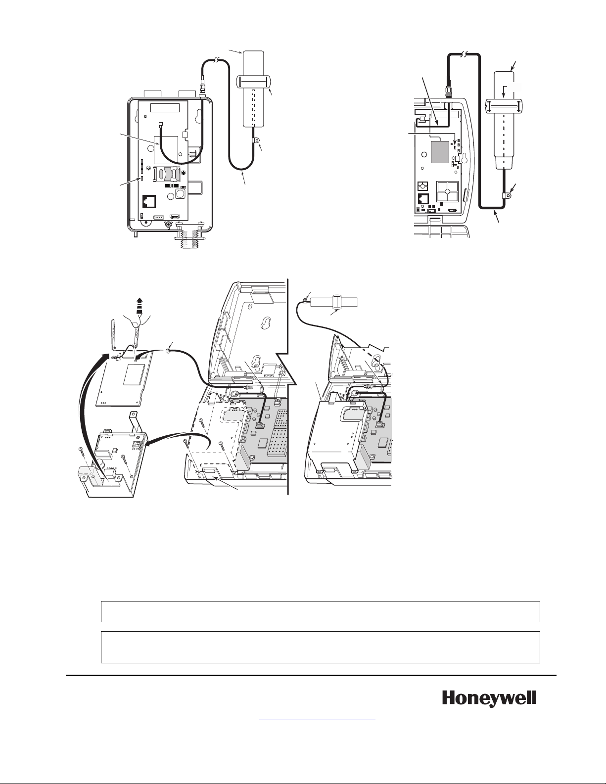
Indoor Antenna
The antenna is not weatherproof, and must be installed indoors and mounted vertically while maintaining 12 inches of clearance from large
metal objects. Install the antenna as follows:
1. Measure and record the communication module signal strength using the internal antenna for reference.
2. Disconnect all power from the unit, including the battery.
3. Remove plastic plug from the SMA mounting hole on top of the communication module housing, and insert the SMA end of the
adapter cable.
4. Secure the SMA connector with the included washer and nut.
5. Plug the u.FL connector on the other end of the adapter cable into the external antenna port and route cable as shown.
6. Find a suitable location that will allow the antenna to be mounted vertically.
7. Route the antenna cable and connect the SMA to the module.
8. Restore power to the unit, measure the signal strength and compare the new value to the value recorded in step 1.
9. If needed, adjust the location of the antenna until the signal strength LED lights green.
10. Permanently mount the antenna vertically using the included hardware.
1. Slip the Antenna Cable Removal Tool (p/n 700-03513) under RF
Cable connector as shown.
PLEASE: (1) DO NOT use the tool to pry the
connector loose. Instead, pull directly upward,
perpendicular to the circuit board. Do not pull
2. Pull directly upwards until the connector detaches from the
module’s receptacle as shown in Detail A. (This cable is no
longer needed.)
3. Repeat step 1 and 2 to disconnect the cable from the GSMX4G.
(This cable is no longer needed.)
on the cable. (2) USE CAUTION not to damage
the adjacent components when inserting the
Antenna Cable Removal Tool.
Page 2
Antenna
Cable
Mount
External
Antenna
Clamp
cell-ant-002-V1
Signal Strength
LED (GREEN)
ON - Satisfactory
Signal
OFF - Unsatisfactory
Signal
Adapter
Cable
Cell-Ant-004-V0
Antenna
Cable
External
Antenna
Adapter
Cable
Clamp
ON = Satisfactory
Signal
OFF = Unsatisfactory
Signal
Mount
Signal Strength
LED (GREEN)
Locking tabs
TIE
WRAP
TIE
WRAP
Connect
Antenna
Adapter
Cable
Board
cell-ant-005-V0
CDMA-L57
7
Insert tool
under each RF
connector
(Not the wire)
Remove
screws
(3)
5
Pull UP
1
2
3
4
(2)
6
8
Turn Over
Removal Tool
External
Antenna
9
Clamp
Mount
10
Re-install
Connector
Board
Connect
Antenna
Cable
GSMV4G and GSMX4G Communication Modules
Warning – The internal or external antenna(s) used with this product must be installed to provide a separation distance of at least 7.8 in. (20 cm)
from all persons and must not be co-located or operating in conjunction with any other antenna or transmitter except in accordance with FCC
multi-transmitter product procedures.
Exposition aux Fréquences Radio: L'antenne (s) utilisée pour cet émetteur doit être installée à une distance de séparation d'au moins 7,8
pouces (20 cm) de toutes les personnes.
CDMA-L57 Communication Module
Ê800-20799"Š
800-20799 8/15 Rev. A
IMPORTANT NOTE ABOUT EXTERNAL ANTENNAS
If an external cellular radio antenna is used, the antenna may be installed or replaced ONLY by a professional installer.
TO THE INSTALLER
For the communication module, the external antenna must not exceed a maximum directional gain (including cable loss)
of 3.2 dBi at 850 MHz and 2.3 dBi at 1900 MHz.
GSMVLP Series Communication Module
RF Exposure
Mise en Garde
2 Corporate Center Drive, Suite 100
P.O. Box 9040, Melville, NY 11747
2015 Honeywell International Inc.
www.honeywell.com/security
SPECIFICATIONS:
Frequency Range: 824-896 MHz
1850-1990 MHz
Average Gain: 1dBi
Maximum power: 10W
Nominal impedance: 50 Ohms
Pattern: Omni Directional
Termination: SMA Male
Type: Dual band, dipole, PCB
Polarization: Linear
VSWR: <2:1
Dimensions: 143 x 27 mm
Cover: Polyolefin, black
Cable Type: RG-174
Cable Length: 3m
For Indoor Use Only
 Loading...