

Page 1

A
A
AA
A
A
AA
D
D
DD
D
D
DD
EEEE
EEEE
M
M
MM
M
M
MM
C
C
CC
C
C
CC
O
O
OO
O
O
OO
8888
8888
1111
1111
3333
3333
2222
2222
////
////
8888
8888
1111
1111
3333
3333
2222
2222
----
----
iiii
iiii
SSyymmpphhoonnyy//SSyymmpphhoonnyy--ii
AAddvvaanncceedd UUsseerr IInntteerrffaaccee
User Guide
K5763V4 10/07 Rev. A
Page 2

Page 3

Table of Contents
ABOUT SYMPHONY/SYMPHONY-I..........................................................................................7
Introduction to Symphony/Symphony-i.................................................................................................................7
The Symphony/Symphony-i Interface..................................................................................................................7
Navigating through Symphony/Symphony-i .........................................................................................................8
About Your Home Screen .................................................................................................................................... 8
Symphony/Symphony-i "Arming" Screen ........................................................................................................... 10
SYSTEM OVERVIEW ..............................................................................................................11
Introduction to Your System...............................................................................................................................11
Burglary Protection.............................................................................................................................................11
Partitions...................................................................................................................................................................11
Zones ..........................................................................................................................................................................11
Entry/Exit Delays ...................................................................................................................................................11
Alarms........................................................................................................................................................................12
Memory of Alarm.....................................................................................................................................................12
Fire Protection....................................................................................................................................................12
User Codes ........................................................................................................................................................ 12
Internet Features................................................................................................................................................ 12
Extended Functionality.......................................................................................................................................13
SECURITY SYSTEM OPERATION .........................................................................................15
Introduction to Security System Operation.........................................................................................................15
How to Arm the System .....................................................................................................................................15
How to Arm Multiple Partitions ...........................................................................................................................17
Keyswitch Operation .......................................................................................................................................... 18
How to Arm Using a Keyswitch..........................................................................................................................18
How to Bypass Zones ........................................................................................................................................ 19
How to Remove Bypassed Zones...................................................................................................................... 21
How to Disarm the System ................................................................................................................................22
How to Disarm Using a Keyswitch ..................................................................................................................... 24
How to Check the Status of Other Partitions .....................................................................................................24
How to Send Emergency Messages..................................................................................................................26
How to View the Event Log................................................................................................................................27
FIRE ALARM SYSTEM OPERATION ......................................................................................29
Introduction to Fire Alarm System Operation .....................................................................................................29
In Case of Fire Alarm ......................................................................................................................................... 29
Silencing a Fire Alarm ........................................................................................................................................29
Fire Display Lock................................................................................................................................................29
Recommendations for Proper Protection...........................................................................................................30
Recommendations For Smoke And Heat Detectors.......................................................................................... 30
3
Page 4

Table of Contents (Cont'd)
Recommendations For Proper Intrusion Protection...........................................................................................31
Recommendations for Evacuation..................................................................................................................... 31
USER CODE SETUP ...............................................................................................................33
Introduction to User Code Setup........................................................................................................................ 33
How to Access User Setup ................................................................................................................................33
How to Add a User.............................................................................................................................................35
How to Delete a User.........................................................................................................................................38
How to Edit a User ............................................................................................................................................. 39
INTERNET FEATURES ...........................................................................................................41
Introduction to Internet Features........................................................................................................................41
Modifying Your WEB Page ................................................................................................................................41
Content.......................................................................................................................................................................43
Stock Quotes ................................................................................................................................................................44
Stock Selections for rick .........................................................................................................................................44
My Email .....................................................................................................................................................................44
Horoscopes..................................................................................................................................................................45
Sports Scoreboard .......................................................................................................................................................45
Weather........................................................................................................................................................................46
Reminders .................................................................................................................................................................46
Manage Users...........................................................................................................................................................47
Edit Profile................................................................................................................................................................49
Remote Control.........................................................................................................................................................49
User Feedback.............................................................................................................................................................51
Logout ........................................................................................................................................................................51
ADVANCED SYSTEM FEATURES..........................................................................................53
Introduction to Advanced System Features ....................................................................................................... 53
Keypad (Console) Emulation Mode ...................................................................................................................53
How to Enter Console Emulation Mode ............................................................................................................. 53
SUMMARY OF AUDIO NOTIFICATION...................................................................................55
SUMMARY OF SYMPHONY/SYMPHONY-I LED OPERATION..............................................57
Symphony/Symphony-i LED Operation..............................................................................................................57
LEDs During Normal (Idle) State........................................................................................................................57
LEDs During Software Downloading .................................................................................................................57
LED Operation When Software Download Fails..............................................................................................58
SYMPHONY/SYMPHONY-I SETUP ........................................................................................59
How to Access Symphony/Symphony-i Setup Options......................................................................................59
How to Access Setup.........................................................................................................................................59
4
Page 5

Table of Contents (Cont'd)
How to Adjust the Touch Screen Contrast.........................................................................................................60
How to Adjust the Volume.................................................................................................................................. 61
How to Select Screen Saver Activation Time .................................................................................................... 61
How to Set the Time and Date...........................................................................................................................63
Time Zones................................................................................................................................................................64
How to Calibrate the Touch Screen ................................................................................................................... 65
Replacing Batteries In Wireless Sensors...........................................................................................................69
Silencing Low Battery Warning Tones at the Keypad ........................................................................................69
How to Clean your Symphony/Symphony-i........................................................................................................70
Routine Care......................................................................................................................................................71
GLOSSARY..............................................................................................................................73
5
Page 6

Table of Contents (Cont'd)
6
Page 7

Introduction to Symphony/Symphony-i
Congratulations on your ownership of a Honeywell Security System. You've made a
wise decision in choosing it, for it represents the latest in security protection
technology today.
This security system offers you three forms of protection: burglary, fire and
emergency. To realize the full potential of the system, it is important that you feel
comfortable operating it. Your system may consist of:
• Symphony/Symphony-i Advanced User Interface
• One or more Keypads for system control
• Various sensors for perimeter and interior burglary protection, plus a selected
number of strategically placed smoke or combustion detectors
About Symphony/Symphony-i
• Home automation devices.
UL
The control of the home environment feature has not been evaluated by UL.
The system uses microcomputer technology to monitor all zones, and provides
appropriate information for display on the Symphony/Symphony-i and/or Keypads
used with the system. Your system may also have been programmed to
automatically transmit alarm or status messages over the phone lines to a central
alarm monitoring station.
The Symphony/Symphony-i Interface
Symphony/Symphony-i is an intuitive, graphical interface that combines security
and home control with interactive Internet features. With clear, simple controls on a
touch-screen interface, the entire family will find Symphony/Symphony-i both easy
to learn and easy to use.
As a security and home-automation control, Symphony/Symphony-i can be used for:
• Quick and easy security system operation
• Control of the home environment, including the heating and air-conditioning
UL
system, lights, garage door, etc.
The control of the home environment feature has not been evaluated by UL.
As a household Internet appliance, Symphony/Symphony-i provides access to a
wealth of information, including:
• News
• Sports
7
Page 8
About Symphony/Symphony-i (cont'd)
• Weather
• e-mail, and
• Live updates of user-selectable content such as your horoscope.
Keeping pace with advances in technology, Symphony/Symphony-i will continue to
provide additional Internet functionality, as it becomes available.
Navigating through Symphony/Symphony-i
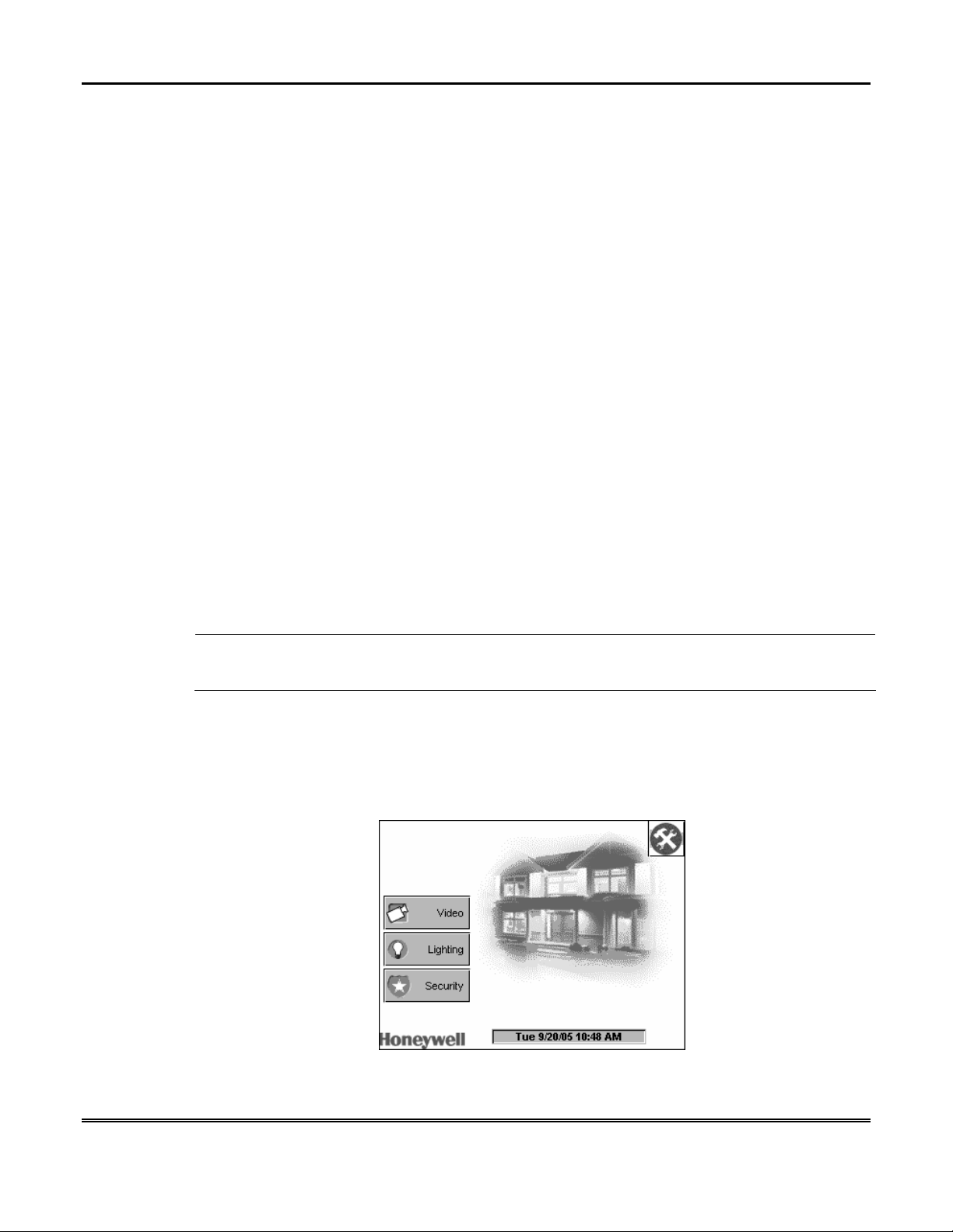
Navigation through Symphony/Symphony-i typically begins from the "Home"
screen. This is Symphony/Symphony-i’s main default screen (starting screen) and is
the first screen you will see when Symphony/Symphony-i is powered up and
initialized. It is from this screen that you will select from the main menu. Once you
have made your selection, you will navigate through various sub-menus by touching
buttons or icons to perform the function you desire.
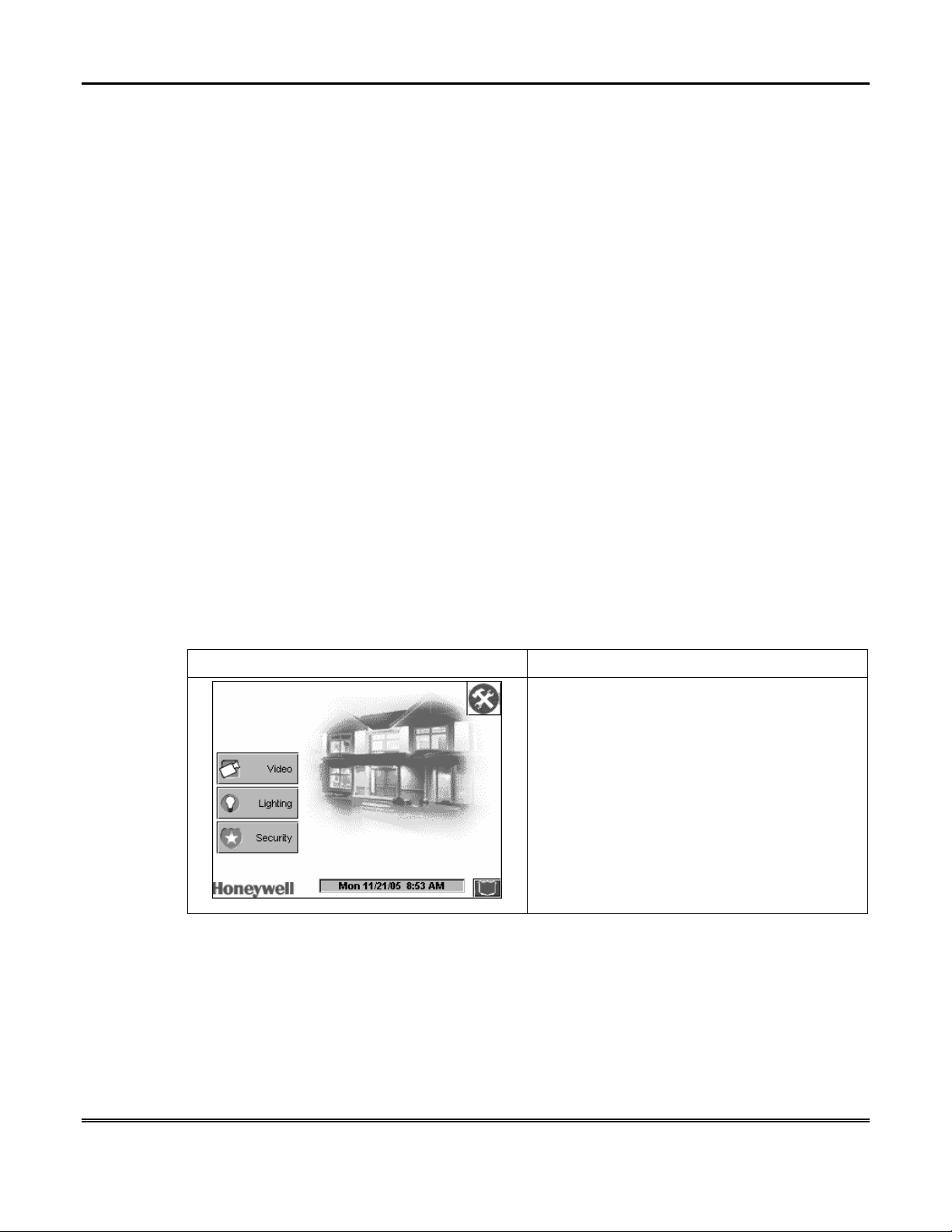
About Your Home Screen
Your "Home" screen is the gateway to your Symphony/Symphony-i Advanced User
Interface. From this screen you can:
UL
• access e-mail messages
• control the premises lighting, and most importantly,
• control your security system.
The control of the home environment feature has not been evaluated by UL.
Besides using your personal "Home" screen for E-mail messages, you may also
receive news/display and retrieve additional information of your choosing.
Your "Home" screen is displayed at all times, except when the system is armed or
you select another screen option.
8
Symphony/Symphony-i Icon/Button Descriptions
Page 9
About Symphony/Symphony-i (Cont'd)
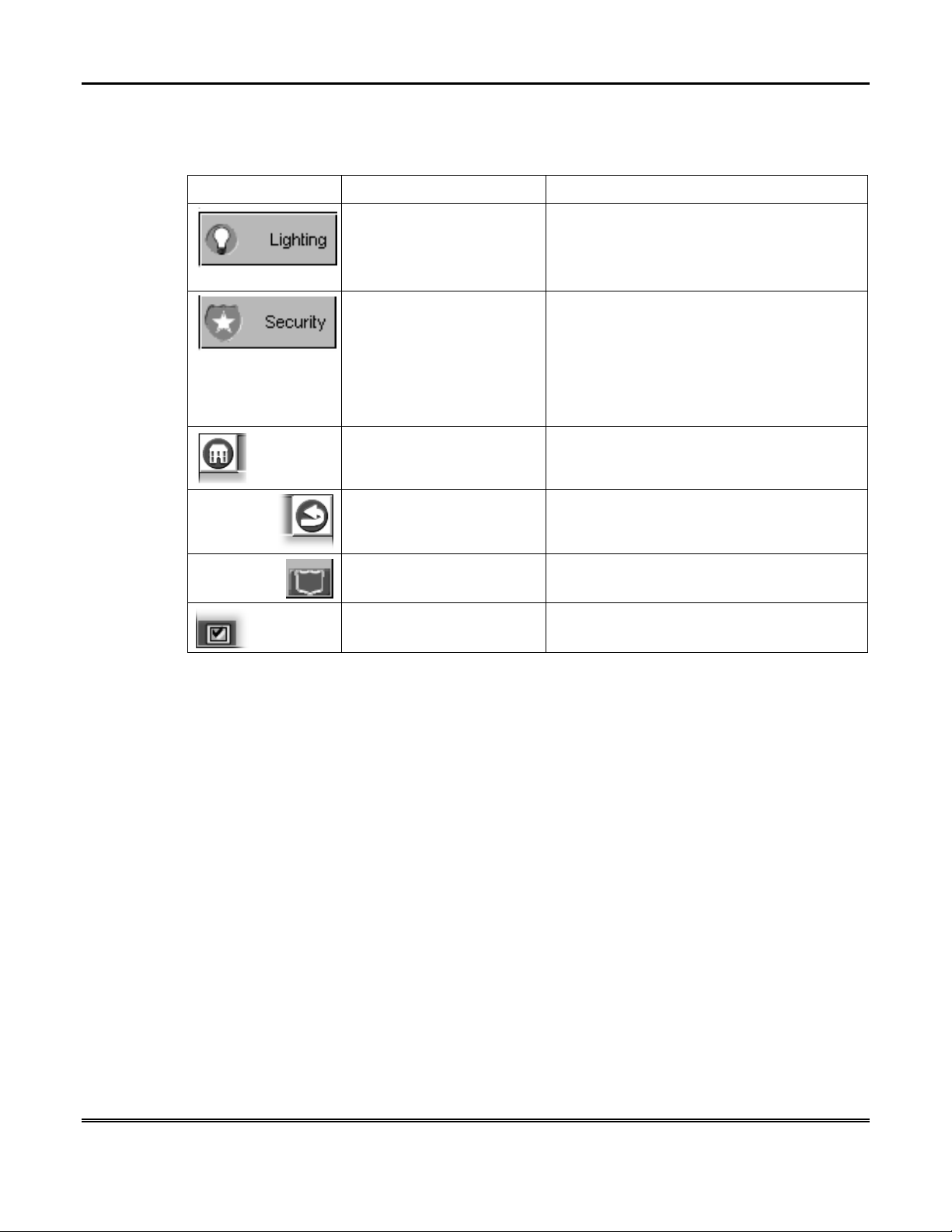
To aid in the navigation of Symphony/Symphony-i, a set of user-friendly icons has
been provided. The appearance, function, and location of these icons are described
below:
ICON/BUTTON LOCATION FUNCTION
"Home" screen Allows you to turn certain devices on and off
(if installed and programmed by your
installer.)
"Home" screen Accesses "Arming" screen.
NOTE: The background color of the shield
indicates security system status.
Upper left corner of most
screens
Upper right corner of most
screens
Lower right corner of most
screens
Lower left corner of most
screens
Green – system disarmed, ready to arm
Red – system armed
Yellow – system not ready to arm
Returns you to the Symphony/Symphony-i
"Home" screen.
Reverts to the last screen viewed.
Displays Emergency functions (as
programmed by your installer.
Used for Remote Security Access features.
9
Page 10
About Symphony/Symphony-i (cont'd)
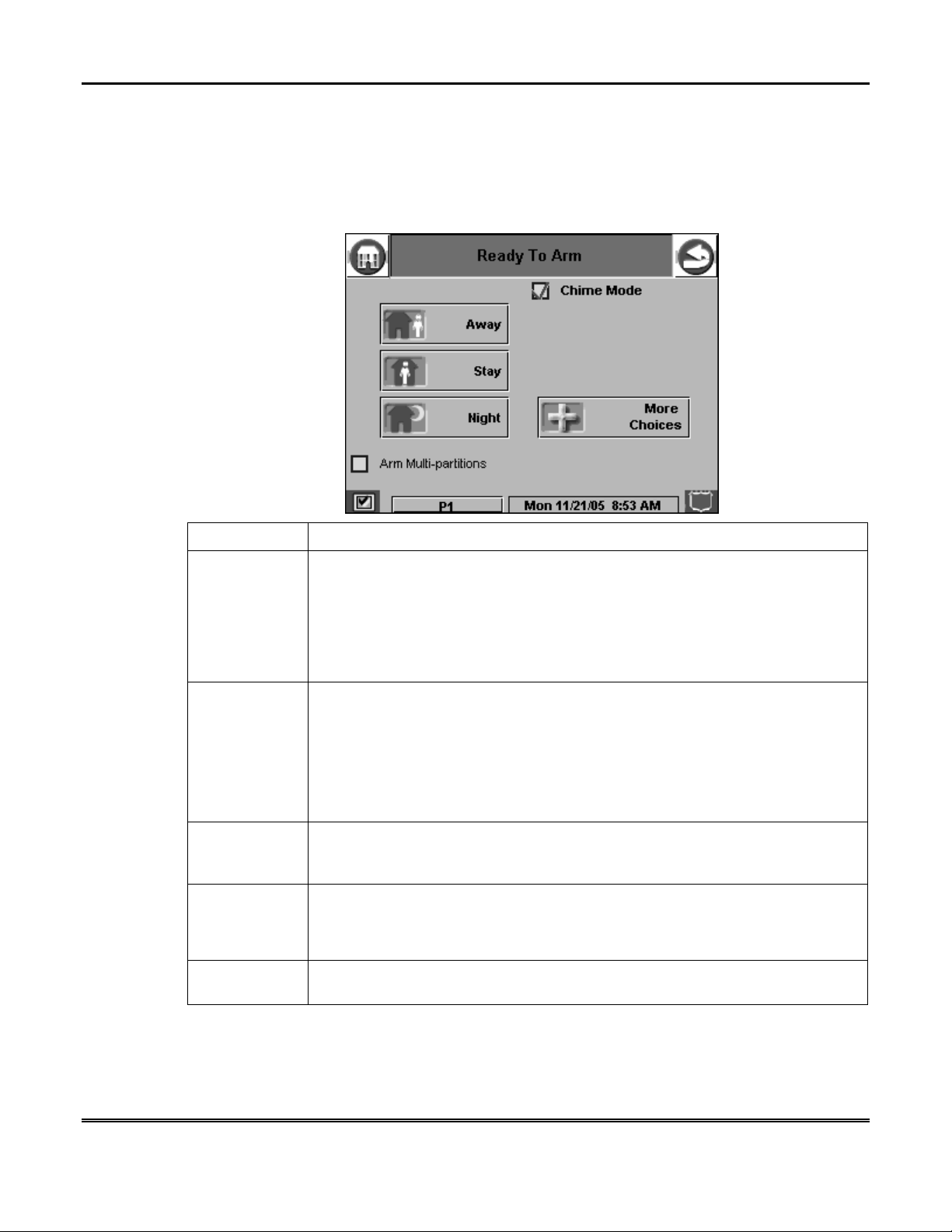
Symphony/Symphony-i "Arming" Screen
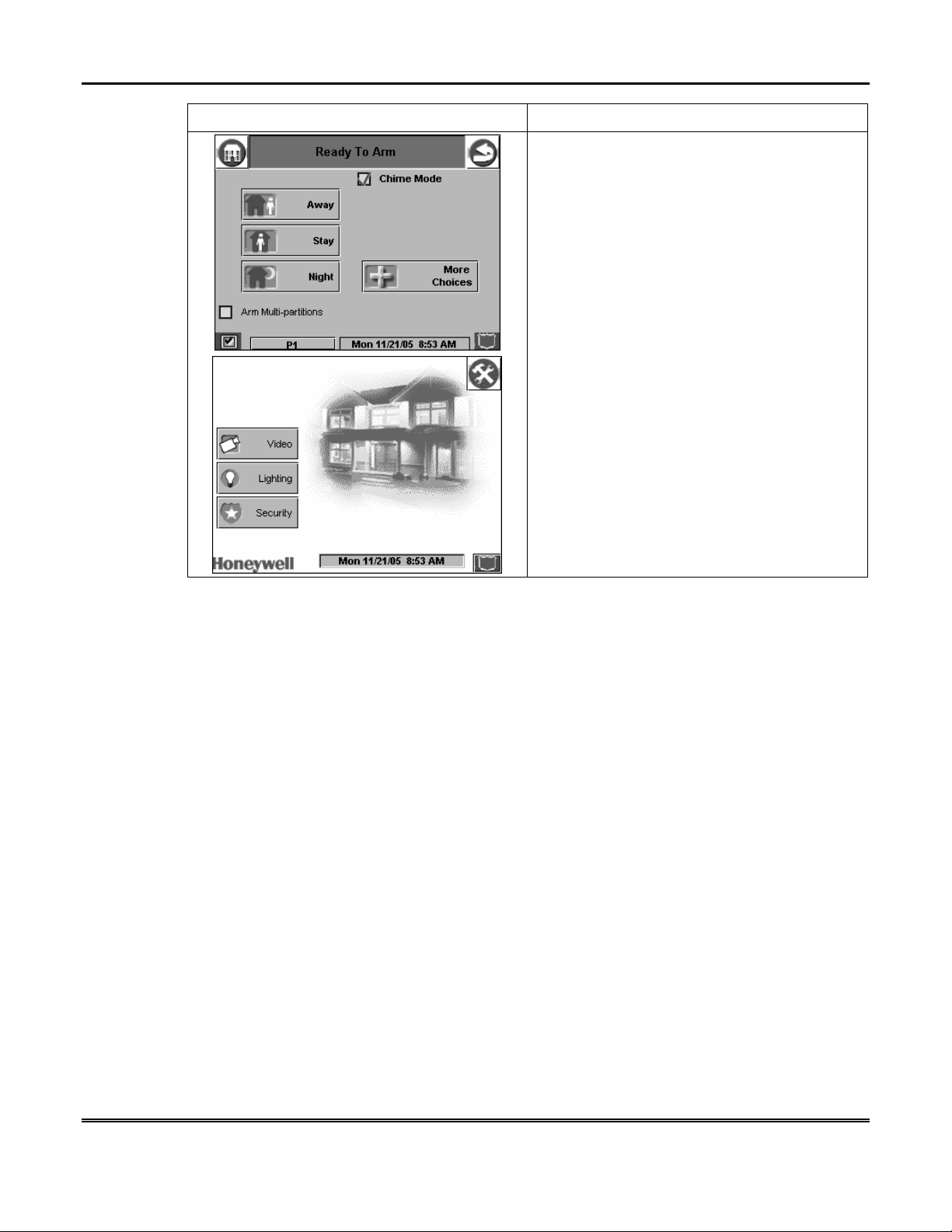
From the "Home" screen, press Security to access the Symphony/Symphony-i
"Arming" screen. Use this picture and the table that follows to become familiar with
the Symphony/Symphony-i security functions.
ITEM FUNCTION
Away
Stay
Night
Arm MultiPartitions
More Choices
Press this button to arm when no one will be staying on the premises. When
armed in Away, the system will sound an alarm if a protected door or window is
opened, or if any movement is detected inside the premises. You may leave
through the entrance door during the exit delay period without causing an
alarm. You may also re-enter through the entrance door, but must disarm the
system with your User Code within the entry delay period or an alarm will
occur.
Press this button to arm when you are staying home, but might expect
someone to use the entrance door later.
When armed in Stay, the system will sound an alarm if a protected door or
window is opened, but you may otherwise move freely throughout the
premises. Late arrivals can enter through the entrance door without causing an
alarm, but they must disarm the system within the entry delay period or an
alarm will occur.
Press this button to arm when you are staying home and do not expect anyone
to use the entrance door.
differently; have him/her describe the actual settings of this mode.
Check this box when you want to arm more than one partition. W hen Arm
Multi-Partitions is checked, all partitions within the system can be armed at one
time (if the user is so authorized). When the Arm Multi-Partitions circle does
not contain a check mark, each partition must be armed individually.
Press this button for to access Console Mode, show zone status, check the
event logs or to refresh your web information.
Your installer may have configured Night Mode
10
Page 11

Introduction to Your System
This system offers you three forms of protection: burglary, fire and emergency.
Monitoring is accomplished with various contact and motion sensors for perimeter
and interior burglary protection, plus strategically placed smoke, heat, or
combustion detectors.
Burglary Protection
The burglary protection portion of your system must be turned on or "armed" before
it will sense burglary alarm conditions. Your system provides three modes of
burglary protection: Away, Stay, and Night, and even allows you to “bypass”
selected zones of protection while leaving the rest of the system armed (e.g. this
enables you to arm the system but leave upper-story windows open.)
The system also provides a Chime mode, for alerting users to the opening and
closing of doors and windows even while the system is disarmed.
System Overview
Partitions
This system may e configured to arm and disarm more than one area, each as if it
had its own control. These areas are called partitions. Partitions are used when
the user wants to disarm certain areas while leaving other areas armed, or to limit
access to certain areas to specific individuals. Each user of the system can be
authorized to operate all or only some partitions, and can be given different
privileges in each. Information about Partitions is presented later in this document.
Zones
Your system's sensing devices have been assigned to various "zones." For example,
the sensing device on your Entry/Exit door may have been assigned to zone 001,
sensing devices on windows in the master bedroom to zone 002, and so on. These
numbers will appear on the display, along with an alpha descriptor for that zone (if
programmed), when an alarm or trouble condition occurs.
Entry/Exit Delays
Your system has preset time delays, referred to as exit delay and entry delay.
Whenever you arm your system, exit delay gives you time to leave through the
designated exit door without setting off an alarm. Exit delay begins immediately
after entering any arming command, and applies to all modes of arming protection.
If programmed, a slow beeping will sound throughout the exit delay period.
Entry delay gives you time to disarm the system when you reenter through the
designated entrance door. But the system must be disarmed before the entry delay
period ends, or an alarm will occur. The Keypad will beep during the entry delay
period, reminding you to disarm the system. Ask your installer about the delay
times programmed into your system.
11
Page 12

System Overview (cont'd)
Alarms
When an alarm occurs, Symphony/Symphony-i (and any other Keypads) and
external sounders will sound, and the zone(s) causing the alarm are displayed. If
your system is connected to a central monitoring station, an alarm message will also
be sent. To stop the alarm sounding, simply disarm the system.
Memory of Alarm
When an alarm condition occurs, the number(s) of the zone(s) that caused the
problem are displayed, along with the type of alarm (e. g. FIRE, ALARM). These
remains displayed until cleared by disarming the system.
Fire Protection
The fire protection portion of your security system (if used) is always on and will
sound an alarm if a fire condition is detected.
User Codes
Each user must be assigned a name with a corresponding 4-digit user code in order
to gain access to various features and functions. Through Symphony/Symphony-i,
you may program users to access any and all of the following systems:
• Fire/Burglary
• Internet
Users for the systems are programmed in a central user setup location that provides
the specific questions for the user pertaining to each system. You may want these
users to be the same, but there are situations in which you may want a user to have
access to one system (e.g., Internet) without having access to another (e.g., the
Fire/Burglary system).
Internet Features
As a household Internet appliance, Symphony/Symphony-i provides access to a
wealth of information, including:
• News
• Sports
• Weather
• E-mail, and
• Updates of user-selectable content such as your horoscope.
Additionally, you may control all of Symphony/Symphony-i’s functions from any
personal computer or laptop that has Internet capabilities, including security
system functions (arming, disarming, etc.).
12
Page 13

Extended Functionality
Extended functions are advanced functions that can be accessed through a standard
Alpha Keypad or through emulation mode on your Symphony/Symphony-i touch
screen. Refer to your Control Panel User Guide for these features.
System Overview (Cont'd)
13
Page 14

System Overview (cont'd)
14
Page 15
Introduction to Security System Operation
You can arm your system in one of three arming modes: Away, Stay, and Night.
The following table lists the three different arming modes and the results of each
FEATURES FOR EACH ARMING MODE
Arming Mode Exit Delay Entry Delay Perimeter Armed Interior Armed
Away Yes Yes Yes Yes
Stay Yes Yes Yes No
Night* Yes Yes (set for
*Your installer may have configured Night Mode differently; have your installer
write the actual mode settings above.
Security System Operation
Away or Stay
Mode)
No (set for
Instant or
Maximum Mode)
.
Yes Yes (set for
Away Mode)
No (set for Stay,
Instant or
Maximum Mode)
How to Arm the System
Arming the system in any mode is performed in the same way, as described below.
NOTE: Close all perimeter windows and doors before arming.
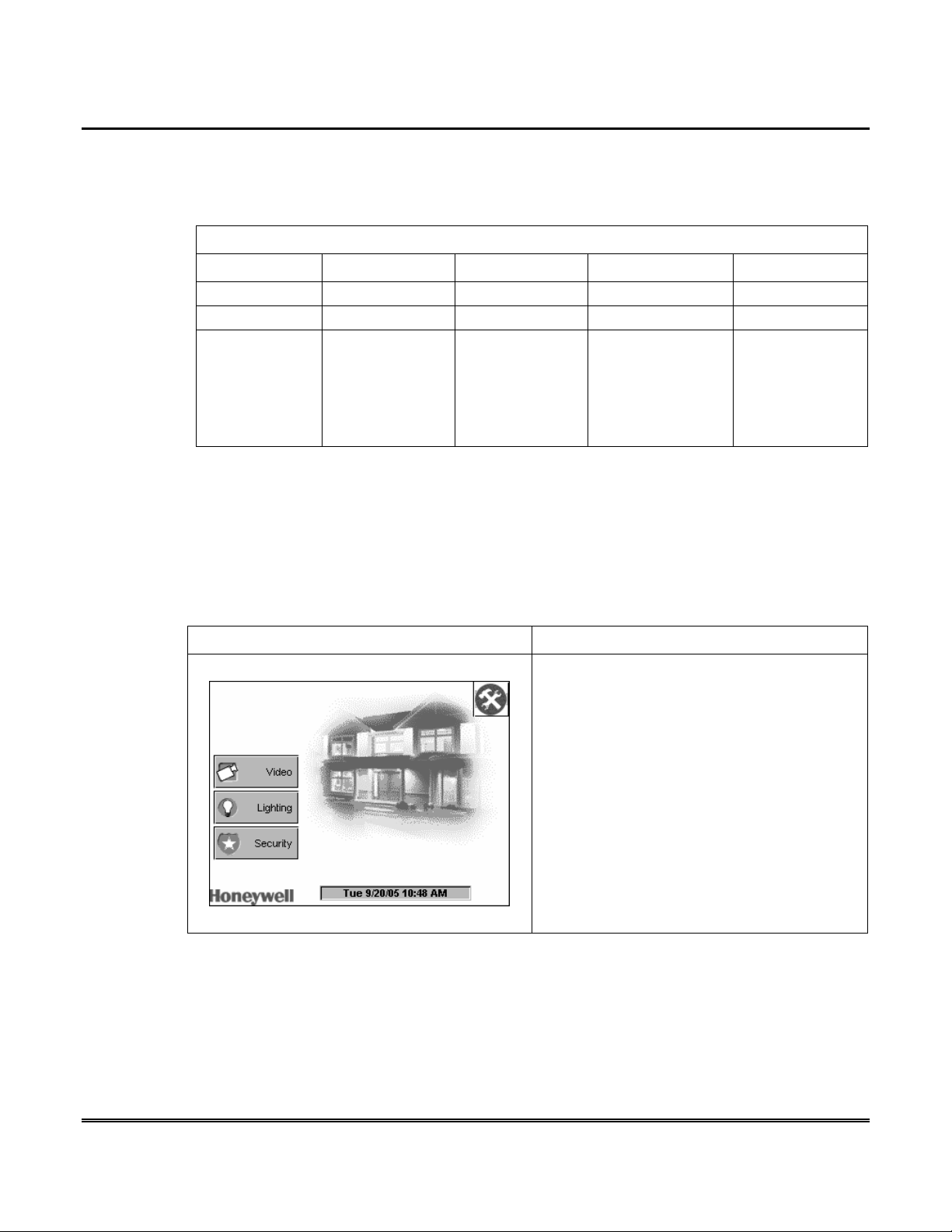
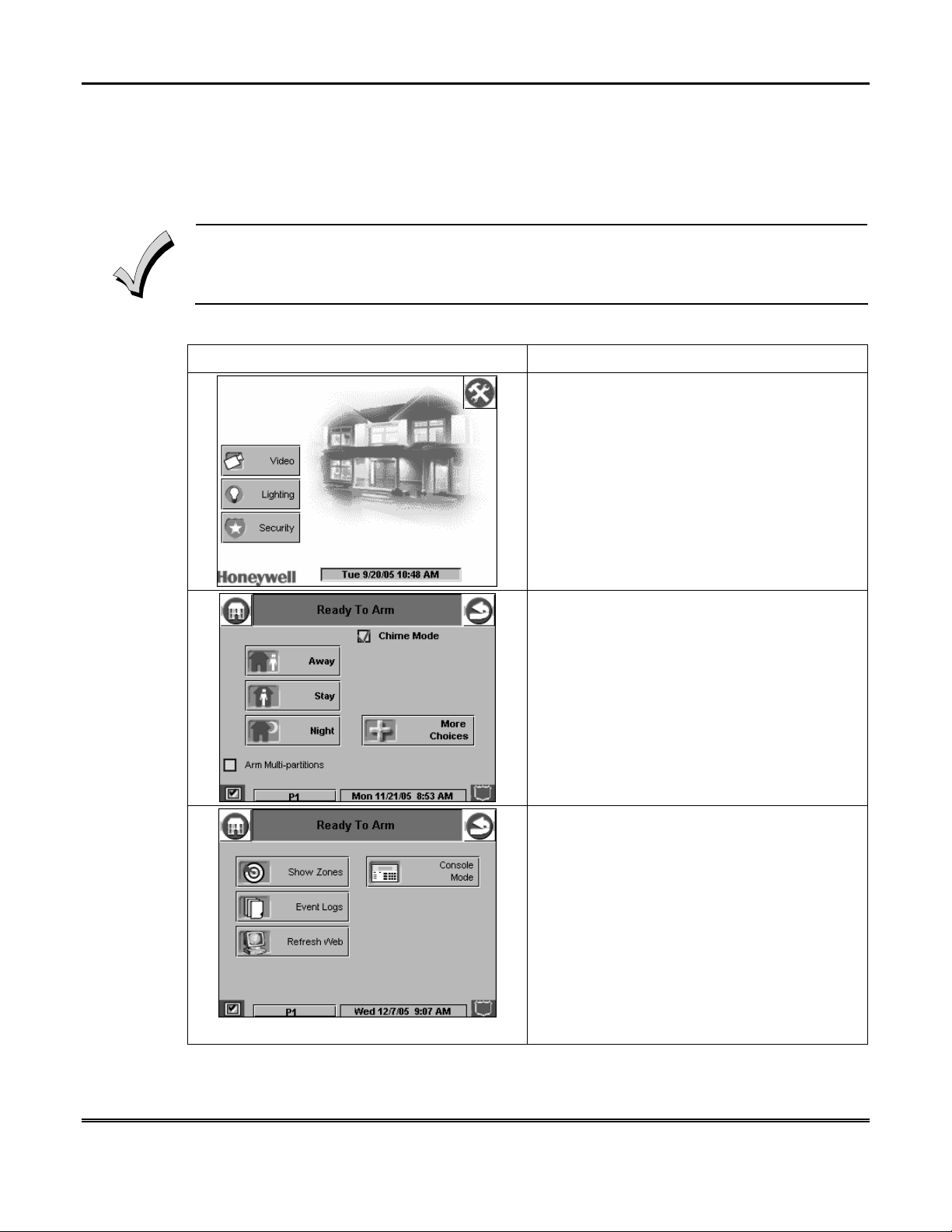
SCREEN ACTION
1. From the "Home" screen, press the
Security button. The "Arming" screen is
displayed.
15
Page 16
Security System Operation (cont'd)
SCREEN ACTION
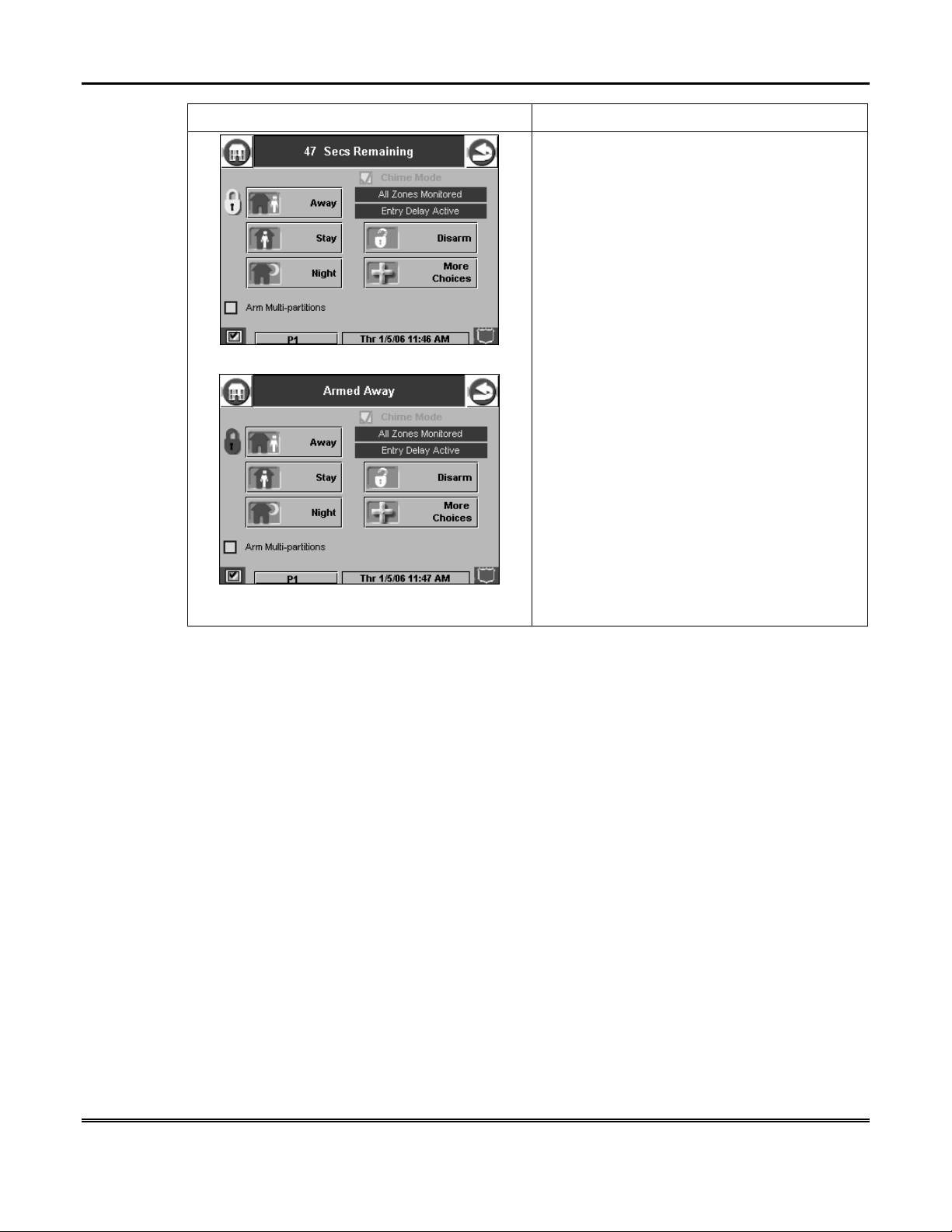
Arming (typical)
Armed (typical)
2. On the "Arming" screen, press the selected
arming button.
o Symphony/Symphony-i beeps twice
(Away and Night Maximum Modes) or
three times (Stay and Night Instant
Modes)
o a Disarm button appears
o a text message appears stating which
zones are arming and whether or not
When exit delay time expires, the screen
automatically changes to indicate the system
is "Armed" and the "lock" next to the pressed
button changes to red. The system is now
armed in the selected mode.
there is an entry delay
o the screen changes to display the
remaining exit delay time, and
o a yellow "lock" appears next to the
pressed button to indicate the system
is arming.
o The exit delay time continues to
decrement to one.
16
Page 17
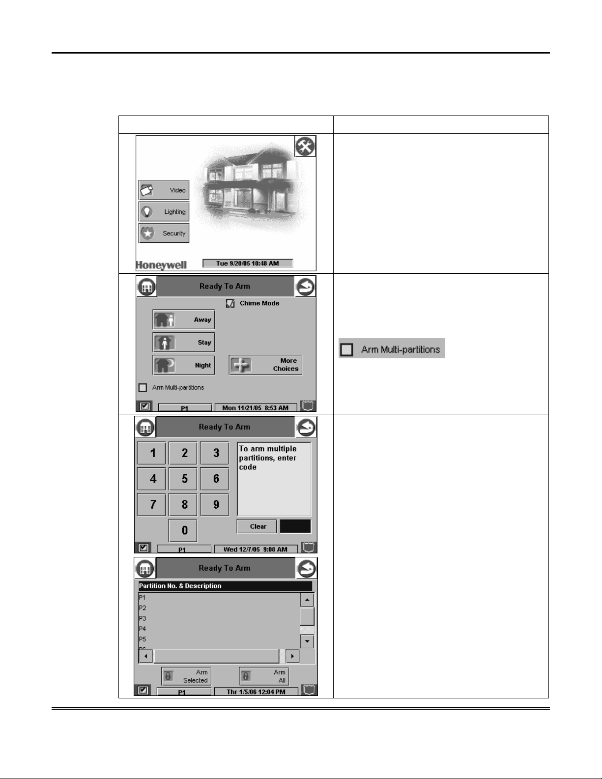
How to Arm Multiple Partitions
To arm multiple partitions:
SCREEN ACTION
Security System Operation (Cont'd)
1. From the "Home" screen press the
Security button to display the "Arming" screen.
2. Press the appropriate arming mode button,
and, when prompted, enter the user code
authorized to access other partition(s).
NOTE: Be sure the Arm Multi-partitions
button is checked.
If the user code is accepted, the system
displays the partitions that the user has access
to.
NOTE: A user may have access to some (but
not all) of the available partitions!
You have two arming options:
To arm one or more partitions, highlight the
partition(s) to be armed by touching it on the
screen, then press Arm Selected.
Press Arm All to arm all available partitions.
17
Page 18
Security System Operation (cont'd)
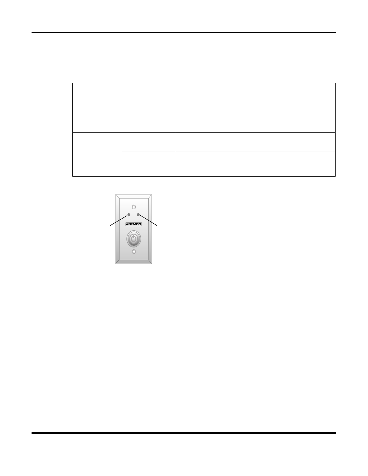
Keyswitch Operation
Your system may be equipped with a keyswitch for arming and disarming a
partition. Red and green lights on the keyswitch plate indicate the status of your
system as follows:
INDICATOR STATUS DESCRIPTION
Green Light
Red Light
On The system is disarmed and ready to be armed (no open
Off If the system is disarmed and the green light is off, it
On Steady System is armed or memory of alarm exists.
Slow Flashing Partition is armed in Away mode.
Rapid Flashing Partition is armed in Stay mode. Memory of alarm,
zones).
indicates the system is not ready (one or more zones are
open).
indicating an alarm has occurred.
GREEN
How to Arm Using a Keyswitch
To arm in the Away mode, turn the key to the right for 1/2 second and release.
Symphony/Symphony-i/Keypads will beep twice and the red light will stay on
steady.
To arm in the Stay mode, turn the key to the right and hold for longer than 3
seconds, then release. Symphony/Symphony-i/Keypads will beep three times and
the red light will flash slowly.
RED
18
Page 19
How to Bypass Zones
The Bypass function is used when you want to arm your system with one or more
zones left open. Bypassed zones are unprotected and will not cause an alarm when
violated while your system is armed.
1. The system will not allow you to bypass fire or emergency zones.
2. To bypass zones, the system must be disarmed first.
To bypass zones do the following:
Security System Operation (Cont'd)
SCREEN ACTION
1. From the "Home" screen, press the
Security button. The "Arming" screen is
displayed.
2. From the "Arming" screen, press the More
Choices button. The "More Choices" screen
is displayed.
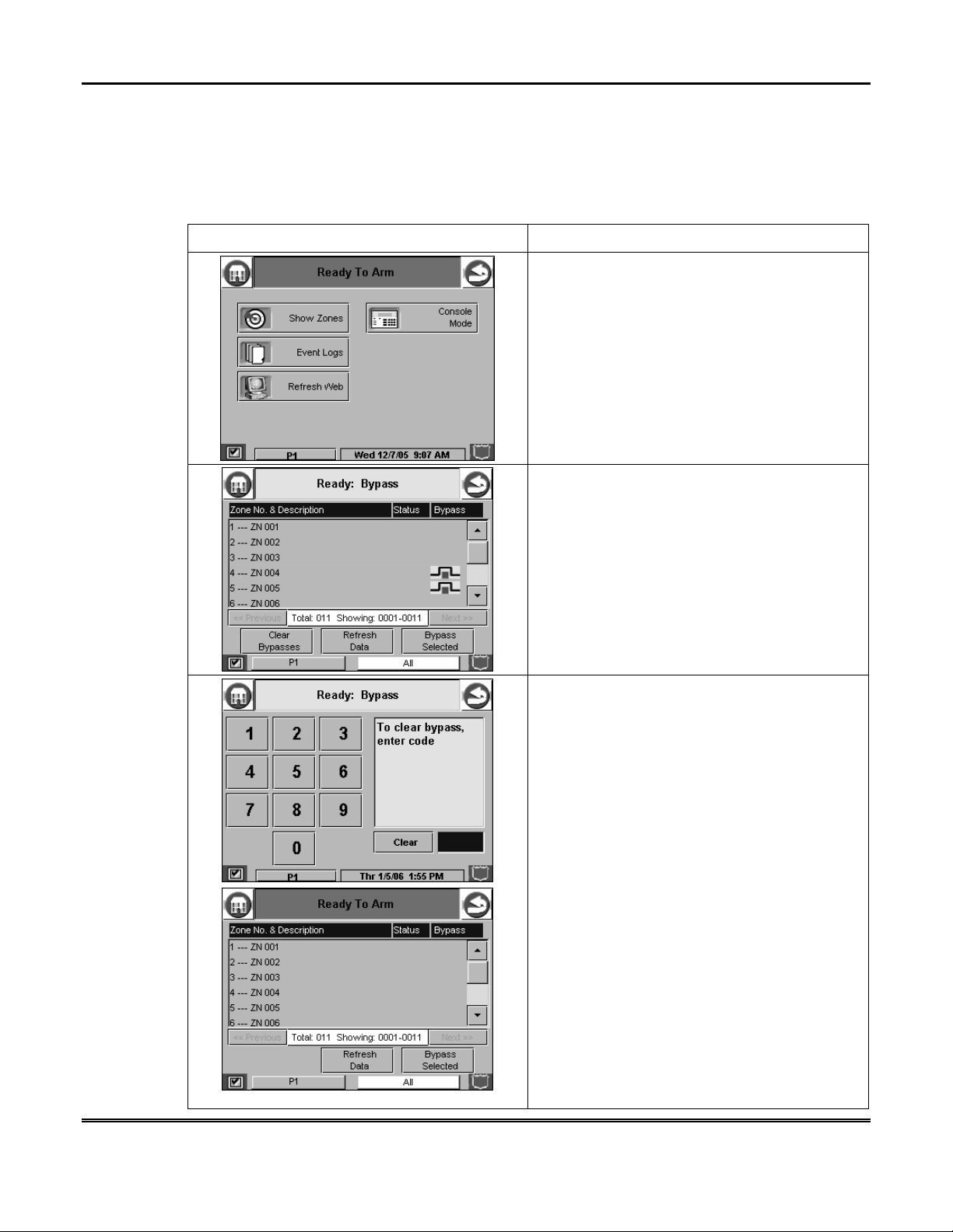
3. Press the Show Zones button on the "More
Choices" screen. The "Zones" screen is
displayed.
19
Page 20

Security System Operation (cont'd)
SCREEN ACTION
4. Highlight the zone(s) to be bypassed by
touching it on the screen when the zones are
displayed.
5. Press the Bypass Selected button. The
"User Authorization" screen is displayed with
the instructions "To bypass, enter code".
6. Enter your 4-digit user code. The "Zones"
screen is displayed showing the system as
Ready: Bypass.
7. From this screen press the “Back” button to
return to the “Arming” screen.
20
Page 21
How to Remove Bypassed Zones
A bypassed zone will automatically be unbypassed when you disarm the system. If
the system is disarmed and a zone is bypassed, you can remove the bypass as
follows:
SCREEN ACTION
Security System Operation (Cont'd)
1. View bypassed zones by pressing the
Show Zones button. The "Zones" screen is
displayed.
2. Remove zone bypasses by pressing the
Clear Bypasses button.
3. The "User Authorization" screen is displayed
with the instructions To clear bypass, enter
code.
NOTE: A zone cannot be unbypassed while
the system is armed.
Enter your 4-digit user code. The "Zones"
screen is displayed showing the system as
Ready to Arm.
NOTE: This will not occur if any zone(s) is
open (not ready).
21
Page 22
Security System Operation (cont'd)
How to Disarm the System
IMPORTANT: If you return and the main burglary sounder is on, DO NOT enter
the premises, but call the police from a nearby safe location. If you return after an
alarm has occurred and the main sounder has shut itself off, Symphony/Symphony-i
will beep rapidly upon entering, indicating that an alarm has occurred during your
absence. LEAVE IMMEDIATELY and CONTACT THE POLICE from a nearby
safe location.
Disarm the system as follows:
SCREEN ACTION
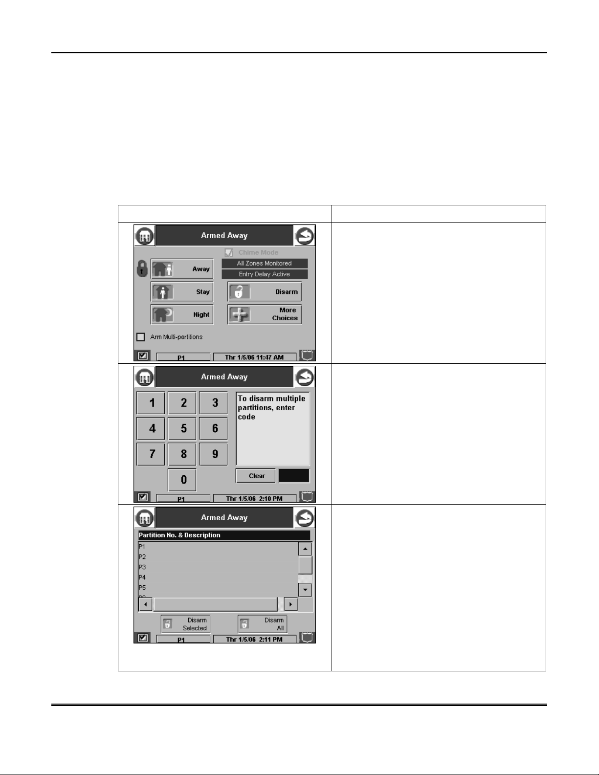
1. Press the Disarm button on any "Armed"
screen. The "User Authorization" screen is
displayed with the instructions “To disarm
multiple partitions, enter code”.
2. Enter your 4-digit user code. The system
will disarm. If you have access to multiple
partitions, the Partition No. & Description
screen is displayed.
3. Press the Disarm All button if you wish to
disarm the system. Symphony/Symphony-i
beeps once and the "Arming" screen is
displayed showing the system as Ready to
Arm or not ready if any zone is faulted (open).
NOTE: If you wish to disarm only selected
partitions, you must first highlight the
partition(s) to be disarmed, then press the
Disarm Selected button.
Symphony/Symphony-i beeps once and the
"Arming" screen is displayed showing the
system as Ready to Arm or not ready if any
zone is faulted (open).
22
Page 23
Security System Operation (Cont'd)
SCREEN ACTION
NOTE: Once the system is disarmed,
Symphony/Symphony-i will return to the
"Home" screen after the selected “To Home
Page After” time has expired. This time is
selected on the “Setup” screen.
23
Page 24
Security System Operation (cont'd)
How to Disarm Using a Keyswitch
To disarm the partition, turn the key to the right and release. If an alarm has
occurred, the red light will be flashing rapidly (memory of alarm).
How to Check the Status of Other Partitions
This system supports between one and eight Partitions (as configured by your
installer.) Partitioning enables a single physical alarm system to control up to eight
areas of protection (partitions) depending on the system you have purchased. Each
Symphony/Symphony-i and Keypad is assigned a default partition for display
purposes, and will show only that partition's information.
For example, if your physical site is a four-apartment housing unit, your alarm
system may be configured with four partitions. Each apartment’s zones (door,
windows, smoke detectors, etc.) are assigned to separate partitions, giving each
apartment independent arming/disarming control of its own partition (area). A
landlord or manager may be granted access to all partitions, so he/she can control
the entire system.
If a user is so authorized, a Symphony/Symphony-i or Keypad in one partition can
be used to perform system functions in another partition. (Note that only those
partitions authorized and programmed by the installer can be accessed in this
manner.)
To check the status of other partitions perform the following:
SCREEN ACTION
1. From the "Home" screen press the
Security button to display the "Arming" screen.
24
Page 25

Security System Operation (Cont'd)
SCREEN ACTION
2. Press the "Current Partition" tab (lower edge
of the screen; in this case it displays P1). The
"User Authorization" screen is displayed with
the instructions “For authorized partitions,
enter code”.
3. Enter the code authorized to access other
partition(s).
If the code is accepted, the system displays
the partitions that user has access to.
NOTE: A code may have access to some (but
not all) of the available partitions.
This screen displays the available partitions (in
this case, Partitions 1 through 8), and their
current status.
The current partition is shown at the top of the
display (in this example, the device is attached
to Partition 1 (P1)). To change this
assignment, select the appropriate button (e.g.
press P2 to switch control to Partition 2).
25
Page 26

Security System Operation (cont'd)
How to Send Emergency Messages
An emergency message for panic or fire can be sent to the central monitoring station
from the Emergency screen. The Emergency screen can be accessed by activating
the "emergency" icon located in the lower-right hand corner of the displayed screen
(see next page for a typical screen).
"EMERGENCY"
ICON
1. The Emergency screen cannot be accessed while running a diagnostic test or the touch
screen calibration. The Emergency screen also cannot be accessed if the user is in an
Internet session.
2. In some instances a pop-up window may be partially covering the "emergency" icon. If this is
the case, you should first close the pop-up window by pressing either the Done or Cancel
button, whichever may be appropriate, on the pop-up screen.
AUI-022-V2
Once the Emergency screen is accessed, perform the following to send an
emergency message.
SCREEN ACTION
On the Emergency screen press and hold (for
at least 2 seconds) the associated alarm
button for the type of emergency message you
want to send (Panic or Fire). When the
message is sent, the associated "Message
Sent" statement is displayed in the text box to
the right of the buttons. You are immediately
returned to the screen from which you pressed
the “Emergency” icon.
26
Page 27

How to View the Event Log
Your system has the ability to record various events in a history log wherein each
event is recorded with the time and date of its occurrence. The control panel must
be programmed to record various system events in installer programming mode.
To view the Event Log, perform the following:
Security System Operation (Cont'd)
SCREEN ACTION
1. From the "Home" screen, press the
Security button. The "Arming" screen is
displayed.
2. From the "Arming" screen press the More
Choices button. The "More Choices" screen is
displayed.
3. Press the Event Logs button on the "More
Choices" screen. The "User Authorization"
screen is displayed with the instructions "Enter
Authorized Code".
27
Page 28

Security System Operation (cont'd)
SCREEN ACTION
4. Enter your “Master” code. The “Event Log”
screen is displayed.
To view additional events, press the up/down
arrows to scroll through the event log. To view
all items, press the Show More button.
NOTE: When All Partitions or All Events
button is pressed, and more than 100 events
exist, the Show More button text will change to
read Next 100.
28
Page 29

Introduction to Fire Alarm System Operation
Your fire alarm system (if installed) is on 24 hours a day, providing continuous
protection. In the event of an emergency, the installed smoke and heat detectors
will automatically send signals to your Control/Communicator, triggering a loud
interrupting sound from the Keypad. An interrupted sound will also be produced by
optional exterior sounders. A FIRE message will appear at your Keypad and
remain on until you silence the alarm.
In Case of Fire Alarm
1. Should you become aware of a fire emergency before your detectors sense the
problem, go to your nearest Keypad and manually initiate an alarm by pressing
the panic key assigned as FIRE emergency (if programmed by the installer) and
hold down for at least 2 seconds.
2. Evacuate all occupants from the premises.
3. If flames and/or smoke are present, leave the premises and notify your local Fire
Department immediately.
Fire Alarm System Operation
If no flames or smoke are apparent, investigate the cause of the alarm. The zone
descriptor of the zone(s) in an alarm condition will appear at the Keypad.
Silencing a Fire Alarm
1. Silence the alarm by entering your code and pressing the OFF key. To clear the
alarm from the display, enter your code and press the OFF key again.
2. If the Keypad does not indicate a READY condition after the second OFF
sequence, press the READY key to display the zone(s) that are faulted. Be sure
to check that smoke detectors are not responding to smoke or heat producing
objects in their vicinity. In this case, eliminate the source of heat or smoke.
3. If this does not remedy the problem, there may still be smoke in the detector.
Clear it by fanning the detector for about 30 seconds.
4. When the problem has been corrected, clear the display by entering your code
and pressing the OFF key.
Fire Display Lock
If several zones produce an alarm before any are silenced, the system can be
programmed to lock the Keypad display with the first zone that produced an alarm.
Ask your installer if your system has been activated with this feature. To display
the other zone(s), press the [✴] key for each zone. Also the “A”, “B”, or “C” key can
be programmed to scroll the Keypad display to view the previous or subsequent fire
alarms.
29
Page 30
Fire Alarm System Operation (cont'd)
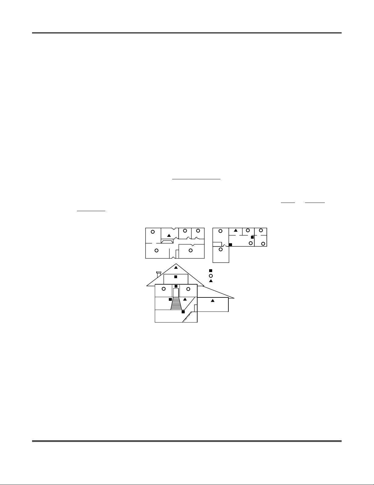
Recommendations for Proper Protection
THE FOLLOWING RECOMMENDATIONS FOR THE LOCATION OF FIRE AND
BURGLARY DETECTION DEVICES HELP PROVIDE PROPER COVERAGE FOR
THE PROTECTED PREMISES.
Recommendations For Smoke And Heat Detectors
With regard to the number and placement of smoke/heat detectors, we subscribe to
the recommendations contained in the National Fire Protection Association's
(NFPA) Standard #72 noted below.
Early warning fire detection is best achieved by the installation of fire detection
equipment in all rooms and areas of the household as follows: For minimum
protection a smoke detector should be installed outside of each separate sleeping
area, and on each additional floor of a multi-floor family living unit, including
basements. The installation of smoke detectors
unfinished), or in garages is not normally recommended.
in kitchens, attics (finished or
For additional protection the NFPA recommends that you install heat
or smoke
detectors in the living room, dining room, bedroom(s), kitchen, hallway(s), attic,
furnace room, utility and storage rooms, basements and attached garages.
DINING
LIVING ROOM
BEDROOM
LVNG RM
BASEMENT
KITCHEN
BEDROOM
TO
BR
BEDROOM
BEDROOM
BEDROOM
KTCHN
BEDROOM
CLOSED
.
DOOR
KITCHEN
TV ROOM
LIVING ROOM
BEDROOM
Smoke Detectors for Minimum Protection
Smoke Detectors for Additional Protection
Heat-Activated Detectors
GARAGE
DINING
BDRM
BDRM
In addition, we recommend the following:
• Install a smoke detector inside every bedroom where a smoker sleeps.
• Install a smoke detector inside every bedroom where someone sleeps with the
door partly or completely closed. Smoke could be blocked by the closed door.
Also, an alarm in the hallway outside may not wake up the sleeper if the door is
closed.
30
• Install a smoke detector inside bedrooms where electrical appliances (such as
portable heaters, air conditioners or humidifiers) are used.
Page 31

Fire Alarm System Operation (Cont'd)
• Install a smoke detector at both ends of a hallway if the hallway is more than 40
feet (12 meters) long.
• Install smoke detectors in any room where an alarm control is located, or in any
room where alarm control connections to an AC source or phone lines are made.
If detectors are not so located, a fire within the room could prevent the control
from reporting a fire or an intrusion.
Recommendations For Proper Intrusion Protection
For proper intrusion coverage, sensors should be located at every possible point of
entry to a home or commercial premises. This would include any skylights that may
be present, and the upper windows in a multi-level building.
In addition, we recommend that radio backup be used in a security system so that
alarm signals can still be sent to the alarm monitoring station in the event that the
telephone lines are out of order (alarm signals are normally sent over the phone
lines, if connected to an alarm monitoring station).
Recommendations for Evacuation
Establish and regularly practice a plan of escape in the event of fire. The following
steps are recommended by the National Fire Protection Association:
1. Position your detector or your interior and/or exterior sounders so that they can
be heard by all occupants.
2. Determine two means of escape from each room. One path of escape should lead
to the door that permits normal exit from the building. The other may be a window,
should your path be impassable. Station an escape ladder at such windows if there
is a long drop to the ground.
3. Sketch a floor plan of the building. Show windows, doors, stairs and rooftops that
can be used to escape. Indicate escape routes for each room. Keep these routes free
from obstruction and post copies of the escape routes in every room.
4. Assure that all bedroom doors are shut while you are asleep. This will prevent
deadly smoke from entering while you escape.
5. Try the door. If the door is hot, check your alternate escape route. If the door is
cool, open it cautiously. Be prepared to slam the door if smoke or heat rushes in.
6. Where smoke is present, crawl on the ground; do not walk upright. Smoke rises
and may overcome you. Clearer air is near the floor.
7. Escape quickly; don't panic.
31
Page 32

Fire Alarm System Operation (cont'd)
8. Establish a common meeting place outdoors, away from your house, where
everyone can meet and then take steps to contact the authorities and account for
those missing. Choose someone to assure that nobody returns to the house — many
die going back.
32
Page 33

Introduction to User Code Setup
Each user must be assigned a name with a corresponding 4-digit user code in order
to gain access to various features and functions. Through Symphony/Symphony-i,
you may program users to access each of the following systems:
• Fire/Burglary
• Internet
Users for the systems are programmed in a central user setup location that provides
the specific questions for the user pertaining to each system. You may want these
users to be the same, but there are situations in which you may want a user to have
access to one system (e.g., Internet) without having access to another (e.g., the
Fire/Burglary system).
How to Access User Setup
Access User Setup as follows:
User Code Setup
SCREEN ACTION
1. From the "Home" screen, press the “Tool
Box” button. The "setup" screen is displayed.
2. Press the User Setup button on the “Setup”
screen. The User Setup screen is displayed.
33
Page 34
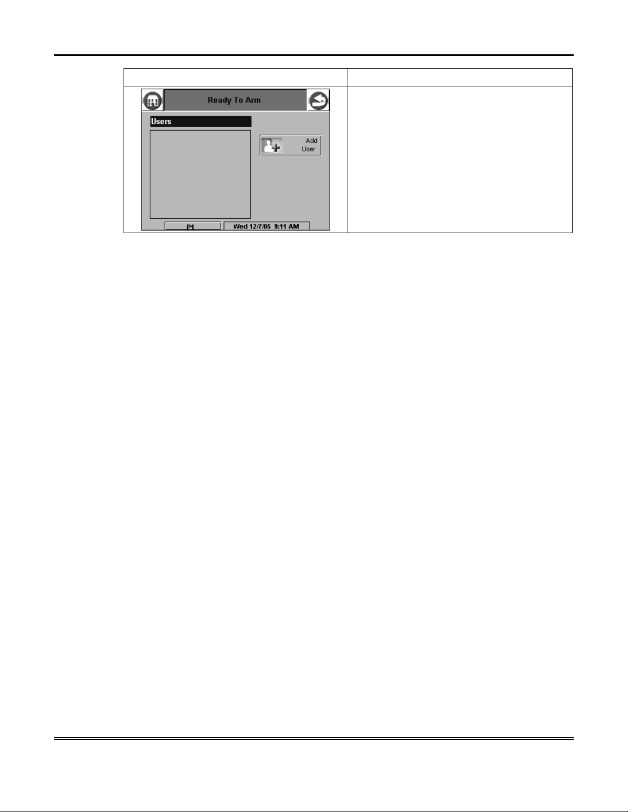
User Code Setup (cont'd)
SCREEN ACTION
34
Page 35

How to Add a User
Add a user as follows:
User Code Setup (Cont'd)
SCREEN ACTION
1. To add a use, press the Add User button.
The "User Authorization" screen is displayed
with the instructions "Enter Authorized Code".
2. Enter your “Master” code. The “User
Options” screen is displayed.
3. Press the box next to Enter User Name.
The Enter Data keyboard screen is displayed.
4. Type in the user name and press the OK
button. The “User Options” screen is displayed
with Enter user code… displayed.
35
Page 36

User Code Setup (cont'd)
SCREEN ACTION
5. Touch the box next to Enter user code.
The "User Authorization" screen is displayed
with the instructions Enter 4 Digits.
6. Enter the 4-digit code for this user. The
“User Options” screen is displayed with the
user’s name and code displayed.
7. Select the partitions and access level for
this user.
NOTE: If this user is to have Internet access,
continue to step 8. If this user is to have
security access only, press the Save button at
this time.
8. Press the Web tab on the “User Options”
screen. The “Web access” screen is
displayed.
36
Page 37

User Code Setup (Cont'd)
SCREEN ACTION
9. To provide this user with Internet access
press the box next to Enable user for web
access until a check appears. You may also
select the Autoswitch to web on disarm
option at this time.
10. Press the Save button. The system will
save the configuration. When the save is
complete, the User Setup screen is displayed
with the new user’s name shown.
37
Page 38

User Code Setup (cont'd)
How to Delete a User
Delete a User as follows:
SCREEN ACTION
1. From the User Setup screen, touch the
user to be deleted. The user name is
highlighted. Press the Delete User button.
The "User Authorization" screen is displayed
with the instructions "Enter Authorized Code".
2. Enter your “Master” code. The Delete
screen is displayed.
3. Press the appropriate button. The User
Setup screen is displayed.
38
Page 39

How to Edit a User
Edit a user as follows:
User Code Setup (Cont'd)
SCREEN ACTION
1. From the User Setup screen, touch the
user to be edited. The user name is
highlighted. Press the Edit User button. The
"User Authorization" screen is displayed with
the instructions "Enter Authorized Code".
2. Enter your “Master” code. The “User
Options” screen is displayed.
3. Select whatever options you wish to select
for this user and press the Save button. The
configuration changes are saved and you are
returned to the User Setup screen.
39
Page 40

User Code Setup (cont'd)
40
Page 41

Introduction to Internet Features
As a household Internet appliance, Symphony/Symphony-i provides access to a
wealth of information, including:
• News
• Sports
• Weather
• E-mail, and
• Live updates of user-selectable content such as your horoscope.
Additionally, you may control all of Symphony/Symphony-i’s functions from any
personal computer or laptop that has Internet capabilities, including security
system functions (arming, disarming, etc.).
Whenever a user is added or edited through the User Setup procedure, if that user
is authorized to have WEB access, upon saving of the user setup information, a
button is automatically generated on the “Home” screen with that user’s name.
Internet Features
Modifying Your WEB Page
You may access and customize your WEB page through your personal computer or
laptop.
To access your existing WEB page go to the Symphony/Symphony-i/AlarmNet web
site at https://Symphony.alarmnet.com.
The screen will prompt,
To access your existing Account, Click here
.
41
Page 42

Internet Features (cont'd)
The screen displays:
Login to personalize your account info.
Account Number
User Name
Password
Submit
Reset
Enter your 12-digit account number (provided by your installer), User Name and
Password and click on the Submit button.
This brings you to the Main Page where you may, by pressing the corresponding
buttons, go to the following screens:
• CONTENT
42
• REMINDERS
• MANAGE USERS
• EDIT PROFILE
• REMOTE CONTROL
• LOGOUT
• Feedback?
You may also click on the corresponding links:
• Click Here
• Click Here
• Click Here
To view your selected stock quotes.
To view your selected Headlines.
To view your E-mail Headers.
Page 43

Internet Features (Cont'd)
Content
Content choices allow you to select additional features that you may want to have
displayed on your console Internet page. When the CONTENT button is clicked on
the main page, the Content screen is displayed. The Content screen contains the
following choices with instructions as to how to select and save your choices.
Content Selections for rick
Content Choices Selected
Stock Quotes
My Email
Horoscopes
US National News
Canadian News
International News
The Sports Network
Sports Scoreboard
AccuWeather
❑
❑
❑
❑
❑
❑
❑
❑
❑
Instructions:
1. Select each item you wish to appear on your console home page by clicking on
the box under the Selected column. A check should appear to indicate this
option is selected.
NOTE: Although all items are selectable, only Stock Quotes, My Email, Horoscopes,
Sports Scoreboard and AccuWeather require user configuration.
2. Click the UPDATE PROFILE button to save your changes.
3. Items requiring additional configuration can be clicked on to configure.
43
Page 44

Internet Features (cont'd)
Stock Quotes
Stock Selections for rick
Enter up to 10 stock ticker symbols separated by commas or spaces.
Use these symbols for Market Indices
Dow Jones Ind. $DJI
NASDAQ Comp COMP
S&P 500 SPX
S&P 100 OEX
CAC-40 (Paris) $CAC
NIKKEI (Tokoyo) $NIKKEI
My Email
To configure your Email option, click on the My Email link. This displays the
“Configure My Email” screen. Simply follow the instructions at the bottom of the
screen.
Username Password Confirm
POP3 Server Name
Instructions:
1. Enter your Email Username. For example, if your email address was
jsmith@Yahoo.com, you would enter jsmith.
44
2. Enter your Email Password and Confirmation.
3. Enter your email POP3 server information. This entry can be found by
contacting your Internet Service Provider. Example for Yahoo is
pop.mail.yahoo.com.
Page 45
Internet Features (Cont'd)
NOTE: Due to their proprietary nature, these email servers are not supported:
®
AOL
, MSN/Hotmail®, and Juno®.
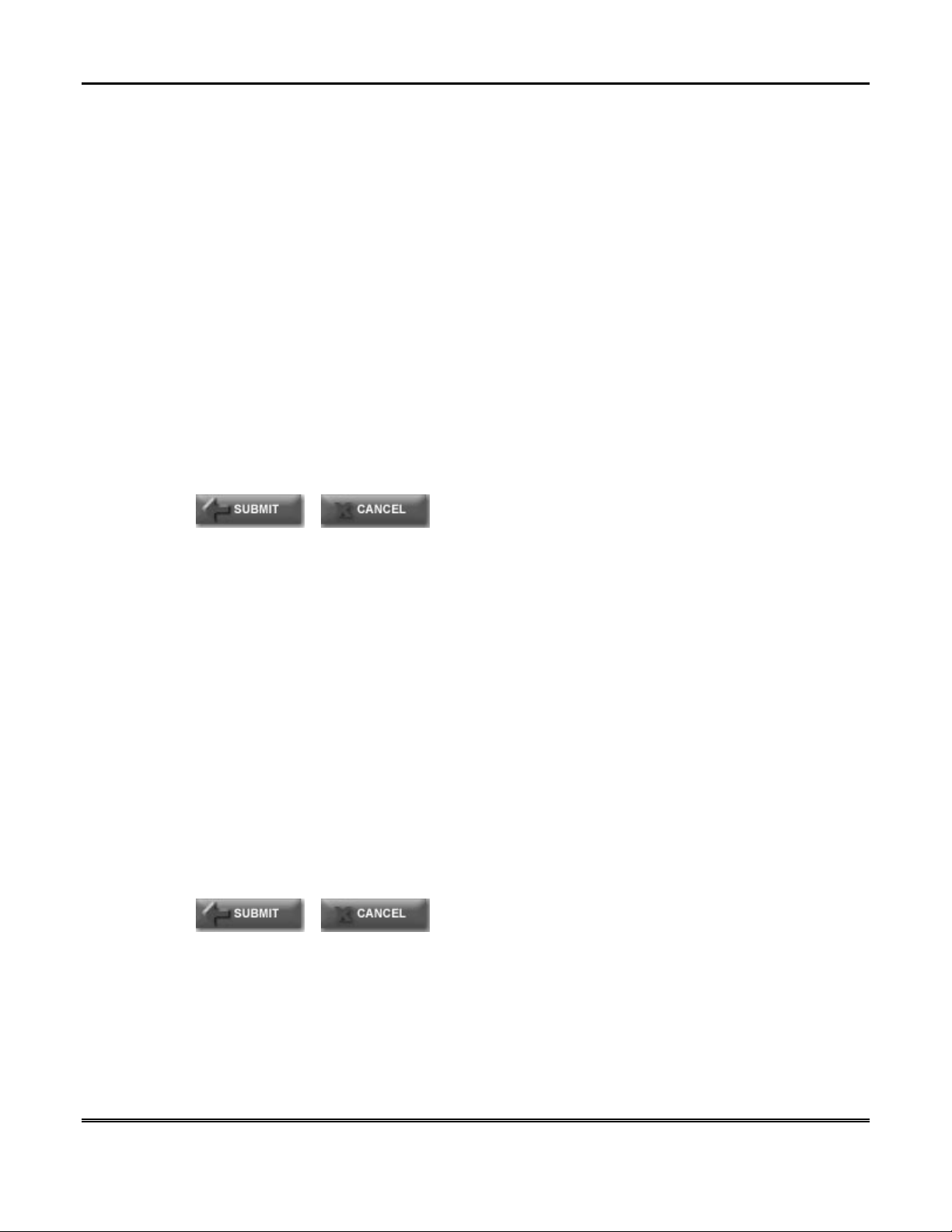
4. Click the SUBMIT button to save your changes. You are automatically
returned to the Content screen.
Horoscopes
To configure your Horoscope option, click on the Horoscope link. This displays the
“Choose My Horoscopes” screen. Simply follow the instructions at the bottom of the
screen.
Aries
Taurus
Gemini
Cancer
Leo
Virgo
❍
❍
❍
❍
❍
❍
Libra
Scorpio
Sagittarius
Capricorn
Aquarius
Pisces
❍
❍
❍
❍
❍
❍
Instructions:
1. Select the single horoscope sign you wish to see on your console Internet page.
2. Click the SUBMIT button to save your changes. You are automatically
returned to the Contents screen.
Sports Scoreboard
Sports Network Scoreboard Selections for rick
❑ Major League Baseball (MLB)
❑ National Football League (NFL)
❑ National Basketball Association (NBA)
❑ National Hockey League (NHL)
1. Select any combination of the sports you wish to see scores from.
2. Click on the Submit button to save your changes.
45
Page 46
Internet Features (cont'd)
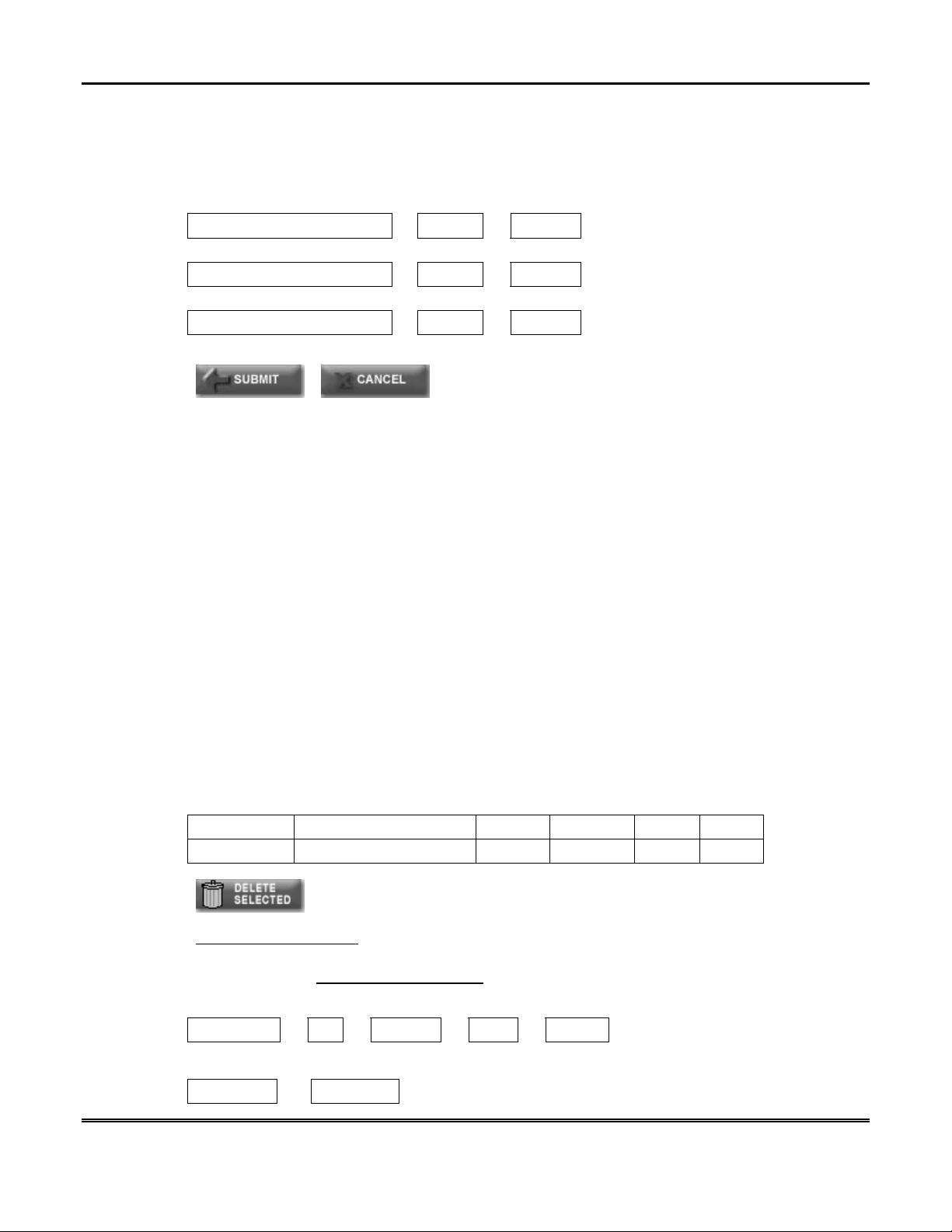
Weather
To configure your Weather option, click on the AccuWeather link. This displays
the “Weather Selections” screen. Simply follow the instructions at the bottom of the
screen.
Edit Clear
Edit Clear
Edit Clear
Instructions:
1. Select up to three city/state choices for weather by clicking the Edit button to
make your selection.
2. Click the Clear button to remove a choice.
NOTE: Your selections will appear on your console Internet page in the order in
which they were selected.
3. Click the Submit button to save your choices.
Reminders
The Reminders function allows you to leave memos on your Symphony/Symphony-i
WEB page so that you won’t forget important events or meetings. When the
REMINDERS button is clicked on the main page, the “Reminder Management”
screen is displayed. The “Reminder Management” screen displays all existing
messages as follows:
Existing Messages
Posted Date Message To User Recurring Priority Select
December 1 Xxxxxx xxx xx xxxxxx rick Yes Urgent
❏
Add a new reminder
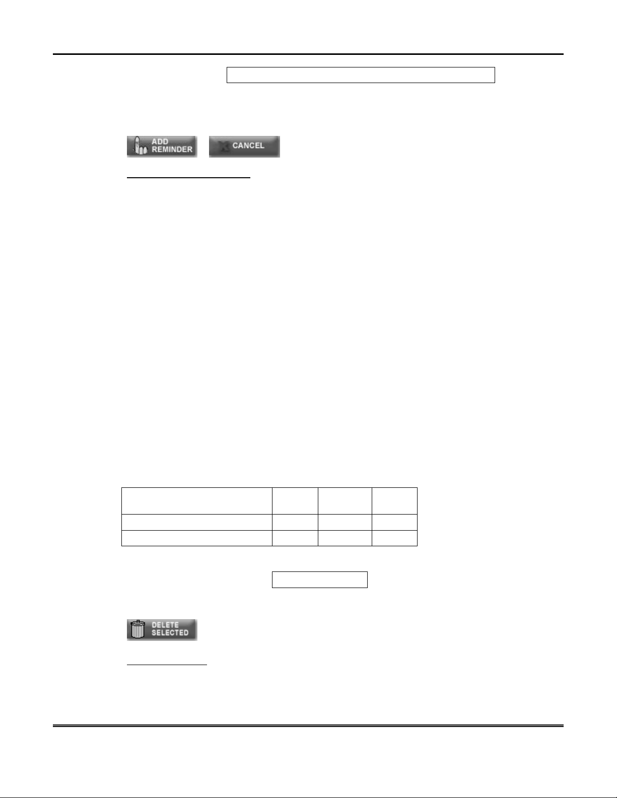
Clicking on the Add a new reminder
Occasion To Month Day Year*
Notify Recurring Priority
❍ Normal ❍ Important ❍ Urgent **
link displays:
46
Page 47
Internet Features (Cont'd)
Message/Reminder
* Year notations are ignored on recurring reminders.
**Urgent Reminders always go to ALL users.
View current reminders
1. By clicking on the boxes for Occasion, To, Month, Day, Year, Notify, and
Recurring, pull down menus are displayed and you may select the option of your
choice. As an example, the Notify pull down menu will allow you to select the Day
of, 1 Day before, 1 Week before, or 2 Weeks before as options to when your
reminder will be displayed on your Symphony/Symphony-i WEB page.
NOTE: No matter what year is selected it is not displayed in current message view.
2. Click on the adjacent circle to select your reminder priority.
IMPORTANT: Your reminder message is limited to 40 characters.
3. Click on the ADD REMINDER button to add this reminder to your Existing
Messages.
Manage Users
The Manage Users function allows you to add and edit users of your
Symphony/Symphony-i WEB page. When the MANAGE USERS button is clicked
on the main page, the “User Management” screen is displayed. This screen displays
all existing users as follows:
Existing Users
User (click to edit the user) Remote
Control
ricky Edit Content Selections No Yes
ringo No Yes
Primary User Name rick
Primary User Password
Enabled Select
❏
❏
(Required for deletion)
Add a new user
To edit a user, click on their user name. The “Edit a User” screen is displayed as
follows:
47
Page 48

Internet Features (cont'd)
Primary User Name rick
Primary User Password
New User Name
New Password
Confirm Password
Remote Control Permission No
User Enabled Yes
Please Note: Leave the Password fields blank unless you are changing the
Password.
To add a new user, click on the Add a New User link. The “Add New User” screen
is displayed as follows:
Primary User Name rick
Primary User Password
New User Name
New Password
Confirm Password
Remote Control Permission No
View current users.
48
Page 49

Internet Features (Cont'd)
Edit Profile
The Edit Profile function allows you (the Master User only) to edit the profile
(password or email address) of a user of your Symphony/Symphony-i WEB page..
When the EDIT PROFILE button is clicked on the main page, the “Edit Profile”
screen is displayed as follows:
Edit User Profile
New User Name rick
New Password *******
Confirm Password *******
Email xxxxxx@xxx.com
Edit the user profile as follows:
1. Enter the user name.
2. Enter the new password.
3. Re-enter (confirm) the new password.
4. Enter the email address.
5. Click on the SAVE button.
Remote Control
The Remote Control function allows you to view and operate your
Symphony/Symphony-i from a remote PC or laptop computer. In remote control
mode you can arm and disarm your system, view zone event log information, and
bypass zones. For accounts that have more than one Symphony/Symphony-i, you
can select which Symphony/Symphony-i is to be accessed by using a radio-button
set. When you click on the REMOTE CONTROL button on the main page, the
“Remote Control” screen is displayed as follows:
Connect via….
49
Page 50

Internet Features (cont'd)
For your protection enter the password for user: [rick]
Password
Start session
Start the Remote Control session as follows:
1. Enter the user’s password.
2. Click on the START SESSION button.
NOTE: If no password is entered or an incorrect password is entered, the screen
will display:
“Failed to Validate User”
Click Try Again To attempt to log in again.
If the password is accepted, the “Remote Control of your Console” screen is shown
with the “Home” screen of your Symphony/Symphony-i displayed.
50
Disconnect
Click on the buttons of the displayed Symphony/Symphony-i screens to operate the
system as you would from the Symphony/Symphony-i Keypad.
When you wish to leave Symphony/Symphony-i, click the Disconnect button.
“Closing, Returning to Remote Control Login.” Is displayed.
Page 51

Internet Features (Cont'd)
User Feedback
User Feedback
Name:
Email Address:
Type of Feedback Suggestion
Category Symphony/Symphony-i Web Interface –
Custom Content
Other:
Comment:
(250 characters max.)
Logout
The LOGOUT button allows you to leave the http://Symphony.alarmnet.com
Internet site. Pressing the LOGOUT button displays the following:
You have been logged out.
Click Here to Close Your Browser
51
Page 52

Internet Features (cont'd)
52
Page 53

Advanced System Features
Introduction to Advanced System Features
While most of the commonly used security functions are available from
Symphony/Symphony-i’s advanced user interface, there are some less used,
advanced features that can either be accessed through Keypad Emulation mode on
the Symphony/Symphony-i or a standard Alpha Keypad. To program your system’s
advanced features, refer to your Control Panel User Guide.
Keypad (Console) Emulation Mode
Console Mode allows you to use a Symphony/Symphony-i interface just as you would
a regular system Keypad. In this mode, you can use either Symphony/Symphony-i’s
touch screen "Keypad,” or the Keypad keys (if available on your model). All
commands shown in Console Emulation mode can also be executed from a standard
Alpha Keypad.
How to Enter Console Emulation Mode
To access the touch screen "Keypad," do the following:
SCREEN ACTION
1. From the "Home" screen, press the
Security button. The "Arming" screen is
displayed.
2. Press the More Choices button. The
"More Choices" screen is displayed.
53
Page 54

Trouble Conditions (Cont'd)
SCREEN ACTION
3. Press the Console Mode button on the
"More Choices" screen. The "Keypad" screen
is displayed.
4. Perform functions as you would from a
regular alpha keypad.
54
Page 55

Summary of Audio Notification
SOUND CAUSE DISPLAY
Loud, Interrupted*
Keypad & External
Loud, Continuous*
Keypad & External
One Short Beep
(not repeated)
Keypad only
One Short Beep
(once every 15
sec.) Keypad only
One Beep
(every 60 sec.)
Keypad only
Two Short Beeps
Keypad only
Three Short Beeps
Keypad only
Rapid Beeping
Keypad only
Slow Beeping
Keypad only
Fire Alarm FIRE is displayed; descriptor of zone in
alarm is displayed.
Burglary/Audible Emergency
Alarm
a. System disarm
b. System arming attempt
with an open zone.
c. Bypass verify
ALARM is displayed; descriptor of zone in
alarm is also displayed.
a. DISARMED/READY TO ARM is
displayed.
b. The number and descriptor of the open
protection zone are displayed.
c. Numbers and descriptors of the
bypassed protection zones are displayed
(One beep is heard for each zone
displayed). Subsequently, the following is
displayed: DISARMED BYPASS Ready to
Arm
System is in test mode Opened Zone identifications will appear.
Low battery at a transmitter LO BAT displayed with description of
transmitter.
Arm Away or Maximum ARMED AWAY or ARMED MAXIMUM is
displayed. Red ARMED indicator is lit.
a. Arm Stay or Instant
b. Zone opened while system
is in Chime Mode.
c. Entry warning**
a. ARMED STAY ZONE BYPASSED or
ARMED INSTANT ZONE BYPASSED is
displayed. Red ARMED indicator is lit.
b. CHIME displayed, descriptor of open
protection zone will be displayed if the [✱]
key is pressed.
c. DISARM SYSTEM OR ALARM WILL
OCCUR is displayed.
a. Trouble
b. AC power loss alert***
c. Memory of alarm
a. CHECK displayed. Descriptor of
troubled protection zone is displayed.
b. AC LOSS displayed (may alternate
with other displays that may be present).
c. FIRE or ALARM is displayed;
descriptor of zone in alarm is displayed.
a. Entry delay warning**
b. Exit delay warning (if
programmed)
a. DISARM SYSTEM OR ALARM WILL
OCCUR is displayed. Exceeding the delay
time without disarming causes alarm.
b. ARMED AWAY or ARMED MAXIMUM
is displayed along with You May Exit Now
* If bell is used as external sounder, fire alarm is pulsed ring; burglary/audible
emergency is steady ring.
55
Page 56

Summary of Audio Notification (Cont'd)
** Entry warning may consist of three short beeps or slow continuous beeping, as
programmed by your installer.
*** Loss of system battery power is not indicated or annunciated by the Keypad
(warnings are for loss of AC power only).
56
Page 57

Summary of Symphony/Symphony-i LED Operation
Symphony/Symphony-i LED Operation
Symphony/Symphony-i has four LEDs labeled - WEB, ARMED, READY and
MESSAGE. WEB and MESSAGE LEDs are yellow. ARMED LED is red and
READY LED is green. Each LED's on and off state has different meanings during
different operations.
Following states use LEDs to represent different sub-states.
• Normal (Idle) State
• Software Download State
• Software Download State - Failure Modes
Each LED can have four different states - ON, OFF, FAST BLINK and SLOW
BLINK. All LEDs do not use all of the above states. Details are provided below.
LEDs During Normal (Idle) State
LED DESCRIPTION
WEB ON – Connected to internet
OFF – not connected
FAST BLINK - either sending or receiving data
SLOW BLINK – connecting to server (BB) or dialing to RAS server (DU)
ARMED ON – Security system is armed
OFF – Security system is not armed
READY ON – Security system is disarmed and ready to arm
OFF – Security system is disarmed but not ready. Faults/troubles present
LEDs During Software Downloading
LED DESCRIPTION
WEB ON – obtained IP address (via either DHCP client or static IP assignment) (BB)
or established link to RAS server (DU)
OFF – not connected
SLOW BLINK – connecting to server (BB) or dialing (DU)
ARMED ON – connected to server
OFF –
FAST BLINK – could not connect to server (no route or authentication failure)
SLOW BLINK – connecting to server
READY ON – successfully downloaded configuration data
FAST BLINK – could not download configuration data or if with ARMED FAST
BLINK then it connected to server but failed authentication
OFF –
MESSAGE ON – erasing application code
SLOW BLINK – downloading application code
VERY SLOW BLINK – verifying CRC after successful code download
57
Page 58

Summary of Symphony/Symphony-i LED Operation (Cont'd)
LED Operation When Software Download Fails
There are the following sequences providing the extra failure information:
1. CRC failure 1 (calculated CRC does not match CRC provided with binary)
• WEB, ARMED, READY and MESSAGE – all FAST BLINK for 3 seconds,
following
• WEB, ARMED, READY and MESSAGE ON for 3 seconds and following
• WEB, ARMED, READY and MESSAGE FAST BLINK for 3 seconds.
2. CRC failure 2 (calculated network CRC does not match CRC provided with
binary)
• WEB, ARMED, READY and MESSAGE – all FAST BLINK for 3 seconds,
following
• WEB, ARMED, READY and MESSAGE SLOW BLINK for 3 seconds and
following
• WEB, ARMED, READY and MESSAGE FAST BLINK for 3 seconds.
58
Page 59

Symphony/Symphony-i Setup
How to Access Symphony/Symphony-i Setup Options
Setup allows you to adjust the touch screen contrast and/or adjust the
Symphony/Symphony-i speaker volume. You may also select the time interval that
must pass prior to Symphony/Symphony-i going into screen saver mode (screen goes
blank). Additionally, you may enter the User Setup screen, Advanced Setup
screen, or Clean Screen (maintenance mode) from the "Setup" screen by pressing
the corresponding button.
How to Access Setup
Access the "Setup" features as follows:
SCREEN ACTION
1. From the "Home" screen, press the “Tool
box” button. The "Setup" screen is displayed.
59
Page 60
Symphony/Symphony-i Setup (cont'd)
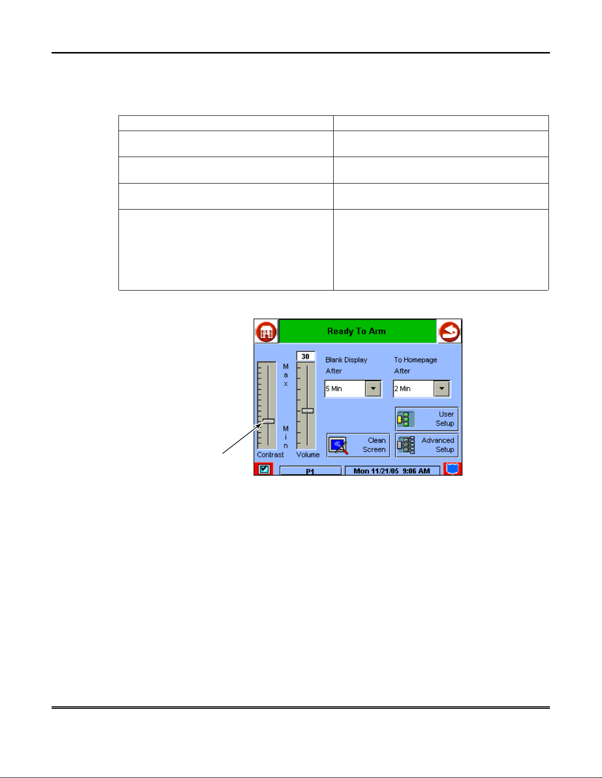
How to Adjust the Touch Screen Contrast
You may adjust the touch screen contrast as follows:
If… Then…
you want to increase contrast move the slide bar above the current contrast
you want to decrease contrast move the slide bar below the current contrast
another adjustment or selection is to be made go to the corresponding paragraph in this
no additional adjustment or selection is to be
made
setting.
setting.
section.
press the "Back" icon at the upper-right-hand
corner of the "Setup" screen to return to the
previous screen, or
press the "Home" icon in the upper left-hand
corner of the "Setup" screen to return to your
"Home" screen.
60
CONTRAST
SLIDEBAR
INDICATOR
AUI-011-V1
Touch Screen Contrast Control
Page 61
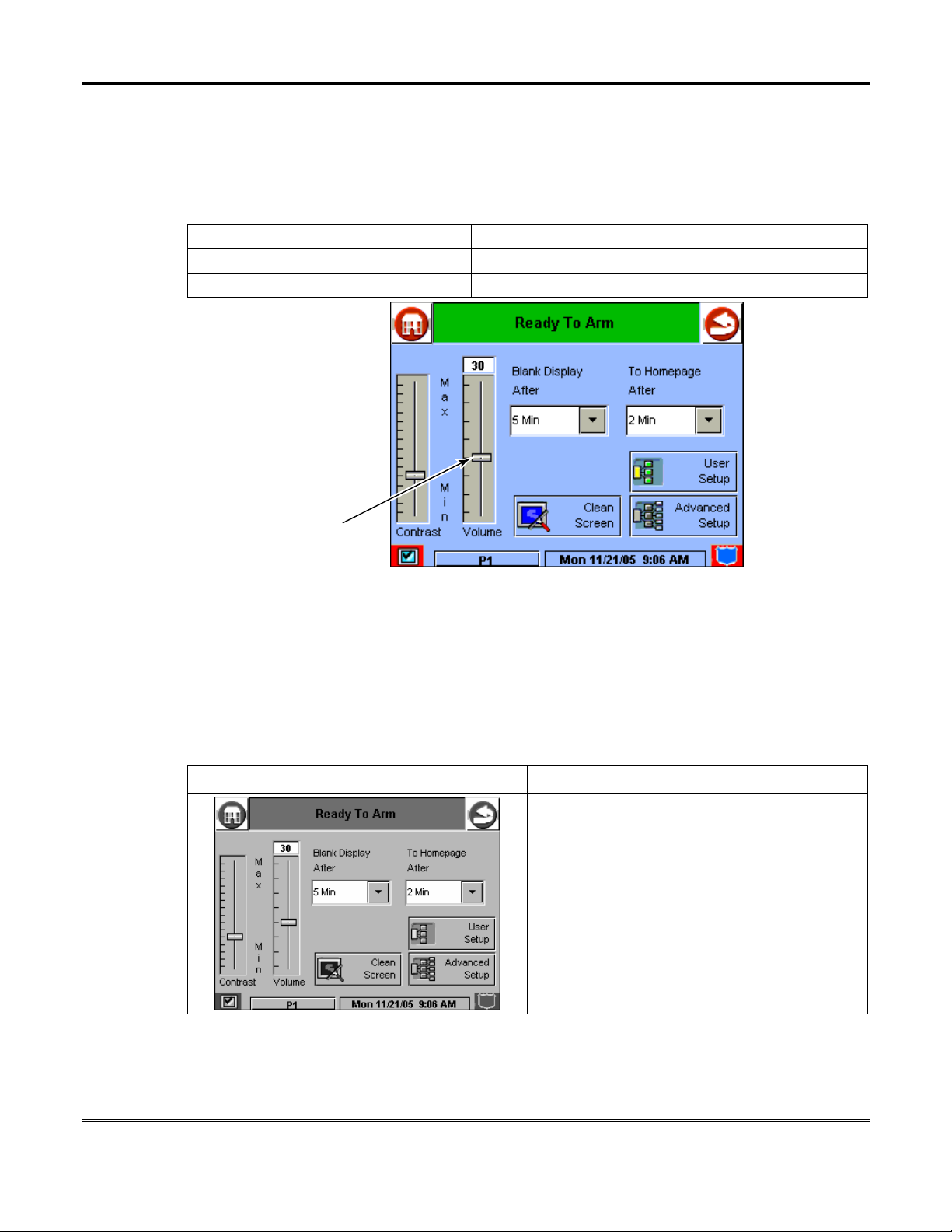
How to Adjust the Volume
You may adjust the Symphony/Symphony-i speaker volume by pressing your finger
on the touch screen slide bar associated with the "Volume" scale and doing the
following:
If… Then…
you want to increase volume move the slide bar above the current volume setting.
you want to decrease volume move the slide bar below the current volume setting.
Symphony/Symphony-i Setup (Cont'd)
VOLUME
SLIDEBAR
INDICATOR
Symphony/Symphony-i Volume Control
How to Select Screen Saver Activation Time
When Symphony/Symphony-i is not armed and not active, it will automatically go
into screen saver mode (display goes blank) after the selected blank display time
has expired (unless never option is selected). To select the screen blank time, do the
following:
SCREEN ACTION
AUI-019-V1
1. On the "Setup" screen, press the Blank
Display After: "arrow" button. A pop-up
window displaying the time period options is
displayed.
61
Page 62

Symphony/Symphony-i Setup (cont'd)
SCREEN ACTION
2. Select the time period option you want by
pressing it. The pop-up window closes
automatically and the selection is displayed in
blue.
NOTE: Additional options can be viewed by
using the up/down "arrows" to scroll through
the time period options.
3. Press either the "Home" or "Back" icon. A
Keypad Profile pop-up window is displayed
stating “Saving Profile.. Please Wait When
the Profile update is complete,
Symphony/Symphony-i goes to the "Home"
screen or "More Choices" screen, depending
on whether you pressed the "Home" or "Back"
icon ("Home" screen shown).
62
Page 63
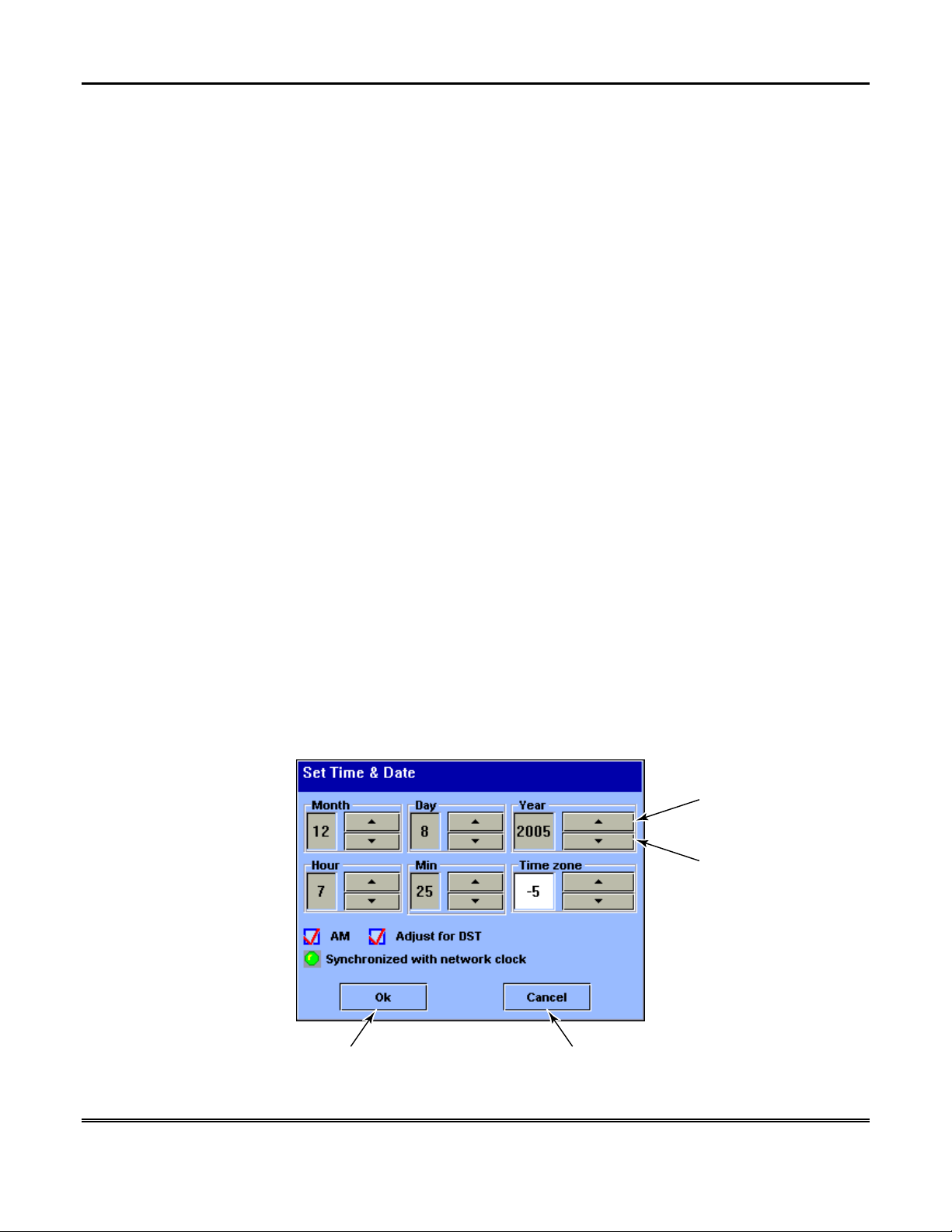
How to Set the Time and Date
You can set the time and date from the Set Time & Date screen. This screen can
be accessed by pressing the Time and Date bar located at the bottom of each
Symphony/Symphony-i screen.
• Since Synchronized with network clock is always selected on the Set Time
& Date screen, whenever Symphony/Symphony-i checks in with the server
(every 10 seconds) it will get the current GMT time. If the
Symphony/Symphony-i time differs from GMT by 10 seconds or more, the
Symphony/Symphony-i time will be reset. Additionally, Symphony/Symphony-i
will send time to the control panel every hour. This 1-hour timer starts on
Symphony/Symphony-i power-up.
• Daylight Savings Time is processed internal to the Symphony/Symphony-i, since
Symphony/Symphony-i gets GMT from the server. When Symphony/Symphony-i
adjusts for DST, the next time the 1-hour timer expires, the new value should be
sent to the control panel.
IMPORTANT: This means that the Symphony/Symphony-i setting will override
and overwrite the control panel time setting. That is, if the control panel is set for
DST and adjusts but Symphony/Symphony-i is not, upon the 1-hour timer
expiration, the control panel will be updated to the current Symphony/Symphony-i
time that is not adjusted for DST.
Symphony/Symphony-i Setup (Cont'd)
Refer to the Time Zones Settings chart (on the following page) to select the
corresponding Time zone for the location of the Symphony/Symphony-i by pressing
the “increase” or “decrease” arrow buttons.
Adjust either or both the time and date by pressing the “increase” or “decrease”
arrow buttons as necessary until the proper month, day, year, hour, and minute are
displayed.
INCREASE
BUTTON
(TYPICAL)
DECREASE
BUTTON
(TYPICAL)
OK
BUTTON
CANCEL
BUTTON
AUI-009-V1
Set Time & Date Screen
63
Page 64

Symphony/Symphony-i Setup (cont'd)
Time Zones
Using the chart below, select the time zone number corresponding to the location of
the installation
.
Time Zone Settings
L
M Y
L
K
I
H
G
E
C D F
B
A
Z
N
O
P
Q
R
S
T
U
V
W
X
Y
M
International Date Line
M
L
K
K
I
X
L
I
I
I
M
M
K
K
H
H
H
H
H
G
F
F
E
D
D
*
E
D
D
*
D
C
B
B
B
A
A
A
Z
Z
Z
N
‡
Q
P
Q
R
S
S
T
T
Z
N
P*
R
S
G
*
F
*
E
F
F
*
E
*
E
E
E
D
C
C
C
C
B
A
Z
Z
N
P
Q
R
R
S
U
V
†
W
X
International Date Line
M
M
M*
M
*
M
M
L
L
L
K
I
I
H
G
G
*
F
E
D
C
B
A
A
Z
O
P
Q
S
*
V
W
W
X
M
L
M
*
L
*
K
K
I*
H
D
C
B
Z
O
M
K
m
hh
− 7
− 8
TUU*VV*WX
m
h
− 1
− 2
NOPP*QRS
m
h
+10
+10 30
KK*LL*MM*M†
m
h
+ 5 30
+ 6
E*FF*GHII*
Standard Time = Universal Time + value from table
m
0
+ 1
ZABCC*DD*
O
Q
− 8 30
− 9
− 3
− 3 30
+11
+11 30
+ 6 30
+ 7
+ 2
+ 3
− 9 30
−10
− 4
− 5
+12
+13
+ 8
+ 9
+ 3 30
+ 4
P
Q
‡
−11
−12
Y
− 6
+14
+ 9 30
+ 4 30
+ 5
E
180
150E
120E
90E
60E
No Standard Time legally adopted
‡
30E
0
30W
60W
P
90W
S
U
W
Corrected to June 2000
*
M
M
STANDARD TIME ZONES
Time, is kept in some places
Zone boundaries are approximate
Daylight Saving Time (Summer Time),
usually one hour in advance of Standard
120W
150W
Map outline © Mountain High Maps
Compiled by HM Nautical Almanac Office
180
64
Page 65

How to Calibrate the Touch Screen
Calibrate the touch screen as follows:
SCREEN ACTION
Symphony/Symphony-i Setup (Cont'd)
1. From the "Home" screen, press the “Tool
Box” button. The "Setup" screen is displayed.
4. Press the Advanced Setup button on the
"Setup" screen. The "User Authorization"
screen is displayed with the instructions "Enter
Authorized Code".
5. Enter your “Master” code. The “Advanced
Setup” screen is displayed.
6. Press the Diagnostics button on the
"Advanced Setup" menu screen. The
"Diagnostics" screen is displayed.
65
Page 66

Symphony/Symphony-i Setup (cont'd)
SCREEN ACTION
7. Begin the Touchscreen calibration from the
"Diagnostics" screen by pressing the
Calibrate button. When the Calibrate button is
pressed, the Touch Screen Calibration
screen is displayed.
8. Within the Touch Screen Calibration
screen you are asked to Press the center of
the box in upper left corner. Press the center
of the square.
When this square is touched, the Touch
Screen Calibration screen displays Next
press the box in the upper right corner.
9. Press the center of the square. The Touch
Screen Calibration screen displays Next
press the box in lower right corner.
66
Page 67

Symphony/Symphony-i Setup (Cont'd)
SCREEN ACTION
10. Press the center of the square. The Touch
Screen Calibration screen displays Next
press the box in lower left corner.
11. Press the center of the square. The
Touch Screen Calibration screen displays
Touch target to verify calibration.
If touch screen calibration was not successful,
Calibration Unsuccessful is displayed
momentarily. You are then returned
automatically to the first Touch Screen
Calibration screen.
NOTE: You will progress through the Touch
Screen Calibration screens regardless of
where you touch. To successfully calibrate the
touch screen, you must press the center of the
box on each screen.
67
Page 68

Symphony/Symphony-i Setup (cont'd)
68
Page 69

Replacing Batteries In Wireless Sensors
Wireless sensors may not have been used in your security system.
If your system has wireless sensors, each wireless sensor in your system has a 9volt or 3-volt battery. The system detects a low battery in any wireless sensor,
including smoke detectors, the optional personal emergency transmitter, and the
optional portable wireless Keypad. (A low battery in a portable wireless Keypad is
detected as soon as one of its keys is pressed, and the Keypad will display 00.)
Alkaline batteries provide a minimum of 1 year of operation, and in most units and
applications, provide 2 to 4 years of service. Actual battery life will depend on the
environment in which the sensor is used, the number of signals that the transmitter
in the sensor has had to send, and the specific type of sensor. Factors such as
humidity, high or low temperatures or large swings in temperature, may lead to the
reduction of battery life in an installation. If you have a low battery in a wireless
sensor, a low battery message is displayed on the Keypad.
Maintaining Your System
In addition, a battery-operated smoke detector with a low battery also emits a single
"chirp" sound once every 20 to 30 seconds, identifying itself as the smoke detector
with the weak battery. If you do not replace a smoke detector's low battery, the
smoke detector may sound continuously, as if there were a fire alarm.
The low battery message comes on as a warning that battery replacement in indicated
sensor(s) is due within 30 days. In the meantime, the sensor(s) causing the low battery
indication is still fully operational.
Important: Use only batteries recommended by your installer as replacement.
Silencing Low Battery Warning Tones at the Keypad
The warning tones can be silenced by performing an OFF sequence (code plus OFF
key), but the low battery display remains on as a reminder that you have a low
battery condition in one or more of your sensors. When you replace the battery, the
sensor sends a "good battery" signal to the panel as soon as the sensor is activated
(opening/closing of door, window, etc.), causing the low battery display to turn off. If
the sensor is not activated, the display automatically clears within 1 hour.
69
Page 70
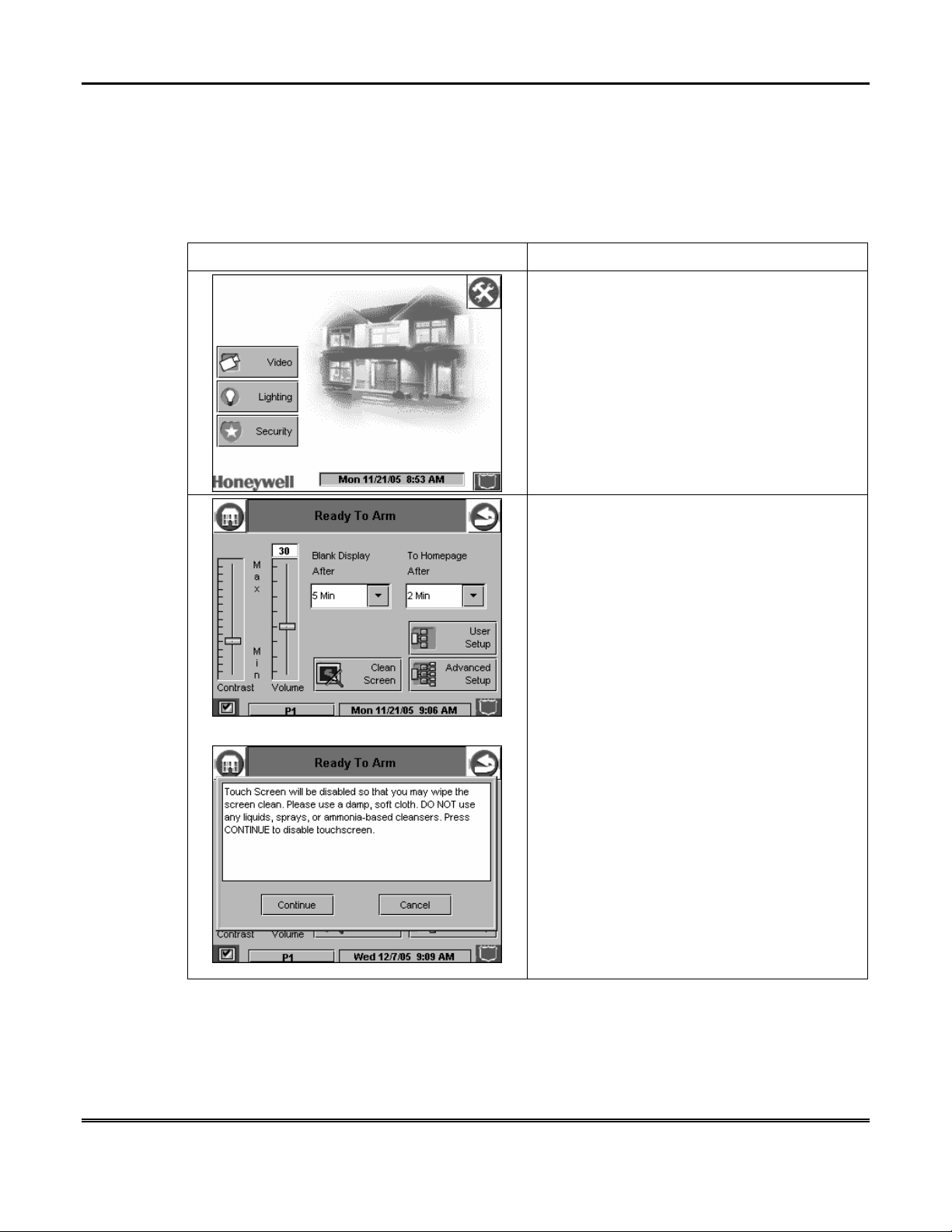
Maintaining Your System (cont'd)
How to Clean your Symphony/Symphony-i
IMPORTANT: Do not use an abrasive cleaning agent or abrasive cloth when
cleaning your Symphony/Symphony-i or damage to the touch screen may occur.
Clean Symphony/Symphony-i as follows:
SCREEN ACTION
1. From the "Home" screen, press the “Tool
Box” button. The “Setup” screen is displayed.
4. Press the Clean Screen button. A window
indicating “Touch Screen will be disabled so
that you may wipe the screen clean. Please
use a damp, soft cloth. DO NOT use any
liquids, sprays, or ammonia-based
cleansers. Press CONTINUE to disable
touchscreen.”
When the Continue button is pressed the
“Touch Screen Disabled for ➙➙➙➙ 30 Seconds”.
During these 30 seconds the touch screen
should be wiped clean of fingerprints using a
mild soap solution and a soft cloth. When the
counter reaches zero, the window
automatically closes and the touch screen is
active.
NOTE: Do not spray cleaning agent directly on
the screen, spray it on cloth, then wipe surface
area.
70
Page 71

Routine Care
Maintaining Your System (Cont'd)
SCREEN ACTION
• Treat the components of your security system as you would any other electrical
equipment. Do not slam sensor-protected doors or windows.
• Keep dust from accumulating on the Keypad and all protective sensors,
particularly on motion sensors and smoke detectors.
The Keypad and sensors should be cleaned carefully with a dry soft cloth. Do not
spray water or any other fluid on the units.
71
Page 72

Maintaining Your System (cont'd)
72
Page 73

Glossary
The following terms are used throughout the guide.
Arm/Disarm: “Armed” simply means that the burglary portion of your system is
turned ON and is in a state of readiness. “Disarmed” means that the burglary
system is turned OFF, and must be rearmed to become operational. However, even
in a “disarmed” state, “emergency” and “fire” portions of your system are still
operational.
Bypass: To intentionally leave a specific zone unprotected while the rest of the
system is armed.
Day/Night Zone: An area of protection whose violation causes a trouble indication
during the disarmed (DAY) mode and an alarm during the armed (NIGHT) mode.
Delay Zone: An area of protection containing doors most frequently used to enter
or exit (typically, a front door, back door, or door from the garage into the building).
The delay zone allows sufficient time for authorized entry or exit without causing an
alarm. Consult your installer for the entry and exit delay times that have been set
for your system during installation and record them on the separate sheet provided
in this guide.
Keypad: This is the device through which you operate your system. It contains
numbered pushbuttons similar to those on telephones or calculators. These keys
control the arming or disarming of the system, and perform other functions that
were previously described in this manual.
Master Code: A 4-digit code that gives users access to all of the system’s functions,
including the ability to program other users in the system. See also “User Code.
Partition: An independent group of zones that can be armed and disarmed without
affecting other zones or users.
User Code: A 4-digit code that gives users access to the system’s basic functions.
See also “Master Code.”
Zone: A specific protection point (e.g., door or window).
73
Page 74

Glossary (Cont'd)
74
Page 75

UL NOTICE: This is a “GRADE A” system.
“FEDERAL COMMUNICATIONS COMMISSION (FCC) Part 15 STATEMENT”
This equipment has been tested to FCC requirements and has been found acceptable for use. The FCC requires
the following statement for your information:
This equipment generates and uses radio frequency energy and if not installed and used properly, that is, in strict
accordance with the manufacturer’s instructions, may cause interference to radio and television reception. It has
been type tested and found to comply with the limits for a Class B computing device in accordance with the
specifications in Part 15 of FCC Rules, which are designed to provide reasonable protection against such
interference in a residential installation. However, there is no guarantee that interference will not occur in a
particular installation. If this equipment does cause interference to radio or television reception, which can be
determined by turning the equipment off and on, the user is encouraged to try to correct the interference by one or
more of the following measures:
• If using an indoor antenna, have a quality outdoor antenna installed.
• Reorient the receiving antenna until interference is reduced or eliminated.
• Move the receiver away from the control/communicator.
• Move the antenna leads away from any wire runs to the control/communicator.
• Plug the control/communicator into a different outlet so that it and the receiver are on different branch
circuits.
If necessary, the user should consult the dealer or an experienced radio/television technician for additional
suggestions.
The user or installer may find the following booklet prepared by the Federal Communications Commission helpful:
“Interference Handbook”
This booklet is available from the U.S. Government Printing Office, W ashington, DC 20402.
The user shall not make any changes or modifications to the equipment unless authorized by the Installation
Instructions or User’s Manual. Unauthorized changes or modifications could void the user’s authority to operate
the equipment.
IN THE EVENT OF TELEPHONE OPERATIONAL PROBLEMS
In the event of telephone operational problems, disconnect the control by removing the plug from the RJ31X
(CA38A in Canada) telephone wall jack. We recommend that your certified installer demonstrate disconnecting the
phones on installation of the system. Do not disconnect the phone connection inside the control/communicator.
Doing so will result in the loss of your phone lines. If the regular phone works correctly after the
control/communicator has been disconnected from the phone lines, the control/communicator has a problem and
should be returned for repair. If upon disconnection of the control/communicator, there is still a problem on the
line, notify the telephone company that they have a problem and request prompt repair service. The user may not
under any circumstances (in or out of warranty) attempt any service or repairs to the system. It must be returned to
the factory or an authorized service agency for all repairs.
75
Page 76

FEDERAL COMMUNICATIONS COMMISSION (FCC) Part 68 NOTICE
This equipment complies with Part 68 of the FCC rules. On the front cover of this equipment is a label that
contains, among other information, the FCC registration number and ringer equivalence number (REN) for this
equipment. If requested, this information must be provided to the telephone company.
This equipment uses the following jacks:
An RJ31X is used to connect this equipment to the telephone network.
The REN is used to determine the quantity of devices that may be connected to the telephone line. Excessive
RENs on the telephone line may result in the devices not ringing in response to an incoming call. In most, but not
all areas, the sum of the RENs should not exceed five (5.0). To be certain of the number of devices that may be
connected to the line, as determined by the total RENs, contact the telephone company to determine the
maximum REN for the calling area.
If this equipment causes harm to the telephone network, the telephone company will notify you in advance that
temporary discontinuance of service may be required. If advance notice is not practical, the telephone company
will notify the customer as soon as possible. Also, you will be advised of your right to file a complaint with the FCC
if you believe necessary.
The telephone company may make changes in its facilities, equipment, operations, or procedures that could affect
the operation of the equipment. If this happens, the telephone company will provide advance notice in order for
you to make the necessary modifications in order to maintain uninterrupted service.
If trouble is experienced with this equipment, please contact the manufacturer for repair and warranty information.
If the trouble is causing harm to the telephone network, the telephone company may request you remove the
equipment from the network until the problem is resolved.
There are no user serviceable components in this product, and the manufacturer must make all necessary repairs.
Other repair methods may invalidate the FCC registration on this product.
This equipment cannot be used on telephone company-provided coin service. Connection to Party Line Service is
subject to state tariffs.
This equipment is hearing-aid compatible.
When programming or making test calls to an emergency number, briefly explain to the dispatcher the reason for
the call. Perform such activities in the off-peak hours; such as early morning or late evening.
76
Page 77

CANADIAN DEPARTMENT OF COMMUNICATIONS (DOC) STATEMENT
NOTICE
The Canadian Department of Communications label
identifies certified equipment. This certification means that
the equipment meets certain telecommunications network
protective, operational and safety requirements. The
Department does not guarantee the equipment will
operate to the user’s satisfaction.
Before installing this equipment, users should ensure that
it is permissible to be connected to the facilities of the
local telecommunications company. The equipment must
also be installed using an acceptable method of
connection. In some cases, the company’s inside wiring
associated with a single line individual service may be
extended by means of certified connector assembly
(telephone extension cord). The customer should be
aware that compliance with the above conditions may not
prevent degradation of service in some situations.
Repairs to certified equipment should be made by an
authorized Canadian maintenance facility designated by
the supplier. Any repairs or alterations made by the user
to this equipment, or equipment malfunctions, may give
the telecommunications company cause to request the
user to disconnect the equipment.
Users should ensure for their own protection that the
electrical ground connections of the power utility,
telephone lines and internal metallic water pipe system, if
present, are connected together. This precaution may be
particularly important in rural areas.
Caution: User should not attempt to make such
connections themselves, but should contact the
appropriate electric inspection authority, or electrician, as
appropriate.
The Load Number
denotes the percentage of the total load to be connected
to a telephone loop which is used by the device, to
prevent overloading. The termination on a loop may
consist of any combination of devices subject only to the
requirement that the total of the Load Numbers of all the
devices does not exceed 100.
(LN) assigned to each terminal device
L’étiquette du ministère des Communications du Canada
identifie le matériel homologué. Cette étiquette certifie que le
matériel est conforme à certaines normes de protection,
d’exploitation et de sécurité des réseaux de
télécommunications. Le ministère n’assure toutefois pas que
le matériel fonctionnera à la satisfaction de l’utilisateur.
Avant d’installer ce matériel, l’utilisateur doit s’assurer qu’il
est permis de le raccorder aux installations de l’entreprise
locale de télécommunications. Le matériel doit également
être installé en suivant une méthode acceptée de
raccordement. Dans certains cas, les fils intérieurs de
l’entreprise utilisés pour un service individuel à la ligne
unique peuvent être prolongés au moyen d’un dispositif
homologué de raccordement (cordon prolongateur
téléphonique interne). L’abonné ne doit pas oublier qu’il est
possible que la conformité aux conditions énoncées cidessus n’empèchet pas la dégradation du service dans
certaines situations. Actuellement, les entreprises de
télécommunications ne permettent pas que l’on raccorde leur
matériel aux prises d’abonnés, sauf dans les cas precis
prévus par les tarifs particuliers de ces entreprises.
Les réparations du matériel homologué doivent être
effectuées pas un centre d’entretien canadien autorisé
désigné par le fournisseur. La compagnie de
télécommunications peut demander à l’utilisateur de
débrancher un appareil à la suite de réparations ou de
modifications effectuées par l’utilisateur ou à cause de
mauvais fonctionnement.
Pour sa propre protection, l’utilisateur doit s’assurer que tous
les fils de mise en terre de la source d’énergie électrique,
des lignes téléphoniques de réseau de conduites d’eau s’il y
en a, soient raccordés ensemble. Cette précaution est
particulièrement importante dans les régions rurales.
Avertissement: L’utilisateur ne doit pas tenter de faire ces
raccordements lui-même; il doit avoir recours à un service
d’inspection des installations électriques, ou à un électricien,
selon le cas.
L’indice de charge
pour éviter toute surcharge indique le pourcentage de la
charge totale qui peut être raccordé à un circuit téléphonique
bouclé utilisé par ce dispositif. La terminaison du circuit
bouclé peut être constituée de n’importe quelle combinaison
de dispositifs, pourvu que la somme des indices de charge
de l’ensemble des dispositifs ne dépasse pas 100.
(IC) assigné à chaque dispositif terminal
AVIS
77
Page 78

ONE YEAR LIMITED WARRANTY
Honeywell International Inc., acting through its Security & Custom Electronics business ("Seller"),
2 Corporate Center Drive, Melville, New York 11747, warrants its security equipment (the "product") to be
free from defects in materials and workmanship for one year from date of original purchase, under normal
use and service. Seller's obligation is limited to repairing or replacing, at its option, free of charge for parts,
labor, or transportation, any product proven to be defective in materials or workmanship under normal use
and service. Seller shall have no obligation under this warranty or otherwise if the product is altered or
improperly repaired or serviced by anyone other than the Seller. In case of defect, contact the security
professional who installed and maintains your security equipment or the Seller for product repair.
This one year Limited Warranty is in lieu of all other express warranties, obligations or liabilities. THERE
ARE NO EXPRESS WARRANTIES, WHICH EXTEND BEYOND THE FACE HEREOF. ANY IMPLIED
WARRANTIES, OBLIGATIONS OR LIABILITIES MADE BY SELLER IN CONNECTION WITH THIS
PRODUCT, INCLUDING ANY IMPLIED WARRANTY OF MERCHANTABILITY, OR FITNESS FOR A
PARTICULAR PURPOSE OR OTHERWISE, ARE LIMITED IN DURATION TO A PERIOD OF ONE YEAR
FROM THE DATE OF ORIGINAL PURCHASE. ANY ACTION FOR BREACH OF ANY WARRANTY, INCLUDING BUT NOT LIMITED TO ANY IMPLIED WARRANTY OF MERCHANTABILITY, MUST BE
BROUGHT WITHIN 12 MONTHS FROM DATE OF ORIGINAL PURCHASE. IN NO CASE SHALL
SELLER BE LIABLE TO ANYONE FOR ANY CONSEQUENTIAL OR INCIDENTAL DAMAGES FOR
BREACH OF THIS OR ANY OTHER WARRANTY, EXPRESS OR IMPLIED, OR UPON ANY OTHER
BASIS OF LIABILITY WHATSOEVER, EVEN IF THE LOSS OR DAMAGE IS CAUSED BY THE
SELLER'S OWN NEGLIGENCE OR FAULT. Some states do not allow limitation on how long an implied
warranty lasts or the exclusion or limitation of incidental or consequential damages, so the above limitation
or exclusion may not apply to you.
Seller does not represent that the product may not be compromised or circumvented; that the product will
prevent any personal injury or property loss by burglary, robbery, fire or otherwise; or that the product will
in all cases provide adequate warning or protection. Buyer understands that a properly installed and
maintained alarm may only reduce the risk of a burglary, robbery, fire or other events occurring without
providing an alarm, but it is not insurance or a guarantee that such will not occur or that there will be no
personal injury or property loss as a result. CONSEQUENTLY, SELLER SHALL HAVE NO LIABILITY
FOR ANY PERSONAL INJURY, PROPERTY DAMAGE OR OTHER LOSS BASED ON A CLAIM THE
PRODUCT FAILED TO GIVE WARNING. HOWEVER, IF SELLER IS HELD LIABLE, WHETHER DIRECTLY OR INDIRECTLY, FOR ANY LOSS OR DAMAGE ARISING UNDER THIS LIMITED
WARRANTY OR OTHERWISE, REGARDLESS OF CAUSE OR ORIGIN, SELLER'S MAXIMUM
LIABILITY SHALL NOT IN ANY CASE EXCEED THE PURCHASE PRICE OF THE PRODUCT, WHICH
SHALL BE THE COMPLETE AND EXCLUSIVE REMEDY AGAINST SELLER. This warranty gives you
specific legal rights, and you may also have other rights which vary from state to state. No increase or
alteration, written or verbal, to this warranty is authorized.
78
Page 79

79
Page 80

ÊK5763V4qŠ
ÊK5763V4qŠ
ÊK5763V4qŠÊK5763V4qŠ
K5763V4 10/07 Rev. A
2 Corporate Center Drive, Melville, NY 11747
Copyright 2007 Honeywell International Inc.
www.honeywell.com/security
 Loading...