

Page 1
PRODUCT FEATURES
Activ8
Activ8 MONO
Activ8 Activ8
Activ8 COLOUR
Activ8 COLOUR
Activ8 COLOURActiv8 COLOUR
MONO
MONOMONO
QUAD ELEMENT PIR
MONO/COLOUR CAMERA
MOTION DETECTOR
With PET IMMUNITY
Video sensing device
∗ High sensitivity and high resolution board
camera.
∗ Camera protections cover - optional.
∗ Electronic shutter control.
Audio sensing device
∗ Omnidirectional response.
∗ High sensitivity.
INSTALLATION INSTRUCTIONS
P/N 7101494 REV. A A.Y.
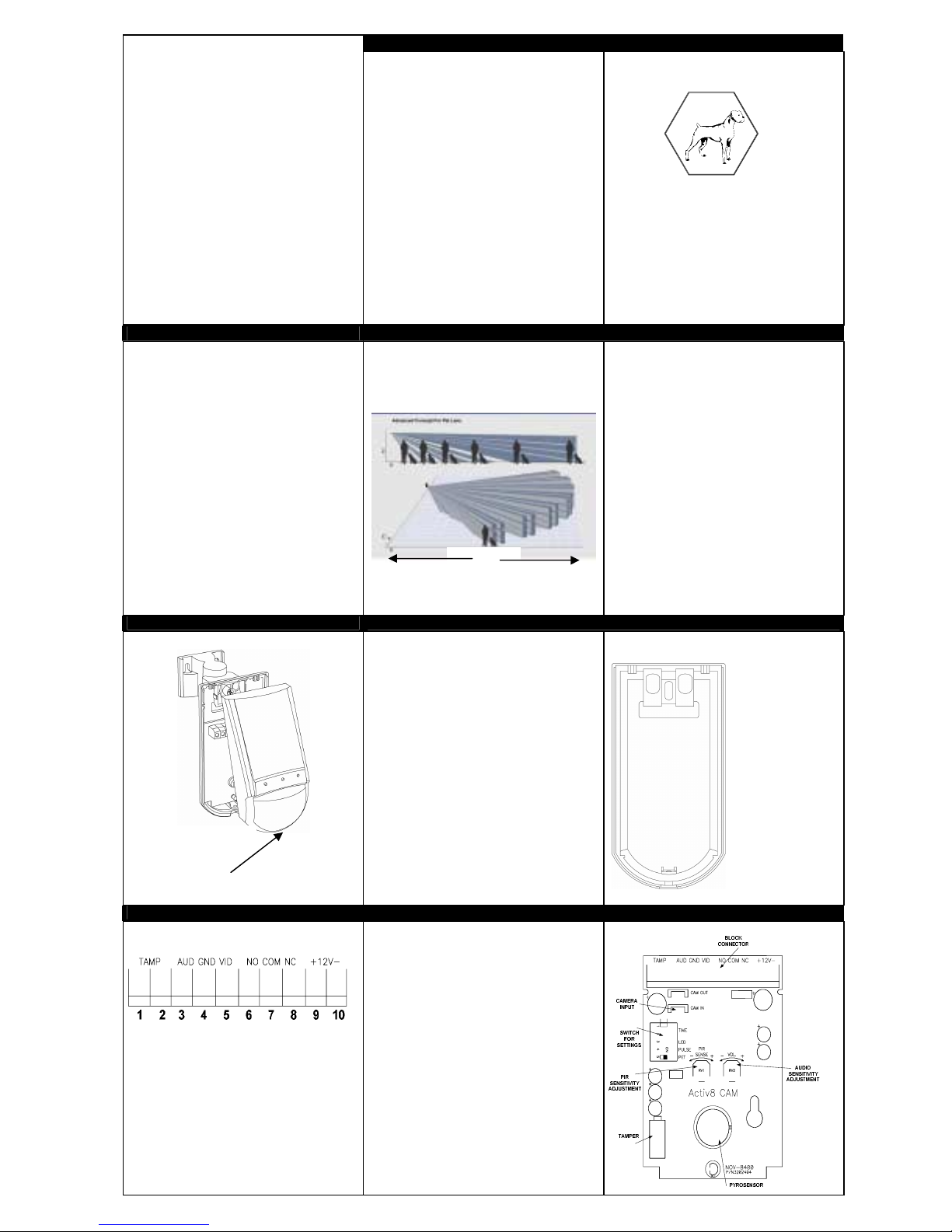
DETECTION PATTE R N
PIR sensing device and general
• Quad (four element) PYRO sensor and hard
lens for outstanding detection performance
and elimination of false alarms.
• VLSI based electronics with
movement speed spectrum
analysis.
• User-friendly installation with
swivel bracket.
• BI directional temperature
compensation.
• Environmental immunity.
• The ACTIV8 MONO/COLOUR
provides pet immunity up to 25Kg.
Pet active bellow 1m.
• Height installation calibrations free from 1.8m
to 2.4m.
• Wide range operating voltage.
•
High reliability and trouble free operation
REMOVAL OF FRONT COVER MOUNTING DETECTOR BASE
Unscrew the holding
screw and open base
15m
.
SELECT MOUNTING LO CATION
1. To remove the front cover, unscrew the holding
screw and gently raise the front cover.
2. To remove the PC board, carefully unscrew the
holding screw located on the PC board.
3. Break out the desired holes for proper installing.
4. Put wire through the bracket and holes ”A”.
5. Mount the detector base to the wall or on the
ceiling with a suitable bracket. (Install bracket).
6. Reinstall the PC board by fully tightening the
holding screw. Connect wire to terminal block.
7. Replace the cover by inserting it back in the
appropriate closing pins and screw in the holding
screw.
TERMINAL BLOCK CONNECTIONS
Terminals 1 & 2 - Marked “ TAMP ”
If a Tamper function is required connect these
terminals to a 24-hour normally closed protective
zone in the control unit. If the front cover of the
detector is opened, an immediate alarm signal will
be sent to the control unit.
Terminals 3 & 4 - Marked “ AUD ”& “GND”
This is the audio signal output. These two
terminals should be connected to an audio input.
Terminals 4 & 5 - Marked “ GND ”& “VID”
This is the video signal output. These two
terminals should be connected to video input.
DETECTOR INSTALL ATIO N CIRCUIT LAYOUT
Terminals 6,7 & 8 - Marked “ NO,COM &NC ”
These are the output relay contacts of the
detector. Connect to a normally closed or normally
opened zone in the control panel.
Terminal 9 - Marked “ + ” (+12V)
Connect to a positive Voltage output of 8.2 -16Vdc
source (usually from the alarm control unit)
Terminal 10 - Marked “ - ” (gnd)
Connect to the negative Voltage output or ground
of the control panel.
The Activ8 MONO/COLOUR provides
immunity up to 25Kg. For better immunity
avoid installation in areas where pets can
reach upwards.
Choose a location most likely to intercept an
intruder. (Our recommendation is a corner
installation). See detection pattern. The quadelement high quality sensor detects motion
crossing the beam; it is slightly less sensitive
detecting motion toward the detector.
The ACTIV8 MONO/COLOUR performs best
when provided with a constant and stable
environment.
AVOID THE FOLLOWING LOCATIONS
• Facing direct sunlight.
• Facing areas that may change temperature
rapidly.
• Areas where there are air ducts or
substantial airflows.
The ACTIV8 MONO/COLOUR performs better
when provided with a constant and stable
environment.
KNOCKOUT HOLES
A
TYPICAL INSTALLATIO N
A
A. Wire access
holes
B
B. For bracket
mounting
Page 2
SETTING UP THE DE TE CTOR
TIME ADJUSTMENT
SWITCH 1 & 2 OF DIP-5 SWITCH FOR
SETTINGS “TIME”
options).
Position Left – “OFF”.
Position Right – “ON”.
1 2 TIME RELAY CLOSE/OPEN
ON ON 2 SEC
ON OFF 15 SEC
OFF ON 60 SEC
OFF OFF 240 SEC
The N.C. Relay opens for 1.8 – 2 sec. when an
alarm occurs.
-
provides N.O. relay. (Four
SETTING UP THE DE TECTOR TEST PROCEDURE BRACKET INSTALLATION OPTIONS
SWITCH 3 OF DIP-5 SWITCH FOR SETTINGS
“LED” - LED Enable / Disable
Position On - LED ENABLE
The RED LED will activate when the detector
is in alarm condition.
Position Off - LED DISABLE
The LED is disabled.
Note: the state of the switch “LED” does not
affect the operation of the relay.
When an intrusion is detected, the LED will
activate and the alarm relay will switch into alarm
condition for 2 sec.
AUDIO SENSITIVITY ADJUSTMENT
Use the potentiometer “VOL.” (RV2) to adjust the
audio sensitivity.
Rotate the potentiometer clockwise to increase
sensitivity.
Rotate the potentiometer counter-clockwise to
decrease sensitivity.
WALL INSTALLATION
PIR SENSITIVITY ADJUSTMENT
SWITCH 4 OF DIP-5 SWITCH FOR SETTINGS
“PULSE” - provides sensitivity control of the PIR
according to the environment.
Position Left – “OFF” – Low sensitivity
For harsh environments.
Position Right – “ON” – High sensitivity
For stable environments.
POTENTIOMETER “RV1” – adjustment
according to protected area range.
Use RV1 to adjust the detection range between
68% and 100% (factory set to 84%). Rotate the
potentiometer clockwise to increase range,
counter-clockwise to decrease range.
Wait for one minute warm up
12 Vdc power. Conduct testing with the protected
area cleared of all people.
time after applying
Walk test
1. Remove front cover.
Set LED to ON position.
2. Reassemble the front cover.
3. Start walking slowly across the detection zone.
4. Observe that the red LED lights whenever
motion is detected.
5. Allow 5 sec. between each test for the detector
to stabilize.
6. After the walk test is completed, you can set the
LED to OFF position.
NOTE:
Walk tests should be conducted, at least once a
year, to confirm proper operation and coverage of
the detector.
PET IMMUNITY SETTING
SWITCH 5 OF DIP-5 SWITCH FOR SETTINGS
“PET” 15kg – 25kg
Position Right “ON”
Immunity to an animal up to 15 kg
Position Left “OFF”
Immunity to an animal up to 25 kg
TECHNICAL SPECIFICATION
TECHNICAL SPECIFICAT IO N
Detection Method Quad (four) element PIR
Power Input 7.8 to 16 Vdc
Current Draw Mono: 115 mA
Colour: 135 mA
Temperature
Compensation YES
Alarm Period 2 +/- 1 sec
Alarm Output N.C 28Vdc 0.1 A with 10 Ohm series protection resistors
Tamper Switch N.C 28Vdc 0.1A with 10 Ohm series protection resistor - open
when cover is removed
Warm Up Period 1 min
LED Indicator
Red LED is ON during alarm
Dimensions 121mm x 60mm x 37mm
Weight (inc. battery) 135 gr.
Camera
Camera Type B&W: CCIR or EIA
COLOR: PA L or N TSC
Picture Elements 290K ( CCIR;PAL) or 250K ( EIA; NTSC)
Resolution 400lines(CCIR;EIA) or 330lines
(PAL;NTSC)
Sensitivity 0.1Lux - F2.0 ( CCIR;EIA) or
2.0Lux - F1.2 (PAL;NTSC)
S/N Ratio Better then 48 dB
Shutter Control Electronic Auto-Iris
Lens Mount F 3.6mm standard (optional available)
Video Output 1V p-p 75Ω
Audio
Response Omnidirectional
AGC 20dB
Sensing Element Electret Microphone
Output Impedance 32Ω
For Technical Support, please
call 01268 563 247.
35494AE50
 Loading...