


NetAXS™
Access Control Unit
User’s Guide
If this panel is to be added to an
existing loop, then all panels
need to be upgraded. Please
see www.honeywellaccess.com.
April 2009 © 2009 Honeywell. All rights reserved. 800-04410, Revision A

Copyright© 2009 Honeywell. All rights reserved.
All product and brand names are the service marks, trademarks, registered trademarks,
or registered service marks of their respective owners. Printed in the United States of
America. Honeywell reserves the right to change any information in this document at
any time without prior notice.
Microsoft and Windows are registered trademarks of Microsoft Corporation.
Windows Server is a trademark of Microsoft Corporation.
Ordering Information
Please contact your local Honeywell representative or visit us on the web at
www.honeywellaccess.com for information about ordering.
Feedback
Honeywell appreciates your comments about this manual. Please visit us on the web at
www.honeywellaccess.com to post your comments.

CONTENTS
What’s New in Release 3.1.8
Dynamic Screens and Performance Enhancements ..................................................................... ix
Multi-language Support
CSV Reports and Card Upgrade
Reverse IP
............................................................................................................................................ x
Chapter 1 Connecting to the Web Server
1.1 Overview ........................................................................................................................................ 1
1.2 Connecting to the Web Server
1.3 Reading the Select Panel
Chapter 2 Configuring via the Web Server
2.1 Overview ...................................................................................................................................... 10
2.2 Configuring the System
2.2.1 Host/Loop Communications Tab .......................................................................... 11
2.2.2 General Tab ........................................................................................................... 14
2.2.3 File Management Tab............................................................................................ 17
2.2.4 Network Tab.......................................................................................................... 20
2.2.5 Site Codes Tab....................................................................................................... 21
2.2.6 Downstream Devices Tab...................................................................................... 23
2.3 Configuring Time Management
2.3.1 Current Time Tab .................................................................................................. 24
2.3.2 Time Zones Tab..................................................................................................... 26
2.3.3 Holidays Tab ......................................................................................................... 29
2.4 Configuring the Doors
2.4.1 Reader Tab............................................................................................................. 31
2.4.2 Outputs Tab ........................................................................................................... 38
2.4.3 Inputs Tab.............................................................................................................. 42
2.5 Configuring Access Levels
2.6 Maintaining Cards
2.6.1 Adding New Cards ................................................................................................ 47
2.6.2 Displaying and Modifying Cards .......................................................................... 49
2.6.3 Deleting Cards ....................................................................................................... 50
2.6.4 Displaying Reports ................................................................................................ 51
.................................................................................................................... ix
...................................................................................................... x
.................................................................................................... 2
.............................................................................................................. 7
............................................................................................................. 11
............................................................................................... 24
................................................................................................................ 31
........................................................................................................ 45
....................................................................................................................... 47
NetAXS™ Access Control Unit User’s Guide, Document 800-04410, Revision A iii

2.7 Configuring Other I/O & Groups Tab ..................................................................................... 52
2.7.1 Inputs Tab.............................................................................................................. 52
2.7.2 Outputs Tab ........................................................................................................... 55
2.7.3 Groups Tab ............................................................................................................ 57
2.8 Configuring Interlocks
2.9 Configuring Users
............................................................................................................... 59
....................................................................................................................... 61
Chapter 3 Configuring via WIN-PAK
3.1 Overview ...................................................................................................................................... 65
3.2 Adding a New NetAXS™ Panel
3.2.1 Creating the Panel with Quick Start Wizard ......................................................... 66
3.2.2 Configuring the Panel Manually ........................................................................... 67
.............................................................................................. 66
Chapter 4 Monitoring NetAXS™ Status
4.1 Overview ...................................................................................................................................... 75
4.2 Monitoring Alarms
4.3 Monitoring Events
4.4 Monitoring Inputs
4.5 Monitoring Outputs
4.6 Monitoring System Status
..................................................................................................................... 76
...................................................................................................................... 79
....................................................................................................................... 82
.................................................................................................................... 85
......................................................................................................... 87
Chapter 5 Upgrading NetAXS™ Firmware
A.1 Overview ..................................................................................................................................... 89
A.2 NetAXS™ Release 3.1.8 Upgrade Procedure
A.2.1 Planning the Upgrade ........................................................................................... 89
A.2.2 Mixed Revision Loops.......................................................................................... 89
A.2.3 Uploading Data from the Panel ............................................................................ 90
A.2.4 Upgrades to Gateway vs. Multi-drop Panels ........................................................ 90
A.2.5 Upgrade Notes ...................................................................................................... 92
A.2.6 Clearing the Cache in the Internet Browsers Used by the
NetAXS™ Web Server .......................................................................................... 93
....................................................................... 89
Index
iv www.honeywell.com

LIST OF FIGURES
Figure 1-1: NetAXS™ Web Server Hub Connection ................................................................ 2
Figure 1-2: NetAXS™ Web Server Direct Connection ............................................................. 3
Figure 2-1: NetAXS™ System Configuration Flow Chart ...................................................... 10
Figure 2-2: Configuration > System >Host/Loop Communications Tab ................................. 11
Figure 2-3: Configuration > System > General Tab ................................................................. 14
Figure 2-4: Configuration > System > File Management Tab ................................................. 17
Figure 2-5: Configuration > System > Network Tab ............................................................... 20
Figure 2-6: Configuration > System > Site Codes Tab ............................................................ 21
Figure 2-7: Configuration > System > Downstream Devices Tab ........................................... 23
Figure 2-8: Configuration > Time Management > Current Time Tab ..................................... 24
Figure 2-9: Configuration > Time Management > Time Zones Tab ....................................... 26
Figure 2-10: Configuration > Time Management > Holidays Tab .......................................... 29
Figure 2-11: Configuration > Doors > Reader > General Tab ................................................. 31
Figure 2-12: Configuration > Doors > Reader > Card Formats Tab ........................................ 35
Figure 2-13: Discrete Lock Output Configuration ................................................................... 38
Figure 2-14: Configuration > Doors > Outputs > Group Tab >Lock ....................................... 39
Figure 2-15: Configuration > Doors > Inputs Tab ................................................................... 42
Figure 2-16: Configuration > Access Levels ........................................................................... 45
Figure 2-17: Cards > Add Cards .............................................................................................. 47
Figure 2-18: Cards > Card Data ............................................................................................... 49
Figure 2-19: Cards > Delete Cards ........................................................................................... 50
Figure 2-20: Configuration > Other I/O & Groups > Inputs Tab ............................................. 53
Figure 2-21: Configuration > Other I/O & Groups > Outputs Tab .......................................... 55
Figure 2-22: Configuration > Other I/O & Groups > Groups Tab ........................................... 57
Figure 2-23: Configuration > Interlocks .................................................................................. 59
Figure 2-24: Configuration > Users ......................................................................................... 62
Figure 3-1: Quick Start Wizard - Panel Screen ........................................................................ 66
Figure 3-2: WIN-PAK Panel Configuration Screen - Basic Tab ............................................. 67
Figure 3-3: WIN-PAK Panel Configuration Screen - Card Format Tab .................................. 68
Figure 3-4: WIN-PAK Panel Configuration Screen - Time Zones Tab ................................... 69
Figure 3-5: WIN-PAK Panel Configuration Screen - Options Tab ......................................... 70
Figure 4-1: Status > Alarms > Unacknowledged Tab .............................................................. 76
Figure 4-2: Status > Alarms > Acknowledged Tab .................................................................. 77
Figure 4-3: Status > Events > Panel Tab .................................................................................. 79
Figure 4-4: Status > Events > Web Tab ................................................................................... 81
Figure 4-5: Status > Inputs ....................................................................................................... 82
NetAXS™ Access Control Unit User’s Guide, Document 800-04410, Revision A v

Figure 4-6: Status > Outputs > Doors/Aux/Other/DnStr Tab .................................................. 85
Figure 4-7: Status > Outputs > Groups Tab ............................................................................. 86
Figure 4-8: Status > System ..................................................................................................... 87
vi www.honeywell.com

LIST OF TABLES
Table 1-1: Reading the Select Panel ............................................................................................7
Table 2-1: Configuration > System > Host/Loop Communications Tab Field Descriptions.....12
Table 2-2: Configuration > System > General Tab Fields ........................................................14
Table 2-3: Configuration > Time Management Tab Field Descriptions ................................... 25
Table 2-4: Configuration > Doors > Reader Tab Descriptions .................................................33
Table 2-5: Configuration > Doors > Reader > Card Format Fields ..........................................35
Table 2-6: Configuration > Doors > Output Tab Field Descriptions ........................................41
Table 2-7: Configuration > Doors > Inputs Tab Field Descriptions .........................................44
Table 2-8: Cards > Add Cards Field Descriptions ....................................................................48
Table 2-9: Cards > Reports Field Descriptions .........................................................................51
Table 2-10: Configuration > Other I/O & Groups > Inputs Tab Field Descriptions ................. 54
Table 2-11: Configuration > Other I/O & Groups > Outputs Tab > Fields ..............................56
Table 2-12: Configuration > Other I/O & Groups > Groups Tab Field Descriptions ...............58
Table 2-13: Configuration > Interlocks > Field Descriptions ...................................................60
Table 3-1: Interlock Reassignments for NetAXS™ ..................................................................72
Table 4-1: Status > Alarms Field Descriptions .........................................................................77
Table 4-2: Status > Events > Panel Tab Field Descriptions ......................................................80
NetAXS™ Access Control Unit User’s Guide, Document 800-04410, Revision A vii

viii www.honeywell.com

What’s New in Release 3.1.8
Dynamic Screens and Performance Enhancements
Dynamic screens are screens that can refresh data without re-submitting. In the
Honeywell NetAXS™ panel, there is now a persistent connection between the web
screens and the panel. This allows status updates from the panel to be pushed out to
the screens automatically to display the data seamlessly on the screen.
In addition to the dynamic screens, other panel-side enhancements have been made
that improve screen performance. Now the web server detects when panels of a loop
come online faster. In the past, there was a 30- to 45-second delay during which a
panel could be online before the web would detect it. Data transfer between the panel
and web browsers has been optimized to reduce bandwidth requirements and improve
screen response times overall.
Multi-language Support
Multi-language support consists of “language files” installed with the firmware or
imported to a panel. A language selection is available on a per-user basis. The
language files are available by upload from the panel or from the Honeywell website.
You can customize the upload.
There are options to import, export, or delete the language files from a panel. During
upgrades, the language files with default names are replaced by those included with
the firmware, so we recommend that customizations be saved and imported with a
different filename than any present after upgrade. After toggling firmware sets, some
phrases may change or appear in English until the language file(s) matching the active
firmware version are imported, or the next upgrade is completed.
NetAXS™ Access Control Unit User’s Guide, Document 800-04410, Revision A ix

CSV Reports and Card Upgrade
CSV Reports and Card Upgrade
A requested feature was added to the NetAXS™ panel to support card holder updates and additions to
the database via a CSV (comma separated variable) file. In order to support this, a CSV report is first
created via a request from the web page. This report can be edited directly or loaded into a spreadsheet
to be edited. If loaded into a spreadsheet, the file can be saved in CSV format. The modified CSV file
can then be downloaded to the gateway and loop panels.
Also, an option is provided to either replace or append the card database. Replacing the database
deletes the existing card database, and appending the existing database adds new cards and updates to
existing cards, if needed. This file is downloaded first to the gateway panel, and then automatically to
each downstream panel. The file is sent to the downstream panel as a background process that allows
other web screens to continue to operate. Note that the panels will not need to reboot after the file is
downloaded.
Reverse IP
Reverse IP is implemented in the NetAXS™ panel to function with the WIN-PAK CS Reverse IP
communication setting. This allows the panel to exist behind a firewall while communication to
WIN-PAK CS is conducted on a pre-set port. This allows the NetAXS™ panel to be on a DHCP
network. Reverse IP connections are currently limited to one NetAXS™ panel per WIN-PAK CS port.
The NetAXS™ panel does not currently support encrypted reverse IP communication.
x www.honeywell.com

Connecting to the Web Server
In this chapter...
Overview 1
Connecting to the Web Server 2
1.1 Overview
A NetAXS™ access control site is configured with a host system and NetAXS™
access control units that exceed existing N-1000-III/IV, Pro Series specifications and
approvals, and that communicate with each other and with a variety of input and
output devices. Each access control unit, or panel, has four reader ports. See the
NetAXS™ NX4L1 Installation Guide, NetAXS™ NX4S1 Installation Guide, or
NetAXS™ NX4S2 Installation Guide to view illustrations of the supported NetAXS™
system configurations.
1
You can communicate with the NetAXS™ access control unit either through a host
software system or by connecting to the NetAXS™ web server by an Ethernet
connection. This chapter describes how to connect to the NetAXS™ web server.
Chapter 2 describes how to use the NetAXS™ web interface after you are connected
to the NetAXS™ panel through the NetAXS™ web server. Chapter 3 describes how
to use the web server interface.
NetAXS™ Access Control Unit User’s Guide, Document 800-04410, Revision A 1
Connecting to the Web Server
Connecting to the Web Server
1.2 Connecting to the Web Server
This section describes how to connect a computer to the NetAXS™ web server via Ethernet and
Internet Explorer.
Notes:
• The NetAXS™ panel that you are connecting to the computer is the Gateway panel. DIP switch
6 on a Gateway panel must be set to ON for a successful connection.
• The Microsoft Windows™ screen captures used in this section reflect the Windows 2000™
platform. If you are using another Windows™ platform, the screens will be somewhat
different.
Perform the following steps:
1. Connect your computer's Ethernet port and the NetAXS™ panel's Ethernet Port by using either
of two methods:
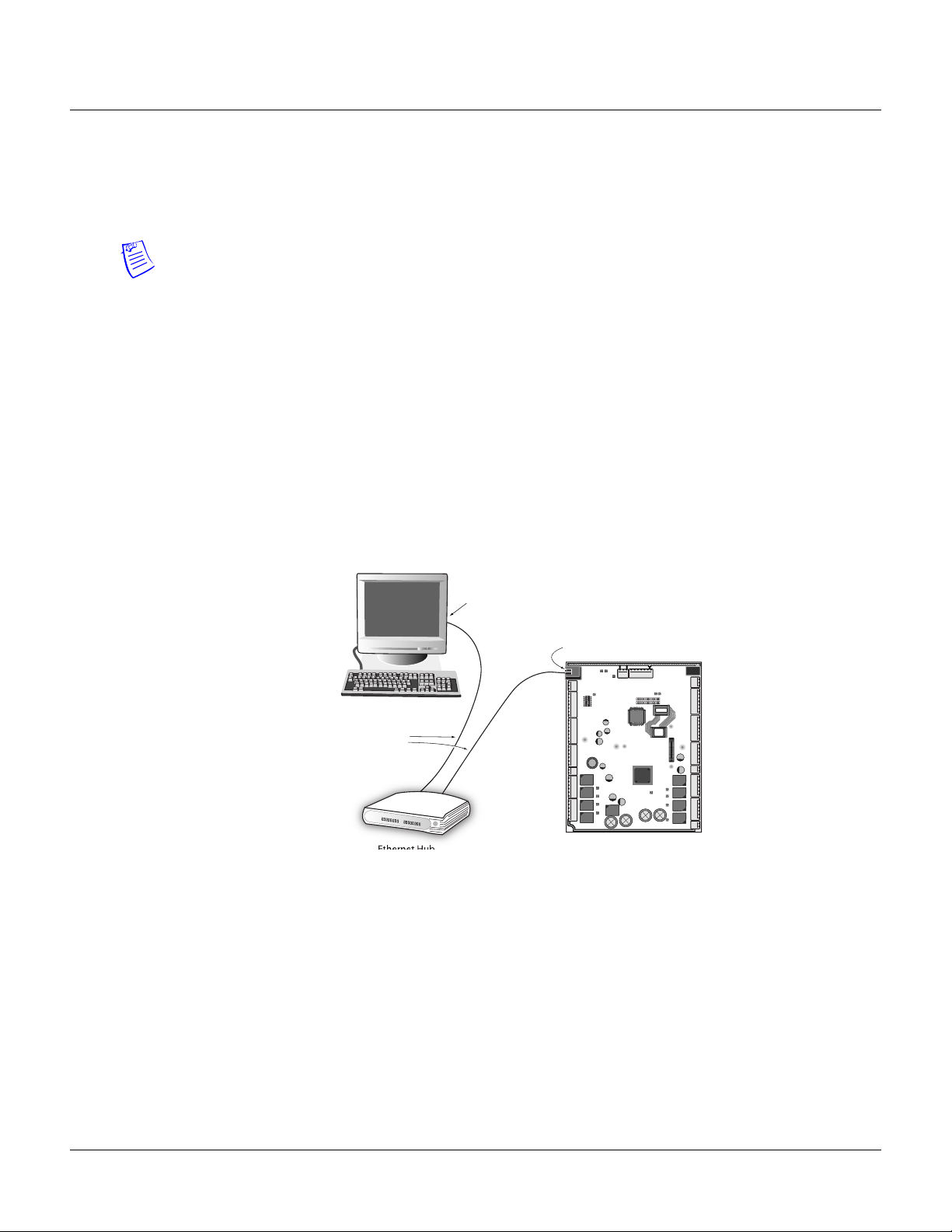
a. Connect both the computer’s Ethernet port and the NetAXS™ panels Ethernet port to an
Ethernet hub with standard Ethernet patch cables.
Figure 1-1: NetAXS™ Web Server Hub Connection
Terminal
Ethernet Port
Ethernet Port
Ethernet
Cable
Ethernet Hub NetAXS Panel
b. Connect the computer’s Ethernet port directly to the NetAXS™ panel’s Ethernet port
with an Ethernet cable.
2 www.honeywell.com
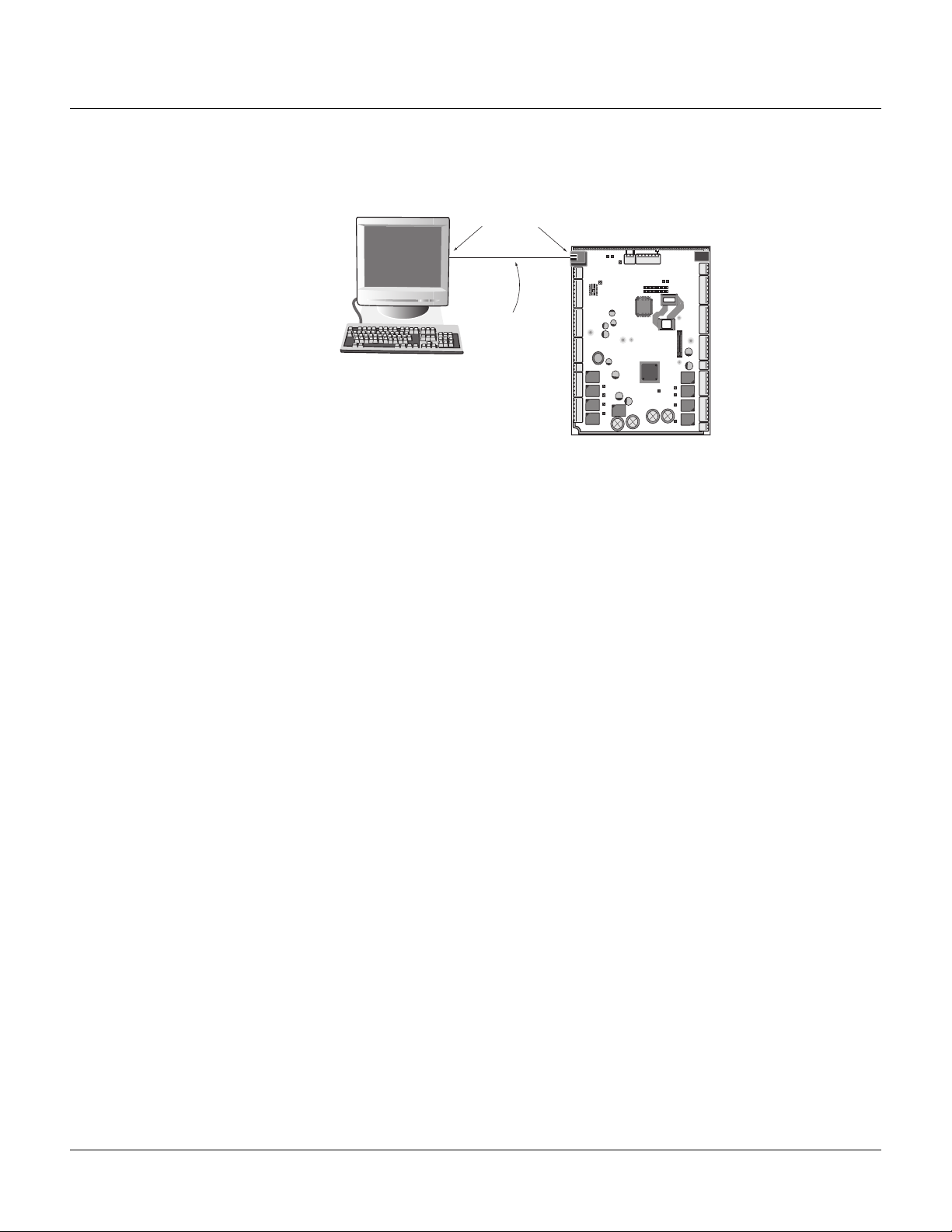
Figure 1-2: NetAXS™ Web Server Direct Connection
Connecting to the Web Server
Connecting to the Web Server
Terminal
Ethernet Port
Ethernet
Cable
2. Configure the computer’s network connection:
a. Select
Start > Settings > Control Panel.
b. Click Network and Dial-up Connections.
NetAXS Panel
NetAXS™ Access Control Unit User’s Guide, Document 800-04410, Revision A 3
Connecting to the Web Server
Connecting to the Web Server
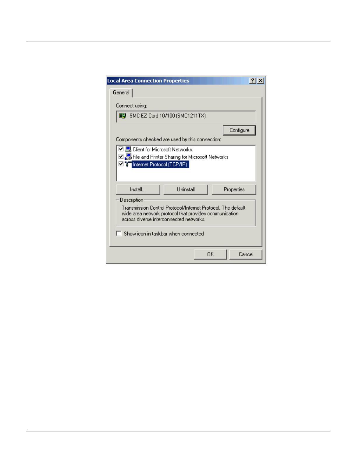
c. Identify your local Ethernet connection (commonly labeled Local Area Connection), and
right click the icon to display the Local Area Connection Properties screen.
4 www.honeywell.com
d. Highlight the Internet Protocol (TCP/IP) connection.
e. Click
f.
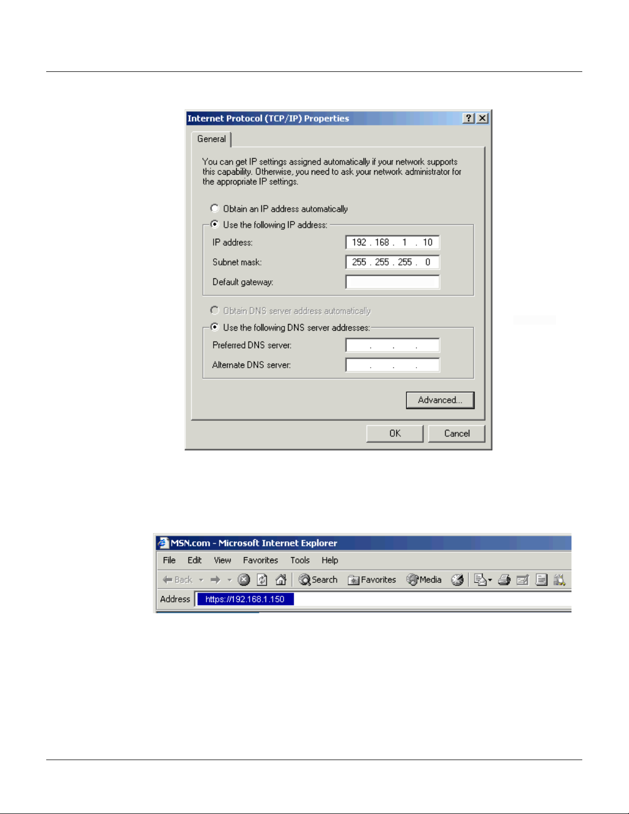
Properties to display your system’s current Internet Protocol properties.
Important: Keep a record of your computer’s current network configuration as it appears
in this screen. You will need to re-instate this configuration later.
g. Select “Use the following IP address."
h. Enter "192.168.1.10" in the IP address field.
i. Enter "255.255.255.0" in the Subnet mask field.
Connecting to the Web Server
Connecting to the Web Server
j. Click OK to accept the entries.
3. Open your browser (Internet Explorer shown below), and enter https://192.168.1.150 as the
target address.
NetAXS™ Access Control Unit User’s Guide, Document 800-04410, Revision A 5
Connecting to the Web Server
Connecting to the Web Server
4. Press the Enter key to display the Honeywell NetAXS™ login screen.
Note: If you are using Microsoft Internet Explorer 7, and you receive a certificate error
message, follow these steps to clear it:
a. Enter the IP Address of the panel into the URL box.
b. Click Continue to the website (not recommended) to display the login screen.
c. Click Certificate Error at the top-right of the IP Address. The “Untrusted Certificate”
screen appears.
d. Click the View Certificates bar. The “Certificate Information” screen appears.
e. Click Install Certificate. The “Certificate Import Wizard” screen appears.
f. Click Next and follow the prompts; leave all settings at their default values. A Security
Warning asks if you want to install the certificate.
g. Click Ye s. A Certificate Import Wizard message states “The import was successful.”
h. Click OK. The Certification Information message appears again.
i. Click OK.
j. Close the web browser and re-open it.
k. Enter the IP Address again into the URL box. The login screen appears without the
certificate error
5. Enter “admin” in the User Name field, and enter “admin” in the Password field. Both the user
name and password are case-sensitive.
6. Click
Login to display the NetAXS™ main window. Note that the Select Panel column on the
right edge of the screen displays all panels available to the computer. This list will include the
gateway panel that you are connected to over Ethernet and any downstream panels connected
via RS-485 to the Gateway panel.
Note: It is recommended that you change your default user name (admin) and password
(admin) to a new user name and password at this time. To do this, proceed to the instructions in
Chapter 2, Configuring the NetAXS™ System, Steps to modify a user:, page 63.
6 www.honeywell.com
1.3 Reading the Select Panel
The Select Panel is located at the right margin of the NetAXS™ web server main screen, shown in the
preceding section. The presence of a number in one of the Select Panel cells indicates that its
associated panel is online. For example, if you see a number 1 in a cell, this indicates that panel 1 is
online. The combinations of size and color of the number and the color of the cell background indicate
the panel’s status, as shown in the following table:
Notes:
• Holding the cursor over a cell also displays a popup message, which conveys the panel in that
cell is online or selected.
• The Select Panel refreshes automatically when the panel’s status changes.
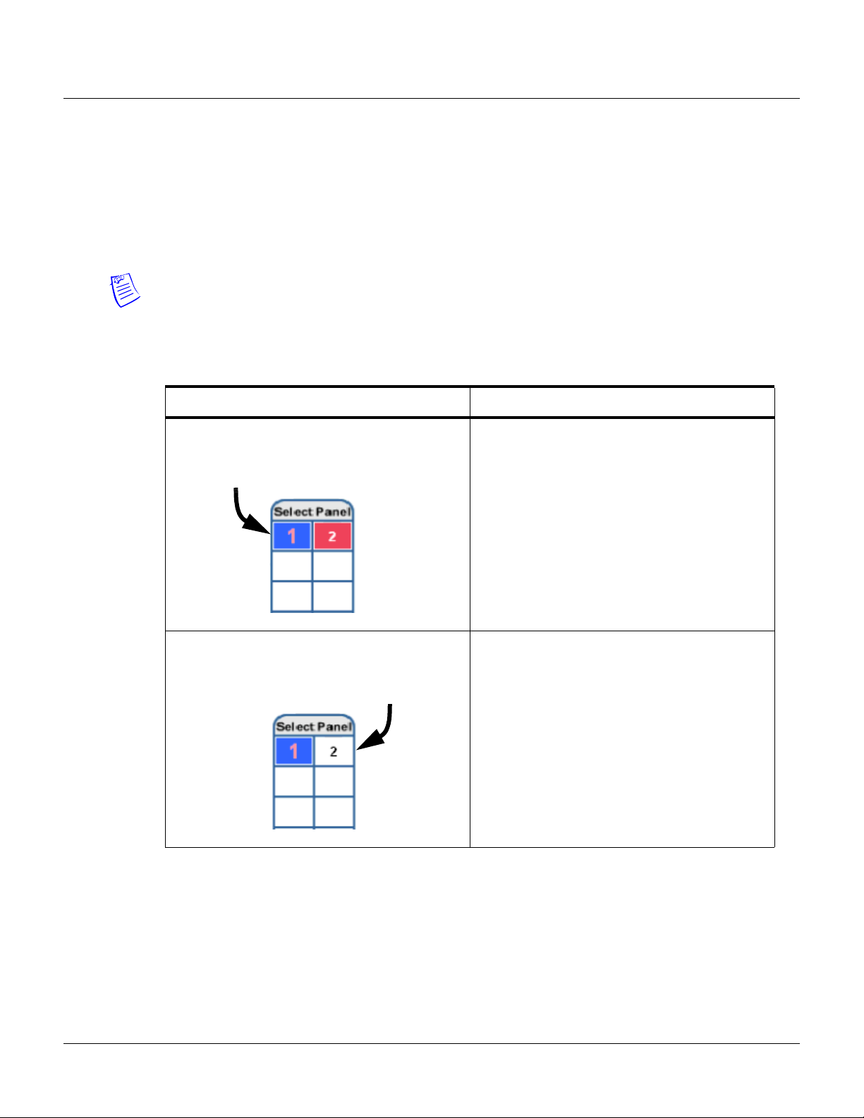
Table 1-1: Reading the Select Panel
Cell Display Status
Connecting to the Web Server
Reading the Select Panel
Large red number on a blue background, such as
“1” in the example below:
Small black number on white background, such as
“2” in the example below:
Panel 1 is selected, and it has unacknowledged
alarms.
Panel 2 is not selected and it has no
unacknowledged alarms.
NetAXS™ Access Control Unit User’s Guide, Document 800-04410, Revision A 7
Connecting to the Web Server
Reading the Select Panel
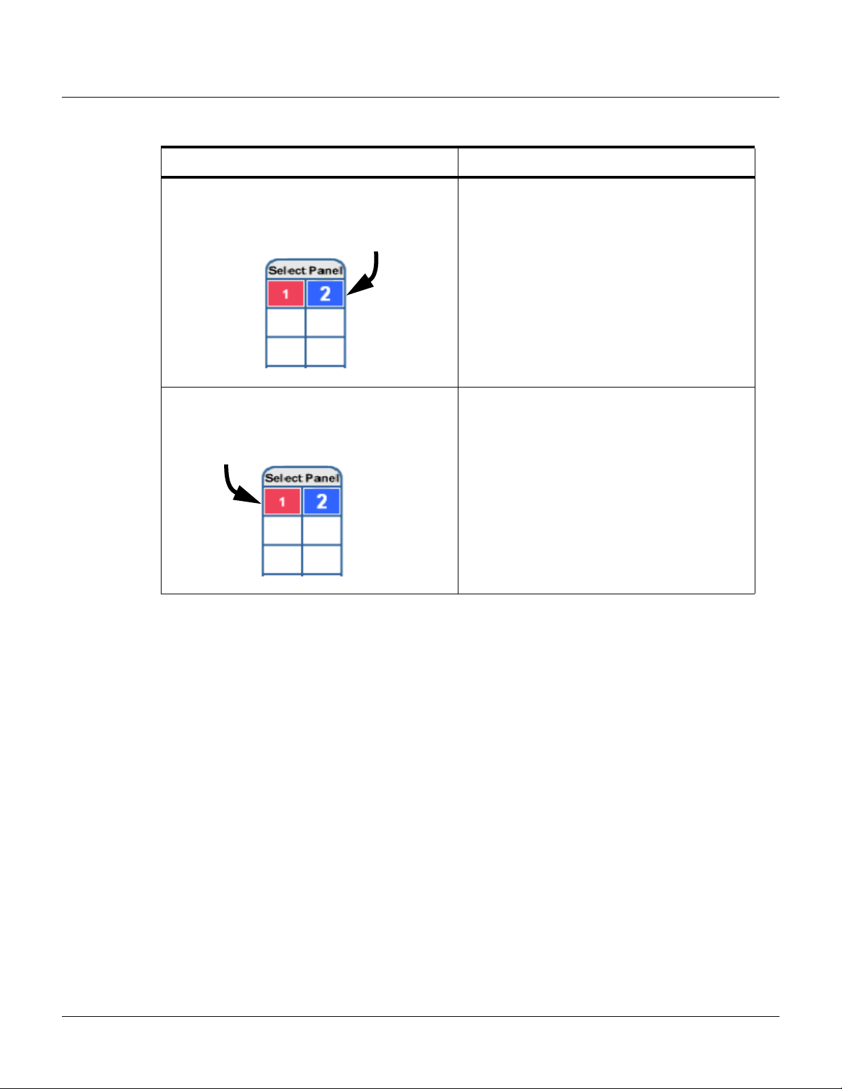
Table 1-1: Reading the Select Panel (continued)
Cell Display Status
Large white number on blue background, such as
“2” in the example below:
Small white number on a red background, such as
“1” in the example below:
Panel 2 is selected, and it has no unacknowledged
alarms.
Panel 1 is not selected, but it does have
unacknowledged alarms.
8 www.honeywell.com

Configuring via the Web Server
In this chapter...
Overview 10
Configuring the System 11
Configuring the Doors 31
Configuring Other I/O & Groups Tab 52
Configuring Interlocks 59
Configuring Time Management 24
Configuring Access Levels 45
Configuring Users 61
2
NetAXS™ Access Control Unit User’s Guide, Document 800-04410, Revision A 9

Configuring via the Web Server
Configuring the System
2.1 Overview
This chapter explains the NetAXS™ configuration functions as accessed via the NetAXS™ web
server. These functions should be performed only by the NetAXS™ system administrator or service
personnel.
Caution: The sequence of NetAXS™ configuration tasks is critical. If the sequence given below is not
followed, the NetAXS™ system cannot be successfully configured.
The flow chart in Figure 2-1 shows the order in which to perform the administrative functions.
Figure 2-1: NetAXS™ System Configuration Flow Chart
Configure the Panel
Configuration > System > Host/Loop Communications (Host/Loop
Communications Tab, page 11)
Configuration > System > Network (Network Tab, page 20)
Configuration > System > General (General Tab, page 14)
Configuration > System > Site Codes (Site Codes Tab, page 21)
Configure the Time Zones
Configuration > Time Management > Time Zones (Time Zones Tab, page 26)
Configure the Doors
Configuration > Doors > Reader (Reader Tab, page 31)
Configuration > Doors > Output (Outputs Tab, page 38)
Configuration > Doors > Inputs (Inputs Tab, page 42)
Configure the Access Levels
Configuration > Access Levels (Configuring Access Levels, page 45)
Create the Cards
Cards > Add Cards (Adding New Cards, page 47)
10 www.honeywell.com
Assign Access Levels to Cards
Cards > Add Cards (Adding New Cards, page 47)
2.2 Configuring the System
2.2.1 Host/Loop Communications Tab
In order to maintain your NetAXS™ system configuration or to monitor its status, you must connect to
the NetAXS™ panel by using one of two modes:
• Host mode (monitor only) – a host software system, such as WIN-PAK™, connects to the panel
(through the NetAXS™ gateway panel, which has an on-board PCI communications adapter),
and it enables you to monitor the status of the NetAXS™ system. The on-board PCI adapter
functions as an interface between a host computer’s RS-232 port and one or more panels
connected on the Multidrop line.
• Web mode (configure and monitor) – the NetAXS™ web server connects to the panel and
enables you to configure the panel and monitor system status.
This tab enables you to select and configure the communication mode you will use to connect to the
panel.
Note: A Gateway panel installed with release 3.1.8 or newer of NetAXS™ firmware cannot
communicate fully with previous versions of NetAXS™ that may be installed on existing panels. If
your panels are running release 2 (v2.2.21 or older), they must be upgraded to release 3.
Configuring via the Web Server
Configuring the System
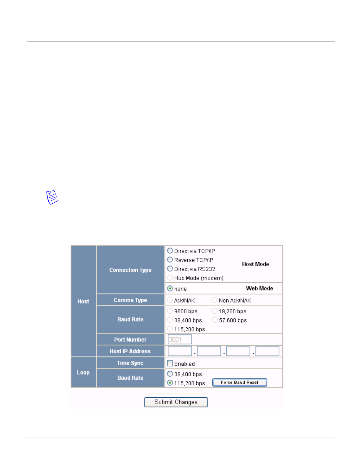
Click the
Host/Loop Communications tab:
Figure 2-2: Configuration > System >Host/Loop Communications Tab
NetAXS™ Access Control Unit User’s Guide, Document 800-04410, Revision A 11

Configuring via the Web Server
Configuring the System
The Host/Loop Communications tab enables you to:
• Configure the following host settings:
– Connection type (host or web server)
– Communications type
–Baud rate
– Port number
– Time sync
• Configure the loop baud rate for communication among downstream panels.
Steps: Use the descriptions in the following table to configure the settings:
Table 2-1: Configuration > System > Host/Loop Communications Tab Field Descriptions
Host/Loop Setting Description
Host Connection type Specifies the type of physical connection
between the host and the Gateway panel.
If you are connecting from a host software
system such as WIN-PAK, select one of the
following three connection options:
Direct via TCP/IP – Host connects directly to
the panel using the TCP/IP protocol.
Reverse TCP/IP – Panel connects directly to
the host system using the TCP/IP protocol.
You must enter the host IP address in the Host
IP Address field. The communication is not
encrypted.
Direct via RS-232 – Host connects directly to
the panel via the RS-232 protocol.
Hub Mode (modem) – Host and the panel
both connect to a modem.
If you will be connecting to the panel through
the NetAXS™ web server, click None.
(Currently not supported)
12 www.honeywell.com
Comms Type Specifies the type of communications.
Ack/NAK – Provides a response (either an
acknowledgement or a
non-acknowledgement) in a transmission
between the host and panel(s). This is the
recommended communications type.
Non Ack/NAK – Does not provide a response
(either an acknowledgement or a
non-acknowledgement) in a transmission
between the host and panel(s).

Configuring via the Web Server
Configuring the System
Table 2-1: Configuration > System > Host/Loop Communications Tab Field Descriptions (continued)
Host/Loop Setting Description
Baud Rate Specifies the transmission rate (bits per
second) between the host and the panel. Select
the highest rate that your modem will support
(19,200 bps is recommended).
Port Number Specifies the port number for the Ethernet port
(default is 3001).
Host IP Address Enter the host system (or WIN-PAK server) IP
address here if you selected
in the Connection Type field on this screen.
Time Sync Synchronizes the panel’s time with the host’s
time.
Enabled – Causes the panel(s) to be
automatically time-synchronized with the
host.
Reverse TCP/IP
Loop Baud Rate Specifies the transmission rate (bits per
second) among the downstream NetAXS™
panels on the loop. For NetAXS™
downstream panels, it is recommended that
you select 115,200.
Force Baud Reset
Tells all downstream NetAXS™ panels to
change to the selected Downstream baud rate.
This saves the user from having to go to each
panel one by one
NetAXS™ Access Control Unit User’s Guide, Document 800-04410, Revision A 13
Configuring via the Web Server
Configuring the System
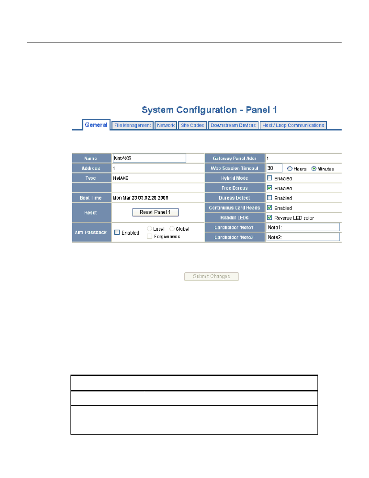
2.2.2 General Tab
Click Configuration > System in the NetAXS™ menu to display the System Configuration (General)
screen:
Figure 2-3: Configuration > System > General Tab
The General Tab enables you to:
• Set the general configuration settings.
• Reset the panel.
Steps: Use the descriptions in the following table to configure the general settings, and click Submit
Changes
Table 2-2: Configuration > System > General Tab Fields
Parameter Description
Name Unique name that identifies the panel.
Address Displays the address set by the panel’s DIP switches.
Type Displays “NetAXS” as the panel type.
14 www.honeywell.com
:

Configuring via the Web Server
Configuring the System
Table 2-2: Configuration > System > General Tab Fields
Parameter Description
Boot Time Displays the time that power was applied to the NetAXS™ panel.
Reset Reboots the panel. A reset does not change the current configuration
in the database.
Anti-Passback
Enabled – Enables anti-passback, which prevents an entrant to an
area from passing his card back to another potential entrant.
Local – Enforces anti-passback only at doors configured locally to
the panel controlling the original card read.
Global – Enforces anti-passback at panels throughout the NetAXS™
system after a successful card read at any one of the system’s readers.
Forgiveness – Causes all system codes to be reset at midnight every
day. This enables a cardholder who exited the building in the evening
without using his card to use his card for entry the following
morning.
Gateway Panel Addr Sets the panel address of the Gateway panel, or the panel directly
connected to the host system.
Web Session Timeout Activates a web session timeout after the specified time period has
elapsed. Define the time period either in minutes or in hours. Enter
the number in the box, then select either minutes or hours.
Hybrid Mode
Enabled – Implements a superior method of communication that
provides dynamic database synchronization between the NetAXS™
database and WIN-PAK SE Release 2 or WIN-PAK PE Release 2. It
allows full web functionality while using a WIN-PAK SE Release 2
or WIN-PAK PE Release 2 as the host. When connected to
WIN-PAK SE Release 2 or WIN-PAK PE Release 2 or later,
WIN-PAK enables you to:
• approve changes made via the web interface.
• import those changes into the WIN-PAK database.
• disapprove those changes and revert the panel's
configuration to the configuration stored in the WIN-PAK
database.
Note: Consult your Honeywell Access Control representative for the
latest list of Host software packages that support this feature.
Free Egress
Enabled – Configures the panel for free egress. Reader 1 activates
output 1, reader 2 activates output 2, reader 3 activates output 3, and
reader 4 activates output 4. Inputs 1, 3, 5, and 7 are egress defaults
that activate outputs 1, 2, 3, and 4, respectively. Inputs 2, 4, 6, and 8
are status defaults for outputs 1, 2, 3, and 4, respectively.
NetAXS™ Access Control Unit User’s Guide, Document 800-04410, Revision A 15

Configuring via the Web Server
Configuring the System
Table 2-2: Configuration > System > General Tab Fields
Parameter Description
Duress Detect Enabled – Enables the user to trigger an alarm or output device in
times of duress, such as when the operator is forced to grant access
against his will to an unauthorized person. This feature is available
only when the reader is configured with a “Card and Pin” access
mode (see Reader Tab, page 31).
When this feature is enabled, you can configure an auxiliary output
with a pulse time and connect it to a device with an interlock (see
“Outputs Tab“ on page 55 for the output configuration).
During normal operation, the duress output does nothing. To energize
the output, the cardholder presents his card to a reader that is
configured for Card and PIN access (see “Reader Tab“ on page 31).
The cardholder then enters a PIN that is either one number higher or
one number lower than his correct PIN. For example, if his PIN is
2222, the cardholder would enter either 2221 or 2223. Even though
the PIN is incorrect, the door will still open normally, but the duress
output pulses and an alarm is generated. In this way, the cardholder
notifies others without detection by the unauthorized person.
Continuous Card Reads
Enabled – Enables continuous card reading while the output is being
energized. When this option is not enabled, a reader will not be able
to read a second card during the pulsing of the output caused by the
previous card read.
Reader LEDs Identifies the color of a reader LED when a grant is authorized.
Cardholder Note 1 Specifies any information field you might want to put on a card. For
example, if you enter “Department” here, a field labeled
“Department” appears on the card. The user who creates the card
would then enter the cardholder’s department name. See Adding
New Cards, page 47.
Cardholder Note 2 Specifies any information field you might want to put on a card. For
example, if you enter “Phone Number” here, a field labeled “Phone
Number” appears on the card. The user who creates the card would
then enter the cardholder’s telephone number. See Adding New
Cards, page 47.
16 www.honeywell.com
Configuring via the Web Server
Configuring the System
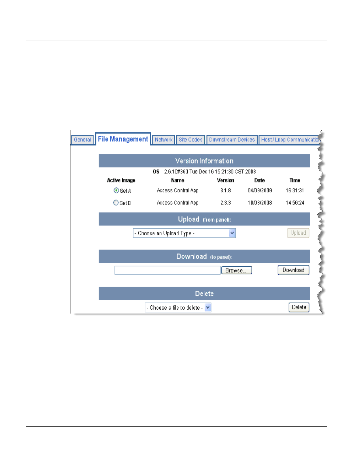
2.2.3 File Management Tab
Firmware is software that is embedded in the NetAXS™ board. The firmware provides this web
interface and all access control functionality. Periodically, the firmware is updated. This tab enables
you to download new versions of the firmware, revert to a previous version of the firmware, upload
and/or download card and configuration databases.
Click
File Management to display the File Management tab:
Figure 2-4: Configuration > System > File Management Tab
The File Management tab enables you to:
• View and re-set the current firmware configuration.
• Revert to another firmware version.
• Restore (or download) firmware.
• Back up (or upload) panel, card, and configuration data from the panel to the host system.
• Restore (or download) card database files.
• Restore (or download) backup files from the host to the panel.
• Delete a file.
NetAXS™ Access Control Unit User’s Guide, Document 800-04410, Revision A 17

Configuring via the Web Server
Configuring the System
Steps to reset the firmware version:
1. In the Active Image column, click to select the firmware version to which you want to revert.
The prompt “Switching to an alternate firmware set requires a panel reboot” appears.
2. Click
Steps to restore (or download) firmware:
OK to reboot the panel.
1. Click Browse to locate the firmware file.
2. Click
Download to download the selected firmware file.
Note: Every panel has its own database, and each panel’s database must be backed up
individually.
Steps to back up (or upload) data from the panel to the host system:
1. From the Upload dropdown list, select one of the following types of upload from the panel to
the host system:
• Card and common configuration data—uploads cards, time zones, card formats,
holidays, access levels, and site codes in a .CSV file.
• Panel configuration data—uploads inputs, outputs, groups, interlocks, readers, and panel
configuration in a .CSV file.
• Card, common, and panel configuration data—uploads both the card and panel
configuration items in a .CSV file.
• Card report (short)—uploads the Card Number, Last Name, First Name, Trace, VIP,
Limited Use, Card Expiration, Temporary, Supervisor, and Access Level card values in a
.CSV file.
2. Click
backup file on your PC. Be sure to give the backup file a useful name for easy identification
and restoring.
Note: Card report (short and long) data is stored in a 64-bit format. Microsoft Excel displays up to 32
characters. Therefore, you should save the report and then open the it in Notepad, instead of opening
the report immediately in the default .CSV format in Excel.
18 www.honeywell.com
• Card report (long)—uploads the Card Number, Last Name, First Name, Trace, VIP,
Limited Use, Card Expiration, Temporary, Supervisor, Access Levels, Site Codes,
Number of Bits, Pin, Info 1, Info 2, Time Zones, Activation Date, Issue Level, APB
State, and Control Device card values in a .CSV file.
• Alarms and events report—uploads the Date, Time, Event Type, Acknowledged Date,
Acknowledged Time, and Message of Alarms/Events for alarms and events in a .CSV
file.
• Language: English default, Spanish, French, Italian, Dutch, Czech, and simplified
Chinese. This is a text file that uploads a language package that translates the text on all
of the web screens for a user who has specified a language preference.
Upload to upload the data to the host PC or laptop. Follow the instructions to save a

Configuring via the Web Server
Configuring the System
Steps to download a card database report (.CSV file) from the host system to the panel:
1. Click Browse to locate the .CSV file.
2. Click
Download to download the file. If the file is in the correct report format, this message
appears: “Would you like to append or replace the database? Access Control does not function
while replacing a database, and updating may take several minutes.” If the file is not in the
correct report format, a message states the error condition.
If the database update is successful, this message appears: “Update Successful. Restarting Access
Control.” If the database update is not successful, a message states the error condition.
Steps to restore (or download) backup files from the host system to the panel:
1. Click Browse to locate the backup file.
2. Click
Steps to delete language files:
Download to download the selected backup file.
1. From the Delete dropdown list, select the language file you want to delete.
2. Click
Delete to delete the file.
NetAXS™ Access Control Unit User’s Guide, Document 800-04410, Revision A 19
Configuring via the Web Server
Configuring the System
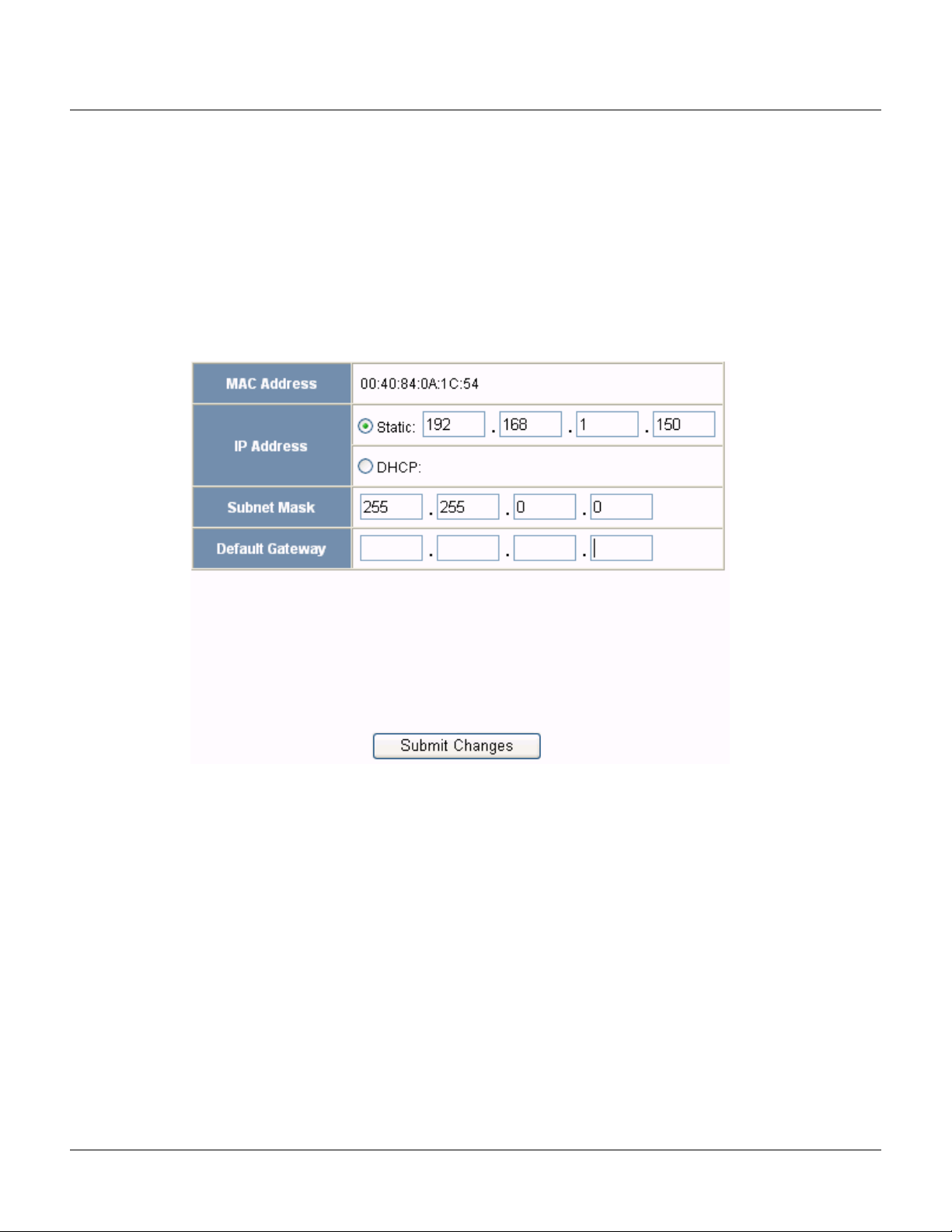
2.2.4 Network Tab
Your NetAXS™ panel is physically configured in one of a number of possible network configurations.
See the “System Configuration” section in the NetAXS™ NX4L1 Installation Guide, NetAXS™ NX4S1
Installation Guide, and NetAXS™ NX4S2 Installation Guide for illustrations of the supported network
configurations. For the panel to function in any of these configurations, the other panels and devices in
the network must know the panel’s network addresses.
Click
Network to display the Network tab:
Figure 2-5: Configuration > System > Network Tab
The Network tab enables you to:
• View the panel’s MAC address.
• View and edit the panel’s IP address.
• View and edit the panel’s subnet mask.
• View and edit the panel’s default gateway.
20 www.honeywell.com
 Loading...