

Page 1
69-2413EF-05
TrueEASE™ Humidification System
PROFESSIONAL INSTALLATION GUIDE
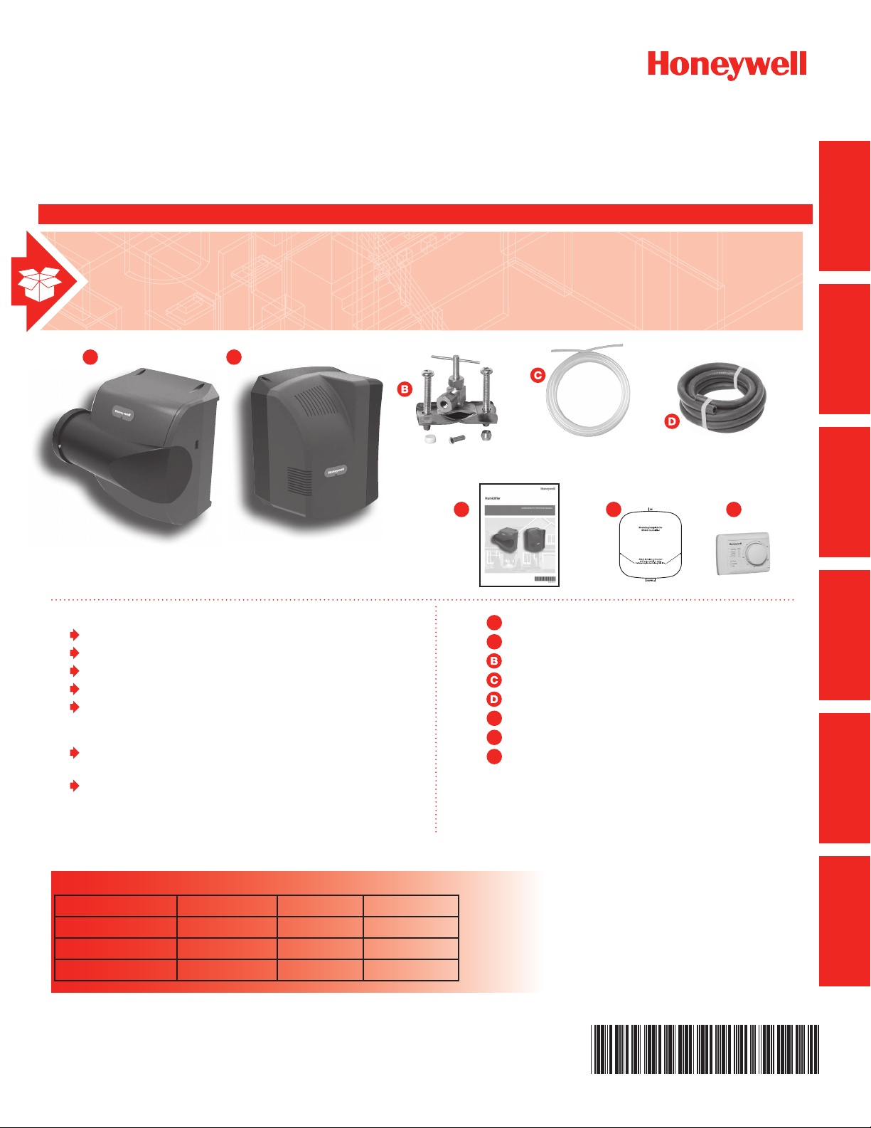
INCLUDED IN THIS HUMIDIFIER BOX
STARTED
GETTING
MOUNTING PLUMBING WIRING APPENDICES
1
A
2
A
Tools needed to install humidifier
Wire cutter/stripper
Tin snips or sheet metal cutter
#8 hex nut driver
Standard screwdriver
18-gauge wire (up to 5 conductor)
Other Requirements
If floor drain is not available, refer to Appendix B for
additional plumbing parts consideration.
If installed in or above a finished space, Honeywell
recommends installing a drip pan with water
sensor shut-off.
E
Humidifier Bypass
1
A
Humidifier Fan
2
A
Saddle valve
Water supply line
Drain hose (10 feet)
Owner’s manual
E
Mounting template
F
H8908 manual humidity control
G
F G
M32930
AND SERVICE
OPERATION
Hardware (not pictured)
Additional accessories included in select
models
Cross Reference Table
Humidifier Honeywell® Aprilaire® GeneralAire®
HE100 and HE150 HE225 500 570
HE200 and HE250 HE265 600 900
HE300 HE365 700 1000
Page 2

Page 3

Humidifier
GETTING STARTED
Safety Definitions and Precautions .............. 2
What to Expect From Your Humidifier ............ 3
Important Installation Requirements ............. 4
MOUNTING
Choosing a Mounting Method .................. 5
STEP ONE: Select the Mounting Location ...... 6
STEP TWO: Install Mounting
Template to the Duct .................... 6
Bypass Model Installation ..................... 7
STEP THREE: Configure
Humidifier Bypass ...................... 7
STEP FOUR: Installation ................... 8
STEP FIVE: Bypass Duct Installation .......... 9
Fan Model Installation ....................... 10
STEP THREE: Installation ................. 10
Humidifier Control Installation ................. 11
OPTION ONE: Duct Installation
H8908 Humidistat ..................... 11
OPTION TWO: Remote Installation
H8908 Humidistat ..................... 12
WIRING
Before Wiring Humidifier ..................... 15
STEP ONE: Remove the Humidifier Cover .... 15
STEP TWO: Understand the Wiring Terminals .. 15
STEP THREE: Understand the DIP Switches .. 16
STEP FOUR: Install the Transformer
(Bypass Models Only) .................. 16
STEP FIVE: Wiring Humidifier .............. 16
Wiring Configuration: Advanced Models
(HE150/HE250/HE300) ...................... 17
Wiring Configuration: Basic Models
(HE100/HE200) ............................ 19
OPERATION AND SERVICE
Startup and Checkout ....................... 21
Routine Maintenance ........................ 22
Troubleshooting ............................ 23
APPENDICES
A: Specifications ........................... 24
B: Advanced Draining ....................... 25
C: Parts List ............................... 26
STARTED
GETTING
MOUNTING PLUMBING WIRING APPENDICES
PLUMBING
Water Supply and Drain Connections ........... 13
STEP ONE: Connect the Water Supply ....... 13
STEP TWO: Tap into a Water Line ........... 13
STEP THREE: Connect to the Water Drain .... 14
NEED HELP? For assistance with this product please visit http://yourhome.honeywell.com
?
or call Honeywell Customer Care toll-free at 1-800-468-1502.
Read and save these instructions.
® U.S. Registered Trademark. Patents pending. Copyright © 2011 Honeywell International Inc. All rights reserved.
AND SERVICE
OPERATION
Humidifier 69-2413EF—05
1
Page 4

GETTING
STARTED
Safety Definitions and Precautions
Safety Definitions
These safety terms identify information you must read prior to installing or operating the humidifier.
CAUTION: Indicates a hazardous situation which, if not avoided, could cause bodily injury
or property damage.
WARNING: Indicates a hazardous situation which, if not avoided, could result in death or serious injury.
Safety Precautions
Make sure you read and understand the following safety hazards before installing, using, or working with the
humidifier:
CAUTION: Voltage Hazard.
Can cause electrical shock or equipment damage.
Disconnect HVAC equipment and any electrical outlet being used for the humidifier installation.
WARNING: Electrocution and Water Hazard.
Can cause death, blindness, and water damage to the home and HVAC Equipment.
CAUTION: Condensation, Fire, and Freezing Water Hazard.
Can cause failure of fan or limit control or result in water damage to home.
2
Humidifier 69-2413EF—05
Page 5

What to Expect From Your Humidifier
The installer should review these points with the homeowner and answer any questions they have before leaving
the job site.
• Achieving Humidity Setpoint. It may take up to a week of continuous operation to achieve the humidity
setpoint, especially if the home is dry when the humidifier is installed. This also depends on such factors as
weather, size of home, furnishings in the home, and insulation.
• Ideal Humidity. Home building industry experts cite 35% relative humidity as ideal for comfort and
safeguarding the home during the typical dry season. Homeowners can adjust to their own comfort or until
there is condensation on the windows. Lower the setpoint if condensation appears.
• Unit Not Humidifying. If the humidifier is not running but the humidity is below the setpoint, the humidity
control may have a frost protection setting to prevent window condensation from appearing.
• Home Ventilation. Excessive ventilation sends moist air outside and replaces it with dry air. This can make it
hard to maintain the humidity setpoint. If installing a ventilator, use a solution that retains moisture. An Energy
Recovery Ventilator (ERV) is recommended.
STARTED
GETTING
• Cleaning Requirements. At least once per year it is recommended to change the humidifier pad and clean
the water trays of the humidifier. See Operation and Service section for details.
• Energy Consumption. It is important to explain that with any humidification solution there is a cost
associated with converting water to humidity. The humidifier utilizes the air heat and air flow in your ducting to
make this conversion, which has gas and/or electric costs that depend on your HVAC system type and setup.
Humidifier 69-2413EF—05
3
Page 6

GETTING
STARTED
Important Installation Requirements
Failure to comply with these requirements will result in voided warranty, improper installation, and
service callbacks.
Personal Safety
• Wear safety glasses while installing the humidifier.
• Do not cut into any air conditioning or electrical line.
• Follow professional safety standards and all local regulations for plumbing, electrical, and mechanical
considerations.
Mounting Location
• Mount the humidifier in a level position to avoid water damage and ensure maximum output.
• Location must have access to a water line, drain, and power.
• Do not install the humidifier where the ambient temperature is lower than 34°F (1.1°C) or higher than 90°F
(40°C).
• Mounting area must be strong enough to support humidifier weight (up to 16 lbs [Fan] or 10 lbs [Bypass]).
• Do not mount directly to ductboard.
• If used near a pool or spa, make sure the humidifier can not fall into the water or be splashed.
• Ensure that the top and bottom covers of the humidifier can be removed and that the pad is accessible from
the chosen location.
Water Supply and Drainage
• Consult local plumbing codes for drain size, material, and maximum temperature allowed.
If Replacing an Old Bypass Humidifier
The humidifier is not identical in size and shape to other Honeywell bypass humidifiers. Before performing a
retrofit installation, you might need to:
• Dry-fit the humidifier to the existing ducting, plumbing, and wiring before fastening it to the duct to ensure that
the existing connections will reach the humidifier.
• If the duct opening of the old humidifier is not the right size for the humidifier, choose a new location or cover
the old opening with a piece of sheet metal and cut a new opening specifically for the humidifier using the
template provided.
Cross Reference Table
Humidifier Honeywell® Aprilaire® GeneralAire®
HE100 and HE150 HE225 500 570
HE200 and HE250 HE265 600 900
HE300 HE365 700 1000
4
Humidifier 69-2413EF—05
Page 7
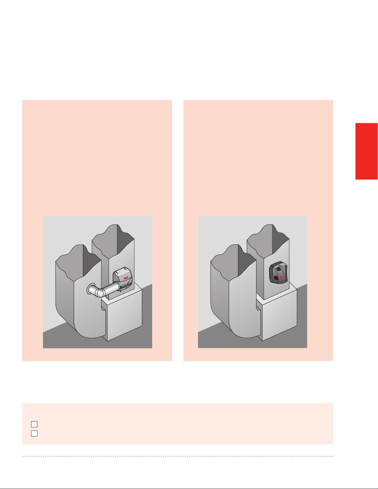
Choosing a Mounting Method
Whether you purchased a Bypass or Fan humidifier will determine how your humidifier will be installed:
Which humidifier do you have?
Bypass:
Bypass humidifiers use the pressure difference
between the supply and return to move duct
air through the humidifier. Access to both the
supply and return are required. The bypass
humidifier can be positioned on either the
supply or return duct.
Fan:
Fan humidifiers use the fan inside the humidifier
to pull duct air through the humidifier. Honeywell
strongly recomends mounting the HE300 on
the supply duct for maximum humidification
capacity. If a return duct installation is required,
a trap must be installed in the drain line. A hard
trap is recommended, but a coil in the line,
secured with tape or zip tie, is also acceptable.
See Water Supply and Drain Connections
section for details.
MOUNTING
MCR29871
Before beginning Mounting:
I have confirmed local codes for proper plumbing practices.
I have chosen an installation location that meets the requirements on page 4.
Humidifier 69-2413EF—05
MCR29929
5
Page 8
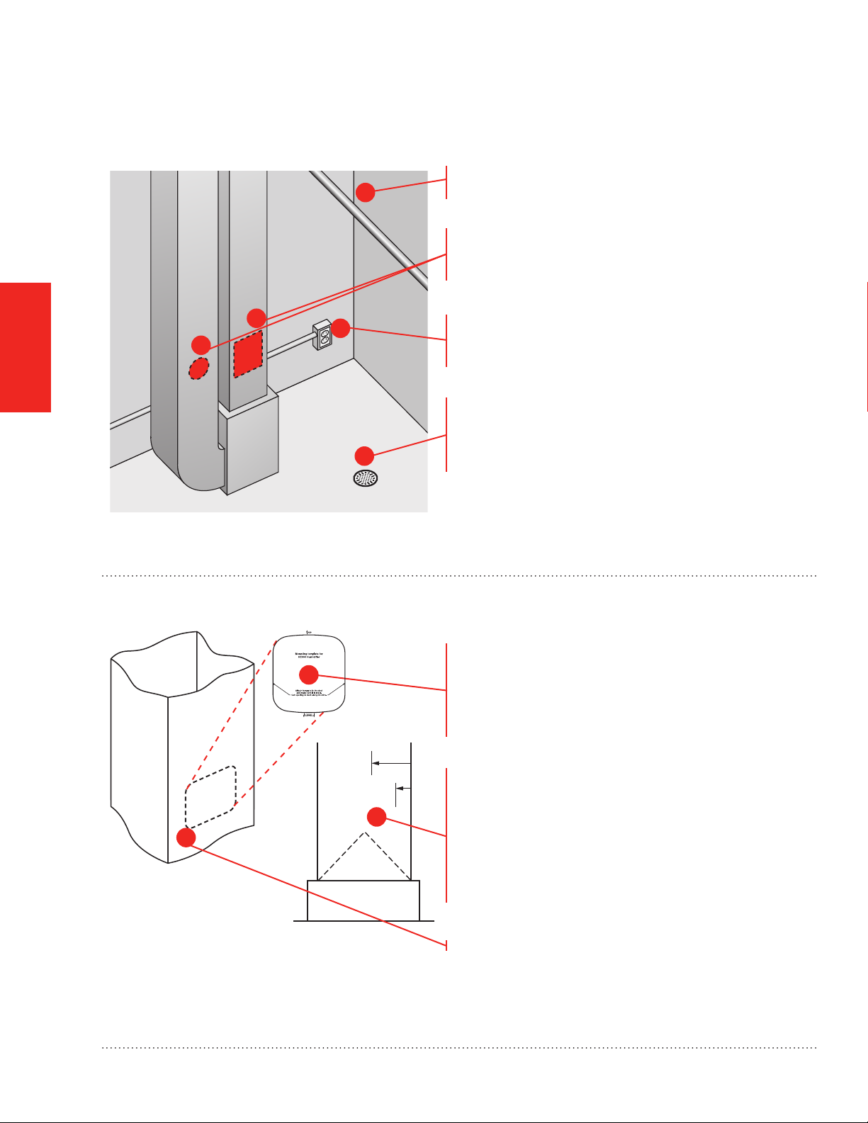
STEP ONE: Select the Mounting Location
MCR29877
1
Choose a location that has access to a water supply
pipe. Cold or hot water can be used.
Select a vertical or horizontal surface on the HVAC
duct work, with adequate space clearances, where
the humidifier can be mounted.
MOUNTING
2
3
2
Location must also have access to 120 VAC power.
For the HE300 Fan humidifier, the power cord is 6 feet
long.
Ensure the location is near a drain. Consult local
plumbing codes for proper drainage. If no main
4
floor drain is available, see “Appendix B: Advanced
Draining.”
STEP TWO: Install Mounting Template to the Duct
Position the template on the duct.
1
M32930
• Make sure the template is level and in the desired
position on the duct. Peel adhesive backing
and press template firmly into place in desired
mounting location.
1-3/4
FAN
(44)
BYPASS
1/2
(13)
2
3
M29873
A-COIL
Ensure proper clearances from the air-conditioning
coil inside the duct.
NOTE: The HE300 Fan model extends into the duct
1-3/4 inch. Bypass models extend into the duct 1/2
inch. Ensure clearance inside the duct.
• For best performance, maintain at least 24 inches
downstream of open air space inside the duct.
M29874
Cut the sheet metal, following the template outline.
6
Humidifier 69-2413EF—05
Page 9
If you are installing HE300 Fan model, proceed to page 10.
Bypass Model Installation
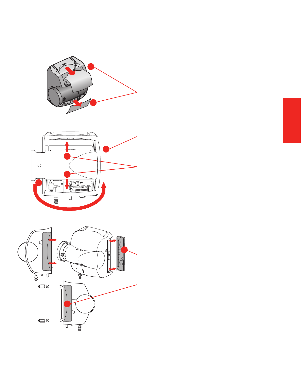
STEP THREE: Configure Humidifier Bypass
1
Configure the humidifier bypass outlet to the side that
best fits the application.
If the bypass needs to be on the other side, remove
the top and bottom covers
1
MOUNTING
MCR29875
Unplug the damper wire and plug in on the other side
(HE150/HE250 only).
2
3
3
Pull the bypass clamps apart from center to remove
the bypass; snap it back into place with the outlet on
the desired side.
2
MCR29876
Ensure that the pad is accessible. The handle of
the pad holder and side panel of the humidifier can
be switched so the pad holder can be removed
(opposite side of the bypass duct opening).
4
To remove the handle for the pad holder, slide it
toward the back of the humidifier, then pull it away
from the humidifier.
To remove the opposite side panel, place a
screwdriver into the two slots on the back of the
humidifier, and pop the panel off.
5
Snap the pad holder handle and side panel back into
place in the desired configuration.
MCR29946
Humidifier 69-2413EF—05
7
Page 10
Bypass Model Installation
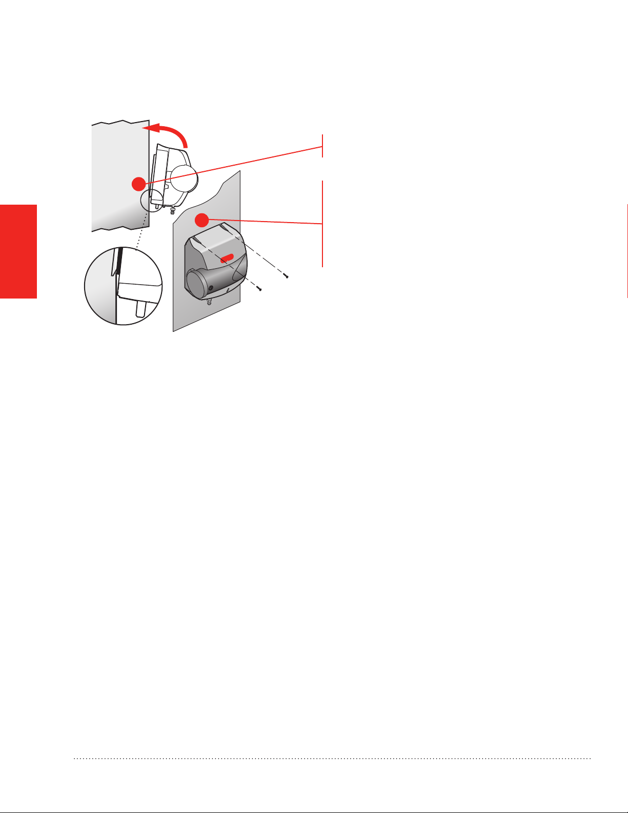
STEP FOUR: Mounting
Secure the support hooks on Bypass models to the
bottom lip of the hole.
MOUNTING
1
2
MCR29870
Push the top of the humidifier back against the duct.
Verify the humidifier is level and fasten the humidifier
to the duct using two self-drilling sheet metal screws
provided.
8
Humidifier 69-2413EF—05
Page 11
Bypass Model Installation
STEP FIVE: Bypass Duct Installation
On the duct opposite the humidifier Bypass install, cut
a 6-in. diameter duct hole.
• If the humidifier is on the supply duct, the 6-in.
diameter hole should be on the return.
• If the humidifier is on the return duct, the 6-in.
diameter hole should be on the supply.
1
Secure a 6-in. round duct starter collar into the 6-in.
2
MCR29933
duct hole.
Use rigid or aluminized flexible 6-in. duct to connect
the starter collar to the humidifier bypass port.
MOUNTING
2
Secure the duct to the humidifier port with self-drilling
sheet metal screws using the pre-drilled holes on the
bypass port. For added seal, wrap sheet metal tape
1
around the duct to port connection point.
2
MCR29878
Bypass mounting is complete. Go to page 11.
Before proceeding to the next step:
I secured the humidifier to the duct as instructed.
Humidifier 69-2413EF—05
9
Page 12
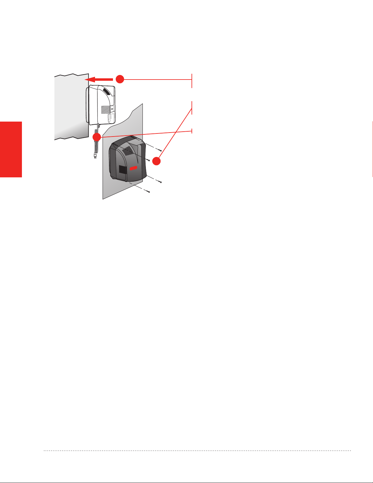
Fan Model Installation
STEP THREE: Mounting
MOUNTING
1
Slide the Fan model evenly into the duct hole. Verify
the humidifier is level.
Fasten the humidifier to the duct using four self-drilling
sheet metal screws provided.
Do not plug the humidifier in yet.
3
2
MCR29934
10
Humidifier 69-2413EF—05
Page 13
Humidifier Control Installation
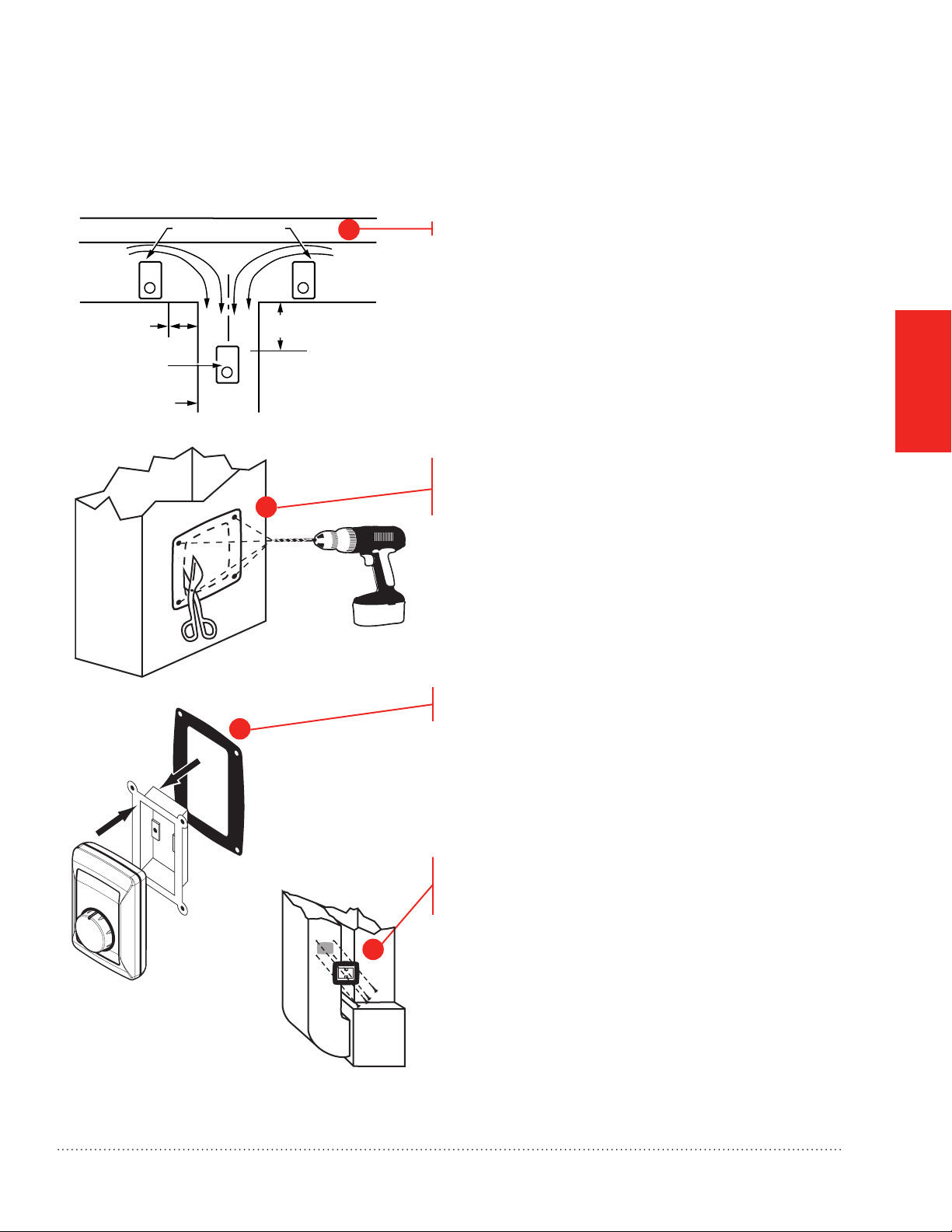
OPTION ONE: Duct Installation of H8908 Humidistat (provided)
If a different control is being used, refer to installation instructions provided with that control.
RETURN
AIR
6 in. (152 mm)
MINIMUM
BEST
LOCATION
RETURN AIR DUCT
ALTERNATE LOCATION
2
15 in. (381 mm)
MINIMUM
1
RETURN
AIR
M13369
Choose a location on the duct.
MOUNTING
Apply sticker template to duct and drill holes for
mounting screws. Cut along the dotted line of the
template with metal shears or tin snips.
M24800
M24733
Remove the base bracket from the humidistat. Slide
3
the black gasket onto the base bracket.
Secure the base bracket to the duct.
Secure to the duct with four 1-in. (25 mm)
screws (provided).
4
M29879
Humidifier 69-2413EF—05
11
Page 14
Humidifier Control Installation
OPTION TWO: Remote Installation of H8908 Humidistat (provided)
If a different control is being used, refer to installation instructions provided with that control.
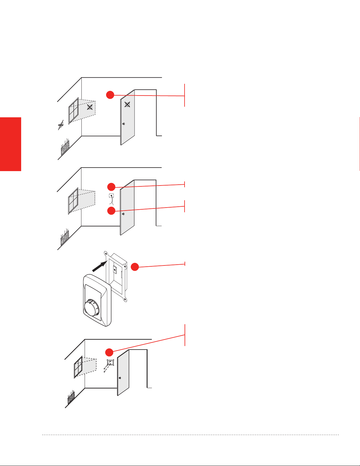
Choose a location in the living area. Select a location
1
clear of drafts or excessive humidity. Avoid mounting
near doors or windows, or in bathrooms or kitchens.
MOUNTING
M29952
2
Cut 1-in. diameter wire hole in wall.
Run two-fan, low-voltage wire to the mounting location
2
M24721
3
in the living area.
Remove the base bracket from the humidistat.
12
M29948
Secure the base bracket to the remote location with
two 1-in. (25 mm) screws (provided).
4
M29949
Humidifier 69-2413EF—05
Page 15
Water Supply and Drain Connections
STEP ONE: Connect the Water Supply
Use hot or cold water.
Cut the water line so it reaches from the humidifier to
1
the main water supply tap
Insert the water line into the gray quick connect
fitting. Insert it fully, and apply modest pull pressure to
ensure a tight fit.
2
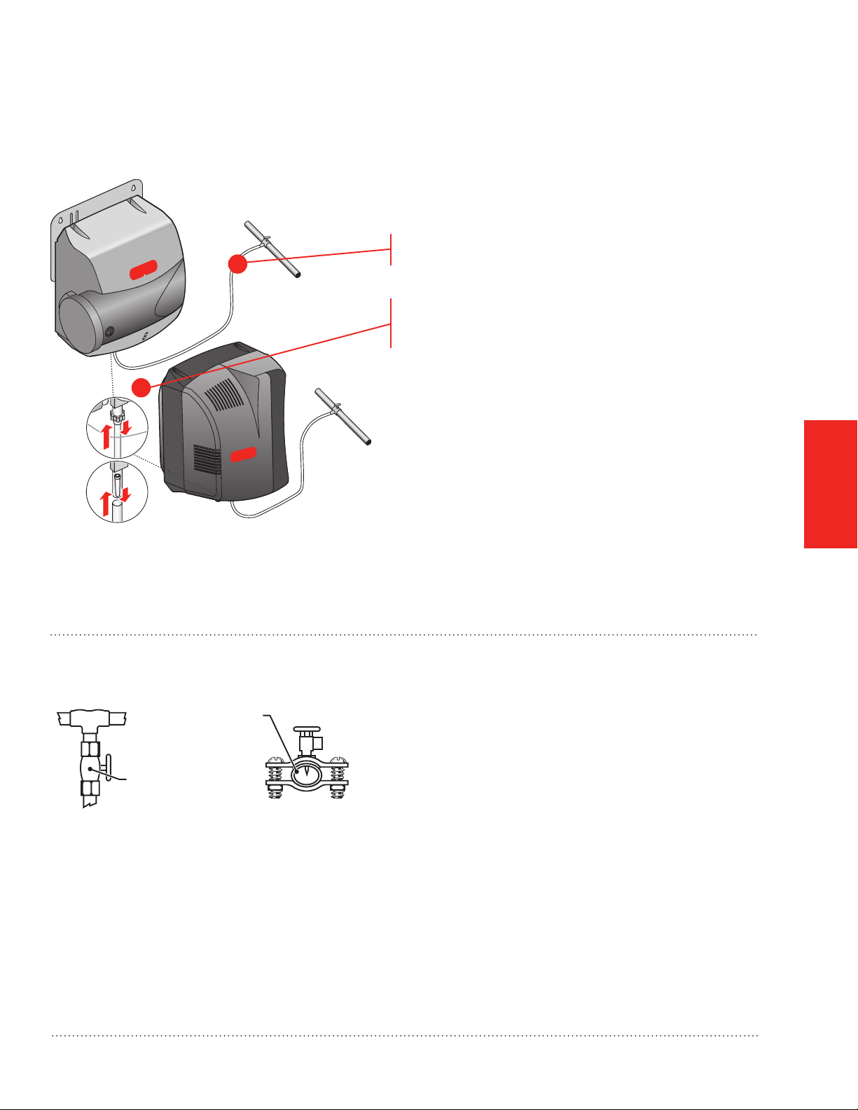
STEP TWO: Tap into a Water Line
Water Supply
Line
Manual Shutoff
Valve
T-fitting
Saddle Valve
MCR32931
M29605
Note: The quick connect fitting can be removed if you
prefer to use a standard 1/4-in. brass compression
nut plumbing connection. Do not remove the conical
screen if you select this option.
• Consult local codes for proper plumbing.
• Use the saddle valve provided or a T-fitting and
manual shutoff valve to tap into the water line.
• Refer to the literature included with the valve you
chose and the local plumbing codes. Use proper
technique for the valve.
• Connect the other end of the humidifier water line
to the water valve.
PLUMBING
Humidifier 69-2413EF—05
13
Page 16

STEP THREE: Connect to the Water Drain
• Consult and follow local plumbing codes for drain
pipe size and flow requirement.
• The ideal installation is directly to the main floor
drain using the rubber hose provided.
• If direct floor drain access is not available, see
“Appendix B: Advanced Draining.”
PLUMBING
1
2
3
4
MCR29881
HE300 ONLY: Return Duct Installation
Connect the 1/2-in. drain hose provided to the drain
fitting on the bottom of the humidifier.
Use the hose clamp provided to secure the drain hose
to the fitting.
Route the drain hose to the floor drain. The hose must
have a continuous downward slope.
Direct the hose outlet into the floor drain. Secure
the hose to reduce the risk of water pooling or
splashing as it drains from the humidifier.
If a return duct installation is required, a trap
must be installed in the drain line. A hard trap is
recommended, but a coil in the line, secured with tape
or zip tie, is also acceptable.
14
M32929
Before proceeding to Wiring:
I have connected the water supply line to the humidifier and the main water tap.
I have installed the drain connection.
I have checked all plumbing connections for leaks.
Humidifier 69-2413EF—05
Page 17
Before Wiring the Humidifier
CAUTION: Voltage Hazard.
Be sure the humidifier is not plugged in before beginning wiring.
Before wiring the humidifier:
I understand and will comply with applicable local wiring codes and regulations.
I will read the section “Using the DIP Switches” beginning on the next page.
What humidifier model do I have?
The model number can be found on the bottom of the humidifier.
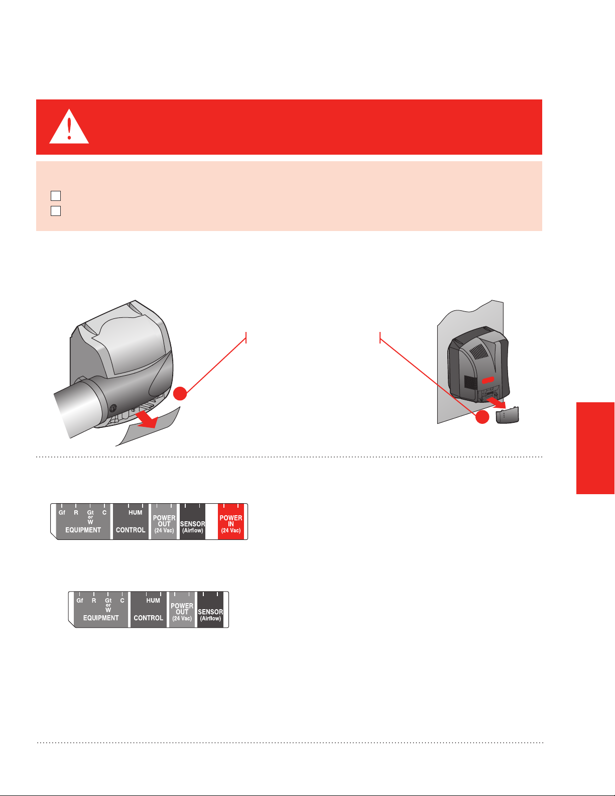
STEP ONE: Remove the Humidifier Cover
Remove the bottom cover.
1a
MCR29935
STEP TWO: Understand the Wiring Terminals (HE150/HE250/HE300 only)
HE150/HE250 Bypass Terminal
Gf: Used to force system fan on when humidity is
needed.
MCR29937
HE300 Fan Terminal
M29936
R: Input from system R. Needed to power Gf when
forcing fan on.
Gt or W: Input from system G or W. Needed to
humidify only during fan or heat calls by system.
HUM: Powered contacts for humidity control.
C: Common. Needed for Gt or W input. Connect to
system C.
Power Out: 24V power for electric controls.
Power In: Power from 15VA transformer on HE150/
HE250 only.
SENSOR: Powered contacts for an air proving device
when utilized.
1b
MCR29950
WIRING
Humidifier 69-2413EF—05
15
Page 18
Using the DIP Switches (HE150/HE250/HE300 only)
Two features are configured by DIP settings, which are described inside the humidifier cover.
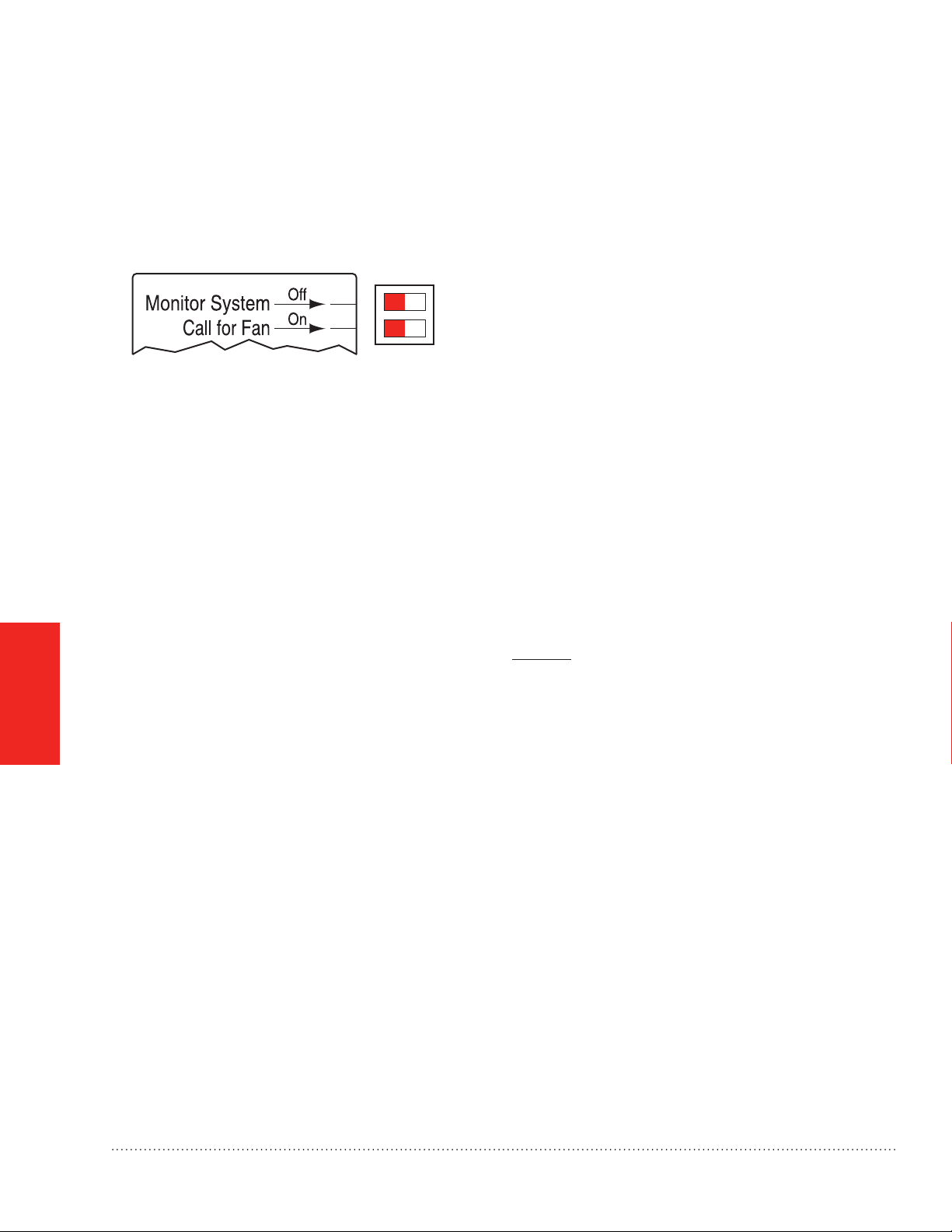
STEP THREE: Understand the DIP Switches
DIP 1 (Top): This switch looks for inputs from the
HVAC system before allowing humidity. Set to the left,
the humidifier will look for input(s). Set to the right, it
MCR29882
will not.
DIP 2 (Bottom): This switch controls the fan. Set to
the left, the HVAC system controls the fan. Set to the
right, the humidifier will force the fan on when there is
a call for humidity.
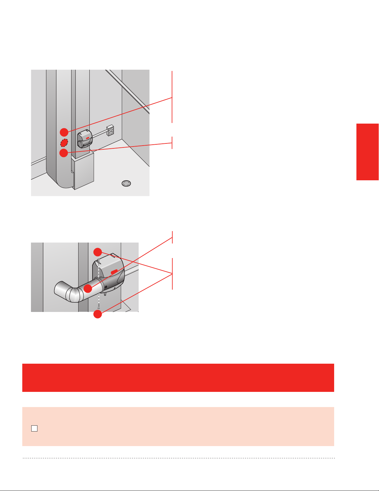
STEP FOUR: Install the Transformer (Bypass Models Only)
Install transformer on the outside of a grounded metal junction box using only a 7/8 in. (22 mm) knockout hole.
Place mounting tabs into the knockout hole and firmly tighten the locking screw. Field wiring connections and
grounding means for the transformer and enclosure shall be in accordance with the National Electrical Code
(NEC) and the Canadian Electrical Code (CEC). Connect wires to the 120V side of the transformer.
WIRING
For HE150 and HE250, the 15V transformer must provide constant power to the 24V IN terminals.
STEP FIVE: Wiring the Humidifier
Use a wiring diagram from the following pages that matches your equipment.
When wiring is complete, run the wires coming out of the humidifier into the wiring clip on the bottom of the
humidifier.
16
Humidifier 69-2413EF—05
Page 19

Wiring Configuration: Advanced Models (HE150/HE250/HE300)
HE150 OR HE250
HE300
HE150 OR HE250
HE300
Wiring H8908 to humidify only with a call for heat or fan.
2
G OR W
C
OR
AIR PROVING
DEVICE
3
H8908
30
20
10
OFFON
40
50
60
1
POWER IN
1
2
G OR W
OR
C
AIR PROVING
DEVICE
H8908
40
30
50
20
10
60
OFF ON
POWER IN
DIP SWITCH SETTING
RESET POWER AFTER
HE150/HE250 USES A 15 VA TRANSFORMER WIRED INTO 24V IN.
1
HE100/HE200 USES A 10 VA TRANSFORMER WIRED INTO 24V IN.
2
CONNECT G TO HUMIDIFY WHEN THERE IS A FAN CALL.
CONNECT W TO HUMIDIFY WHEN THERE IS A HEAT CALL.
NEVER CONNECT BOTH. CONNECT C WHEN USING G OR W.
USE AIR PROVING DEVICE INSTEAD OF THE G/W CONNECTION
3
TO HUMIDIFY ANY TIME THE FAN IS OPERATING.
ANY DIP SWITCH CHANGES
HE300 USES A LINE CORD PLUG.
1
2
CONNECT G TO HUMIDIFY WHEN THERE IS A FAN CALL.
CONNECT W TO HUMIDIFY WHEN THERE IS A HEAT CALL.
NEVER CONNECT BOTH. CONNECT C WHEN USING G OR W.
USE AIR PROVING DEVICE INSTEAD OF THE G/W CONNECTION
3
TO HUMIDIFY ANY TIME THE FAN IS OPERATING.
Wiring TrueIAQ, VisionPRO IAQ, or Prestige, using the intelligent control to program humidity calls with heat,
cool, or on demand.
3
M29938A
WIRING
FROM
HUMIDITY
CONTROL
HE150/HE250 USES A 15 VA TRANSFORMER WIRED INTO 24V IN.
1
HE100/HE200 USES A 10 VA TRANSFORMER WIRED INTO 24V IN.
Humidifier 69-2413EF—05
1
POWER IN
POWER IN
DIP SWITCH SETTING
RESET POWER AFTER
ANY DIP SWITCH CHANGES
FROM
1
HUMIDITY
CONTROL
HE300 USES A LINE CORD PLUG.
1
M29939A
17
Page 20

Wiring Configuration: Advanced Models (HE150/HE250/HE300)
HE150 OR HE250
HE300
HE150 OR HE250
HE300
Wiring to force the HVAC system fan on whenever humidity is needed (on demand).
POWER OUT
G (THERMOSTAT)
1
24V FOR
ELECTRONIC
HUMIDISTAT
R
G (FURNACE)
ONLY NEEDED IF SYSTEM’S THERMOSTAT DOES NOT ISOLATE Y FROM G.
1
IF NEEDED, BREAK THE THERMOSTAT G TO SYSTEM G CONNECTION
AND ROUTE THROUGH HUMIDIFIER AS SHOWN.
2
HE150/HE250 USES A 15 VA TRANSFORMER WIRED INTO 24V IN.
HE100/HE200 USES A 10 VA TRANSFORMER WIRED INTO 24V IN.
FROM
HUMIDITY
CONTROL
2
POWER IN
ANY DIP SWITCH CHANGES
Wiring to force fan on and prove airflow in the duct.
POWER IN
DIP SWITCH SETTING
RESET POWER AFTER
POWER OUT
G (THERMOSTAT)
1
24V FOR
ELECTRONIC
HUMIDISTAT
R
FROM
HUMIDITY
CONTROL
G (FURNACE)
2
ONLY NEEDED IF SYSTEM’S THERMOSTAT DOES NOT ISOLATE Y FROM G.
1
IF NEEDED, BREAK THE THERMOSTAT G TO SYSTEM G CONNECTION
AND ROUTE THROUGH HUMIDIFIER AS SHOWN.
2
HE300 USES A LINE CORD PLUG.
M29940A
WIRING
POWER OUT
G (THERMOSTAT)
1
24V FOR
ELECTRONIC
HUMIDISTAT
R
FROM
HUMIDITY
CONTROL
G (FURNACE)
ONLY NEEDED IF SYSTEM’S THERMOSTAT DOES NOT ISOLATE Y FROM G.
1
IF NEEDED, BREAK THE THERMOSTAT G TO SYSTEM G CONNECTION
AND ROUTE THROUGH HUMIDIFIER AS SHOWN.
HE150/HE250 USES A 15 VA TRANSFORMER WIRED INTO 24V IN.
2
HE100/HE200 USES A 10 VA TRANSFORMER WIRED INTO 24V IN.
AFS
2
POWER IN
G (FURNACE)
2
POWER IN
DIP SWITCH SETTING
RESET POWER AFTER
ANY DIP SWITCH CHANGES
POWER OUT
G (THERMOSTAT)
1
24V FOR
ELECTRONIC
HUMIDISTAT
AFS
R
ONLY NEEDED IF SYSTEM’S THERMOSTAT DOES NOT ISOLATE Y FROM G.
1
IF NEEDED, BREAK THE THERMOSTAT G TO SYSTEM G CONNECTION
AND ROUTE THROUGH HUMIDIFIER AS SHOWN.
HE300 USES A LINE CORD PLUG.
2
FROM
HUMIDITY
CONTROL
M29941A
18
Humidifier 69-2413EF—05
Page 21

Wiring Configuration: Advanced Models (HE150/HE250/HE300)
HE150 OR HE250
HE300
Wiring TrueEASE to equipment with powered terminals.
4 4
COM HUM R G
1 1
AFS
3
POWER IN
2
3
COM HUM R G
POWER IN
ADD 24VAC ISOLATION RELAY (SUCH AS R8222B1067) BETWEEN
1
THE HUMIDIFIER AND THE AIR HANDLER.
THE 50027910-001 AIR-FLOW SWITCH (AFS) IS RECOMMENDED
2
TO ENSURE AIR FLOW WHEN THE HUMIDIFIER IS RUNNING. IF
THE AFS IS USED, SET DIP SWITCH 1 TO OFF (LEFT).
3
HE150/HE250 USES A 15 VA TRANSFORMER WIRED INTO 24V IN.
HE100/HE200 USES A 10 VA TRANSFORMER WIRED INTO 24V IN.
WIRING DIAGRAM ASSUMES THE USE OF EQUIPMENT-SPECIFIC
4
COMMUNICATING THERMOSTAT CONTROLLING THE HUMIDIFIER.
DIP SWITCH SETTING
RESET POWER AFTER
ANY DIP SWITCH CHANGES
ADD 24VAC ISOLATION RELAY (SUCH AS R8222B1067) BETWEEN
1
THE HUMIDIFIER AND THE AIR HANDLER.
THE 50027910-001 AIR-FLOW SWITCH (AFS) IS RECOMMENDED
2
TO ENSURE AIR FLOW WHEN THE HUMIDIFIER IS RUNNING. IF
THE AFS IS USED, SET DIP SWITCH 1 TO OFF (LEFT).
3
HE300 USES A LINE CORD PLUG.
WIRING DIAGRAM ASSUMES THE USE OF EQUIPMENT-SPECIFIC
4
COMMUNICATING THERMOSTAT CONTROLLING THE HUMIDIFIER.
Wiring Configuration: Basic Models (HE100/HE200)
AFS
2
M33040
WIRING
Wiring TrueEASE to equipment with powered terminals.
COM
HUM
R
G
WIRING DIAGRAM ASSUMES THE USE OF EQUIPMENT-SPECIFIC
1
COMMUNICATING THERMOSTAT CONTROLLING THE HUMIDIFIER.
HUMIDIFIER
1
WATER
SOLENOID
LEAD WIRE
M33039
Humidifier 69-2413EF—05
19
Page 22

Wiring Configuration: Basic Models (HE100/HE200)
HUMIDIFIER
HUMIDIFIER
Wiring H8908 with fan interlock.
PROVIDE DISCONNECT MEANS AND
1
OVERLOAD PROTECTION AS REQUIRED.
24 VAC WIRING.
L1
(HOT)
L2
1
2
POWER
SUPPLY
TRANSFORMER
FAN CONTROL
FURNACE
FAN
MOTOR
H8908
30
20
10
OFFON
40
50
60
2
WATER
SOLENOID
LEAD WIRE
M29945A
WIRING
Wiring H8908 with 2-speed fan motor.
1
POWER SUPPLY. PROVIDE DISCONNECT
MEANS AND OVERLOAD PROTECTION AS
REQUIRED.
2
24 VAC WIRING.
L1
(HOT)
L2
POWER
SUPPLY
1
FAN CONTROL
DPST
SWITCHING
RELAY
HL
C
2-SPEED
FAN
MOTOR
TRANSFORMER
2
H8908
30
20
10
OFFON
40
50
60
WATER
SOLENOID
LEAD WIRE
M29942A
20
Humidifier 69-2413EF—05
Page 23

Wiring Configuration: Basic Models (HE100/HE200)
H8908
HUMIDIFIER
Wiring H8908 with current-sensing relay.
30 40
50
20
10
60
OFFON
TRANSFORMER
L2
CURRENT
SENSING
RELAY
1
POWER SUPPLY. PROVIDE DISCONNECT
MEANS AND OVERLOAD PROTECTION AS
REQUIRED.
24V WIRING.
2
LO
C
HI
2
L1
(HOT)
HUMIDIFIER
1
WATER
SOLENOID
LEAD WIRE
M29943A
WIRING
Wiring H8908 in line with air proving device.
AIR PROVING
DEVICE
2
TRANSFORMER
1
L1
L2
(HOT)
POWER SUPPLY. PROVIDE DISCONNECT MEANS
1
AND OVERLOAD PROTECTION AS REQUIRED.
24V WIRING.
2
H8908
30 40
20
10
OFFON
50
60
WATER
SOLENOID
LEAD WIRE
M29944A
Humidifier 69-2413EF—05
21
Page 24

Startup and Checkout
When installation is complete, follow the steps below. Make sure the humidifier is running properly before turning
the system over to the homeowner. Once the humidifier is running, day-to-day operation is automatic. The
homeowner can use the control to adjust the humidity levels and turn the humidifier on or off.
Snap the bottom cover into place.
OPERATION
AND SERVICE
1
2
3
4
5
6
MCR29884
Turn on the water supply at the saddle valve or
T-fitting and manual shutoff valve. Water will flow to the
humidifier but will not pass through the pad until the
humidity control is turned on.
Plug in the humidifier (HE300) or apply HVAC system
power (HE100/HE150/HE200/HE250)
• On advanced models, the LED lights will blink for
3-5 seconds to verify that there is system power.
On HE100/HE200, turn the Damper Position knob on
the bypass outlet so that it is parallel to the bypass
outlet. On HE150/HE250, the humidifier does this
automatically. Not applicable for HE300.
Turn the humidity control to On.
• If your wiring is configured for operation only with
heat or fan, make the appropriate system demands
to allow humidification.
• Make sure air is blowing through the ductwork with
the humidifier call.
The Humidifying light will be solidly on when water is
flowing through the humidifier pad
• On HE150/HE250 models, remove the humidifier’s
top cover to verify water flow through the top tray
and into the pad. Make sure that the damper
rotates open when humidity is on, and rotates
closed when humidity is off.
• On HE300 models, verify water is exiting the drain
hose.
22
Check all water line and drain connections to ensure there are no leaks before leaving the job site.
• Check for leaks immediately after turning the main water supply on, and again after 15 minutes of humidifier
operation.
Turn the setpoint to the homeowner’s desired level when testing is complete. If humidity is not needed, set the
control to Off, and turn the Damper Position knob on the bypass outlet so that it is perpendicular to the bypass
outlet (HE100/HE200 only).
Humidifier 69-2413EF—05
Page 25

Routine Maintenance
MCR29886
It is recommended that the humidifier pad be replaced once per year. This can be done at the beginning or the
end of the dry season. The humidifier design makes this annual replacement quick and easy, providing one-step
access to the pad.
Bypass:
1a. Pad can be replaced from the side by gripping
the black handle and pulling out, or from the
front by removing the humidifier’s top cover
and rocking the pad forward and out.
Humidifier pad might remove from other side
of humidifier, depending on installation.
25%
1
2
Fan:
1b. Pad can be replaced from the front by gripping
the black handle and pulling out.
MCR29885
2. Remove tray on top of the pad, and wipe free any sediment present within the tray.
3. Replace the old pad with the new, making sure pad is oriented correctly (see pad box). Wipe free any
sediment present inside the pad frame.
4. Reseat the tray on top of the pad with the arrows inside the tray pointing into the duct. Then reinsert the frame
into the humidifier.
5. Afer pad replacement is complete, remove the bottom cover and press the RESET button to reset the
maintenance timer.
Humidifier 69-2413EF—05
23
AND SERVICE
OPERATION
Page 26

Troubleshooting
Problem What To Look For What To Do
Low humidity Furnace blower not
operating
Rapid air changes or
drafts
High humidity Condensation on walls 1. Turn off humidity control and water until condensation is completely
Heavy condensation on
windows
Replace Pad
light is on
(HE150/HE250/
HE300)
Service light is on
(HE150/HE250)
This is the yearly
maintenance reminder to
replace the pad inside the
humidifier
The damper inside the
bypass has failed to open
completely
1. Reset circuit breaker or check for blown fuse.
2. Check that the furnace power is on.
3. Check all external wiring connections.
4. Check the humidity control setting.
1. Keep doors and windows closed.
2. Close fireplace damper when not in use.
3. Keep exhaust fan running time to a minimum.
4. Seal around doors and windows.
evaporated.
1. Turn humidity control down low enough to eliminate condensation
caused by moisture. If moisture persists, more ventilation is needed.
1. Refer to the parts list and replace the pad for your humidifier model.
2. Once pad is replaced, press the RESET button under the wire cover.
1. Press RESET button under the wire cover.
2. Verify the damper plug is connected on the side of the humidifier the
bypass outlet is on.
3. Ensure there is no interference from sheet metal screws that connect
the bypass to ducting.
4. If fault persists, replace bypass damper motor.
OPERATION
AND SERVICE
24
Service light is on
(HE300)
Air proving device has
detected a lack of air
movement
Only possible with DIPs
configured as:
The fan motor has failed 1. Press RESET button under the wire cover.
Air proving device has
detected a lack of air
movement
Only possible with DIPs
configured as:
1. Check wiring to Air Flow Switch.
2. Confirm DIP switch configuration and wiring on the humidifier is correct.
3. Check location of Air Flow Switch to ensure it is properly placed in duct
to detect air.
4. Check switch relays.
5. If fault persists, replace Air Flow Switch.
2. Unplug the humidifier and plug it back in.
3. If fault persists, replace motor assembly.
1. Check wiring to Air Flow Switch.
2. Confirm DIP switch configuration and wiring on the humidifier is correct.
3. Check location of Air Flow Switch to ensure it is properly placed in duct
to detect air.
4. Check switch relays.
5. If fault persists, replace Air Flow Switch.
Humidifier 69-2413EF—05
Page 27

A: Specifications
Humidifying Capacity
At 120°F (49°C) plenum temperature and 0.20 static pressure
drop across supply and return:
HE100/150: up to 12 gallons per day (gpd)
(46 liters per day [lpd])
HE200/250: up to 17 gpd (65 lpd)
HE300: up to 18 gpd (68 lpd)
Humidified Area
HE100/150: Up to 16,000 cubic feet
HE200/250: Up to 20,000 cubic feet
HE300: Up to 24,000 cubic feet
Dimensions
HE100/150: 14.5 in. W x 14 in. H x 10.1 in. D
(368 mm W x 356 mm H x 257 mm D)
HE200/250: 15 in. W x 17.15 in. H x 10.1 in. D
(381 mm W x 436 mm H x 257 mm D)
HE300: 15.5 in. W x 16.8 in. H x 10.3 in. D
(394 mm W x 427 mm H x 262 mm D)
Humidifier Pad Dimensions
HE100/150: 9-1/2 in. W x 9-13/16 in. H x 1-1/2 in. D
(241 mm W x 249 mm H x 38 mm D)
HE200/250: 10 in. W x 13 in. H x 1-1/2 in. D
(254 mm W x 330 mm H x 38 mm D)
HE300: 10 in. W x 13 in. H x 1-1/2 in. D
(254 mm W x 330 mm H x 38 mm D)
Static Pressure
HE100/150/: Supply plenum static pressure no greater
200/250 than .3 in. w.c.
HE300: Supply plenum static pressure no greater
than .4 in. w.c.
Plenum Opening Dimensions
HE100/150: 9-5/16 in. W x 9-7/16 in. H (238 mm W x 241 mm H)
HE200/250: 9-3/4 in. W x 12-5/8 in. H (248 mm W x 321 mm D)
HE300: 13-1/2 in. W x 14-1/16 in. H (343 mm W x 357 mm D)
Bypass Duct Opening Dimensions (HE100/150/200/250)
6 in. (152 mm)
Operating Ranges
34ºF–90ºF (1.1ºC–32ºC)
Humidity: 0–95% RH, non-condensing
Drain Fitting
1/2 in. (13 mm) I.D. plastic hose connected directly to drain
fitting on unit.
Electrical Ratings and Tolerances
HE100/200: 24VAC, 60 Hz, 0.5 A maximum
HE150/250: 24VAC, 60 Hz, 0.75 A maximum
HE300: 120VAC, 60 Hz, 1 A maximum
Humidifier 69-2413EF—05
25
AND SERVICE
OPERATION
Page 28

VENTED PER
FOR ALL OPTIONS SHOWN:
LOCAL CODE
ALL PLASTIC PIPE
JOINTS ARE WELDED
1-1/2 IN.
PVC
WELD
1-1/2 IN.
PVC TEE
THREADS
WELD
COUPLING
SOLENOID VALVE TO
DRAIN TRAP ARE SEALED
SINK
WELD
1-1/2 IN. MINIMUM TRAP
(OR SIZE PER LOCAL CODE)
ALL CONNECTIONS FROM
MCR29888
ALTERN ATIVE
THIS CONFIGURATION ALLOWS FOR
REMOVA L OF THE TRAP
1-1/2 IN. PVC
1/2 IN. MNPT X SWEAT
1/2 IN. FNPT X 1-1/2 IN. PVC
1/2 IN. MNPT X 1/2 IN. CPVC
1/2 IN. (MINIMUM) PVC PIPE
Option 2: Plumbing to a dedicated trap.
HOSE CLAMP
1/2 IN. FNPT X 1-1/2 IN. PVC
1/2 IN. BARB X 1/2 IN. MNPT
1/2 IN. FNPT X 1-1/2 IN. PVC
SIZE TO FIT PUMP OUTPUT
Option 4: Plumbing to sink trap.
1/2 IN. FNPT X SWEAT
1/2 IN. COPPER PIPE
1/2 IN. (MINIMUM)
1/2 IN. MNPT X SWEAT
1/2 IN. FNPT X 1-1/2 IN. PVC
1/2 IN. PVC
1/2 IN. FNPT X
1/2 IN. FNPT X 1/2 IN. CPVC
1/2 IN. (MINIMUM) PVC PIPE
FLEXIBLE
HOSE
1-1/2 IN. PVC
PVC PIPE
1/2 IN. MNPT X 1/2 IN. CPVC
1/2-IN. TUBING
RATED AT 140°F
1/2 IN. CPVC PIPE
HOSE FROM
HUMIDIFIER
HOSE CLAMP
1/2 IN. FNPT X 1-1/2 IN. PVC
140°F RATED PUMP
>5 GPH FLOW RATE
WITH 9-FT RISE
SIZE TO FIT PUMP OUTPUT
1/2 IN. BARB X 1/2 IN. MNPT
1/2 IN. FNPT X 1-1/2 IN. PVC
1-1/2 IN. PVC
STAINLESS STEEL
SLOTTED BAND
COUPLING SIZED TO
FIT PIPE (COPPER,
PVC, CPVC)
Connect to humidifier.
Common to all plumbing options.
• Support rubber hose every 6 in.
• PVC must be schedule 40 or higher rating.
• All plastic pipe joints are welded.
• Drain into a P-trap that will remain wetted at all times.
SEAL ALL CONNECTIONS FROM
SOLENOID VALVE TO DRAIN STACK
HOSE
CLAMPS
1/2 IN. BARB X 1/2 IN. MNPT
APPENDICES
26
B: Advanced Draining
WYE
WELD
1/2 IN. MNPT X 1/2 IN. CPVC
1/2 IN. FNPT X 1-1/2 IN. PVC
THREADS
WELD
THREADS
ALL PLASTIC PIPE UNDER
SINK 1-1/2 IN. MINIMUM PVC
HOSE CLAMP
3/8 IN. BARB X 3/4 IN. MNPT
3/4 IN. FNPT X 1-1/2 IN. PVC
SIZE TO FIT PUMP OUTPUT
ALTERN ATIVE
THIS CONFIGURATION ALLOWS FOR
REMOVA L OF THE TRAP
STAINLESS STEEL
SLOTTED BAND
COUPLING SIZED TO
FIT PIPE (COPPER,
1-1/2 IN. PVC
WELD
PVC, CPVC)
COUPLING
SINK
WELD
3/8-IN. TUBING
RATED AT 212°F
HOSE FROM
HUMIDIFIER
HOSE CLAMPS AT
TO PUMP
ALL CONNECTIONS
ALTERN ATIVE
3/4 IN. FNPT X 3/4 IN. CPVC
3/4 IN. CPVC PIPE
Option 1: Plumbing to drain with
condensate pump.
flow rate, with 9-foot rise).
• Pump with (140°F temperature rating, > 5 GPH pump
in a drip pan with wet switch wired to turn off humidifier.
• Pump must be powered when humidifier is operating.
• Use a pump with a built-in overflow sensor or install the pump
Option 3: Plumbing to sink with a
dedicated trap.
ALL CONNECTIONS FROM
SOLENOID VALVE TO
DRAIN TRAP ARE SEALED
1/2 IN. MNPT X SWEAT
1/2 IN. FNPT X 1-1/2 IN. PVC
1/2 IN. PVC
1/2 IN. (MINIMUM)
PVC PIPE
Humidifier 69-2413EF—05
Page 29

C: Parts List
5 6
3 4
15
13 14
8
7
9
22
x 25
23
x 25
M32932
18
21
16
111012
LOAD
R
20 21
C
Humidifier 69-2413EF—05
17
19
APPENDICES
M29951
27
Page 30

Figure
Reference
Part Number Part Description Use With Model
N/A HC26E1004 Large AgION coated replacement pad HE200, HE250. HE300
N/A HC26A1008 Large standard replacement pad HE200, HE250, HE300
N/A HC22E1003 Small AgION coated replacement pad HE100, HE150
N/A HC22A1007 Small standard replacement pad HE100, HE150
N/A 32001616-001 Saddle valve HE100, HE150, HE200,
HE250, HE300
1 50041883-002 AC Solenoid valve HE100, HE200
2 50041883-001 DC Solenoid valve HE150, HE250, HE300
3 50041861-001 Frame and tray assembly for small bypass model HE100, HE200
4 50041861-002 Frame and tray assembly for large bypass model HE150, HE250
5 50052641-001 Top cover for small bypass model HE100, HE150
6 50052641-002 Top cover for large bypass model HE200, HE250
7 50041888-001 Small bypass duct with manual damper HE100
8 50041888-002 Large bypass duct with manual damper HE200
9 50041890-001 Small bypass duct with automatic damper HE150
10 50041890-002 Large bypass duct with automatic damper HE250
11 50041886-001 Bottom cover for small basic bypass model HE100
12 50041887-001 Bottom cover for large basic bypass model HE200
13 50052642-001 Bottom cover for small advanced bypass model HE150
14 50052642-002 Bottom cover for large advanced bypass model HE250
15 50057547-002 HE150 circuit board HE150
50057547-003 HE250 circuit board HE250
16 50045729-001 Blower and motor assembly with isolator HE300
17 50057547-001 HE300 circuit board HE300
18 50041919-001 Frame and tray assembly for fan model HE300
19 50052653-001 Wire terminal cover for fan model HE300
20 32001652-001 10V transformer HE100, HE200
21 50050349-001 15V transformer HE150, HE250
22 50032048-002 Qty 25 Residential humidifier quick connect adapter HE100, HE150, HE200,
HE250, HE300
23 32001647-001 Qty 25 Residential humidifier cone screen filter HE100, HE150, HE200,
HE250, HE300
Automation and Control Solutions
Honeywell International Inc.
1985 Douglas Drive North
Golden Valley, MN 55422
http://yourhome.honeywell.com
® U.S. Registered Trademark
© 2011 Honeywell International Inc.
69-2413EF—05 M.S. Rev. 07-11
Printed in U.S.A.
Page 31

69-2413EF-05
Système d’humidification TrueEASE™
GUIDE D’INSTALLATION PROFESSIONNEL
INCLUS DANS LA BOÎTE DE CET HUMIDIFICATEUR
COMMENCER
POUR
MONTAGE PLOMBERIE CÂBLAGE ANNEXES
1
A
2
A
Outils requis pour installer l’humidificateur
Coupe-fil/outil à dénuder
Cisailles à tôles
Tournevis à douille hexagonale n° 8
Tournevis normal
Fil de calibre 18 (jusqu’à 5 conducteurs)
Autres exigences
Si un drain de plancher n’est pas disponible, consultez
l’annexe A pour les pièces de plomberie supplémentaires.
Si l’installation a lieu dans un espace fini ou au-dessus,
Honeywell recommande d’installer un plateau d’écoulement
avec un système de détection de fuite d’eau avec dispositif
de coupure.
E
Dérivation de l’humidificateur
1
A
Ventilateur de l’humidificateur
2
A
Vanne à étrier
Canalisation d’arrivée d’eau
Conduite de vidange (10 pieds)
Manuel du propriétaire
E
Gabarit de montage
F
Régulateur d’humidité manuel H8908
G
F G
M32930
FONCTIONNEMENT
ET RÉPARATION
Quincaillerie (non illustrée)
Accessoires supplémentaires inclus avec
certains modèles
Tableau des correspondances
Humidificateur Honeywell® Aprilaire® GeneralAire®
HE100 et HE150 HE225 500 570
HE200 et HE250 HE265 600 900
HE300 HE365 700 1000
Page 32

Page 33

Humidificateur
POUR COMMENCER
Définitions et précautions relatives à la sécurité .... 2
Qu’attendre de votre humidificateur? ............ 3
Exigences d’installation importantes ............. 4
MONTAGE
Choix d’une méthode de montage ............... 5
ÉTAPE 1: Choix d’un emplacement de montage . 6
ÉTAPE 2 : Installation du gabarit de montage
dans la gaine .......................... 6
Installation du modèle à dérivation .............. 7
ÉTAPE 3 : Configuration de la dérivation
de l’humidificateur ...................... 7
ÉTAPE 4 : Installation ..................... 8
ÉTAPE 5 : Installation de la gaine de dérivation. . 9
Installation du modèle à ventilateur ............. 10
ÉTAPE 3 : Installation .................... 10
Installation du régulateur l’humidificateur ........ 11
OPTION 1 : Installation en gaine
de l’humidistat H8908 .................. 11
OPTION 2 : Installation à distance
de l’humidistat H8908 .................. 12
PLOMBERIE
Raccords d’arrivée et de vidange d’eau ......... 13
ÉTAPE 1 : Connexion de l’arrivée d’eau ...... 13
ÉTAPE 2 : Raccord dans une
canalisation d’eau ..................... 13
ÉTAPE 3 : Raccord à la vidange d’eau ....... 14
CÂBLAGE
Avant de raccorder l’humidificateur ............. 15
ÉTAPE 1 : Retrait du couvercle
de l’humidificateur ..................... 15
ÉTAPE 2 : Comprendre les bornes de câblage .. 15
ÉTAPE 3 : Comprendre les commutateurs DIP . 16
ÉTAPE 4 : Installation du transformateur
(modèles à dérivation uniquement) ........ 16
ÉTAPE 5 : Câblage de l’humidificateur ....... 16
Configuration du câblage : Modèles avancés
(HE150/HE250/HE300) ...................... 17
Configuration du câblage : Modèles de base
(HE100/HE200) ............................ 19
FONCTIONNEMENT ET RÉPARATION
Démarrage et vérification .................... 21
Entretien de routine ......................... 22
Dépannage ............................... 23
ANNEXES
A: Spécifications ........................... 24
B : Notions avancées de vidange .............. 25
C : Liste des pièces ......................... 26
COMMENCER
POUR
MONTAGE PLOMBERIE CÂBLAGE ANNEXES
FONCTIONNEMENT
ET RÉPARATION
BESOIN D’AIDE? Pour de l’assistance au sujet de ce produit, veuillez consulter le site
?
http://yourhome.honeywell.com ou téléphoner sans frais aux Services à la clientèle de
Honeywell au 1-800-468-1502.
Lire et conserver ces instructions.
® Marque de commerce déposée aux États-Unis. Brevets en instance. Copyright © 2011 Honeywell International Inc. Tous droits réservés.
Humidifier 69-2413EF—05
1
Page 34

Définitions et précautions relatives à la sécurité
Définitions relatives à la sécurité
Les termes de sécurité identifient des informations qu’il faut lire avant d’installer ou d’utiliser l’humidificateur.
POUR
COMMENCER
MISE EN GARDE : Indique une situation dangereuse qui, si elle n’est pas évitée, risque d’endommager le
produit ou de causer des blessures corporelles.
AVERTISSEMENT : Indique une situation dangereuse qui, si elle n’est pas évitée, risque de causer des
blessures graves, voire mortelles.
Précautions relatives à la sécurité
Assurez-vous de lire et de comprendre les risques d’accident suivants avant d’installer, d’utiliser ou de
manipuler l’humidificateur:
MISE EN GARDE : Danger de tension.
Peut causer des chocs électriques ou des dégâts matériels.
Débranchez l’équipement de CVCA et toute prise électrique utilisée pour l’installation de l’humidificateur.
AVERTISSEMENT : Électrocution et danger causé par l’eau.
Peut causer la mort, la cécité, des dégâts d’eau domestiques et des défaillances de l’équipement de
CVCA.
MISE EN GARDE : Risque de condensation, d’incendie et de gel de l’eau.
Peut causer la défaillance du ventilateur ou du limiteur, de même que des dégâts d’eau domestiques.
2
Humidificateur 69-2413EF—05
Page 35

Qu’attendre de votre humidificateur?
L’installateur doit considérer ces points avec le propriétaire et répondre à toute question avant de quitter le site
des travaux.
• Établissement du point de consigne d’humidité. Un fonctionnement continu jusqu’à une semaine peut
être requis pour atteindre le point de consigne d’humidité, en particulier si l’air de la maison est sec lorsque
l’humidificateur est installé. Ceci peut aussi dépendre de facteurs comme la température, la superficie de la
maison, l’ameublement et l’isolation.
• Humidité idéale. Les experts de l’industrie de la construction résidentielle citent une humidité relative de
35% pour un confort idéal et pour préserver l’habitation durant la saison sèche typique. Les propriétaires
peuvent ajuster les réglages selon leur propre confort ou jusqu’à ce qu’il y ait de la condensation sur les
fenêtres. Abaissez le point de consigne si de la condensation se forme.
• L’unité ne génère pas d’humidité. Si l’humidificateur ne fonctionne pas, mais l’humidité est sous le point
de consigne, le régulateur d’humidité peut être doté d’un réglage de protection contre le gel pour éviter la
formation de condensation sur les fenêtres.
• Ventilation résidentielle. Une ventilation excessive chasse l’air humide à l’extérieur et le remplace par de
l’air sec. Il peut alors être difficile de maintenir le point de consigne d’humidité. Si vous installez un ventilateur,
utilisez une solution qui conserve l’humidité. L’utilisation d’un ventilateur récupérateur d’énergie (ERV) est
recommandée.
COMMENCER
POUR
• Exigences de nettoyage. Il est recommandé de remplacer le tampon de l’humidificateur et de nettoyer les
bacs d’eau du humidificateur au moins une fois par an. Consultez la section Fonctionnement et réparation
pour les détails.
• Consommation d’énergie. Il est important d’expliquer qu’avec toute solution d’humidification, un coût est
associé à la conversion de l’eau en humidité. L’humidificateur utilise la chaleur de l’air et le débit d’air dans
les gaines pour faire cette conversion, ce qui entraîne des coûts en gaz et/ou en électricité dépendant du
type et de la configuration de votre système de CVCA.
Humidificateur 69-2413EF—05
3
Page 36

POUR
COMMENCER
Exigences d’installation importantes
Le non-respect de ces exigences annulera la garantie, nuira à l’installation et entraînera des appels
de service injustifiés.
Sécurité personnelle
• Portez des lunettes de protection lors de l’installation de l’humidificateur.
• Assurez-vous de ne pas entailler la canalisation électrique ou de refroidissement de l’air.
• Respectez les normes de sécurité professionnelles et les législations locales concernant la plomberie,
l’électricité et les installations mécaniques.
Emplacement de montage
• Montez l’humidificateur à niveau pour éviter les dégâts d’eau et assurer une puissance maximale.
• L’emplacement doit offrir un accès à une conduite d’eau, un système d’évacuation et une alimentation
électrique.
• N’installez pas l’humidificateur si la température ambiante est inférieure à 1,1 °C (34 °F) ou supérieure à
40 °C (90 °F).
• La surface de montage doit être suffisamment robuste pour supporter le poids de l’humidificateur (jusqu’à
16 livres pour le modèle à ventilateur ou 10 livres pour le modèle à dérivation).
• Ne montez pas directement l’appareil sur le panneau de gaine.
• S’il est utilisé près d’une piscine ou d’un spa, assurez-vous que l’humidificateur ne peut pas tomber dans
l’eau ou être éclaboussé.
• Assurez-vous que le couvercle supérieur et le couvercle inférieur de l’humidificateur peuvent être retirés et
que le tampon est accessible à partir de l’emplacement sélectionné.
Arrivée d’eau et évacuation de l’eau
• Consultez les codes de plomberie locaux pour connaître la dimension du tuyau de vidange, les matériaux et
la température maximale permise.
En cas de remplacement d’un ancien humidificateur à dérivation
Les dimensions et la forme de l’humidificateur ne sont pas identiques aux autres humidificateurs à dérivation de
Honeywell. Avant de moderniser l’installation, il sera peut-être nécessaire d’effectuer les étapes suivantes :
• Raccordez l’humidificateur à sec sur la tuyauterie, la plomberie et le câblage avant de l’attacher à la gaine
pour garantir que les raccords existants sont assez longs pour l’atteindre.
• Si l’ouverture de la gaine de l’ancien humidificateur n’est pas de la taille adaptée à l’humidificateur,
choisissez un nouvel emplacement ou couvrez l’ancienne ouverture avec un morceau de tôle et coupez une
nouvelle ouverture dédiée à l’humidificateur à l’aide du gabarit fourni.
Tableau des correspondances
Humidificateur Honeywell® Aprilaire® GeneralAire®
HE100 et HE150 HE225 500 570
HE200 et HE250 HE265 600 900
HE300 HE365 700 1000
4
Humidificateur 69-2413EF—05
Page 37

Choix d’une méthode de montage
L’installation dépend du modèle à installer, l’humidificateur à dérivation ou ventilateur :
Quel modèle d’humidificateur possédez-vous?
Dérivation :
Les humidificateurs à dérivation utilisent la
différence de pression entre l’arrivée et le retour
pour déplacer l’air de gaine par l’humidificateur.
Un accès à la gaine d’arrivée et de retour est
requis. L’humidificateur à dérivation peut être
placé sur la gaine d’arrivée ou de retour.
Ventilateur:
Les humidificateurs à ventilateur utilisent le
ventilateur à l’intérieur de l’humidificateur pour
acheminer l’air de gaine par l’humidificateur.
Honeywell recommande fortement de monter
le HE300 sur la gaine d’arrivée pour obtenir les
capacités d’humidification maximales. Si une
gaine de retour doit être installée, un collecteur
doit être installé dans le tuyau de vidange.
Un vrai collecteur est recommandé, mais une
boucle dans le tuyau fixée avec un ruban ou
une attache est également acceptable. Voir la
section Raccords d’arrivée et de vidange d’eau
pour les détails.
MONTAGE
MCR29871
Avant de commencer le montage :
J’ai confirmé que les codes locaux relatifs aux pratiques de plomberie sont respectés.
J’ai choisi un emplacement d’installation qui répond aux exigences de la page 4.
Humidificateur 69-2413EF—05
MCR29929
5
Page 38

MONTAGE
MCR29877
ÉTAPE 1 : Choix d’un emplacement de montage
Choisissez un emplacement qui permet l’accès à un
1
2
3
2
4
tuyau d’arrivée d’eau. De l’eau chaude ou froide peut
être utilisée.
Choisissez une surface verticale ou horizontale
sur la tuyauterie de l’équipement de CVCA, avec
des dégagements adéquats, qui peut accueillir
l’humidificateur.
L’emplacement doit aussi permettre un accès à une
alimentation de 120 V c.a. Pour l’humidificateur à
ventilateur HE300, le cordon électrique est de 6 pieds
de long.
Assurez-vous de choisir un emplacement près
d’une évacuation. Consultez les codes de plomberie
locaux pour une vidange adéquate. Si aucun drain
de plancher principal n’est disponible, consultez
l’Annexe B : Notions avancées de vidange.”
ÉTAPE 2 : Installation du gabarit de montage dans la gaine
Placez le gabarit sur la gaine.
1
M32930
DÉRIVATION
2
A-COIL
1-3/4
(44)
1/2
(13)
MF29874
VENTILATEUR
3
M29873
• Assurez-vous que le gabarit est de niveau et dans
la position désirée sur la gaine. Retirez le dos
adhésif et collez le gabarit en appuyant fermement
dessus à l’emplacement de montage désiré.
Assurez un dégagement adéquat du serpentin de
climatisation dans la gaine.
REMARQUE : Le modèle à ventilateur HE300 s’étend
de 1-3/4 po dans la gaine. Le modèle à dérivation
s’étend de 1/2 po dans la gaine. Assurez un
dégagement adéquat dans la gaine.
• Pour des performances optimales, maintenez au
moins 61 cm (24 po) d’espace d’air vide en aval
dans la gaine.
Coupez la tôle en suivant les contours du gabarit.
6
Humidificateur 69-2413EF—05
Page 39

Si le modèle à ventilateur HE300 est installé, passez à la page 10.
Installation du modèle à dérivation
ÉTAPE 3 : Configuration de la dérivation de l’humidificateur
1
Configurez la prise de la dérivation de l’humidificateur
sur le côté le mieux adapté à l’application.
Si la dérivation doit être de l’autre côté, retirez le
1
MCR29875
couvercle supérieur et le couvercle inférieur
MONTAGE
Débranchez le fil du registre et branchez-le de l’autre
côté (modèles HE150/HE250 uniquement).
2
3
3
Écartez les attaches de la dérivation pour retirer la
dérivation; enclenchez-la de nouveau en position en
situant la prise du côté souhaité.
2
Assurez-vous que le tampon est accessible. La
MCR29876
poignée du porte-tampon et le panneau latéral de
l’humidificateur peuvent être inversés pour pouvoir
retirer le porte-tampon (côté opposé de l’ouverture de
la gaine de dérivation).
5
Humidificateur 69-2413EF—05
MCR29946
4
Pour retirer la poignée du porte-tampon, faites-la
glisser vers l’arrière de l’humidificateur puis écartezla de l’humidificateur.
Pour retirer le panneau latéral opposé, placez
un tournevis dans les deux fentes à l’arrière de
l’humidificateur et détachez le panneau.
Enclenchez la poignée du porte-tampon et glissez le
panneau latéral en place dans la position désirée.
7
Page 40

MONTAGE
Installation du modèle à dérivation
ÉTAPE 4 : Montage
1
2
MCR29870
Attachez les crochets de support des modèles à
dérivation sur le bord inférieur de l’orifice.
Poussez la partie supérieure de l’humidificateur contre
la gaine.
Vérifiez que l’humidificateur est à niveau et
attachez-le à la gaine à l’aide des deux vis à tôle
autotaraudeuses fournies.
8
Humidificateur 69-2413EF—05
Page 41

Installation du modèle à dérivation
ÉTAPE 5 : Installation de la gaine
1
Sur la gaine à l’opposée de la dérivation de
l’humidificateur, coupez un orifice de gaine de 6 po
de diamètre.
• Si l’humidificateur est installé sur la gaine d’arrivée,
l’orifice de 6 po de diamètre doit être sur le retour.
• Si l’humidificateur est installé sur la gaine de
retour, l’orifice de 6 po de diamètre doit être sur
l’arrivée.
MONTAGE
2
MCR29933
2
1
2
MCR29878
Attachez un collet de gaine rond de 6 po dans l’orifice
de gaine de 6 po.
Utilisez une gaine rigide ou aluminiée flexible de 6
po pour connecter le collet de départ à l’orifice de
dérivation de l’humidificateur.
Fixez la gaine à l’orifice de l’humidificateur avec
des vis à tôle autotaraudeuses en utilisant les trous
prépercés sur l’orifice de dérivation. Pour plus
d’étanchéité, enroulez du ruban à tôle autour du point
de connexion de la gaine à l’orifice.
Le montage de la dérivation est terminé. Passez à la page 11.
Avant de passer à l’étape suivante :
J’ai bien fixé l’humidificateur à la gaine en respectant les instructions.
Humidificateur 69-2413EF—05
9
Page 42

Installation du modèle à ventilateur
ÉTAPE : Montage
MONTAGE
1
3
Faites glisser le modèle à ventilateur uniformément
dans l’orifice de la gaine. Vérifiez que l’humidificateur
est à niveau.
Fixez l’humidificateur sur la gaine à l’aide des quatre
vis à tôle autotaraudeuses fournies.
Ne branchez pas l’humidificateur à ce stade.
2
MCR29934
10
Humidificateur 69-2413EF—05
Page 43

Installation du régulateur de l’humidificateur
OPTION 1 : Installation en gaine de l’humidistat H8908 (fourni)
Si un régulateur différent est utilisé, consultez les instructions d’installation fournies avec le régulateur utilisé
RETOUR
D’AIR
MAXIMUM
152 mm (6 po)
EMPLACEMENT
PRÉFÉRABLE
GAINE DE
RETOUR D’AIR
EMPLACEMENTS POSSIBLES
MINIMUM
381 mm (15 po)
2
1
RETOUR
D’AIR
MF13369
Choisissez un emplacement sur la gaine.
MONTAGE
Appliquez un gabarit adhésif sur la gaine et les
orifices de perçage pour les vis de montage. Coupez
le long des pointillés du gabarit avec des cisailles à
tôle.
M24800
M24733
Retirez le support de base de l’humidistat. Glissez le
joint noir sur le support de base.
3
Fixez le support de base à la gaine. Fixez à la gaine
avec quatre vis de 25 mm (1 po) fournies.
4
M29879
Humidificateur 69-2413EF—05
11
Page 44

Installation du régulateur de l’humidificateur
OPTION 2 : Installation à distance de l’humidistat H8908 (fourni)
Si un régulateur différent est utilisé, consultez les instructions d’installation fournies avec le régulateur utilisé
Choisissez un emplacement dans une pièce
1
habitable. Sélectionnez un emplacement à l’abri des
courants d’air et d’une humidité excessive. Évitez le
montage près de portes, de fenêtres, ou dans des
salles de bains ou des cuisines.
MONTAGE
M29952
2
Coupez un trou de 1 po de diamètre dans le mur pour
le fil.
2
Acheminez un fil basse tension double ventilateur à
l’emplacement de montage dans la pièce habitable.
M24721
3
Retirez le support de base de l’humidistat.
12
M29948
Poser la plaque de montage sur à l’emplacement
choisi dans la pièce. Fixer au mur avec les deux vis
de 25 mm (1 po) fournies.
4
M29949
Humidificateur 69-2413EF—05
Page 45

Raccords d’arrivée et de vidange d’eau
ÉTAPE 1 : Connexion de l’arrivée d’eau
Utilisez de l’eau chaude ou froide.
Coupez la canalisation d’eau de façon à ce qu’elle
1
2
s’achemine de l’humidificateur à la prise d’arrivée
d’eau principale
Insérez la canalisation d’eau dans le raccord rapide
gris. Insérez-la entièrement, et tirez légèrement
dessus pour vous assurer qu’elle est bien insérée.
Remarque : Le raccord rapide peut être retiré s’il est
préférable d’utiliser un raccord de plomberie avec
écrou de serrage en laiton de 1/4 po standard. Ne
retirez pas le filtre conique si cette option est choisie.
PLOMBERIE
MCR32931
ÉTAPE 2 : Raccord dans une canalisation d’eau
• Consultez les codes locaux pour savoir comment
Raccord en T
Canalisation
d’arrivée d’eau
Vanne d’arrêt
manuelle
Vanne à étrier
MF29605
• Utilisez la vanne à étrier fournie ou un raccord en T
• Reportez-vous à la documentation incluse avec la
• Branchez l’autre extrémité de la canalisation d’eau
exécuter correctement les travaux de plomberie.
et une vanne d’arrêt manuelle à installer dans une
canalisation d’eau.
vanne choisie et aux codes de plomberie locaux.
Utilisez une technique convenant à la vanne.
de l’humidificateur au robinet d’eau.
Humidificateur 69-2413EF—05
13
Page 46

ÉTAPE 3 : Raccord à la vidange d’eau
1
2
• Consultez les codes de plomberie locaux pour
connaître la dimension du tuyau de vidange et les
exigences de débit à respecter.
• La meilleure méthode d’installation consiste à se
brancher directement dans le drain de plancher
principal à l’aide du tuyau de caoutchouc fourni.
• Si aucun drain de plancher n’est disponible,
consultez l’annexe B : Notions avancées de
vidange.
Branchez le tuyau de vidange de 1/2 po fourni
au raccord de vidange qui se trouve au bas de
l’humidificateur.
PLOMBERIE
3
Utilisez le collier de serrage de tuyau fourni pour fixer
le tuyau de vidange au raccord.
4
Acheminez le tuyau de vidange jusqu’au drain de
plancher. Le tuyau doit présenter une pente continue
vers le bas.
MCR29881
Placez la sortie du tuyau dans le drain de
plancher. Attachez le tuyau pour réduire le risque
d’accumulation d’eau ou d’éclaboussures lorsque
l’eau s’écoule de l’humidificateur.
HE300 UNIQUEMENT : Installation de la gaine de retour
Si une gaine de retour doit être installée, un collecteur
doit être installé dans le tuyau de vidange. Un vrai
collecteur est recommandé, mais une boucle dans
le tuyau fixée avec un ruban ou une attache est
également acceptable.
14
M32929
Avant d’exécuter des travaux de câblage:
J’ai connecté la canalisation d’arrivée d’eau à l’humidificateur et à la prise d’eau principale.
J’ai installé le raccord de vidange.
J’ai vérifié l’absence de fuites sur tous les raccords de plomberie.
Humidificateur 69-2413EF—05
Page 47

Avant de raccorder l’humidificateur
MISE EN GARDE : Risque de haute tension.
Assurez-vous que l’humidificateur n’est pas branché avant de commencer le câblage.
Avant de câbler l’humidificateur :
J’ai compris tous les codes et règlements de câblage en vigueur et je les appliquerai.
Je lirai la section « Utilisation des commutateurs DIP » commençant à la page suivante.
Quel modèle d’humidificateur ai-je en ma possession?
Le numéro du modèle est situé au bas de l’humidificateur.
ÉTAPE 1 : Retrait du couvercle de l’humidificateur
Retirez le couvercle inférieur.
1a
1b
MCR29935
ÉTAPE 2 : Comprendre les bornes de câblage (HE150/HE250/HE300 uniquement)
Borne de dérivation HE150/HE250
Gf : Utilisé pour forcer le ventilateur du système lorsque
de l’humidité est requise.
MCR29937
Borne de ventilateur HE300
M29936
R : Entrée du R du système. Nécessaire pour alimenter le
Gf lorsque le ventilateur est mis en marche forcée.
Gt ou W : Entrée du G ou W du système. Nécessaire pour
l’humidification uniquement lors des appels de chauffage
ou de ventilateur du système.
HUM : Contacts alimentés pour la régulation de l’humidité.
C : Commun. Nécessaire pour l’entrée Gt ou W.
Branchement au C du système.
Power Out : Puissance de 24 V pour les régulateurs
électriques.
Power In : Alimentation du transformateur de 15 VA sur les
modèles HE150/HE250 uniquement.
SENSOR : Contacts alimentés pour un dispositif de
vérification de la présence d’air lorsqu’utilisé.
MCR29950
CÂBLAGE
Humidificateur 69-2413EF—05
15
Page 48

Utilisation des commutateurs DIP (HE150/HE250/HE300 uniquement)
Deux caractéristiques sont configurées par des réglages DIP qui sont décrits sous le couvercle de l’humidificateur.
ÉTAPE 3 : Comprendre les commutateurs DIP
DIP 1 (haut): Ce commutateur recherche les entrées
du système de CVCA avant de permettre l’humidité.
Réglé à gauche, l’humidificateur recherchera une/des
MCR29882
entrée(s). Réglé à droite, il n’en recherchera pas.
DIP 2 (bas): Ce commutateur contrôle le ventilateur.
Réglé à gauche, le système de CVCA contrôle le
ventilateur. Réglé à droite, l’humidificateur force
le ventilateur en marche lorsqu’il y a un appel
d’humidité.
ÉTAPE 4 : Installation du transformateur (modèles à dérivation uniquement)
Installez le transformateur à l’extérieur d’une boîte de jonction en métal mise à la masse en utilisant uniquement
une entrée défonçable de 22 mm (7/8 po). Placez les languettes de montage dans l’entrée défonçable et serrez
fermement la vis de serrage. Les raccords de câblage sur site et la mise à la masse du transformateur et du
boîtier doivent être faits conformément au code électrique national (NEC) et au code électrique canadien (CEC).
Branchez les fils sur le côté 120 V du transformateur.
CÂBLAGE
Pour les modèles HE150 et HE250, le transformateur doit fournir une puissance constante aux bornes d’entrée
de 24 V.
ÉTAPE 5 : Câblage de l’humidificateur
Utilisez le schéma de câblage sur les pages suivantes adapté à votre équipement.
Lorsque le câblage est complet, acheminez les fils sortant de l’humidificateur dans l’attache de câblage au bas
de l’humidificateur.
16
Humidificateur 69-2413EF—05
Page 49

Configuration du câblage : Modèles avancés
HE150 OU HE250
HE300
HE150 OU HE250
HE300
(HE150/HE250/HE300)
Câblage du modèle H8908 pour humidifier uniquement avec appel de chauffage ou de ventilateur.
40
50
60
DISPOSITIF DE
VÉRIFICATION
DE PRÉSENCE
D’AIR
ÉLECTRIQUE
3
1
ENTRÉE
2
G OU W
OU
C
H8908
30
20
10
OFF ON
1
DISPOSITIF DE
VÉRIFICATION
DE PRÉSENCE
D’AIR
40
50
60
2
G OU W
C
OU
H8908
30
20
10
OFFON
ENTRÉE
ÉLECTRIQUE
LE MODÈLE HE300 UTILISE UNE PRISE SUR CORDON DE SECTEUR.
LES MODÈLES HE150/HE250 UTILISENT UN TRANSFORMATEUR DE 15 VA
1
CÂBLÉ DANS UNE ENTRÉE DE 24 V.
LES MODÈLES HE100/HE200 UTILISENT UN TRANSFORMATEUR DE 10 VA
CÂBLÉ DANS UNE ENTRÉE DE 24 V.
2
CONNECTEZ G POUR HUMIDIFIER EN CAS D’APPEL DU VENTILATEUR.
CONNECTEZ W POUR HUMIDIFIER EN CAS D’APPEL DE CHALEUR.
NE CONNECTEZ JAMAIS LES DEUX. CONNECTEZ C LORSQUE G OU W
EST UTILISÉ.
3
UTILISEZ UN DISPOSITIF DE VÉRIFICATION DE PRÉSENCE D’AIR AU LIEU
DE LA CONNEXION G/W POUR HUMIDIFIER À TOUT MOMENT LORSQUE
LE VENTILAT EUR FONCTIONNE.
RÉGLAGES DIP
1
2
CONNECTEZ G POUR HUMIDIFIER EN CAS D’APPEL DU VENTILATEUR.
CONNECTEZ W POUR HUMIDIFIER EN CAS D’APPEL DE CHALEUR.
NE CONNECTEZ JAMAIS LES DEUX. CONNECTEZ C LORSQUE G OU W
EST UTILISÉ.
3
UTILISEZ UN DISPOSITIF DE VÉRIFICATION DE PRÉSENCE D’AIR AU LIEU
DE LA CONNEXION G/W POUR HUMIDIFIER À TOUT MOMENT LORSQUE
LE VENTILAT EUR FONCTIONNE.
Câblage des modèles TrueIAQ, VisionPRO IAQ ou Prestige, en utilisant le régulateur intelligent pour programmer
les appels d’humidité avec le chauffage, le refroidissement ou à la demande.
3
MF29938A
CÂBLAGE
1
DU
RÉGULATEUR
D’HUMIDITÉ
ENTRÉE
ÉLECTRIQUE
LES MODÈLES HE150/HE250 UTILISENT UN TRANSFORMATEUR DE 15 VA
1
CÂBLÉ DANS UNE ENTRÉE DE 24 V.
LES MODÈLES HE100/HE200 UTILISENT UN TRANSFORMATEUR DE 10 VA
CÂBLÉ DANS UNE ENTRÉE DE 24 V.
Humidificateur 69-2413EF—05
RÉGLAGES DIP
1
ENTRÉE
ÉLECTRIQUE
LE MODÈLE HE300 UTILISE UNE PRISE SUR CORDON DE SECTEUR.
1
DU
RÉGULATEUR
D’HUMIDITÉ
MF29939A
17
Page 50

Configuration du câblage : Modèles avancés
HE150 OU HE250
HE300
HE150 OU HE250
HE300
(HE150/HE250/HE300)
Câblage pour forcer le ventilateur du système de CVCA dès que de l’humidité est requise (à la demande).
G (THERMOSTAT)
1
24 V POUR
HUMIDISTAT
ÉLECTRONIQUE
SORTIE DE
G (APPAREIL
DE CHAUFFAGE)
R
DU
RÉGULATEUR
D’HUMIDITÉ
2
ENTRÉE
ÉLECTRIQUE
G (APPAREIL
DE CHAUFFAGE)
2
ENTRÉE
ÉLECTRIQUE
UNIQUEMENT REQUIS SUR LE THERMOSTAT DU SYSTÈME
1
N’ISOLE PAS Y DE G.
SI NÉCESSAIRE, COUPEZ LA CONNEXION DU G DU THERMOSTAT
AU G DU SYSTÈME ET ACHEMINEZ PAR L’HUMIDIFICAT EUR COMME ILLUSTRÉ.
2
LES MODÈLES HE150/HE250 UTILISENT UN TRANSFORMATEUR DE 15 VA
CÂBLÉ DANS UNE ENTRÉE DE 24 V.
LES MODÈLES HE100/HE200 UTILISENT UN TRANSFORMATEUR DE 10 VA
CÂBLÉ DANS UNE ENTRÉE DE 24 V.
RÉGLAGES DIP
Câblage pour forcer le ventilateur et vérifier la présence d’air dans la gaine.
G (THERMOSTAT)
1
24 V POUR
HUMIDISTAT
ÉLECTRONIQUE
SORTIE DE
R
DU
RÉGULATEUR
D’HUMIDITÉ
UNIQUEMENT REQUIS SUR LE THERMOSTAT DU SYSTÈME
1
N’ISOLE PAS Y DE G.
SI NÉCESSAIRE, COUPEZ LA CONNEXION DU G DU THERMOSTAT
AU G DU SYSTÈME ET ACHEMINEZ PAR L’HUMIDIFICAT EUR COMME ILLUSTRÉ.
2
LE MODÈLE HE300 UTILISE UNE PRISE SUR CORDON DE SECTEUR.
MF29940A
CÂBLAGE
G (THERMOSTAT)
G (APPAREIL
DE CHAUFFAGE)
UNIQUEMENT REQUIS SUR LE THERMOSTAT DU SYSTÈME
1
N’ISOLE PAS Y DE G.
SI NÉCESSAIRE, COUPEZ LA CONNEXION DU G DU THERMOSTAT
AU G DU SYSTÈME ET ACHEMINEZ PAR L’HUMIDIFICAT EUR COMME ILLUSTRÉ.
LES MODÈLES HE150/HE250 UTILISENT UN TRANSFORMATEUR DE 15 VA
2
CÂBLÉ DANS UNE ENTRÉE DE 24 V.
LES MODÈLES HE100/HE200 UTILISENT UN TRANSFORMATEUR DE 10 VA
CÂBLÉ DANS UNE ENTRÉE DE 24 V.
R
RÉGULATEUR
1
DU
D’HUMIDITÉ
SORTIE DE
24 V POUR
HUMIDISTAT
ÉLECTRONIQUE
AFS
2
ENTRÉE
ÉLECTRIQUE
ÉLECTRIQUE
RÉGLAGES DIP
G (THERMOSTAT)
1
24 V POUR
HUMIDISTAT
ÉLECTRONIQUE
SORTIE DE
DU
RÉGULATEUR
D’HUMIDITÉ
G (APPAREIL
DE CHAUFFAGE)
2
R
ENTRÉE
UNIQUEMENT REQUIS SUR LE THERMOSTAT DU SYSTÈME
1
N’ISOLE PAS Y DE G.
SI NÉCESSAIRE, COUPEZ LA CONNEXION DU G DU THERMOSTAT
AU G DU SYSTÈME ET ACHEMINEZ PAR L’HUMIDIFICAT EUR COMME ILLUSTRÉ.
LE MODÈLE HE300 UTILISE UNE PRISE SUR CORDON DE SECTEUR.
2
AFS
MF29941A
18
Humidificateur 69-2413EF—05
Page 51

Configuration du câblage : Modèles avancés
HE150 OU HE250HE300
(HE150/HE250/HE300)
Câblage du TrueEASE à l’équipement avec des bornes sous tension.
4 4
COM HUM R G
AFS
1 1
AJOUTEZ UN RELAIS D’ISOLATION DE 24 V C.A. (TEL QUE LE R8222B1067)
1
ENTRE L’HUMIDIFICATEUR ET LE SYSTÈME DE TRAITEMENT DE L'AIR.
UN COMMUTATEUR D’AÉRATION 50027910-001 (AFS) EST RECOMMANDÉ
2
POUR GARANTIR UNE BONNE AÉRATION LORSQUE
L’ HUMIDIFICATEUR EST EN MARCHE. SI LE COMMUTATEUR
AFS EST UTILISÉ, RÉGLEZ LE COMMUTATEUR DIP 1 SUR
ARRÊT (GAUCHE).
3
LES MODÈLES HE150/HE250 UTILISENT UN TRANSFORMATEUR DE 15 VA
CÂBLÉ DANS UNE ENTRÉE DE 24 V.
LES MODÈLES HE100/HE200 UTILISENT UN TRANSFORMATEUR DE 10 VA
CÂBLÉ DANS UNE ENTRÉE DE 24 V.
LE SCHÉMA DE CÂBLAGE SUPPOSE L’UTILISATION D’UN THERMOSTAT
4
COMMUNIQUANT SPÉCIFIQUE À L’ÉQUIPEMENT POUR CONTRÔLER
L’ HUMIDIFICATEUR.
3
ENTRÉE
ÉLECTRIQUE
2
ÉLECTRIQUE
RÉGLAGES DIP
3
ENTRÉE
COM HUM R G
AFS
2
AJOUTEZ UN RELAIS D’ISOLATION DE 24 V C.A. (TEL QUE LE R8222B1067)
1
ENTRE L’HUMIDIFICATEUR ET LE SYSTÈME DE TRAITEMENT DE L'AIR.
UN COMMUTATEUR D’AÉRATION 50027910-001 (AFS) EST RECOMMANDÉ
2
POUR GARANTIR UNE BONNE AÉRATION LORSQUE
L’ HUMIDIFICATEUR EST EN MARCHE. SI LE COMMUTATEUR
AFS EST UTILISÉ, RÉGLEZ LE COMMUTATEUR DIP 1 SUR
ARRÊT (GAUCHE).
LE MODÈLE HE300 UTILISE UNE PRISE SUR CORDON DE SECTEUR.
3
LE SCHÉMA DE CÂBLAGE SUPPOSE L’UTILISATION D’UN THERMOSTAT
4
COMMUNIQUANT SPÉCIFIQUE À L’ÉQUIPEMENT POUR CONTRÔLER
L’ HUMIDIFICATEUR.
MF33040
CÂBLAGE
Configuration du câblage : Modèles de base (HE100/HE200)
Câblage du TrueEASE à l’équipement avec des bornes sous tension.
HUMIDIFICATEUR
COM
HUM
R
G
LE SCHÉMA DE CÂBLAGE SUPPOSE L’UTILISATION D’UN THERMOSTAT
1
COMMUNIQUANT SPÉCIFIQUE À L’ÉQUIPEMENT POUR CONTRÔLER
L’HUMIDIFICATEUR.
1
FIL DE
SORTIE DE
SOLÉNOÏDE (EAU)
MF33039
Humidificateur 69-2413EF—05
19
Page 52

Configuration du câblage : Modèles de base (HE100/HE200)
HUMIDIFICATEUR
HUMIDIFICATEUR
Câblage du modèle H8908 avec verrouillage de ventilateur.
ALIMENTATION. FOURNISSEZ AU BESOIN
1
UN DISPOSITIF DE COUPURE ET
UNE PROTECTION CONTRE LES SURCHARGES.
2
CÂBLAGE DE 24 V C.A.
H8908
CÂBLAGE
TRANSFORMATEUR
ALIMENTATION
L1
(CHAUD)
30
20
10
OFFON
40
50
60
2
RÉGULATEUR DE VENTILATEUR
L2
1
MOTEUR DE
VENTILATEUR
D’APPAREIL
DE CHAUFFAGE
Câblage du modèle H8908 avec moteur de ventilateur deux vitesses.
1
ALIMENTATION. FOURNISSEZ AU BESOIN
ALIMENTATION
L1
(CHAUD)
L2
1
UN DISPOSITIF DE COUPURE ET
UNE PROTECTION CONTRE LES SURCHARGES.
2
CÂBLAGE DE 24 V C.A.
POWER
SUPPLY
RÉGULATEUR DE
VENTILATEUR
RELAIS DE
COMMUTATION
BIPOLAIRE
UNIDIRECTIONNEL
HL
C
MOTEUR DE
VENTILATEUR
2 VITESSES
TRANSFORMATEUR
H8908
40
30
50
20
10
60
OFFON
2
FIL DE SORTIE
DE SOLÉNOÏDE (EAU)
MF29945A
FIL DE SORTIE
DE SOLÉNOÏDE (EAU)
20
MF29942A
Humidificateur 69-2413EF—05
Page 53

Configuration du câblage : Modèles de base (HE100/HE200)
H8908
HUMIDIFICATEUR
Câblage du modèle H8908 avec relais à détection de courant.
30 40
50
20
10
60
OFFON
TRANSFORMATEUR
L2
RELAIS DE
DÉTECTION
DE COURANT
1
ALIMENTATION. FOURNISSEZ AU BESOIN UN
DISPOSITIF DE COUPURE ET UNE PROTECTION
CONTRE LES SURCHARGES.
CÂBLAGE DE 24 V.
2
LO
C
HI
2
1
L1
(CHAUD)
HUMIDIFICATEUR
FIL DE SORTIE
DE SOLÉNOÏDE (EAU)
MF29943A
CÂBLAGE
Câblage en ligne du modèle H8908 avec dispositif de vérification de présence d’air.
H8908
DISPOSITIF DE VÉRIFICATION
DE PRÉSENCE D’AIR
TRANSFORMATEUR
1
ALIMENTATION. FOURNISSEZ AU BESOIN UN
DISPOSITIF DE COUPURE ET UNE PROTECTION
CONTRE LES SURCHARGES.
2
CÂBLAGE DE 24 V.
L2
2
1
L1
(CHAUD)
30 40
20
10
OFFON
50
60
FIL DE SORTIE
DE SOLÉNOÏDE (EAU)
MF29944A
Humidificateur 69-2413EF—05
21
Page 54

Démarrage et vérification
Une fois l’installation terminée, suivez les étapes ci-dessous. Assurez-vous que l’humidificateur fonctionne
correctement avant que le propriétaire ne prenne possession du système. Une fois l’humidificateur en marche, le
fonctionnement quotidien est automatique. Le propriétaire de la maison peut utiliser le régulateur pour régler les
niveaux d’humidité et allumer ou couper l’humidificateur.
Enclenchez le couvercle inférieur en place.
ET RÉPARATION
FONCTIONNEMENT
1
2
3
4
5
6
MCR29884
Vérifiez tous les raccords des canalisations d’eau
et de vidange pour vous assurer de l’absence de
fuites avant de quitter l’emplacement d’exécution
des travaux.
• Vérifiez l’absence de fuite immédiatement après avoir ouvert l’arrivée d’eau principale, puis après 15 minutes
de fonctionnement de l’humidificateur.
Rétablissez l’arrivée d’eau au niveau de la vanne à
étrier ou du raccord en T et du robinet d’arrêt manuel.
L’eau s’écoule vers l’humidificateur mais ne passe pas
par le tampon tant que le régulateur d’humidité n’est
pas en marche.
Branchez l’humidificateur (HE300) ou alimentez le
système de CVCA (HE100/HE150/HE200/HE250)
• Sur les modèles avancés, les voyants DEL clignotent
pendant 3 à 5 secondes pour vérifier que le système
est alimenté.
Sur les modèles HE100/HE200, mettez le bouton de
position du registre sur la prise de dérivation pour
qu’il soit parallèle à la prise de dérivation. Sur les
modèles HE150/HE250, l’humidificateur effectue
automatiquement cette étape. Non applicable sur les
modèles HE300.
Mettez le régulateur d’humidité en marche.
• Si le câblage est configuré pour un fonctionnement
avec chauffage ou ventilateur uniquement, faites les
demandes de système appropriées pour permettre
l’humidification.
• Assurez-vous que l’air souffle par le réseau de
gaines lors de l’appel à l’humidificateur.
Le voyant d’humidification s’allume en continu lorsque
l’eau passe par le tampon de l’humidificateur.
• Sur les modèles HE150/HE250, retirez le couvercle
supérieur de l’humidificateur pour vérifier que le
débit d’eau passe par le plateau supérieur et dans
le tampon. Assurez-vous que le registre tourne
en position ouverte lorsque l’humidification est
en marche, et tourne en position fermée lorsque
l’humidification est arrêtée.
• Sur les modèles HE300, vérifiez que de l’eau sort du
tuyau d’évacuation.
22
Réglez le point de consigne au niveau désiré une fois les tests terminés. Si aucune humidité n’est requise,
mettez le régulateur sur la position Arrêt et tournez le bouton de position du registre sur la sortie de dérivation
perpendiculairement à la sortie de dérivation (HE100/HE200 uniquement).
Humidificateur 69-2413EF—05
Page 55

Entretien de routine
MCR29886
Il est recommandé de remplacer le tampon de l’humidificateur une fois par an. Ceci peut être fait au début ou
à la fin de la saison sèche. La conception de l’humidificateur permet de procéder facilement et rapidement au
remplacement, car l’accès au tampon se fait en une seule étape.
Dérivation :
1a. Le tampon peut être remplacé par le côté en
saisissant la poignée noire et en tirant, ou par
l’avant en retirant le couvercle supérieur de
l’humidificateur et en basculant le tampon vers
l’avant et vers l’extérieur. Le tampon peut être
retiré de l’autre côté de l’humidificateur, en
fonction de l’installation.
1
2
25%
Ventilateur:
1b. Le tampon peut être remplacé par l’avant en
saisissant la poignée noire et en la tirant vers
l’extérieur.
MCR29885
2. Retirez le plateau en haut du tampon et essuyez-le pour retirer tout sédiment présent.
3. Remplacez l’ancien tampon par un neuf, en vous assurant qu’il est correctement orienté (consultez la boîte
du tampon). Essuyez tout sédiment présent à l’intérieur du cadre du tampon.
4. Insérez de nouveau le plateau en haut du tampon avec les flèches à l’intérieur du plateau pointant dans la
gaine. Réinsérez ensuite le cadre dans l’humidificateur.
5. Une fois le remplacement effectué, retirez le couvercle inférieur et appuyez sur le bouton RESET
(Réinitialiser) pour réinitialiser la minuterie d’entretien.
Humidificateur 69-2413EF—05
23
FONCTIONNEMENT
ET RÉPARATION
Page 56

Dépannage
Problème Raisons Solutions
Basse humidité La soufflante de l’appareil de
chauffage ne fonctionne pas
Changements d’air rapides ou
courants d’air
Haute humidité Condensation sur les murs 1. Coupez le régulateur d’humidité et l’eau jusqu’à ce que la
Forte condensation sur les
fenêtres
Le voyant de
remplacement
du tampon est
allumé (HE150/
HE250/HE300)
Le voyant
d’entretien est
allumé (HE150/
HE250)
Ceci est le rappel annuel
indiquant qu’il faut remplacer le
tampon dans l’humidificateur
Le registre à l’intérieur de
la dérivation ne s’est pas
complètement ouvert
1. Réenclenchez votre disjoncteur ou recherchez un fusible grillé.
2. Assurez-vous que l’appareil de chauffage est alimenté en courant.
3. Vérifiez tous les raccords de câblage externes.
4. Vérifiez le réglage du régulateur d’humidité.
1. Gardez les portes et les fenêtres fermées.
2. Fermez le registre du foyer s’il n’est pas utilisé.
3. Limitez l’utilisation du ventilateur d’échappement.
4. Étanchéisez le pourtour des portes et des fenêtres.
condensation ait disparu.
1. Réduisez le régulateur d’humidité de façon à éliminer la
condensation créée par l’humidité. Si l’humidité persiste, le domicile
doit être mieux ventilé.
1. Consultez la liste des pièces et remplacez le tampon correspondant
au modèle d’humidificateur utilisé.
2. Une fois le tampon remplacé, appuyez sur le bouton RESET
(Réinitialiser) sous le couvercle.
1. Appuyez sur le bouton RESET (Réinitialiser) sous le couvercle.
2. Vérifiez que la prise du registre est connectée sur le côté de
l’humidificateur comportant la sortie de dérivation.
3. Assurez-vous qu’il n’y a pas d’interférence provenant des vis à tôles
raccordant la dérivation à la gaine.
4. Si la panne persiste, remplacez le moteur du registre de dérivation.
ET RÉPARATION
FONCTIONNEMENT
24
Le voyant
d’entretien est
allumé (HE300)
Le dispositif de vérification de
présence d’air a détecté une
absence de mouvement d’air.
Uniquement possible si les
commutateurs
DIP sont configurés
de la façon suivante :
Panne du moteur du ventilateur 1. Appuyez sur le bouton RESET (Réinitialiser) sous le couvercle.
Le dispositif de vérification de
présence d’air a détecté une
absence de mouvement d’air.
Uniquement possible si les
commutateurs
DIP sont configurés
de la façon suivante :
1. Vérifiez le câblage au commutateur de débit d’air.
2. Confirmez que la configuration des commutateurs DIP et le câblage
de l’humidificateur sont corrects.
3. Vérifiez l’emplacement du commutateur de débit d’air pour vous
assurer qu’il est correctement placé dans la gaine pour détecter l’air.
4. Vérifiez les relais des commutateurs.
5. Si la panne persiste, remplacez le commutateur de débit d’air.
2. Débranchez et rebranchez l’humidificateur.
3. 3. Si la panne persiste, remplacez le moteur.
1. Vérifiez le câblage au commutateur de débit d’air.
2. Confirmez que la configuration des commutateurs DIP et le câblage
de l’humidificateur sont corrects.
3. Vérifiez l’emplacement du commutateur de débit d’air pour vous
assurer qu’il est correctement placé dans la gaine pour détecter l’air.
4. Vérifiez les relais des commutateurs.
5. Si la panne persiste, remplacez le commutateur de débit d’air.
Humidificateur 69-2413EF—05
Page 57

A : Spécifications
Capacité d’humidification
À une température de plénum de 49 °C (120 °F) et une chute
de pression statique de 0,20 sur l’arrivée et le retour :
HE100/150 : Jusqu’à 46 litres/jour (12 gallons/jour)
HE200/250 : Jusqu’à 65 l/jour (17 gal/jour)
HE300 : Jusqu’à 68 l/jour (18 gal./jour)
Volume humidifié
HE100/150 : Jusqu’à 16 000 pieds cubes
HE200/250 : Jusqu’à 20 000 pieds cubes
HE300 : Jusqu’à 24 000 pieds cubes
Dimensions
HE100/150: 268 mm (l) x 356 mm (h) x 257 mm (p)
14,5 po (l) x 14 po (h) x 10,1 po (p)
HE200/250: 381 mm (l) x 436 mm (h) x 257 mm (p)
15 po (l) x 17,15 po (h) x 10,1 po (p)
HE300: 394 mm (l) x 427 mm (h) x 262 mm (p)
15,5 po (l) x 16,8 po (h) x 10,3 po (p)
Dimensions du tampon de l’humidificateur
HE100/150 : 241 mm (l) x 249 mm (h) x 38 mm (p)
9-1/2 po (l) x 9-13/16 po (h) x 1-1/2 po (p)
HE200/250 : 254 mm (l) x 330 mm (h) x 38 mm (p)
10 po (l) x 13 po (h) x 1-1/2 po (p)
HE300 : 254 mm (l) x 330 mm (h) x 38 mm (p)
10 po (l) x 13 po (h) x 1-1/2 po (p)
Dimensions de l’ouverture du plénum
HE100/150 : 238 mm (l) x 241 mm (h)
9-5/16 po (l) x 9-7/16 po (h)
HE200/250 : 248 mm (l) x 321 mm (h)
9-3/4 po (l) x 12-5/8 po (h)
HE300 : 343 mm (l) x 357 mm (h)
13-1/2 po (l) x 14-1/16 po (h)
Dimensions de l’ouverture de la gaine de dérivation
(HE100/150/200/250)
152 mm (6 po)
Plages de fonctionnement
1,1 ºC–32 ºC (34 ºF–90 ºF)
Humidité : 0 à 95 % d’HR, sans condensation
Raccord de vidange
Tuyau en plastique de 13 mm (1/2 po) de dia. ext.
directement connecté au raccord de vidange sur l’unité.
Tensions nominales et tolérances
HE100/200 : 24 V c.a., 60 Hz, 0,5 A maximum
HE150/250 : 24 V c.a., 60 Hz, 0,75 A maximum
HE300 : 120 V c.a., 60 Hz, 1 A max.
Pression statique
HE100/150/: Assurez une pression statique dans le plénum
200/250 de 0,3 po c.e. max.
HE300: Assurez une pression statique dans le plénum
de 0,4 po c.e. max.
Humidificateur 69-2413EF—05
25
FONCTIONNEMENT
ET RÉPARATION
Page 58

POUR TOUTES LES OPTIONS ILLUSTRÉES
1-1/2 IN.
PVC
SOUDÉ
T EN PVC
DE 1 1/2 PO
FILETS
SOUDÉ
VENTILÉ SELON
LE CODE LOCAL
TOUS LES JOINTS
DES TUYAUX DE
PLASTIQUE SONT
SOUDÉS
SIPHON MINIMUM DE 1 1/2 PO
(OU DIMENSION EXIGÉE PAR
LE CODE LOCALE)
TOUS LES RACCORDS DE
L’ÉLECTROVANNE VERS LE SIPHON
ACCOUPLEMENT
ÉVIER
SOUDÉ
DE VIDANGE SONT SCELLÉS
MFCR29888
SOLUTION DE RECHANGE
CETTE CONFIGURATION
PERMET LA DÉPOSE DU SIPHON
PVC 1 1/2 PO
MNPT 1/2 PO x SOUDÉ
FNPT 1/2 PO X 1 1/2 PO PVC
MNPT 1/2 PO X CPCV 1/2 PO
FNPT 1/2 PO X PVC 1 1/2 PO
TUYAU PVC DE 1/2 PO (MINIMUM)
Option 2 : Plomberie vers un siphon dédié.
:
• Supportez le tuyau de caoutchouc à tous les 6 po
• Le PVC doit être d’un calibre 40 ou plus.
• Tous les joints des tuyaux de plastique sont soudés.
• Vidangez dans un siphon P qui restera mouillé en tout temps.
COLLIER DE SERRAGE DU TUYAU
CANNELÉ DE 1/2 PO x MNPT DE 1/2 PO
Branchez à l’humidificateur.
FNPT 1/2 PO X 1 1/2 PO PVC
Commun à toutes les options de plomberie.
DIMENSION POUR ASSURER LA
COMPATIBILITÉ AVEC LA SORTIE DE LA POMPE
FNPT 1/2 PO x SOUDÉ
TUYAU DE CUIVRE DE 1/2 PO
ÉTANCHÉISEZ TOUS LES RACCORDS
DE L’ÉLECTROVANNE VERS LA
COLONNE DE VIDANGE
MNPT 1/2 PO x SOUDÉ
FNPT 1/2 PO X 1 1/2 PO PVC
Option 4 : Plomberie vers un siphon d’évier.
FNPT 1/2 PO X
PVC 1/2 PO
TUYAU PVC DE 1/2 PO (MINIMUM)
TUYAU
FLEXIBLE
PVC 1 1/2 PO
FNPT 1/2 PO X 1 1/2 PO PVC
MNPT 1/2 PO X CPCV 1/2 PO
TUYAU PVC DE 1/2 PO (MINIMUM)
TUBE DE 1/2 PO
D’UNE CAPACITÉ
THERMIQUE
NOMINALE DE 140 °F
FNPT 1/2 PO X CPCV 1/2 PO
TUYAU DE CPVC DE 1/2 PO
TUYAU DE
L’HUMIDIFICATEUR
TEMP. NOMINALE 140 °F, DÉBIT
COLLIERS
DE SERRAGE
DU TUYAU
CANNELÉ DE 1/2 PO x
MNPT DE 1/2 PO
DE POMPE >5 GAL./H AVEC
AUGMENTATION DE 9 PIEDS
FNPT 1/2 PO X 1 1/2 PO PVC
DIMENSION COMPATIBLE SORTIE DE POMPE
COLLIER DE SERRAGE DU TUYAU
CANNELÉ DE 1/2 PO x MNPT DE 1/2 PO
1-1/2 PO PVC
RACCORD À BANDE À FENTES
EN ACIER INOXYDABLE
DIMENSIONNÉS POUR
ÊTRE COMPATIBLE AVEC
LE TUYAU (CUIVRE, PVC,
CPCV)
ANNEXES
B : Notions avancées de vidange
26
Option 1 : La plomberie pour vidanger
TUBE DE 3/8 PO D’UNE
CAPACITÉ THERMIQUE
la pompe à condensats
NOMINALE DE 212 °F
TUYAU DE
HUMIDIFICATEUR
VERS POMPE
AUTRE
TUYAU CPVC DE 3/4 PO
FNPT 3/4 PO X CPCV 3/4 PO
COLLIERS DE SERRAGE À
TOUTES LES CONNEXIONS
• Pompe (capacité de température de 140 °F, débit de pompe
nominal >5 gal./h et augmentation de 9 pieds).
• La pompe doit être alimentée lorsque de l’humidificateur fonctionne.
• Utilisez une pompe dotée d’un détecteur de débordement
intégré ou installez la pompe dans un plateau d’écoulement
avec un commutateur humide pour mettre de l’humidificateur
hors fonction.
Option 3 : Plomberie vers l’évier avec
TOUS LES RACCORDS DE L’ÉLECTROVANNE
MNPT 1/2 PO x SOUDÉ
FNPT 1/2 PO X 1 1/2 PO PVC
un siphon dédié
VERS LE SIPHON DE VIDANGE SONT SCELLÉS
TUYAU PVC DE
1/2 PO (MINIMUM)
SOUDÉ
ACCOUPLEMENT
ÉVIER
SOUDÉ
1/2 PO PVC
MNPT 1/2 PO X CPCV 1/2 PO
DIVISION EN Y
FILETS
LD
SOUDÉ
FILETS
COLLIER DE SERRAGE
DU TUYAU
FNPT 1/2 PO X 1 1/2 PO PVC
CANNELÉ 3/4 PO x MNPT 3/4 PO
FNPT 3/4 PO X PVC 1 1/2 PO
TOUS LES TUYAUX EN PLASTIQUE SOUS
L’ÉVIER, PVC MINIMUM DE 1 1/2 PO
SOLUTION DE RECHANGE
CETTE CONFIGURATION
PERMET LA DÉPOSE DU SIPHON
1-1/2 IN. PVC
SOUDÉ
DIMENSION POUR ASSURER LA
COMPATIBILITÉ AVEC LA SORTIE DE LA POMPE
RACCORD À BANDE
À FENTES EN ACIER
INOXYDABLE
DIMENSIONNÉS POUR
ÊTRE COMPATIBLE
AVEC LE TUYAU
(CUIVRE, PVC, CPCV)
Humidificateur 69-2413EF—05
Page 59

C : Liste des pièces
3 4
5 6
15
13 14
8
7
9
22
x 25
23
x 25
M32932
18
21
16
111012
LOAD
R
20 21
C
Humidificateur 69-2413EF—05
17
19
ANNEXES
M29951
27
Page 60

Référence
à la figure
N/A HC26E1004
Référence de pièce Description de la pièce Utilisez avec le modèle
Grand tampon de rechange avec revêtement AgION
HE200, HE250. HE300
N/A HC26A1008 Grand tampon de rechange standard HE200, HE250, HE300
N/A HC22E1003 Petit tampon de rechange avec revêtement AgION HE100, HE150
N/A HC22A1007 Petit tampon de rechange standard HE100, HE150
N/A 32001616-001 Vanne à étrier HE100, HE150, HE200,
HE250, HE300
1 50041883-002 Électrovanne c.a. HE100, HE200
2 50041883-001 Électrovanne c.c. HE150, HE250, HE300
3 50041861-001 Cadre et plateau pour petits modèles à dérivation HE100, HE200
4 50041861-002 Cadre et plateau pour grands modèles à dérivation HE150, HE250
5 50052641-001 Couvercle supérieur pour petits modèles à dérivation HE100, HE150
6 50052641-002 Couvercle supérieur pour grands modèles à dérivation HE200, HE250
7 50041888-001 Petite gaine de dérivation avec registre manuel HE100
8 50041888-002 Grande gaine de dérivation avec registre manuel HE200
9 50041890-001 Petite gaine de dérivation avec registre automatique HE150
10 50041890-002 Grande gaine de dérivation avec registre automatique HE250
11 50041886-001 Couvercle inférieur pour petits modèles à dérivation de base HE100
12 50041887-001 Couvercle inférieur pour grands modèles à dérivation de base HE200
13 50052642-001 Couvercle inférieur pour petits modèles à dérivation avancés HE150
14 50052642-002 Couvercle inférieur pour grands modèles à dérivation avancés HE250
15 50057547-002 Carte de circuit pour HE150 HE150
50057547-003 Carte de circuit pour HE250 HE250
16 50045729-001 Soufflante et moteur avec isolateur HE300
17 50057547-001 Carte de circuit pour HE300 HE300
18 50041919-001 Cadre et plateau pour modèles à ventilateur HE300
19 50052653-001 Couvercle de cosses pour modèles à ventilateur HE300
20 32001652-001 Transformateur 10 V HE100, HE200
21 50050349-001 Transformateur 15V HE150, HE250
22 50032048-002 Qté 25 Adaptateur à connexion rapide pour humidificateur résidentiel HE100, HE150, HE200,
HE250, HE300
23 32001647-001 Qté 25 Filtre conique pour humidificateur résidentiel HE100, HE150, HE200,
HE250, HE300
Solutions de régulation et d’automatisation
Honeywell International Inc.
1985 Douglas Drive North
Golden Valley, MN 55422
http://yourhome.honeywell.com
® Marque de commerce déposée aux É.-U.
© 2011 Honeywell International Inc.
69-2413EF—05 M.S. Rev. 07-11
Imprimé aux États-Unis
 Loading...