

Page 1
g
6162 SERIES KEYPAD PROGRAMMING SUPPLEMENT
Introduction
The 6162 series of keypads (6162, 6162V, 6162RF) provide the following features when used with control panels
having the firmware revisions listed below:
• Menu Mode Programming for easy programming of options typically used in a basic installation. See menu
Mode Programming section for details.
• Menu-Based User Code Programming to easily manage system users. The master user can do the following:
- add new users and user codes
- delete users
- assign user attributes, including authority level, access group, partition, and RF user number
Refer to the user guide included with the keypad for details on using menu-based user code programming.
Menu Mode Programming with 6162 Series Keypads
Menu mode programming provides easy programming of the following options:
• Entry of accounts and phone numbers
• Enabling various reports
• Setting entry & exit delays
• Setting alarm & fire sounder timeouts
• Assigning the Installer code
• Enabling the Auto-Stay feature
• Programming zone attributes
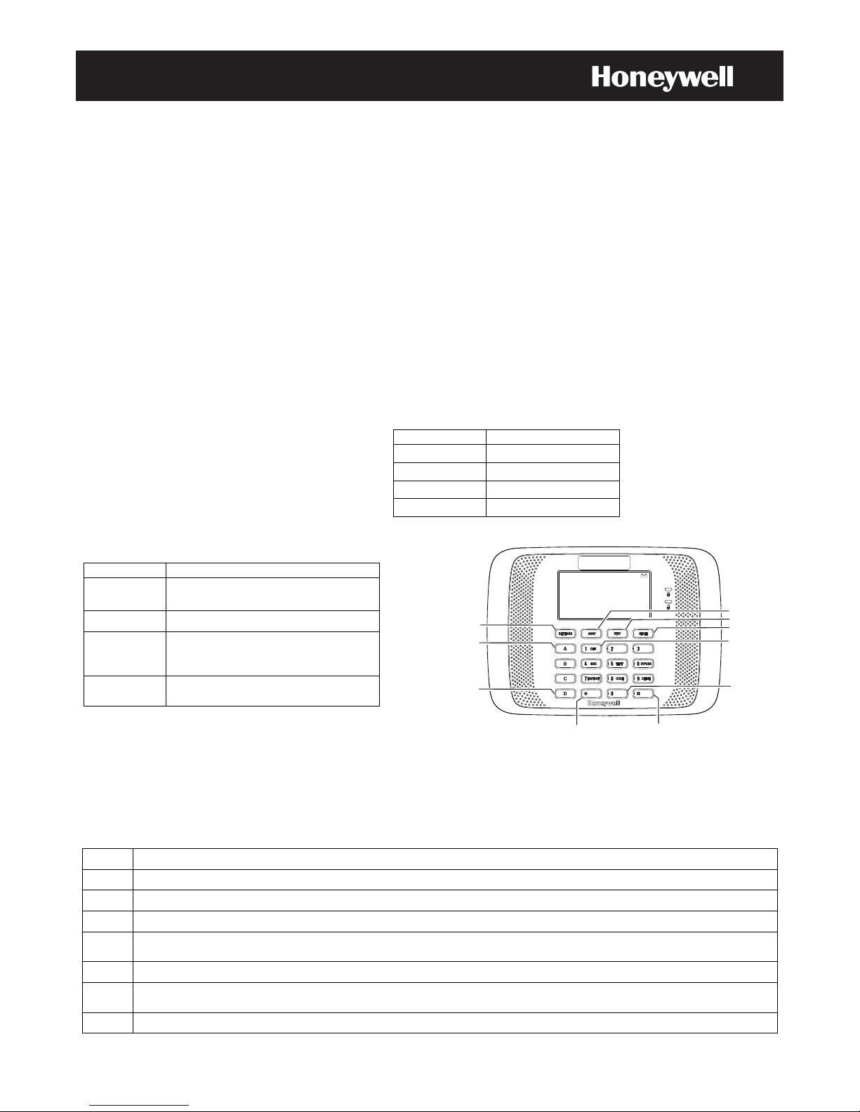
Navigation Keys for Menu Mode Programmin
Key Function
Settings Key
Enter and exit
programming
Night Stay Advance to the next page.
Advance to the next field. If at the
[∗∗∗∗]
last field on a page, it advances to
the next page.
[#]
Goes to the previous field. If at the
first field, goes to the previous page.
Menu mode
.
Menu mode programming is supported by the following
controls having the listed or higher firmware revision levels:
Control Firmware Rev. Level
VISTA-10P 4.16
VISTA-15P 9.16
VISTA-20P 9.16
VISTA-21iP 3.16
SETTINGS KEY
(ENTER MENU MODE
PROGRAMMING)
CLEAR
ENTRY
TOGGLE
ENTRIES
AWAY
STAY
NEXT PAGE
YES
NO
To enter menu mode programming:
1. Enter panel programming mode (installer code + 800).
2. Press and hold the Settings key for 2 seconds
The word “communicating” appears briefly, then the first page of programming options appears.
Programming Menus
Menu mode programming consists of seven (7) pages of menus as follows:
Menu Menu Function
1 Phone Number & Account Number Programming
2 Reporting Options (alarm restore, trouble, bypass, AC loss, low battery, test, RF low battery)
3 System Reports (RF jam, cancel, event log full, exit error, open, close away, close stay)
Timing & Miscellaneous Options (exit/entry delays, alarm sounder timeout, fire alarm sound timeout, installer
4
code, auto-stay enable)
5 Zone Number (prompt to begin zone programming)
Zone Programming (zone type, report enable, partition, input type, serial number, response time, hardwire type,
6
zone descriptor)
7 Quit Menu Mode Programming
NEXT FIELD
PREVIOUS FIELD
6162 Series_Keypad_1
Page 2
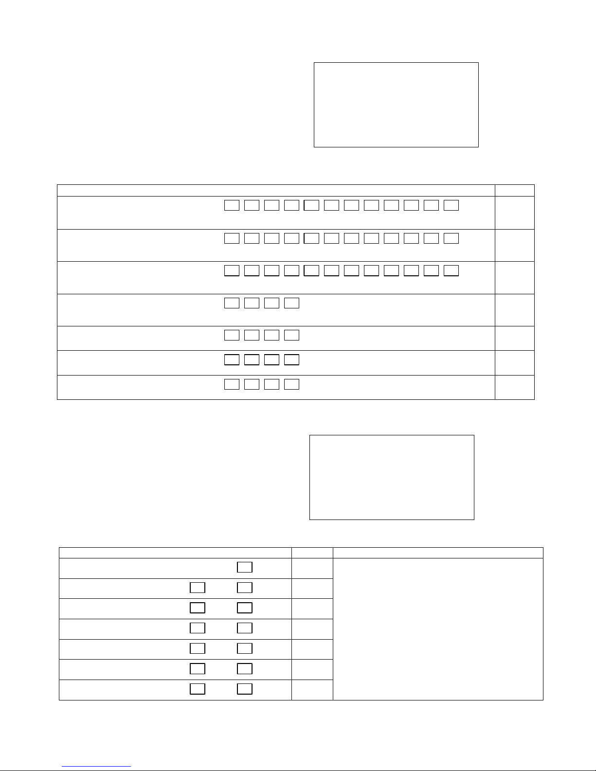
Menu 1: Phone Number & Account Number Programming
NOTES:
Menu mode programming limits the number of digits for
phone numbers and account numbers. If more than the
allowed digits are needed for either a phone number or
account number, use standard control panel
programming mode (installer code + 800) to make those
entries. Refer to the field number column for the
respective programming field in standard programming
mode.
Phone - Account
Primary xxxxxxxxxxxx
Secondary xxxxxxxxxxxx
Download xxxxxxxxxxxx
Pri Acc. P1 FFFF
Pri Acc. P2 FFFF
Sec Acc. P1 FFFF
Sec Acc. P2 FFFF
PHONE NUMBER & ACCOUNT NUMBER PROGRAMMNG
(To clear entries, use the A key.)
Programming Option Entries Field
a. Primary Phone Number
b. Secondary Phone Number
c. Download Phone Number
d. Primary Account Number
Partition 1
e. Primary Account Number
Partition 2
f. Secondary Account Number
Partition 1
g. Secondary Account Number
Partition 2
Enter up to 12 digits, 0-9; B for “∗∗∗∗”; C for “#.”
See Primary phone number for entries.
See Primary phone number for entries.
Enter up to 4 digits; 0-9; B; C; D; AWAY for “E;” STAY for “F.”
See primary account number part. 1 for entries.
See primary account number part. 1 for entries.
See primary account number part. 1 for entries.
Menu 2: Enabling Reporting Options (for ADEMCO Contact ID® reporting only)
NOTES:
This menu lets you enable various reports if ADEMCO
®
Contact ID
format is being used. If another report
format is desired, use standard control panel
programming mode (installer code + 800) to program
these reports. Refer to the field number column for the
respective programming field in standard programming
mode.
REPORTS
Programming Option Event Restore Field Notes
a. Alarm Restore Report
b. Trouble Report
c. Bypass Report
n/a
Reporting: Event Rest
Alarm Rest N
Trouble Y N
Bypass N N
AC Loss Y N
Low Bat Y N
Test N N
RF Low Bat N N
To enable/disable reports:
∗70
0 = No
∗60, ∗71
∗61, ∗72
1 = Yes
To toggle an entry: Use the D key.
∗41
∗42
∗94
∗43
∗45
∗44
∗46
d. AC Loss Report
e. Low Battery Report
f. Test Report
g. RF Low Battery Report
∗62, ∗73
∗63, ∗74
∗64, ∗76
∗67, ∗75
– 2 –
Page 3
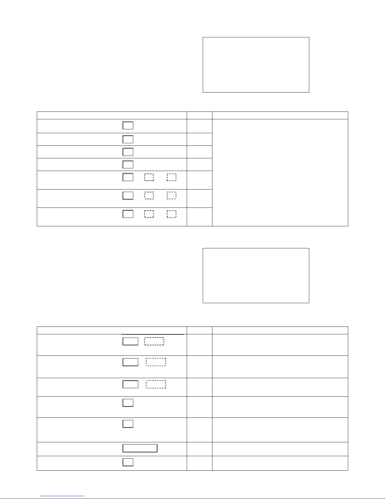
Menu 3: Enabling System Reports (for ADEMCO Contact ID® reporting only)
NOTES:
This menu lets you enable various system reports if
®
ADEMCO Contact ID
format is being used by
selecting yes or no for each report. If another report
format is desired, use standard control panel
programming mode (installer code + 800) to program
these reports. Refer to the field number column for the
respective programming field in standard programming
System Reports
RF Jam N Cancel N
Log Full N
Exit Error N
P1 P2 P3
Open Report N N N
Close Away N N N
Close Stay N N N
mode.
System Reports
Programming Option Event Field Notes
a. RF Jam Report
b. Cancel Report
c. Event Log Full Report
d. Exit Error Report
e. Open Report
f. Close Away Report
(Arm Away)
g. Close Stay Report
(Arm Stay)
Menu 4: Timing and Miscellaneous Options
Part 1 Part 2 Part 3
Part 1 Part 2 Part 3
Part 1 Part 2 Part 3
NOTES:
This menu lets you set entry/exit delays, alarm
sounding timeouts, installer code, and enable the autostay option. To program other options, use standard
control panel programming mode (installer code + 800).
Refer to the field number column for the respective
programming field in standard programming mode.
∗22
∗68
∗89
∗59
∗65
∗66
∗66
To enable/disable a report:
0 = No
1 = Yes
To toggle the entry, use the D key.
Dashed boxes: Indicates the entry is available
only for partitioned systems (ex. VISTA-20P,
VISTA-21iP).
Timing / Misc P1 P2
Exit Delay 60 60
Entry 1 Delay 30 30
Entry 2 Delay 30 30
Alarm Sound Time: 4M
Fire Snd. Timeout N
Installer Code xxxx
Auto Stay: Part 1 & 2
Timing and Miscellaneous Options
Scroll Backward: Use the C key; Scroll Forward: Use the D key.
Dashed boxes: Indicates the entry is available only for partitioned systems (ex. VISTA-20P, VISTA-21iP).
Programming Option Entries Field Notes
a. Exit Delay
b. Entry Delay 1
c. Entry Delay 2
d. Alarm Sounder (Bell)
|
|
Part. 1 Part. 2
|
|
Part. 1 Part. 2
|
|
Part. 1 Part. 2
Timeout
e. Fire Alarm Sound
Timeout
[Fire Snd. Timeout]
f. Installer Code | | |
∗34
∗35
∗36
∗33
∗32
∗20
00 - 96 = 0 - 96 seconds
97 = 120seconds
SIA Controls: Entries less than 45 result in 45-sec. delay.
00 - 96 = 0 - 96 seconds 98 = 180seconds
97 = 120seconds 99 = 240seconds
SIA Controls: Entries less than 30 result in 30-sec. delay.
See Entry Delay 1 for entries.
0 = none 3 = 12 min
1 = 4 min 4 = 16 min
2 = 8 min
0 = Yes - sound stops at timeout set in field ∗33
1 = No - no timeout
4 digits, 0000-9999
g. Auto-Stay
∗84
– 3 –
0 = no 2 = part. 2 only
1 = part. 1 only 3 = part. 1 & part 2
Page 4
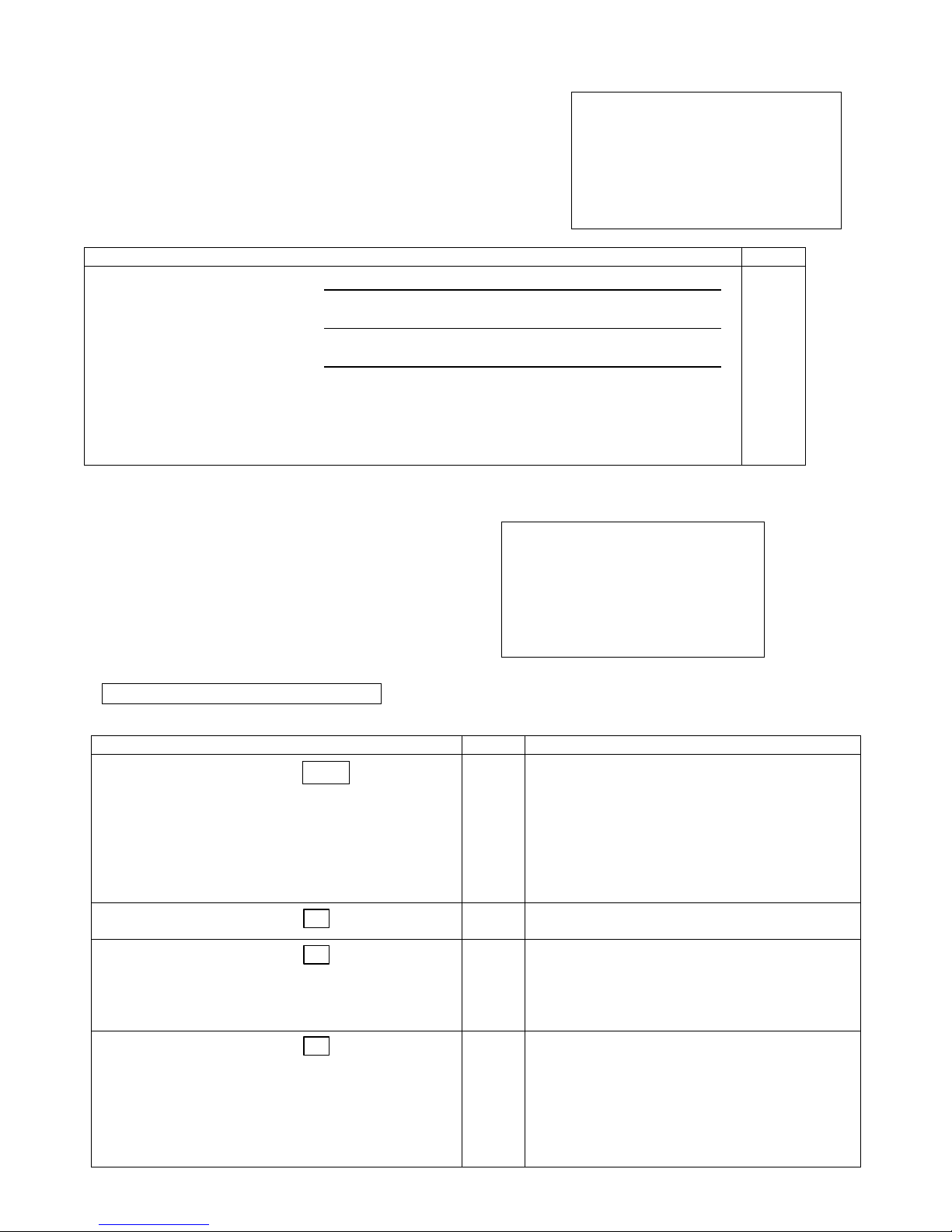
Menu 5: Enter Zone Number
NOTES:
This menu starts Zone Programming, which lets you
program basic zone attributes. Enter the desired zone
number at this prompt, then press [∗]. The Zone
Programming page (menu 6) appears.
When all zones have been programmed, enter 00 to
advance to the Quit menu.
Zone Number
Programming Option Entries Field
a. Zone Number
Menu 6: Zone Programming
NOTES:
Pressing [∗] at the Zone Number prompt displays the
Zone Programming page. To program additional zone
attributes, or to use any other menu mode of
programming, use standard control panel programming
mode (installer code + 800).
DISPLAY NOTE: Typical hardwired zone shown in the
example display. For wireless zones, the Resp / Config line is
replaced by the serial number entry line:
S/N Axxx – xxxx Loop x
Zone Programming
Programming Option Entries Field Notes
a. Zone Type
b. Send Report
c. Partition
d. Input Type
|
Enter Zone No
01
Control Wired Zone RF Zones
Vista-20P and Vista-21iP: 01-08; 09-48
Vista-15P: 01-06; 09-24
Vista-10P: 01-06 09-24
†
Zone Expander Zones;
[∗∗∗∗] = continue programming the selected zone
00 = go to Quit menu
– 4 –
95, 96, 99
95, 96, 99
95, 96, 99
††
RF button zones;
Zone Programming #01
Type: 09 Fire
Send Report: Y Part 1
Input Type: Hardwired
Resp: 350mS Config: EOL
Library 000 000 000
Disp : xxxxxxxxxxxxxxxx
Enter the 2-digit Zone Type from the table below.
00 = Not used 07 = 24-Hr Audible 20 = Arm–STAY*
01 = Entry/exit #1 08 = 24-Hr Aux 21 = Arm–AWAY*
02 = Entry/exit #2 09 = Fire 22 = Disarm*
∗56
03 = Perimeter 10 = Interior w/Delay 23
04 = Int. Follower 12 = Monitor Zone 24 = Silent Burglary
05 = Day/Night 14 = Carbon Monoxide 77 = Keyswitch
06 = 24-Hr Silent 16 = Fire w/Verify 81 = AAV Mon. Zone
To disable the current zone, enter 00.
Press [∗] to advance.
∗56
0 = No – do not send report
1 = Yes – send report
1 = parition 1
2 = partition 2
∗56
3 = partitions 1 & 2
Applies only to partitioned controls.
Press [∗] to advance.
For built-in hardwired zones, the input type
automatically displays “Hardwired.” For wireless
and auxiliary wired zones, select the input type:
∗56
2 = Aux (Aux wired zone; ex. 4219, 4229)
3 = RF. Trans. (supervised RF transmitter)
4 = Unsupv. RF (unsupervised RF transmitter)
5 = RF Button (Unsupervised Button RF)
Press [∗] to advance.
†
09-48; 49-64††
†††
†
09-34; 49-56††
†††
†††
49-56††
†††
Emergency zones
∗56
= No Alarm Resp
Page 5
e. Serial Number
f. Response Time
g. Configuration
(Hardwire Type)
h. Library
(Zone Descriptor)
| | | | | |
Serial Number
Loop
word 1 word 2 word 3
∗56
∗56
∗56
∗82
Manually enter the 7-digit serial number printed on
the label of the transmitter.
Press the [∗] key to move to the “Loop” position,
and then enter the loop number.
To delete an existing serial number, enter 0 in the
loop number field. The serial number will change to
0's. If 0 was entered in error, simply re-enter the
loop number or press [#], the serial number will
return to the display.
Press [∗] to advance.
Applies only to hardwire zones 1-8.
0 = 10mSec
1 = 350mSec
2 = 700mSec
3 = 1.2 seconds
Press [∗] to advance.
Applies only to hardwire zones 1-8.
0 = EOL
1 = NC
2 = NO
3 = zone doubling (ZD) (V20P/V21iP only)
4 = double-balanced (DB) (V20P/V21iP only)
Press [∗] to advance.
For each descriptor word for this zone, enter the
3-digit number from the Vocabulary list.
(see Library list of descriptors on the back page or
in the controls’ Programming Guide)
Press [∗] to return to the Zone Number prompt to
program the next zone or advance to the Quit menu.
Menu 7: Quit Menu Mode Programming
NOTES:
Use this menu to exit Menu mode programming. After
exiting, the “Communicating” message appears
briefly, indicating the control is being updated with the
programmed information.
QUIT QUICK
PROGRAMMING MODE
1 – Exit – Allow Re-entry
2 – Exit – Block Re-entry
3 – Back to 1st Page
Quit Menu
Programming Option Entries Field Notes
a. Exit – Allow Re-Entry
b. Exit – Block Re-Entry
c. Back to 1st Page
1
∗99
2
∗98
3
Exits program mode and allows re-entry by:
Installer Code + 8 0 0, or pressing [∗] and [#] at the
same time within 50 seconds of powering up
Exits programming mode and prevents re-entry by:
Installer Code + 8 0 0.
To reenter programming mode, the system must be
powered down, then powered up. Then press [∗]
and [#] at the same time within 50 seconds of
powering up.
For other ∗98 program mode lockout options, see
field ∗88 in
mode (installer code + 800).
Press 3 to return to the first page of Menu mode
--
programming.
standard control panel programming
– 5 –
Page 6

LIBRARY LIST (Zone Descriptors)
000 (Word Space)
– A –
001 AIR
002 ALARM
004 ALLEY
005 AMBUSH
006 AREA
007 APARTMENT
009 ATTIC
010 AUDIO
– B –
012 BABY
013 BACK
014 BAR
016 BASEMENT
017 BATHROOM
018 BED
019 BEDROOM
020 BELL
021 BLOWER
022 BOILER
023 BOTTOM
025 BREAK
026 BUILDING
– C –
028 CABINET
029 CALL
030 CAMERA
031 CAR
033 CASH
034 CCTV
035 CEILING
036 CELLAR
037 CENTRAL
038 CIRCUIT
040 CLOSED
046 COMPUTER
047 CONTACT
– D –
048 DAUGHTERS
049 DELAYED
050 DEN
051 DESK
052 DETECTOR
053 DINING
054 DISCRIMINATOR
055 DISPLAY
057 DOOR
059 DOWN
060 DOWNSTAIRS
061 DRAWER
062 DRIVEWAY
064 DUCT
∗
∗
∗
∗
∗
∗
∗
∗
∗
∗
∗
∗
– E –
065 EAST
066 ELECTRIC
067 EMERGENCY
068 ENTRY
069 EQUIPMENT
071 EXIT
072 EXTERIOR
– F –
073 FACTORY
075 FAMILY
076 FATHERS
077 FENCE
079 FIRE
080 FLOOR
081 FLOW
082 FOIL
083 FOYER
084 FREEZER
085 FRONT
– G –
089 GARAGE
090 GAS
091 GATE
092 GLASS
093 GUEST
094 GUN
– H –
095 HALL
096 HEAT
098 HOLDUP
099 HOUSE
– I –
100 INFRARED
101 INSIDE
102 INTERIOR
103 INTRUSION
– J –
104 JEWELRY
– K –
105 KITCHEN
∗
∗
∗
∗
∗
∗
∗
∗
∗
– L –
106 LAUNDRY
107 LEFT
∗
108 LEVEL
109 LIBRARY
110 LIGHT
111 LINE
113 LIVING
114 LOADING
115 LOCK
116 LOOP
117 LOW
118 LOWER
– M –
119 MACHINE
121 MAIDS
122 MAIN
123 MASTER
125 MEDICAL
126 MEDICINE
128 MONEY
129 MONITOR
130 MOTHERS
131 MOTION
132 MOTOR
– N –
134 NORTH
135 NURSERY
– O –
136 OFFICE
138 OPEN
139 OPENING
140 OUTSIDE
142 OVERHEAD
– P –
143 PAINTING
144 PANIC
145 PASSIVE
146 PATIO
147 PERIMETER
148 PHONE
150 POINT
151 POLICE
152 POOL
153 POWER
– R –
155 RADIO
∗
156 REAR
157 RECREATION
∗
∗
∗
∗
∗
∗
∗
∗
∗
∗
∗
∗
159 REFRIGERATION
160 RF
161 RIGHT
162 ROOM
163 ROOF
– S –
164 SAFE
165 SCREEN
166 SENSOR
167 SERVICE
168 SHED
169 SHOCK
170 SHOP
171 SHORT
173 SIDE
174 SKYLIGHT
175 SLIDING
176 SMOKE
178 SONS
179 SOUTH
180 SPRINKLER
182 STATION
184 STORE
185 STORAGE
186 STORY
190 SUPERVISED
191 SUPERVISION
192 SWIMMING
193 SWITCH
– T –
194 TAMPER
196 TELCO
197 TELEPHONE
199 TEMPERATURE
200 THERMOSTAT
201 TOOL
202 TRANSMITTER
– U –
205 UP
206 UPPER
207 UPSTAIRS
208 UTILITY
∗
∗
∗
∗
∗
∗
∗
Note: Italicized words followed by an asterisk indicate those words supported by the 6162V/6152V Voice Keypads
– V –
209 VALVE
210 VAULT
212 VOLTAGE
– W –
213 WALL
214 WAREHOUSE
216 WEST
217 WINDOW
219 WING
220 WIRELESS
– X –
222 XMITTER
– Y –
223 YARD
– Z –
224 ZONE (No.)
225 ZONE
226 0
227 1
228 1ST
229 2
230 2ND
231 3
232 3RD
233 4
234 4TH
∗
235 5
236 5TH
∗
237 6
238 6TH
239 7
240 7TH
241 8
242 8TH
243 9
244 9TH
∗
∗
∗
∗
∗
∗
Ê800-14049V1IŠ
800-14049V1 7/13 Rev. A
2 Corporate Center Drive, Suite 100
P.O. Box 9040, Melville, NY 11747
Copyright © 2013 Honeywell International Inc.
www.honeywell.com/security
 Loading...