

Page 1
ADEMCO 4208U Universal V-Plex® Eight Zone Expander
!
1. INSERT BOTTOM TABS FIRST.
2. ENGAGE TOP WITH CLIP.
4219-002-V0
INSTALLATION AND SETUP GUIDE
FEATURES
The ADEMCO 4208U is a V-Plex® eight-zone expander for use
with ADEMCO controls that support V-Plex (polling loop)
devices. Characteristics of this device include:
• Can be optionally powered from the control panel aux.
power supply to reduce the amount of current draw from
the polling loop. NOTE: The 4208U cannot be used with an
external power supply for commercial fire applications.
• Uniquely identifies 8 EOLR supervised zones (all zones use
10k resistors, supplied).
• DIP Switches can be used to set zone numbers or serial
numbers.
• When used in the serial number mode, each serial number
in the selected group can be assigned to any zone number.
• Loops A & B can be programmed for fast (10msec)
response.
• Tamper protected.
1. For all fire (NFPA) and UL Commercial Burglary
installations, the 4208U must be tamper protected or
mounted in a tamper-protected cabinet.
2. Refer to the control panel installation instructions for
U
L
specific programming/installation requirements.
3. All circuits are supervised and power-limited.
4. Use only 14-22 AWG wire.
5. Close contact type initiating devices.
6. All zones are Class B, Style B.
7. Voltage rating all zones: 11VDC max., 1.5mA max.
MOUNTING
1. Power should be disconnected before proceeding.
2.
Be sure to mount the 4208U before making any wiring
connections.
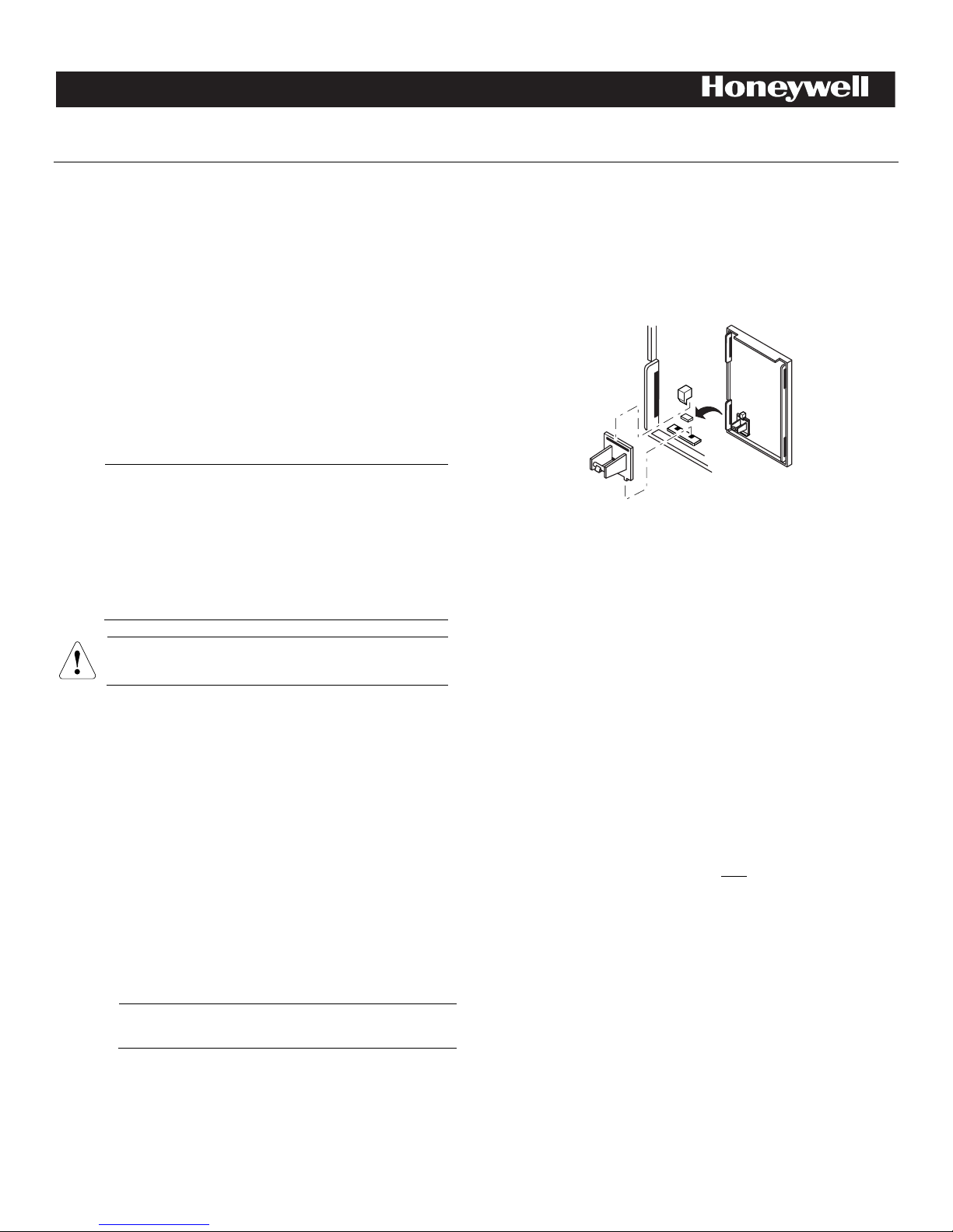
When mounted remotely, tamper protection is required. Holes
on the back of the module’s housing permit it to be mounted
horizontally or vertically. Wires can exit from the side or the
breakout on the back of the housing. To enable tamper
protection, set DIP Switch 8 to OFF and attach the tamper
magnet (provided) (Figure 1) to the module inside cover. Be
sure to enable the expansion zone tamper option at the control
(program field ✼24 = 0). If the module’s cover is removed, the
magnet attached to the cover (positioned near the reed switch)
will cause a tamper signal to be sent to the control for every
active zone on the 4208U module. When the installation is
complete, install the cover and affix the Serial Number and
Zone Assignment Tables to the inside cover of the control.
When mounted inside the cabinet with the control, the 4208U
should be mounted horizontally and does not need tamper
protection, provided the cabinet is supervised. Insert two
screws into the raised metal tabs leaving the heads app. 1/8”
exposed, and then hang the 4208U using the two slots on the
back.
WIRING
For CE installations ADEMCO N6361 EMI suppression
C
Polling loop and protection loop wires can be brought in either
through the back or front of the unit by removing the
knockouts.
bead is required. Refer to the N6361 Installation
E
Instructions for wire routing instructions.
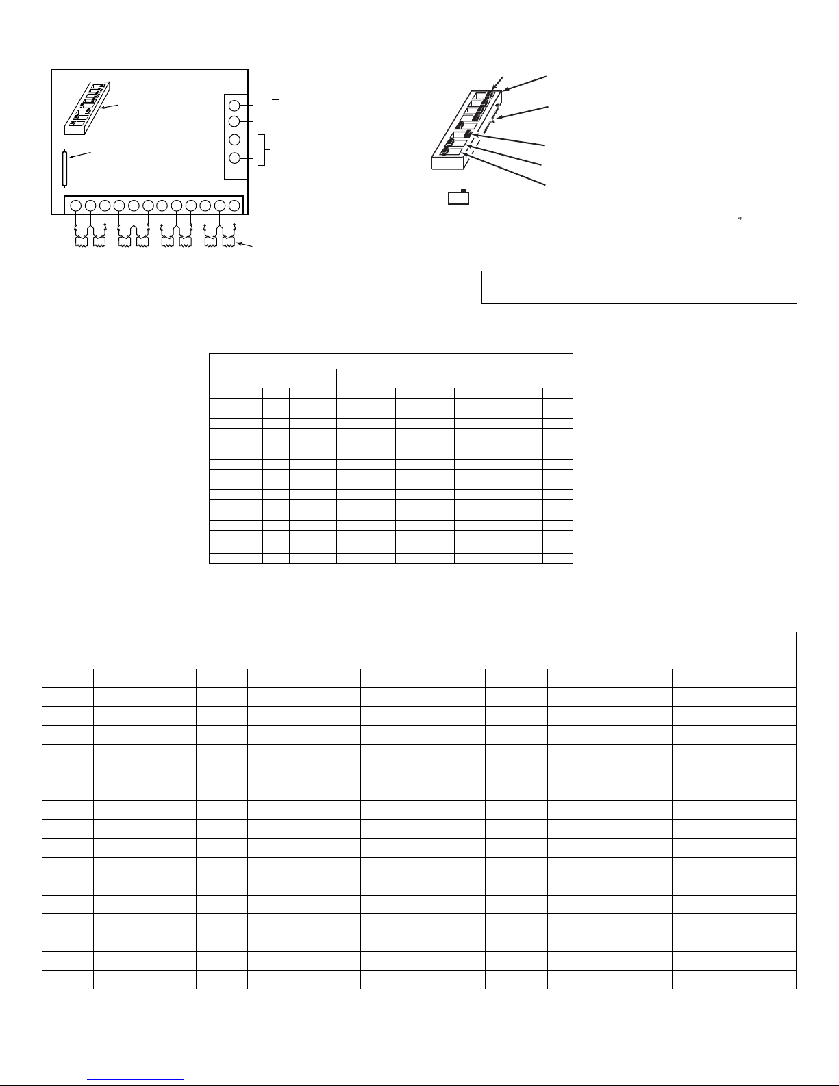
Use 22 gauge twisted pair wire for polling loop connections. All
protection loops use 10k EOL resistors (included). A maximum
resistance of 300 ohms is allowed on protection loops (excluding
EOLR). See Figure 2 for all connections.
Keep in mind that connections to the polling loop are always
required, while power supply connections are optional.
Figure 1. Tamper Magnet Installation
DIP SWITCH SETTINGS
Serial Number Mode:
In the serial number mode, the DIP Switches on the 4208U are
used to assign the unit to a group of 8 serial numbers. You can
assign any serial number to any zone number (except hardwire
zone numbers of the control) and you do not lose zone numbers if
you don’t use all eight loops on the 4208U. Follow steps below
using Table 2 for DIP Switch settings.
Zone Assignment Mode:
In the zone assignment mode, the DIP Switches on the 4208U are
used to assign the unit to a group of 8 consecutive zones. These
zone numbers, once designated for the 4208U, cannot be used for
anything else, even if you don’t use all 8. Follow the steps below
using Table 1 for DIP Switch settings.
Note: Zone Assignment Mode should only be used on panels that
DO NOT support Serial Mode.
Page 2
4208U-SOC-V0
1 2 3 4 5
(EACH LOOP’S MAX
RESISTANCE:
300 ohms + 10k EOLR)
7
8
ON
1
DIP Switches
4208U
TB1
REED (TAMPER) SWITCH
1 98765432
10k 10k 10k 10k 10k 10k 10k 10k
LOOPS: A B C D E F G H
121110
( )
(+)
1
2
3
4
TB2
TO POLLING LOOP
(USE TWISTED PAIR)
( ) GND
(+) 12V
OPTIONAL AUX.
POWER INPUT.
SEE NOTE 1.
NOTES:
IF USING AUXILIARY POWER ON COMMECRICAL
FIRE/BURG COMBINATION SYSTEMS
(e.g. VISTA-128FBP), DO NOT CONNECT THE
POLLING LOOP GROUND ON TERMINAL 2.
AUXILIARY POWER CAN ONLY BE USED IN
BURGLARY APPLICATIONS.
FOR CE INSTALLATIONS A N6363 EMI
SUPPRESSION BEAD IS REQUIRED.
1.
2.
1 2 3 4 5
6
7
ON
ON
OFF
SIDE VIEW
POSITIONS 2-5: SELECT THE 8 SENSOR
DEVICE GROUP ADDRESS
(SHOWN ON, ON, ON,
OFF = 2nd GROUP SELECTION).
POSITION 6:
DEVICE TYPE (SHOWN
ON = “SERIAL NUMBER MODE”).
POSITION 7: NORMALLY SET TO "OFF"
8
ON
1
POSITION 1: SELECT RESPONSE TIME
FOR LOOPS A and B
(SHOWN ON = SLOW).
POSITION 8:
SELECT TAMPER PROTECTION
SETTING (SHOWN
“OFF” = TAMPER ENABLED).
}
Figure 3. DIP Switch Settings
DIP Switch Position
2 3 4 5 6 A B C D E F G H *
On On On On - 1 2 3 4 5 6 7 8 **
On On On - - 9 10 11 12 13 14 15 16
On On - On - 17 18 19 20 21 22 23 24
On On - - - 25 26 27 28 29 30 31 32
On - On On - 33 34 35 36 37 38 39 40
On - On - - 41 42 43 44 45 46 47 48
On - - On - 49 50 51 52 53 54 55 56
On - - - - 57 58 59 60 61 62 63 64
- On On On - 65 66 67 68 69 70 71 72
- On On - - 73 74 75 76 77 78 79 80
- On - On - 81 82 83 84 85 86 87 88
- On - - - 89 90 91 92 93 94 95 96
- - On On - 97 98 99 100 101 102 103 104
- - - On - 113 114 115 116 117 118 119 120 ***
- - - - - 121 122 123 124 125 126 127 N/A
Figure 2. Summary of Connections
Note: For Commercial and Residential Fire installations, no
more than one (1) wire per terminal may be connected.
Table 1. 4208U Zone Assignments
For “Zone Assignment” mode, DIP Switch position 6 must be off.
When using this mode, program each zone’s “Input Type” as “DIP Switch Polling Loop Device” (DP), where applicable.
THIS SWITCH SETTING PRESETS THE LOOPS TO THESE ZONE NUMBERS
(“-” Means “off”)
Loop Designations
Z o n e N um b e r
- - On - - 105 106 107 108 109 110 111 112
**If 9 – 16 is selected for controls that have 9 hardwire zones. Loop A (Zone 9) will be inactive.
*Do not select 1 – 8 for VISTA controls.
***Accommodates option “ONE 4208 IN USE” if referred to in control programming.
NOTE: Consult the Control Panel Instructions to determine the valid zone numbers for that control pan el.
THIS SWITCH SETTING PRESETS THE LOOP TO THESE SERIAL NUMBERS
DIP Switch Position (“-” Means “off”) Loop Designation
2 3 4 5 6 LOOP A LOOP B LOOP C LOOP D LOOP E LOOP F LOOP G LOOP H
ON ON ON ON ON 000-4116 000-4117 000-4118 000-4119 000-4124 000-4125 000-4126 000-4127
ON ON ON - ON 006-9908 006-9909 006-9910 006-9911 006-9916 006-9917 006-9918 006-9919
ON ON - ON ON 013-9812 013-9813 013-9814 013-9815 013-9820 013-9821 013-9822 013-9823
ON ON - - ON 020-9716 020-9717 020-9718 020-9719 020-9724 020-9725 020-9726 020-9727
ON - ON ON ON 027-9620 027-9621 027-9622 027-9623 027-9628 027-9629 027-9630 027-9631
ON - ON - ON 034-9524 034-9525 034-9526 034-9527 034-9532 034-9533 034-9534 034-9535
ON - - ON ON 041-9428 041-9429 041-9430 041-9431 041-9436 041-9437 041-9438 041-9439
ON - - - ON 048-9332 048-9333 048-9334 048-9335 048-9340 048-9341 048-9342 048-9343
- ON ON ON ON 055-9236 055-9237 055-9238 055-9239 055-9244 055-9245 055-9246 055-9247
- ON ON - ON 062-9140 062-9141 062-9142 062-9143 062-9148 062-9149 062-9150 062-9151
- ON - ON ON 069-9044 069-9045 069-9046 069-9047 069-9052 069-9053 069-9054 069-9055
- ON - - ON 076-8948 076-8949 076-8950 076-8951 076-8956 076-8957 076-8958 076-8959
- - ON ON ON 083-8852 083-8853 083-8854 083-8855 083-8860 083-8861 083-8862 083-8863
- - ON - ON 090-8756 090-8757 090-8758 090-8759 090-8764 090-8765 090-8766 090-8767
- - - ON ON 097-8660 097-8661 097-8662 097-8663 097-8668 097-8669 097-8670 097-8671
- - - - ON 104-8564 104-8565 104-8566 104-8567 104-8572 104-8573 104-8574 104-8575
- 2 -
Table 2. 4208U Serial Number Assignments
Page 3

Set the DIP switches on the 4208U as instructed below (see
!
devices are not activated, as they may interfere
Figure 3):
1. Select fast/slow response for loops A and B using DIP
Switch 1: Fast = OFF (10msec) Slow = ON (400msec).
2. Select mode of operation (serial number or zone
assignment mode) using DIP Switch 6: Serial Number
mode = ON; Zone Assignment mode = OFF.
3. Select the group setting using DIP Switches 2, 3, 4, and 5.
See Table 1 for zone assignments or Table 2 for serial
number assignments. If using more than one 4208U, be
sure to set each one to a different group setting.
4. DIP Switch 7: Set DIP Switch 7 to “OFF”.
5. Select the 4208U Tamper Protection setting using DIP
Switch 8: Tamper Disabled = ON Tamper Enabled = OFF.
Tamper will report for every active zone on the 4208U
module.
PROGRAMMING
When setting the 4208U to a group of zone numbers, each zone
must be programmed as follows:
• On ADEMCO 4140XMP and earlier controls, these zones
must be programmed as Left Loop Polling Loop Zones.
• On ADEMCO VISTA-40 and later controls, these zones
must be programmed in the #93 Menu Mode Zone
Programming as INPUT TYPE “7” -- DIP Switch type
polling device (DP).
When setting the 4208U to a group of serial numbers, each zone
must be programmed as INPUT TYPE “6” --SL (Serial Number
Polling Loop Device). Loops can be learned in any order and
assigned to any legitimate zone number.
Table 3. Current Draw Calculations
Power Input Source
(Input Voltage: 8 – 11VDC)
From Polling Loop From Control Panel Aux. Power
Polling Loop Only 28.6mA
Polling Loop and Auxiliary
Power Input
0.6mA 28mA
SPECIFICATIONS
Physical:
Width: 6-7/16”(163mm)
Height: 4-1/4” (108mm)
Depth: 1-1/4” (32mm)
Electrical:
Polling loop input: 8 – 11 VDC
Current draw: 28.6mA max. Aux. Power and Polling loop (see
Table 3)
Power Input (optional): Burg. Applications Only
12VDC @ 28mA (from control panel’s auxiliary power)
NOTE: Do not use a remote power supply.
For UL Listed Commercial Fire Usage:
Use N.O. contacts. Style B, supervise these loops using Model # EOL 100 fire listed
10k EOLRs (purchased separately).
For UL Listed Commercial Burglary Usage:
Use N.O. or N.C. contacts. Supervise using EOLRs supplied.
FEDERAL COMMUNICATIONS COMMISSION STATEMENTS
When prompted to learn the serial number for a particular
zone, you may either enter it manually through the keypad,
through COMPASS Downloader, or “learn” it by momentarily
faulting (shorting) the terminals of that zone as required by the
control. If entering a serial number manually through the
keypad, enter it and press “✼” to advance to the next prompt,
which will ask you for the loop number. Entering a “1” for each
serial number entered.
If learning or entering a serial number, “Duplicate of Zone XX”
Duplicate of Zone XX” is displayed; another device with that
same serial number is already in the system. In that case, use
a different serial number group setting on the 4208U.
If learning a serial number by faulting its
associated loop, make sure that other V-Plex
with the device being learned.
VERIFICATION OF PROGRAMMING
To verify proper programming, the following test should be
performed:
1. Be sure to enable expansion zone tamper protection at the
control (program field ✼24 = 0).
2. Set DIP Switch 8 to OFF (tamper enabled).
3. Replace the 4208U cover and clear the keypad of any
faulted zones.
4. Remove the 4208U’s cover and verify (on the keypad) that
only the zones you designated for this 4208U are indicating
a check (or trouble) condition.
Current Draw
(All zones shorted)
Sensor Loop Response:
Slow: 400 msec (all loops)
Fast: 10 msec (option for loops A and B)
Sensor Loop Current:
(@ Polling loop input = 8 -11VDC, no external power input):
0.52mA (normal)
1.3mA (shorted)
Sensor Loop Max. Resistance:
Up to 300 ohms of wire resistance + 10k EOLR.
Compliance:
NFPA-72 Compliant
- 3 -
Page 4

The user shall not make any changes or modifications to the equipment unless authorized by the Installation Instructions or User's
Manual. Unauthorized changes or modifications could void the user's authority to operate the equipment.
FCC CLASS B STATEMENT
This equipment has been tested to FCC requirements and has been found acceptable for use. The FCC requires the following
statement for your information:
This equipment generates and uses radio frequency energy and if not installed and used properly, that is, in strict accordance with the
manufacturer's instructions, may cause interference to radio and television reception. It has been type tested and found to comply with
the limits for a Class B computing device in accordance with the specifications in Part 15 of FCC Rules, which are designed to provide
reasonable protection against such interference in a residential installation. However, there is no guarantee that interference will not
occur in a particular installation. If this equipment does cause interference to radio or television reception, which can be determined by
turning the equipment off and on, the user is encouraged to try to correct the interference by one or more of the following measures:
• If using an indoor antenna, have a quality outdoor antenna installed.
• Reorient the receiving antenna until interference is reduced or eliminated.
• Move the radio or television receiver away from the receiver/control.
• Move the antenna leads away from any wire runs to the receiver/control.
• Plug the receiver/control into a different outlet so that it and the radio or television receiver are on different branch circuits.
• Consult the dealer or an experienced radio/TV technician for help.
INDUSTRY CANADA CLASS B STATEMENT
This Class B digital apparatus complies with Canadian ICES-003.
Cet appareil numérique de la classe B est conforme à la norme NMB-003 du Canada.
FCC / IC STATEMENT
This device complies with Part 15 of the FCC Rules, and RSS-210 of IC. Operation is subject to the following two conditions: (1) This
device may not cause harmful interference (2) This device must accept any interference received, including interference that may cause
undesired operation.
Cet appareil est conforme à la partie 15 des règles de la FCC & de RSS-210 des Industries Canada. Son fonctionnement est soumis
aux conditions suivantes: (1) Cet appareil ne doit pas causer d’interférences nuisibles. (2) Cet appareil doit accepter toute interférence
reçue y compris les interférences causant une réception indésirable.
SEE THE CONTROL PANEL’S INSTALLATION INSTRUCTIONS FOR COMPLETE INFORMATION REGARDING THE LIMITATIONS OF THE
ENTIRE SECURITY SYSTEM.
For the latest documentation and online support information, please go to:
For the latest warranty information, please go to:
www.honeywell.com/security/hsc/resources/wa.
For patent information, see www.honeywell.com/patents
SUPPORT & WARRANTY
https://mywebtech.honeywell.com/
MyWebTech
Warranty
Patents
ÊN8215V8}Š
N8215V8 2/11 Rev. B
2 Corporate Center Drive, Suite 100
P.O. Box 9040, Melville, NY 11747
Copyright 2009 Honeywell International Inc.
www.security.honeywell.com
 Loading...