

Page 1

™
3800i/3800r
Industrial/Retail/Commercial
Handheld Linear Imager
User’s Guide
Page 2

Disclaimer
Honeywell International Inc. (“HII”) reserves the right to make changes in specifications and other information contained in this document without prior notice,
and the reader should in all cases consult HII to determine whether any such
changes have been made. The information in this publication does not repre
sent a commitment on the part of HII.
HII shall not be liable for technical or editorial errors or omissions contained
herein; nor for incidental or consequential damages resulting from the furnish
ing, performance, or use of this material.
This document contains proprietary information that is protected by copyright.
All rights are reserved. No part of this document may be photocopied, repro
duced, or translated into another language without the prior written consent of
HII.
© 2005-2011 Honeywell International Inc. All rights reserved.
Other product names or marks mentioned in this document may be trademarks
or registered trademarks of other companies and are the property of their
respective owners.
Web Address: www.honeywellaidc.com
-
-
-
Page 3

Product Agency Compliance
USA
FCC Part 15 Subpart B Class B
This device complies with part 15 of the FCC Rules. Operation is subject to
the following two conditions:
1. This device may not cause harmful interference.
2. This device must accept any interference received, including interference
that may cause undesired operation.
This equipment has been tested and found to comply with the limits for a
Class B digital device pursuant to part 15 of the FCC Rules. These limits are
designed to provide reasonable protection against harmful interference in a
residential installation. This equipment generates, uses, and can radiate
radio frequency energy and, if not installed and used in accordance with the
instructions, may cause harmful interference to radio communications.
However, there is no guarantee that interference will not occur in a particular
installation. If this equipment does cause harmful interference to radio or
television reception, which can be determined by turning the equipment off
and on, the user is encouraged to try to correct the interference by one or
more of the following measures:
• Reorient or relocate the receiving antenna.
• Increase the separation between the equipment and receiver.
• Connect the equipment into an outlet on a circuit different from that to
which the receiver is connected.
• Consult the dealer or an experienced radio or television technician for
help.
If necessary, the user should consult the dealer or an experienced radio/
television technician for additional suggestions. The user may find the
following booklet helpful: “Something About Interference.” This is available at
FCC local regional offices. Honeywell is not responsible for any radio or
television interference caused by unauthorized modifications of this
equipment or the substitution or attachment of connecting cables and
equipment other than those specified by Honeywell. The correction is the
responsibility of the user.
Use only shielded data cables with this system.
Caution: Any changes or modifications made to this equipment not
expressly approved by Honeywell may void the FCC authorization
to operate this equipment.
UL Statement
UL listed: UL60950-1.
Page 4

Canada
Industry Canada ICES-003
This Class B digital apparatus complies with Canadian ICES-003. Operation
is subject to the following conditions:
1. This device may not cause harmful interference.
2. This device must accept any interference received, including
interference that may cause undesired operation.
Conformité à la règlementation canadienne
Cet appareil numérique de la Classe B est conforme à la norme NMB-003 du
Canada. Son fonctionnement est assujetti aux conditions suivantes :
1. Cet appareil ne doit pas causer de brouillage préjudiciable.
2. Cet appareil doit pouvoir accepter tout brouillage reçu, y compris le
brouillage pouvant causer un fonctionnement indésirable.
C-UL Statement
C-UL listed: CSA C22.2 No.60950-1-03.
Europe
The CE mark indicates compliance to 2004/108/EC EMC
Directive with Standards EN55022 CLASS B, EN55024,
EN61000-3-2, EN61000-3-3. In addition, complies to 2006/95/EC
Low Voltage Directive, when shipped with recommended power
supply. For further information please contact:
Honeywell Imaging & Mobility Europe BV
Nijverheidsweg 9-13
5627 BT Eindhoven
The Netherlands
Honeywell shall not be liable for use of our product with equipment (i.e.,
power supplies, personal computers, etc.) that is not CE marked and does
not comply with the Low Voltage Directive.
Waste Electrical and Electronic Equipment
Information
Honeywell complies with Directive 2002/96/EC OF THE EUROPEAN
PARLIAMENT AND OF THE COUNCIL of 27 January 2003 on waste
electrical and electronic equipment (WEEE).
This product has required the extraction and use of natural resources for its
production. It may contain hazardous substances that could impact health
and the environment, if not properly disposed.
Page 5

In order to avoid the dissemination of those substances in our environment
and to diminish the pressure on the natural resources, we encourage you to
use the appropriate take-back systems for product disposal. Those systems
will reuse or recycle most of the materials of the product you are disposing in
a sound way.
The crossed out wheeled bin symbol informs you that the product
should not be disposed of along with municipal waste and invites you to use
the appropriate separate take-back systems for product disposal.
If you need more information on the collection, reuse, and recycling systems,
please contact your local or regional waste administration.
You may also contact your supplier for more information on the
environmental performances of this product.
Germany
GS marked to EN60950-1 and EN60825-1.
Australia/NZ
C-Tick Statement
Conforms to AS/NZS 3548.
Mexico
Conforms to NOM-019.
South Korea
This product meets Korean agency approval.
Page 6

International
!
LED Safety Statement
LEDs have been tested and classified as “EXEMPT RISK GROUP” to the
standard: IEC 62471:2006.
Power Source
Use only a Listed Limited Power Source (LPS) or a Class 2 type power supply
compatible with these models.
Patents
For patent information, please refer to www.honeywellaidc.com/patents.
Solids and Water Protection
The 3800i has a rating of IP54, immunity of windblown dust penetration and
splashing water.
The 3800r has a rating of IP41, immunity of foreign particles and dripping water.
Warning
To reduce the possibility of heat-related injuries, avoid touching sections of the scanner that feel warm.
Page 7

Table of Contents
Chapter 1 - Getting Started
3800i/3800r ................................................................. 1-1
About This Manual ...................................................... 1-1
Unpacking the Scanner............................................... 1-1
3800i Models............................................................... 1-2
3800r Models ............................................................. 1-3
3800i/3800r Scanner Identification.............................. 1-4
Connecting the Scanner When Powered by Host
(Keyboard Wedge) ................................................... 1-5
Reading Techniques .................................................. 1-6
Resetting the Standard Product Defaults.................... 1-6
Plug and Play .............................................................. 1-6
Keyboard Wedge Connection ..................................... 1-7
Laptop Direct Connect........................................... 1-7
RS-232 .................................................................. 1-7
Wand Emulation Plug & Play ................................ 1-7
IBM 4683 Ports 5B, 9B, and 17 Interface.............. 1-8
Connecting the Scanner with USB ........................... 1-10
IBM SurePos ....................................................... 1-10
USB PC or Macintosh Keyboard......................... 1-11
USB HID.............................................................. 1-11
USB Com Port Emulation.................................... 1-12
Connecting the Scanner with Serial Wedge ............. 1-13
Chapter 2 - Terminal Interfaces
Terminal ID.................................................................. 2-1
Supported Terminals................................................... 2-2
Keyboard Country ....................................................... 2-4
Keyboard Style............................................................ 2-5
Keyboard Modifiers ..................................................... 2-6
i
Page 8

Connecting the Scanner with RS-232 Serial Port .......2-8
RS-232 Baud Rate................................................. 2-9
RS-232 Word Length: Data Bits, Stop Bits,
and Parity............................................................... 2-9
RS-232 Handshaking........................................... 2-11
Wand Emulation Connection ...............................2-11
Wand Emulation Transmission Rate ...................2-12
Wand Emulation Polarity .....................................2-12
Wand Emulation Idle............................................ 2-12
Wand Emulation ........................................................2-13
Data Block Size ...................................................2-13
Delay Between Blocks .........................................2-13
Overall Checksum ...............................................2-13
Chapter 3 - Output
Good Read Indicators..................................................3-1
Beeper – Good Read............................................. 3-1
Beeper Volume – Good Read................................ 3-1
Beeper Pitch – Good Read.................................... 3-1
Beeper Duration – Good Read ..............................3-2
LED – Good Read .................................................3-2
Number of Beeps – Good Read ............................3-2
Good Read Delay ........................................................ 3-3
User-Specified Good Read Delay.......................... 3-3
Trigger Modes..............................................................3-3
Manual/Serial Trigger ............................................3-3
Automatic Trigger ..................................................3-4
Presentation Mode................................................. 3-5
Hands Free Time-Out..................................................3-5
Reread Delay...............................................................3-5
User-Specified Reread Delay ................................3-6
Aimer Beam Delay (Aimer Beam option only) ............ 3-7
User-Specified Aimer Beam Delay ........................3-7
Aimer Mode (Aimer Beam option only)........................3-7
Aimer Beam Time-Out (Aimer Beam option only) .......3-8
Centering Window .......................................................3-8
ii
Page 9

Output Sequence Overview ...................................... 3-10
Output Sequence Editor...................................... 3-11
Require Output Sequence................................... 3-11
Multiple Symbols ....................................................... 3-13
No Read .................................................................... 3-14
Video Reverse........................................................... 3-14
Chapter 4 - Data Editing
Prefix/Suffix Overview ................................................. 4-1
To Add a Prefix or Suffix:......................................... 4-2
To Clear One or All Prefixes or Suffixes:............... 4-3
To Add a Carriage Return Suffix to all
Symbologies.......................................................... 4-3
Prefix Selections.................................................... 4-3
Suffix Selections.................................................... 4-4
Function Code Transmit........................................ 4-4
Intercharacter, Interfunction, and Intermessage
Delays ......................................................................... 4-4
Intercharacter Delay.............................................. 4-5
User-Specified Intercharacter Delay ..................... 4-5
Interfunction Delay ................................................ 4-6
Intermessage Delay .............................................. 4-6
Chapter 5 - Data Formatting
Data Format Editor Introduction .................................. 5-1
To Add a Data Format........................................... 5-1
Other Programming Selections ............................. 5-2
Data Format Editor Commands............................. 5-2
Data Format Editor................................................ 5-4
Data Formatter ...................................................... 5-5
Alternate Data Formats ......................................... 5-5
Chapter 6 - Secondary Interface
3800i Models............................................................... 6-1
3800r Models .............................................................. 6-1
iii
Page 10

Enabling the Secondary Interface................................6-2
Secondary RS-232 Connection ................................... 6-2
Secondary Code 39 Wand Emulation..........................6-2
Secondary Laser Emulation.........................................6-3
Laser Emulation Transmission Rate............................6-3
Laser Emulation Polarity..............................................6-4
Laser Emulation Idle....................................................6-4
Secondary Trigger Mode ............................................. 6-4
Hands Free Time-Out..................................................6-5
Chapter 7 - Symbologies
Introduction..................................................................7-1
All Symbologies ........................................................... 7-1
Message Length .......................................................... 7-2
Codabar.......................................................................7-2
Codabar Start / Stop Characters............................. 7-3
Codabar Check Character .....................................7-3
Codabar Concatenation......................................... 7-4
Codabar Message Length .....................................7-4
Code 39 ....................................................................... 7-5
Code 39 Start / Stop Characters .............................7-5
Code 39 Check Character .....................................7-6
Code 39 Message Length...................................... 7-6
Code 39 Append.................................................... 7-6
Code 32 Pharmaceutical (PARAF) ........................7-7
Full ASCII............................................................... 7-7
Code 39 Code Page ..............................................7-8
Interleaved 2 of 5.........................................................7-8
Check Digit ............................................................7-8
Interleaved 2 of 5 Message Length .......................7-9
Code 93 ....................................................................... 7-9
Code 93 Message Length.................................... 7-10
Code 93 Code Page ............................................7-10
Straight 2 of 5 Industrial (three-bar start/stop)...........7-11
Straight 2 of 5 Industrial Message Length ...........7-11
iv
Page 11

Straight 2 of 5 IATA (two-bar start/stop).................... 7-11
Straight 2 of 5 IATA Message Length ................. 7-12
Matrix 2 of 5 .............................................................. 7-12
Matrix 2 of 5 Message Length............................. 7-12
Code 11..................................................................... 7-13
Check Digits Required......................................... 7-13
Code 11 Message Length ................................... 7-13
Code 128................................................................... 7-14
ISBT 128 Concatenation ..................................... 7-14
Code 128 Message Length ................................. 7-14
Code 128 Code Page.......................................... 7-15
Code 128 Function Code Transmit ..................... 7-15
Telepen ..................................................................... 7-15
Telepen Output.................................................... 7-16
Telepen Message Length.................................... 7-16
UPC-A ....................................................................... 7-16
UPC-A Check Digit.............................................. 7-17
UPC-A Number System ...................................... 7-17
UPC-A Addenda.................................................. 7-17
UPC-A Addenda Required .................................. 7-18
UPC-A Addenda Separator................................. 7-18
UPC-A/EAN-13 with Extended Coupon Code........... 7-18
UPC-E ....................................................................... 7-19
UPC-E0 and UPC-E1 Expand............................. 7-19
UPC-E0 and UPC-E1 Addenda Required........... 7-19
UPC-E0 and UPC-E1 Addenda Separator.......... 7-20
UPC-E0 Check Digit............................................ 7-20
UPC-E0 Number System .................................... 7-20
UPC-E0 Addenda................................................ 7-21
EAN/JAN 13 .............................................................. 7-21
EAN/JAN 13 Check Digit..................................... 7-21
EAN/JAN 13 Addenda......................................... 7-22
EAN/JAN 13 Addenda Required ......................... 7-22
EAN/JAN 13 Addenda Separator........................ 7-22
ISBN Translate.................................................... 7-23
ISBN.................................................................... 7-23
v
Page 12

EAN/JAN 8.................................................................7-23
EAN/JAN 8 Check Digit .......................................7-23
EAN/JAN 8 Addenda ...........................................7-24
EAN/JAN 8 Addenda Required............................ 7-24
EAN/JAN 8 Addenda Separator ..........................7-24
MSI ............................................................................7-25
MSI Check Character ..........................................7-25
MSI Message Length........................................... 7-25
Plessey Code.............................................................7-26
Plessey Message Length..................................... 7-26
GS1 DataBar Omnidirectional ...................................7-26
GS1 DataBar Limited.................................................7-27
GS1 DataBar Expanded ............................................ 7-27
GS1 DataBar Expanded Message Length........... 7-27
GS1 Emulation...........................................................7-28
China Post ................................................................. 7-28
Korea Post.................................................................7-29
Korea Post Message Length ...............................7-29
PosiCode ................................................................... 7-30
PosiCode Message Length.................................. 7-30
Codablock F...............................................................7-31
Codablock F Message Length .............................7-31
Code 16K...................................................................7-31
Code 16K Message Length .................................7-32
Code 49 ..................................................................... 7-32
Code 49 Message Length.................................... 7-32
Chapter 8 - Interface Keys
Keyboard Function Relationships................................8-1
Supported Interface Keys ........................................... 8-3
Chapter 9 - Utilities
To Add a Test Code I.D. Prefix to All Symbologies ..... 9-1
Show Software Revision..............................................9-1
Show Data Format.......................................................9-1
Resetting the Standard Product Defaults ....................9-1
vi
Page 13

Temporary Visual Xpress Configuration ..................... 9-2
Chapter 10 - Visual Xpress
Visual Xpress Introduction ........................................ 10-1
Installing Visual Xpress from the Web................. 10-2
Chapter 11 - Serial Programming Commands
Conventions .............................................................. 11-1
Menu Command Syntax............................................ 11-1
Query Commands ............................................... 11-2
Concatenation of Multiple Commands ................ 11-2
Responses .......................................................... 11-2
Examples of Query Commands .......................... 11-3
Trigger Commands ................................................... 11-4
Resetting the Standard Product Defaults.................. 11-4
Menu Commands...................................................... 11-5
Chapter 12 - Product Specifications
3800r Product Specifications .................................... 12-1
3800r Depth of Field.................................................. 12-2
3800i Product Specifications .................................... 12-3
3800i Depth of Field .................................................. 12-4
Standard Cable Pinouts ............................................ 12-5
Chapter 13 - Maintenance
Repairs...................................................................... 13-1
Maintenance.............................................................. 13-1
Cleaning the Scanner’s Window ......................... 13-1
Inspecting Cords and Connectors....................... 13-1
Replacing the Interface Cable............................. 13-2
Troubleshooting ........................................................ 13-3
vii
Page 14

Chapter 14 - Customer Support
Technical Assistance.................................................14-1
Online Technical Assistance................................ 14-1
Product Service and Repair.......................................14-2
Online Product Service and Repair Assistance ...14-3
Limited Warranty........................................................14-3
Appendix A - Reference Charts
Symbology Chart .........................................................A-1
ASCII Conversion Chart (Code Page 1252)................A-3
Code Page Mapping of Printed Bar Codes..................A-5
viii
Page 15

1
3800i/3800r
Getting Started
The 3800i and 3800r mark a new performance level for handheld scanners.
Both the 3800i and 3800r are powered by Honeywell Adaptus
nology. The performance of Adaptus technology delivers aggressive read rates
and depths of field on 1D, stacked linear, and matrix codes.
The 3800i handheld industrial image reader is the first industrial class reader to
be powered by Honeywell Adaptus imaging technology. Adaptus technology
allows you to read bar codes at ranges up to 82 inches on paper labels. In addi
tion, this technology allows your 3800i to pick up and process your bar code
image 270 times per second. Although the 3800i uses the same general ergo
nomic design as the 3800r, the 3800i is built to withstand your toughest industrial applications.
Designed for today’s demanding retail and commercial environments, the 3800r
offers a superior reading range, durability, and the ability to read poor quality bar
codes. Linear imaging technology is defined by a bright and sharply focused
aiming line, high resolution imaging, and fast reading speed. The 3800r is com
fortable to hold, easy to use, rugged, and excellent for retail applications, as well
as for all general scanning applications.
TM
Imaging Tech-
About This Manual
This User’s Guide provides installation and programming instructions for the
3800i/3800r. Product specifications, dimensions, warranty, and customer support information are also included.
Honeywell bar code scanners are factory programmed for the most common
terminal and communications settings. If you need to change these settings,
programming is accomplished by scanning the bar codes in this guide.
An asterisk (*) next to an option indicates the default setting.
-
-
-
Unpacking the Scanner
After you open the shipping carton containing the imager, take the following
steps:
• Check to make sure everything you ordered is present.
• Save the shipping container for later storage or shipping.
• Check for damage during shipment. Report damage immediately to the
carrier who delivered the carton.
1 - 1
Page 16

3800i Models
Note: The Honeywell 3800i imager may be used with many interfaces, which
are described in this User’s Guide. Refer to the chart below to determine
the models that can be used with the interface you are using. Refer to
Chapter 6 for programming information regarding Secondary Interfaces.
The chart below lists the 3800i scanner models. “SR” indicates “Standard
Range” linear optics.
Note: Model 3800iSR000E requires 35122063.bin software. Contact Technical
Support to obtain this software (see Technical Assistance on page 14-1).
Models Primary Interfaces
3800iSR00XE TTL Level 232 Laser Emulation
3800iSR03XE True RS-232, True RS-232
serial wedge
3800iSRO5XE Keyboard wedge, TTL level
232, TTL level 232 serial
wedge, IBM 4683, wand emula
tion, USB keyboard, USB HID,
USB retail (IBM SurePOS)
Secondary
Interfaces
Tru e R S- 2 32
Wand Emulation, TTL
level 232
-
1 - 2
Page 17

3800r Models
Note: The Honeywell 3800r scanner may be used with many interfaces, which
are described in this user’s guide. Refer to the chart below to determine
the models that can be used with the interface you are using. Refer to
Chapter 6 for programming information regarding Secondary Interfaces.
The chart below lists the 3800r scanner models. “SR” indicates “Standard
Range” linear optics.
Note: Model 3800rSR000E requires 35122063.bin software. Contact Technical
Support to obtain this software (see Technical Assistance on page 14-1).
Models Primary Interfaces
3800rSR000E TTL Level 232 Laser Emulation
3800rSR030E True RS-232, True RS-232
serial wedge
3800rSR050E Keyboard wedge, TTL level
232, TTL level 232 serial
wedge, IBM 4683, wand emula
tion, USB keyboard, USB HID,
USB retail (IBM SurePOS)
Secondary
Interfaces
Tru e R S- 23 2
Wand Emulation, TTL
level 232
-
1 - 3
Page 18

3800i/3800r Scanner Identification
Compliance
Label location
Item Number,
Serial Number
and Revision
Information
location
1 - 4
Page 19
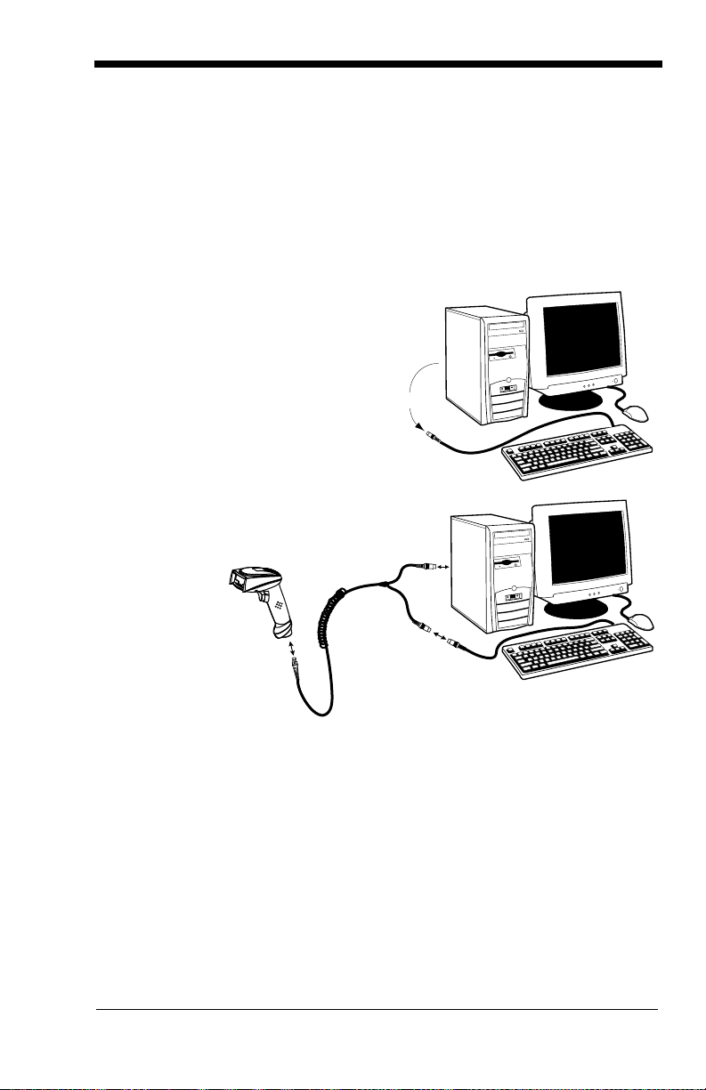
Connecting the Scanner When Powered by Host
Disconnect
1
2
3
(Keyboard
A scanner can be connected between the keyboard and PC as a “keyboard
wedge,” plugged into the serial port, or connected to a portable data terminal in
wand emulation or non decoded output mode. The following is an example of a
keyboard wedge connection:
1. Turn off power to the terminal/computer.
2. Disconnect the keyboard cable
from the back of the terminal/
computer.
3. Connect the
appropriate
interface
cable to the
scanner and
to the
terminal/
computer.
Wedge)
4. Turn the terminal/computer power back on. The scanner beeps.
5. Verify the scanner operation by scanning a bar code from the Sample
Symbols in the back of this manual. The scanner beeps once.
1 - 5
Page 20

Reading Techniques
Good Read
Bad Read
Bad Read
Standard Product Default Settings
The scanner has a view finder that projects a bright red aiming beam that corresponds to its horizontal field of view. The aiming line should be centered horizontally over the bar code; it will not read if the aiming line is in any other
direction.
The best focus point for reading most code densities is about 5 inches (12.7
cm) from the unit. To read single or multiple symbols (on a page or on an
object), hold the imager at an appropriate distance from the target, pull the trig
ger, and center the aiming line on the symbol.
Resetting the Standard Product Defaults
-
If you aren’t sure what programming options are in your scanner, or you’ve
changed some options and want the factory settings restored, scan the
dard Product Default Settings
The Menu Commands starting on page 11-5 lists the factory default settings for
each of the commands (indicated by an asterisk (*) on the programming pages).
bar code below.
Stan-
Plug and Play
Plug and Play bar codes provide instant scanner set up for commonly used
interfaces.
Note: After you scan one of the codes, power cycle the host terminal to have
the interface in effect.
1 - 6
Page 21

Keyboard Wedge Connection
IBM PC AT and Compatibles
with CR suffix
Laptop Direct Connect
with CR suffix
RS-232 Interface
3800r scanners are factory programmed for a keyboard wedge interface to an
IBM PC AT with a USA keyboard. If this is your interface and you do not need to
modify the settings, skip to
If you programmed the scanner for a different terminal interface and you want to
change to an IBM PC AT and compatibles keyboard wedge interface, scan the
bar code below.
Note: The following bar code also programs a carriage return (CR) suffix.
Laptop Direct Connect
For most laptops, scanning the Laptop Direct Connect bar code allows operation of the scanner in parallel with the integral keyboard. The following Laptop
Direct Connect bar code selects terminal ID 03, programs a carriage return
(CR) suffix and turns on Emulate External Keyboard (
RS-232
The RS-232 Interface bar code is used when connecting to the serial port of a
PC or terminal. The following RS-232 Interface bar code also programs a car
riage return (CR) and a line feed (LF) suffix, baud rate, and data format as indicated below. It also changes the trigger mode to manual.
Chapter 3 - Output.
page 2-5).
-
Option Setting
Baud Rate 38400 bps
Data Format 8 data bits, no parity bit, 1 stop bit
Wand Emulation Plug & Play
In Wand Emulation mode, the imager decodes the bar code then sends data in
the same format as a wand imager. The Code 39 Format converts all symbologies to Code 39.
1 - 7
Page 22

The Same Code Format transmits U.P.C., EAN, Code 128 and Interleaved 2 of
Wand Emulation Same Code
Wand Emulation (Code 39 Format)
IBM 4683 Port 5B Interface
IBM 4683 Port 9B HHBCR-1 Interface
IBM 4683 Port 17 Interface
IBM 4683 Port 9B HHBCR-2 Interface
5 without any changes, but converts all other symbologies to Code 39.
The
Wand Emulation Plug & Play Code 39 Format
terminal ID to 61. The
code sets the terminal ID to 64. These Plug & Play bar codes also set the
Transmission Rate to 25 inches per second, Output Polarity to black high, and
Idle State to high. (If you want to change the terminal ID
any other imager settings, please refer to
2-11.)
Wand Emulation Plug & Play Same Code Format
Wand Emulation Connection on page
bar code below sets the
only
, without changing
bar
IBM 4683 Ports 5B, 9B, and 17 Interface
Scan one of the following “Plug and Play” codes to program the imager for IBM
4683 Port 5B, 9B, or 17.
Note: After scanning one of these codes, you must power cycle the cash
register.
Each bar code above also programs the following suffixes for each symbology:
1 - 8
Symbology Suffix
EAN 8 0C
EAN 13 16
UPC-A 0D
Page 23

Symbology Suffix
UPC-E 0A
Code 39 00 0A 0B
Interleaved 2 of 5 00 0D 0B
Code 128 * 00 0A 0B
Code 128 ** 00 18 0B
* Suffixes programmed for Code 128 with IBM 4683 Port 5B, IBM 4683 Port 9B HHBCR1, and IBM 4683 Port 17 Interfaces
**Suffixes programmed for Code 128 with IBM 4683 Port 9 HHBCR-2 Interface
1 - 9
Page 24
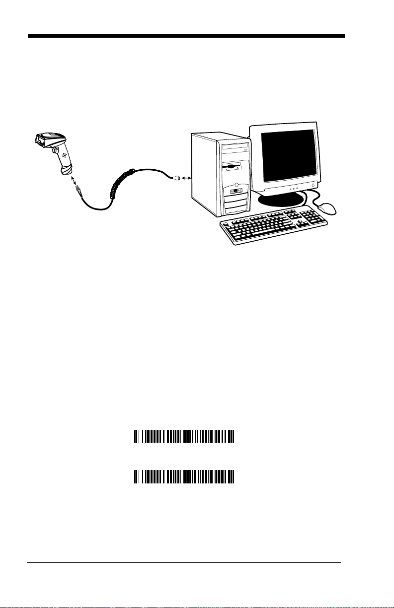
Connecting the Scanner with USB
IBM SurePos (USB Handheld Scanner) Interface
IBM SurePos (USB Tabletop Scanner) Interface
A scanner can be connected to the USB port of a computer.
1. Connect the appropriate interface cable to the scanner and to the computer.
2. The scanner beeps.
3. Verify the scanner operation by scanning a bar code from the Sample
Symbols in the back of this manual.
Note: The following USB “Plug and Play” codes are supported on specific
models. Refer to
applies to your scanner.
For additional USB programming and technical information, refer to the Honeywell “USB Interface Application Note,” available at www.honeywellaidc.com.
3800r Models on page 1-3 to determine if this interface
IBM SurePos
Scan one of the following “Plug and Play” codes to program the imager for IBM
SurePos (USB Handheld scanner) or IBM SurePos (USB Tabletop scanner).
Note: After scanning one of these codes, you must power cycle the cash
register.
1 - 10
Page 25

Each bar code above also programs the following suffixes for each symbology:
USB Keyboard (PC)
USB Keyboard (Mac)
USB Japanese Keyboard (PC)
USB HID Bar Code Scanner
Symbology Suffix
EAN 8 0C
EAN 13 16
UPC-A 0D
UPC-E 0A
Code 39 00 0A 0B
Interleaved 2 of 5 00 0D 0B
Code 128 00 18 0B
USB PC or Macintosh Keyboard
Scan one of the following codes to program the imager for USB PC Keyboard or
USB Macintosh Keyboard. Scanning these codes adds a CR and selects the
terminal ID (USB PC Keyboard - 124, USB Macintosh Keyboard - 125, USB PC
Japanese Keyboard - 134).
USB HID
Scan the following code to program the imager for USB HID bar code scanners.
Scanning this code changes the terminal ID to 131.
1 - 11
Page 26

USB Com Port Emulation
USB Com Port Emulation
On
* Off
On
* Off
Scan the following code to program the imager to emulate a regular RS-232based Com Port. If you are using a Microsoft® Windows® PC, you will need to
download a driver from the Honeywell website
driver will use the next available Com Port number. Apple® Macintosh computers recognize the imager as a USB CDC class device and automatically uses a
class driver. Scanning the code below changes the terminal ID to 130.
Note: No extra configuration (e.g., baud rate) is necessary.
www.honeywell.com/aidc). The
CTS/RTS Emulation
ACK/NAK Mode
1 - 12
Page 27
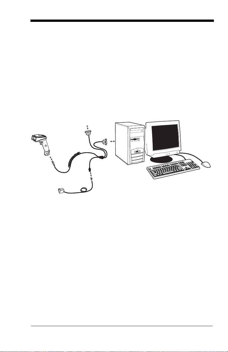
Connecting the Scanner with Serial Wedge
3
4
5
To H o st
6
The imager uses True and TTL signal levels to wedge into an RS-232 serial network. Use only 3800i/3800r serial wedge cables to prevent damage to the
scanner. Refer to
to set the baud rate and communications protocol.
1. Turn off power to the computer.
2. Disconnect the existing serial cable from the computer.
3. Connect the appropriate interface cable to the scanner.
Note: For the scanner to work properly, you must have the correct cable for your
type of computer.
4. Plug the serial connector into the serial port on your computer. Tighten the
two screws to secure the connector to the port.
Connecting the Scanner with RS-232 Serial Port on page 2-8
5. Plug the other serial connector into the host connection and tighten the two
screws.
6. Plug the power pack cable into the receptor on the scanner cable.
7. Plug the power pack into a power source.
8. Once the scanner has been fully connected, power up the computer.
1 - 13
Page 28

To set up the serial wedge terminal ID, use the serial terminal ID 050 and follow
* P1
P2
Both P1 and P2
the instructions on
to transmit. Port 1 corresponds to P1 on the output cable and Port 2 corresponds to P2 on the output cable. Choosing Both sends scanned data to P1
and P2. Default = P1.
page 2-1. Set the port to which you want the scanned data
1 - 14
Page 29

2
Terminal ID
Save
Terminal Interfaces
Terminal ID
If your interface is not a standard PC AT, refer to "Supported Terminals" on
page 2-2 through page 2-3, and locate the Terminal ID number for your PC.
Scan the Terminal ID bar code below, then scan the numeric bar code(s) from
Programming Chart inside the back cover of this manual to program the
the
scanner for your terminal ID. Scan Save to save your selection.
For example, an IBM AT terminal has a Terminal ID of 003. You would scan the
Terminal ID bar code, then 0, 0, 3 from the
cover of this manual, then Save. If you make an error while scanning the digits
(before scanning Save), scan the Discard code on the
scan the Terminal ID bar code, scan the digits, and the Save code again.
Note: After scanning one of these codes, you must power cycle your computer.
Programming Chart inside the back
Programming Chart,
2 - 1
Page 30

Supported Terminals
Terminal Model(s) Terminal ID
DEC VT510, 520, 525 (PC style)
DEC VT510, 520, 525 (DEC style
LK411)
Esprit 200, 400
Heath Zenith PC, AT
HP Vectra
IBM XT
IBM PS/2 25, 30, 77DX2
IBM AT, PS/2 30–286, 50, 55SX, 60,
70, 70–061, 70–121, 80
IBM 102 key 3151, 3161, 3162, 3163, 3191,
3192, 3194, 3196, 3197, 3471,
3472, 3476, 3477
IBM 122 key 3191, 3192, 3471, 3472
IBM 122 key 3196, 3197, 3476, 3477, 3486,
3482, 3488
IBM 122 key 3180
IBM 122 key 3180 data entry keyboard
IBM DOS/V 106 key PC & Workstation
IBM SurePOS USB Handheld Scanner
IBM SurePOS USB Tabletop Scanner
IBM Thinkpad 360 CSE, 340, 750
IBM Thinkpad
IBM Thinkpad 365, 755CV
I/O 122 key 2676D, 2677C, 2677D
ITT 9271
Lee Data IIS
NEC 98XX Series
Olivetti M19, M200
Olivetti M240, M250, M290, M380,
P500
RS-232 True
RS-232 TTL
Serial Wedge
Silicon Graphics Indy, Indigoll
Telex 88 key 078, 078A, 79, 80, 191, 196,
1191,1192, 1471, 1472, 1476,
1477, 1483
Telex 88 key Data Entry Keyboard
Telex 102 key 078, 078A, 79, 80, 191, 196,
1191,1192, 1471, 1472, 1476,
1477, 1483
005
104
005
003
003
001
002
003 *
006
007
008
024
114
102
128***
129***
097
106
003
008
007
007
103
001
003
000**
000
050
005
025
112
045
2 - 2
Page 31

Supported Terminals (Continued)
Terminal Model(s) Terminal ID
Telex 122 key 078, 078A, 79, 80, 191, 196,
USB PC Keyboard
USB Mac Keyboard
USB Com Port
USB HIDPOS
Wand Emulation (Code
39 Format)
Wand Emulation (Same
Code Format)
* Default for 3800i/3800iSR050E models
** Default for 3800rSR030E model (applies to 3800rSR030E models only)
***Applies to 3800i/3800iSR050E model only. It is best to use the Plug and Play bar codes
on
page 1-10 to program these interfaces, rather than scanning the terminal ID listed in this
table.
1191,1192, 1471, 1472, 1476,
1477, 1482, 1483
046
124***
125***
130
131***
061
064
2 - 3
Page 32

Keyboard Country
* United States
Denmark
France
Germany/Austria
Great Britain
Italy
Norway
Spain
Switzerland
Belgium
Finland
Scan the appropriate country code below to program the keyboard for your
country. As a general rule, the following characters are supported, but need
special care for countries other than the United States:
@ | $ # { } [ ] = / ‘ \ < > ~
2 - 4
Page 33

Please refer to Honeywell website (www.honeywellaidc.com) for complete key-
Program Keyboard Country
* Regular
Caps Lock
Shift Lock
Automatic Caps Lock
Autocaps via NumLock
board country support information and applicable interfaces. If you need to program a keyboard for a country other than one listed above, scan the Program
Keyboard Country bar code below, then scan the numeric bar code(s) for the
appropriate country from the inside back cover, then the Save bar code.
Keyboard Style
This programs keyboard styles, such as Caps Lock and Shift Lock.
Regular.
Regular
Caps Lock
Shift Lock
to U.S. keyboards).
Automatic Caps Lock
The software tracks and reflects if you have Caps Lock on or off (AT and PS/2
only). This selection can only be used with systems that have an LED which
notes the Caps Lock status.
Autocaps via NumLock
many, France) where the Caps Lock key cannot be used to toggle Caps Lock.
The NumLock option works similarly to the regular Auotcaps, but uses the Num
Lock key to retrieve the current state of the Caps Lock.
is used when you normally have the Caps Lock key off.
is used when you normally have the Caps Lock key on.
is used when you normally have the Shift Lock key on (not common
is used if you change the Caps Lock key on and off.
bar code should be scanned in countries (e.g., Ger-
Default =
-
2 - 5
Page 34

Emulate External Keyboard
Emulate External Keyboard
Control + ASCII Mode On
* Control + ASCII Mode Off
Turbo Mode On
* Turbo Mode Off
Numeric Keypad Mode On
* Numeric Keypad Mode Off
keyboard (IBM AT or equivalent).
Note: After scanning the Emulate External Keyboard bar code, you must power
cycle your computer.
should be scanned if you do not have an external
Keyboard Modifiers
This modifies special keyboard features, such as CTRL+ ASCII codes and
Turbo Mode.
Control + ASCII Mode On:
control characters for values 00-1F. Windows is the preferred mode. All key
board country codes are supported. DOS mode is a legacy mode, and it does
not support all keyboard country codes. New users should use the Windows
mode. Refer to
Values.
Default = Off
Turbo Mode:
nal drops characters, do not use Turbo Mode.
Numeric Keypad Mode:
numeric keypad.
Keyboard Function Relationships on page 8-1 for CTRL+ ASCII
The scanner sends characters to a terminal faster. If the termi-
Default = Off
The imager sends key combinations for ASCII
-
Default = Off
Sends numeric characters as if entered from a
2 - 6
Page 35

Automatic Direct Connect Mode:
Automatic Direct
Connect Mode On
* Automatic Direct Connect
Mode Off
IBM AT style terminal and the system is dropping characters.
This selection can be used if you have an
Default = Off
2 - 7
Page 36

Connecting the Scanner with RS-232 Serial Port
3
4
5
2
RS-232 Interface
Note: These instructions are for use with the RS-232 power stealer cable.
1. Turn off power to the terminal/computer.
2. Connect the appropriate interface cable to the scanner.
Note: For the scanner to work properly, you must have the correct cable for your
type of terminal/computer.
3. Unplug the mouse or keyboard from the computer. Plug the mouse or
keyboard into the power tap on the scanner cable.
4. Plug the power tap into the mouse or keyboard port.
5. Plug the serial connector into the serial port on your computer. Tighten the
two screws to secure the connector to the port.
6. Once the scanner has been fully connected, power up the computer.
All communication parameters between the scanner and terminal must match
for correct data transfer through the serial port using RS-232 protocol. Scan
ning the RS-232 interface bar code, programs the scanner for an RS-232 interface at 38,400 baud, parity–none, 8 data bits, 1 stop bit, and adds a suffix of a
CR LF.
-
2 - 8
Page 37

RS-232 Baud Rate
300
2400
600
1200
4800
38400
9600
19200
* 115,200
57,600
Baud Rate sends the data from the scanner to the terminal at the specified rate.
The host terminal must be set for the same baud rate as the scanner.
Default = 115,200
.
RS-232 Word Length: Data Bits, Stop Bits, and Parity
Data Bits
tion requires only ASCII Hex characters 0 through 7F decimal (text, digits, and
punctuation), select 7 data bits. For applications which require use of the full
ASCII set, select 8 data bits per character.
Stop Bits
sets the word length at 7 or 8 bits of data per character. If an applica-
sets the stop bits at 1 or 2.
Default = 1.
Default = 8.
2 - 9
Page 38

Parity
7 Data, 1 Stop, Parity Even
7 Data, 1 Stop, Parity None
7 Data, 1 Stop, Parity Odd
7 Data, 2 Stop, Parity Odd
7 Data, 2 Stop, Parity Even
7 Data, 2 Stop Parity None
* 8 Data, 1 Stop, Parity None
8 Data, 1 Stop, Parity Even
8 Data, 1 Stop, Parity Odd
provides a means of checking character bit patterns for validity.
Default = None.
2 - 10
Page 39

RS-232 Handshaking
RTS/CTS On
* XON/OFF Off
* RTS/CTS Off
XON/XOFF On
ACK/NAK On
* ACK/NAK Off
Code 39 Format
Same Code Format
RS-232 handshaking is a set of rules concerning the exchange of data between
serially communicating devices.
Off
NAK
Default = RTS/CTS, XON/XOFF and ACK/
Wand Emulation Connection
The Wand Emulation Connection bar codes should be used if you want to
change the terminal ID
recommend using Wand Emulation Plug & Play bar codes to program your
imager to emulate a wand reader. The Wand Emulation Plug & Play bar codes
change other parameters, in addition to changing the terminal ID. Please refer
Wand Emulation Plug & Play on page 1-7 for further information.
to
In Wand Emulation mode, the imager decodes the bar code then sends data in
the same format as a wand imager. The Code 39 Format converts all symbolo
gies to Code 39.
The Same Code Format transmits U.P.C., EAN, Code 128 and Interleaved 2 of
5 without any changes, but converts all other symbologies to Code 39. 2D sym
bologies are converted to Code 128.
The
Code 39 Format
Code Format
bar code sets the terminal ID to 64.
only
, without changing any other imager settings. We
bar code below sets the terminal ID to 61, and the
Same
-
-
2 - 11
Page 40

Wand Emulation Transmission Rate
10
80
* 25
40
120
150
200
* Black High
White High
* Idle High
Idle Low
The transmission rate is limited by the terminal’s ability to receive data without
dropping characters.
Default = 25 inches/second.
Wand Emulation Polarity
The Polarity can be sent as standard with black bars high, or reversed with
white bars high.
Default = Black High.
Wand Emulation Idle
The idle describes the state of the scanner when no data is being transmitted.
When in Wand Emulation mode, you must set the scanner’s idle state to match
the idle state for the device to which the scanner is connected.
High
2 - 12
.
Default = Idle
Page 41

Wand Emulation
20
80
* 40
60
5ms
500ms
* 50ms
150ms
Note: Changing primary wand emulation settings also changes the secondary
wand emulation settings
page 6-2).
(see Secondary Code 39 Wand Emulation on
Data Block Size
Note: This option is not applicable to Laser Emulation Raw Output (see
Secondary Laser Emulation on page 6-3).
This transmits the data in smaller blocks to prevent buffer overflow.
40.
Default =
Delay Between Blocks
Note: This option is not applicable to Laser Emulation Raw Output (see
Secondary Laser Emulation on page 6-3).
This sets the delay time between data blocks.
Default = 50ms.
Overall Checksum
Note: This option is not applicable to Laser Emulation Raw Output (see
Secondary Laser Emulation on page 6-3).
2 - 13
Page 42

When this option is turned on, a computed check character is added at the end
On
* Off
of the entire message. The check character is the character which when Exclu
sive-OR’d with every preceding character of the message yields a result of 0x00
(00H).
Default = Off.
-
2 - 14
Page 43

3
* On
Off
High
Medium
Off
Low
Low (1600 Hz)
* Medium (3250 Hz)
High (4200 Hz)
Output
Good Read Indicators
Beeper – Good Read
The beeper may be programmed On or Off in response to a good read. Turning
this option off, only turns off the beeper response to a good read indication. All
error and menu beeps are still audible.
Beeper Volume – Good Read
The beeper volume codes modify the volume of the beep the scanner emits on
a good read.
Default = High for the
Default = On.
3800i
, Medium for the
3800r
.
Beeper Pitch – Good Read
The beeper pitch codes modify the pitch (frequency) of the beep the scanner
emits on a good read.
Default = Medium.
3 - 1
Page 44

Beeper Duration – Good Read
* Normal Beep
Short Beep
* On
Off
Number of Pulses
The beeper duration codes modify the length of the beep the scanner emits on
a good read.
Default = Normal.
LED – Good Read
The LED indicator can be programmed On or Off in response to a good read.
Default = On.
Number of Beeps – Good Read
The number of beeps of a good read can be programmed from 1 - 9. The same
number of beeps will be applied to the beeper and LED in response to a good
read. For example, if you program this option to have five beeps, there will be
five beeps and five LED flashes in response to a good read. The beeps and
LED flashes are in sync with one another. To change the number of beeps,
scan the bar code below and then scan a digit (1-9) bar code and the Save bar
code on the
One.
Programming Chart inside the back cover of this manual.
Default =
3 - 2
Page 45

Good Read Delay
* No Delay
Short Delay (500 ms)
Medium Delay (1000 ms)
Long Delay (1500 ms)
User-Specified Good Read Delay
* Manual/Serial Trigger
This sets the minimum amount of time before the scanner can read another bar
Default = No Delay.
code.
User-Specified Good Read Delay
If you want to set your own length for the good read delay, scan the bar code
below, then set the delay (from 0-30,000 milliseconds) by scanning digits from
the inside back cover, then scanning
Save
.
Trigger M od es
Manual/Serial Trigger
You can activate the scanner either by pressing the trigger, or using a serial trigger command (see Trigger Commands on page 11-4). When in manual trigger
mode, the scanner scans until a bar code is read, or until the trigger is released.
When in serial mode, the scanner scans until a bar code has been read or until
the deactivate command is sent. In serial mode, the scanner can also be set to
turn itself off after a specified time has elapsed (see
lows).
Read Time-Out, which fol-
3 - 3
Page 46

Read Time-Out
Read Time-Out
Manual Trigger, Low Power
Low Power Time-Out
Automatic Trigger
Use this selection to set a time-out (in milliseconds) of the scanner’s trigger
when using serial commands to trigger the scanner. Once the scanner has
timed out, you can activate the scanner either by pressing the trigger or using a
serial trigger command. After scanning the Read Time-Out bar code, set the
time-out duration (from 0-300,000 milliseconds) by scanning digits from the
inside back cover, then scanning Save.
Default = 30,000.
Manual Trigger, Low Power
The scanner powers down until the trigger is pulled. When the trigger is pulled,
the scanner powers up and operates until there is no triggering for the time set
with the Low Power Time-Out bar code below. There is a delay of up to one
second in operation when the scanner is first triggered, but there is no delay
when operating in low power time-out mode.
Note: Manual Trigger, Low Power cannot be used with keyboard wedge
applications.
Low Power Time-Out Timer
Scan the Low Power Time-Out bar code to change the time-out duration (in seconds). Then scan the time-out duration (from 0-300 seconds) from the inside
back cover, and Save.
If there are no trigger pulls during the “low power time-out timer” interval, the
scanner goes in low power mode. Whenever the trigger is enabled, the “low
power time-out timer” is reset.
Default = 120 seconds.
Automatic Trigger
The scanner scans continuously at full power with illumination fully on.
Note: If the Automatic Trigger selection is enabled, the aimer beam option is
disabled.
3 - 4
Page 47

Presentation Mode
Presentation Mode
Hands Free Time-Out
Note: Presentation mode does not work when a scanner is programmed for the
laser emulation interface.
Note: If the Presentation Mode selection is enabled, the aimer beam option is
disabled.
The LEDs are off until a bar code is presented to the scanner. Then the LEDs
turn on automatically to read the code. Presentation Mode uses ambient light to
detect the bar codes. If the light level in the room is not high enough, Presenta
tion Mode will not work properly.
Hands Free Time-Out
The Automatic Trigger and Presentation Modes are referred to as “hands free”
modes. If the imager’s trigger is pulled when using a hands free mode, the
imager changes to manual trigger mode. You can set the time the imager
should remain in manual trigger mode by setting the Hands Free Time-Out.
Once the time-out value is reached, (if there have been no further trigger pulls)
the imager reverts to the original hands free mode.
Scan the
(from 0-300,000 milliseconds) from the inside back cover, and
5,000 ms.
Hands Free Time-Out
bar code, then scan the time-out duration
Save
.
Default =
-
Reread Delay
This sets the time period before the scanner can read the
ond time. Setting a reread delay protects against accidental rereads of the
same bar code. Longer delays are effective in minimizing accidental rereads at
POS (point of sale). Use shorter delays in applications where repetitive bar
code scanning is required.
Default = Medium.
same
bar code a sec-
3 - 5
Page 48

Reread Delay only works when in automatic trigger mode (see page 3-4).
Short (500 ms)
* Medium (750 ms)
Long (1000 ms)
Extra Long (2000 ms)
User-Specified Reread Delay
User-Specified Reread Delay
If you want to set your own length for the reread delay, scan the bar code below,
then set the delay (from 0-30,000 milliseconds) by scanning digits from the
inside back cover, then scanning
Save
.
3 - 6
Page 49

Aimer Beam Delay (Aimer Beam option only)
2 seconds
1 second
* Off (no delay)
Delay Duration
Off
* On
The Aimer Beam Delay allows a delay time for the operator to aim the reader
before the standard illumination and decoding starts. The quickset codes sets
the time between when the trigger is pulled and when the decode starts to
either 1 or 2 seconds. During the delay time, the aiming beam appears, but the
illumination LEDs won’t turn on until the delay time is over.
User-Specified Aimer Beam Delay
If you want to set your own length for the duration of the delay, scan the bar
code below, then set the time-out by scanning digits (0 - 4000 ms) from the
Programming Chart inside the back cover of this manual and then scan Save.
Aimer Mode (Aimer Beam option only)
If you are reading codes in applications that exhibit high ambient light, you can
turn on the aimer beam to assist you in reliably finding and scanning a code.
Off
Select
if you don’t want to use the aimer beam.
3 - 7
Page 50

Aimer Beam Time-Out (Aimer Beam option only)
Time-Out Duration
Left of Centering Window
Right of Centering Window
* Centering Off
Centering On
Aimer Beam Time-Out powers down the aimer beam after a time-out if the trigger is still pulled and there isn’t a valid decode. Scan the bar code below, then
set the time-out by scanning digits (from 0 - 240,000 ms) from the
Programming Chart inside the back cover of this manual and then scan Save.
Default = 0 (no time-out)
Centering Window
Use the centering feature to narrow the scanner’s field of view so the scanner
reads only the bar code you want. When centering is turned on, the scanner
only reads codes that intersect or are contained within the centering window
you set up. At least part of a bar code must be within the window to be decoded
or output by the scanner.
To change the left or right edge of the centering window, scan Centering On,
then scan one of the following bar codes. Then scan the percent you want to
shift the centering window using digits on the inside back cover of this manual.
Scan Save. Default Centering = 40% for Left, 60% for Right.
3 - 8
Page 51

The figure below illustrates the percentage range from 1 to 100%.
20%
30%
90%
80%
40% 60%
70%
10%
0%
100%
20%
30%
90%
80%
40% 60%
70%
10%
0%
100%
Decoded bar code
Example: If you have two bar codes next to one another and the centering
window is set to 40% left edge and 60% right edge, only the bar
code that intersects that window will be decoded.
3 - 9
Page 52

Output Sequence Overview
Require Output Sequence
When turned off, the bar code data will be output to the host as the scanner
decodes it. When turned on, all output data must conform to an edited
sequence or the scanner will not transmit the output data to the host device.
Note: This selection is unavailable when the Multiple Symbols Selection is
turned on.
Output Sequence Editor
This programming selection allows you to program the scanner to output data
(when scanning more than one symbol) in whatever order your application
requires, regardless of the order in which the bar codes are scanned. Reading
Default Sequence
the
shown below. These are the defaults. Be certain you want to delete or clear all
formats before you read the
Note: To make Output Sequence Editor selections, you’ll need to know the
code I.D., code length, and character match(es) your application
requires. Use the Alphanumeric symbols (inside back cover) to read
these options.
Note: You must hold the trigger while reading each bar code in a sequence.
To Add an Output Sequence
1. Scan the
11).
2. Code I.D.
On the Symbology Chart on page A-1, find the symbology to which you want
to apply the output sequence format. Locate the Hex value for that symbology and scan the 2 digit hex value from the Programming Chart (inside back
cover).
3. Length
Specify what length (up to 9999 characters) of data output will be acceptable
for this symbology. Scan the four digit data length from the Programming
Chart. (Note: 50 characters is entered as 0050. 9999 is a universal num
ber, indicating all lengths.) When calculating the length, you must count any
programmed prefixes, suffixes, or formatted characters as part of the length
(unless using 9999).
4. Character Match Sequences
On the ASCII Conversion Chart (Code Page 1252), page A-3, find the Hex
value that represents the character(s) you want to match. Use the Programming Chart to read the alphanumeric combination that represents the ASCII
characters. (99 is the Universal number, indicating all characters.)
5. End Output Sequence Editor
Scan
to save your entries.
Enter Sequence
F F
to enter an Output Sequence for an additional symbology, or
symbol programs the scanner to the Universal values,
Default Sequence
symbol (see Require Output Sequence, page 3-
symbol.
Save
-
3 - 10
Page 53

Other Programming Selections
Enter Sequence
Default Sequence
Required
On/Not Required
* Off
•
Discard
This exits without saving any Output Sequence changes.
Output Sequence Editor
Require Output Sequence
When an output sequence is
edited sequence or the scanner will not transmit the output data to the host
device. When it’s
data to conform to an edited sequence, but if it cannot, the scanner transmits all
output data to the host device as is.
When the output sequence is
scanner decodes it.
On/Not Required
Required
Off
, all output data must conform to an
, the scanner will attempt to get the output
, the bar code data is output to the host as the
Note: This selection is unavailable when the Multiple Symbols Selection is
turned on.
3 - 11
Page 54

Output Sequence Example
A - Code 39
B - Code 128
C - Code 93
In this example, you are scanning Code 93, Code 128, and Code 39 bar codes,
but you want the scanner to output Code 39 1st, Code 128 2nd, and Code 93
3rd, as shown below.
Note: Code 93 must be enabled to use this example.
You would set up the sequence editor with the following command line:
SEQBLK62999941FF6A999942FF69999943FF
The breakdown of the command line is shown below:
SEQBLKsequence editor start command
62 code identifier for Code 39
9999 code length that must match for Code 39, 9999 = all lengths
41 start character match for Code 39, 41h = “A”
FF termination string for first code
6A code identifier for Code 128
9999 code length that must match for Code 128, 9999 = all lengths
42 start character match for Code 128, 42h = “B”
FF termination string for second code
69 code identifier for Code 93
9999 code length that must match for Code 93, 9999 = all lengths
43 start character match for Code 93, 43h = “C”
FF termination string for third code
3 - 12
Page 55

To program the previous example using specific lengths, you would have to
On
* Off
count any programmed prefixes, suffixes, or formatted characters as part of the
length. If you use the example on
specific code lengths, you would use the following command line:
SEQBLK62001141FF6A001242FF69001143FF
The breakdown of the command line is shown below:
SEQBLK sequence editor start command
62 code identifier for Code 39
0011 Code 39 code length (9) plus CR suffix (2) = 11
41 start character match for Code 39, 41h = “A”
FF termination string for first code
6A code identifier for Code 128
0012 Code 128 code length (10) plus CR suffix (2) = 12
42 start character match for Code 128, 42h = “B”
FF termination string for second code
69 code identifier for Code 93
0011 Code 93 code length (9) plus CR suffix (2) = 11
43 start character match for Code 93, 43h = “C”
FF termination string for third code
page 3-12, but assume a <CR> suffix and
Multiple Symbols
Note: This feature does not work when the scanner is in Low Power mode.
When this programming selection is turned On, it allows you to read multiple
symbols with a single pull of the scanner’s trigger. If you press and hold the trigger, aiming the scanner at a series of symbols, it reads unique symbols once,
beeping (if turned on) for each read. The scanner attempts to find and decode
new symbols as long as the trigger is pulled. When this programming selection
is turned
Off
, the scanner will only read the symbol closest to the aiming beam.
3 - 13
Page 56

No Read
On
* Off
On
* Off
With No Read turned On, the scanner sends an “NR” to the host if you pull and
release the trigger without reading a code (e.g., bad bar code). If No Read is
Off
turned
If you want a different notation than “NR,” for example, “Error,” or “Bad Code,”
you can edit the output message using the Data Formatter (page 5-5). The hex
code for the No Read symbol is 9C.
, the “NR” will not be sent to the host.
Video Reverse
Video Reverse is used to allow the scanner to read bar codes that are inverted.
The “Off” bar code below is an example of this type of bar code.
Note: If additional menuing is required, Video Reverse must be disabled to
read the menu bar codes and then re-enabled after menuing is
completed.
3 - 14
Page 57

4
Data Editing
Prefix/Suffix Overview
When a bar code is scanned, additional information is sent to the host computer
along with the bar code data. This group of bar code data and additional,
user-defined data is called a “message string.” The selections in this section
are used to build the user-defined data into the message string.
Prefix and Suffix characters are data characters that can be sent before and
after scanned data. You can specify if they should be sent with all symbologies,
or only with specific symbologies. The following illustration shows the break
down of a message string:
-
Prefix
alpha numeric
characters
Scanned Data
variable length1-11
Suffix
1-11
alpha numeric
characters
Points to Keep In Mind
• It is not necessary to build a message string. The selections in this chapter
are only used if you wish to alter the default settings.
Default suffix = None
• A prefix or suffix may be added or cleared from one symbology or all
symbologies.
• You can add any prefix or suffix from the ASCII Conversion Chart (Code Page
1252) on page A-3, plus Code I.D. and AIM I.D.
• You can string together several entries for several symbologies at one time.
• Enter prefixes and suffixes in the order in which you want them to appear on
the output.
.
Default prefix = None.
4 - 1
Page 58

To Add a Prefix or Suffix:
Step 1. Scan the Add Prefix or Add Suffix symbol (page 4-3).
Step 2. Determine the 2 digit Hex value from the Symbology Chart (included in
Appendix A) for the symbology to which you want to apply the prefix
the
or suffix. For example, for Code 128, Code ID is “j” and Hex ID is “6A”.
Step 3. Scan the 2 hex digits from the Programming Chart inside the back
cover of this manual or scan 9, 9 for all symbologies.
Step 4. Determine the hex value from the ASCII Conversion Chart (Code Page
1252) on page A-3, for the prefix or suffix you wish to enter.
Step 5. Scan the 2 digit hex value from the Programming Chart inside the back
cover of this manual.
Step 6. Repeat Steps 4 and 5 for every prefix or suffix character.
Step 7. To add the Code I.D., scan 5, C, 8, 0.
To add AIM I.D., scan 5, C, 8, 1.
To add a backslash (\), scan 5, C, 5, C.
Note: To add a backslash (\) as in Step 7, you must scan 5C twice – once to
create the leading backslash and then to create the backslash itself.
Step 8. Scan Save to exit and save, or scan Discard to exit without saving.
Repeat Steps 1-6 to add a prefix or suffix for another symbology.
Example: Add a Suffix to a specific symbology
To send a CR (carriage return) Suffix for U.P.C. only:
Step 1. Scan Add Suffix.
Step 2. Determine the 2 digit hex value from the Symbology Chart (included in
Appendix A) for U.P.C.
the
Step 3. Scan 6, 3 from the Programming Chart inside the back cover of this
manual.
Step 4. Determine the hex value from the ASCII Conversion Chart (Code Page
1252) on page A-3, for the CR (carriage return).
Step 5. Scan 0, D from the Programming Chart inside the back cover of this
manual.
Step 6. Scan Save, or scan Discard to exit without saving.
4 - 2
Page 59

To Clear One or All Prefixes or Suffixes:
Add CR Suffix
All Symbologies
Add Prefix
Clear One Prefix
Clear All Prefixes
You can clear a single prefix or suffix, or clear all prefixes/suffixes for a symbology. When you Clear One Prefix (Suffix), the specific character you select is
deleted from the symbology you want. When you Clear All Prefixes (Suffixes),
all the prefixes or suffixes for a symbology are deleted.
Step 1. Scan the Clear One Prefix or Clear One Suffix symbol.
Step 2. Determine the 2 digit Hex value from the Symbology Chart (included in
Appendix A) for the symbology from which you want to clear the
the
prefix or suffix.
Step 3. Scan the 2 digit hex value from the Programming Chart inside the back
cover of this manual or scan 9, 9 for all symbologies.
Your change is automatically saved.
To Add a Carriage Return Suffix to all Symbologies
Scan the following bar code if you wish to add a carriage return suffix to all symbologies at once. This action first clears all current suffixes, then programs a
carriage return suffix for all symbologies.
Prefix Selections
4 - 3
Page 60

Suffix Selections
Add Suffix
Clear One Suffix
Clear All Suffixes
* Enable
Disable
Function Code Transmit
When this selection is enabled and function codes are contained within the
scanned data, the scanner transmits the function code to the terminal. Charts
of these function codes are provided in
page 8-3. When the scanner is in keyboard wedge mode, the scan code is con-
verted to a key code before it is transmitted.
Supported Interface Keys starting on
Default = Enable.
Intercharacter, Interfunction, and Intermessage Delays
Some terminals drop information (characters) if data comes through too quickly.
Intercharacter, interfunction, and intermessage delays slow the transmission of
data, increasing data integrity.
Each delay is composed of a 5 millisecond step. You can program up to 99
steps (of 5 ms each) for a range of 0-495 ms.
4 - 4
Page 61

Intercharacter Delay
1 2345
Intercharacter Delay
Prefix Scanned Data Suffix
Intercharacter Delay
Delay Length
Character to Trigger Delay
An intercharacter delay of up to 495 milliseconds may be placed between the
transmission of each character of scanned data. Scan the Intercharacter
Delay bar code below, then scan the number of milliseconds and the SAVE bar
code using the
Programming Chart inside the back cover of this manual.
To remove this delay, scan the Intercharacter Delay bar code, then set the
number of steps to 0. Scan the SAVE bar code using the
inside the back cover of this manual.
Programming Chart
Note: Intercharacter delays are not supported in USB serial emulation.
User-Specified Intercharacter Delay
An intercharacter delay of up to 495 milliseconds may be placed after the transmission of a particular character of scanned data. Scan the Delay Length bar
code below, then scan the number of milliseconds and the SAVE bar code using
Programming Chart inside the back cover of this manual.
the
Next, scan the Character to Trigger Delay bar code, then the 2-digit hex value
for the ASCII character that will trigger the delay
Page 1252) on page A-3.
To remove this delay, scan the Delay Length bar code, and set the number of
steps to 0. Scan the SAVE bar code using the
back cover of this manual.
ASCII Conversion Chart (Code
Programming Chart inside the
4 - 5
Page 62

Interfunction Delay
Interfunction Delays
Prefix Scanned Data Suffix
1 2345STX HT CR LF
Interfunction Delay
2nd Scan Transmission1st Scan Transmission
Intermessage Delay
Intermessage Delay
An interfunction delay of up to 495 milliseconds may be placed between the
transmission of each segment of the message string. Scan the Interfunction
Delay bar code below, then scan the number of milliseconds and the SAVE bar
code using the
To remove this delay, scan the Interfunction Delay bar code, then set the number of steps to 0. Scan the SAVE bar code using the Programming Chart inside
the back cover of this manual.
Programming Chart inside the back cover of this manual.
Intermessage Delay
An intermessage delay of up to 495 milliseconds may be placed between each
scan transmission. Scan the Intermessage Delay bar code below, then scan
the number of milliseconds and the SAVE bar code using the
Chart inside the back cover of this manual.
Programming
To remove this delay, scan the Intermessage Delay bar code, then set the
number of steps to 0. Scan the SAVE bar code using the Programming Chart
inside the back cover of this manual.
4 - 6
Page 63

5
Data Formatting
Data Format Editor Introduction
You may use the Data Format Editor to change the scanner’s output. For example, you can use the Data Format Editor to insert characters at certain points in
bar code data as it is scanned. The selections in the following pages are used
only if you wish to alter the output.
Normally, when you scan a bar code, it gets outputted automatically; however
when you do a format, you must use a “send” command
on page 5-2) within the format program to output data.
Multiple formats may be programmed into the scanner. They are stacked in the
order in which they are entered. However, the following list presents the order
in which formats are applied:
1. Specific Term ID, Actual Code ID, Actual Length
2. Specific Term ID, Actual Code ID, Universal Length
3. Specific Term ID, Universal Code ID, Actual Length
4. Specific Term ID, Universal Code ID, Universal Length
5. Universal Term ID, Actual Code ID, Actual Length
6. Universal Term ID, Actual Code ID, Universal Length
7. Universal Term ID, Universal Code ID, Actual Length
8. Universal Term ID, Universal Code ID, Universal Length
Default Data Format setting = None.
(see Send Commands
If you have changed data format settings, and wish to clear all formats and
return to the factory defaults, scan the Default Data Format code on
page 5-4.
To Add a Data Format
Step 1. Scan the Enter Data Format symbol (page 5-4).
Step 2. Primary/Alternate Format
Determine if this will be your primary data format, or one of 3 alternate
formats. (Alternate formats allow you “single shot” capability to scan
one bar code using a different data format. After the one bar code has
been read, the scanner reverts to the primary data format. See
5.) If you are programming the primary format, scan 0 using the
Programming Chart inside the back cover of this manual. If you are
programming an alternate format, scan 1, 2, or 3, depending on the
alternate format you are programming.
Step 3. Terminal Type
Refer to the Supported Terminals Chart (page 2-2) and locate the Terminal ID number for your PC. Scan three numeric bar codes on the
page 5-
5 - 1
Page 64

inside back cover to program the scanner for your terminal ID (you must
enter 3 digits). For example, scan 0 0 3 for an AT wedge.
Note: The wildcard for all terminal types is 099.
Step 4. Code I.D.
In the Appendix A, find the symbology to which you want to apply the
data format. Locate the Hex value for that symbology and scan the 2
digit hex value from the
this manual.
Step 5. Length
Specify what length (up to 9999 characters) of data will be acceptable
for this symbology. Scan the four digit data length from the
Programming Chart inside the back cover of this manual. (Note: 50
characters is entered as 0050. 9999 is a universal number, indicating
all lengths.)
Step 6. Editor Commands
Refer to the Format Editor Commands Chart (page 5-2). Scan the
symbols that represent the command you want to enter. 94 alphanumeric characters may be entered for each symbology data format.
Step 7. Scan Save from the Programming Chart inside the back cover of this
manual to save your entries.
Programming Chart inside the back cover of
Other Programming Selections
• Clear One Data Format
This deletes one data format for one symbology. If you are clearing the
primary format, scan 0 from the Programming Chart inside the back cover of
this manual. If you are clearing an alternate format, scan 1, 2, or 3, depending
on the alternate format you are clearing. Scan the Terminal Type (refer to the
Supported Terminals Chart on
Chart on page A-1), and the bar code data length for the specific data format
that you want to delete. All other formats remain unaffected.
• Save from the Programming Chart inside the back cover of this manual
This exits, saving any Data Format changes.
• Discard from the Programming Chart inside the back cover of this manual
This exits without saving any Data Format changes.
page 2-2), Code I.D. (refer to the Symbology
Data Format Editor Commands
Send Commands
F1 Send all characters followed by “xx” key or function code, starting from cur-
rent cursor position.
ASCII code, see
F2 Send “nn” characters followed by “xx” key or function code, starting from
current cursor position.
Syntax = F1xx
ASCII Conversion Chart (Code Page 1252) on page A-3.)
Syntax = F2nnxx
(xx stands for the hex value for an
(nn stands for the numeric value
5 - 2
Page 65

(00-99) for the number of characters and xx stands for the hex value for an
ASCII code. See
F3 Send up to but not including “ss” character (Search and Send) starting from
current cursor position, leaving cursor pointing to “ss” character followed by
“xx” key or function code.
hex values for ASCII codes, see ASCII Conversion Chart (Code Page
1252) on page A-3.)
F4 Send “xx” character “nn” times (Insert) leaving cursor in current cursor posi-
tion.
Syntax = F4xxnn
ASCII Conversion Chart (Code Page 1252) on page A-3, and nn is the
numeric value (00-99) for the number of times it should be sent.)
E9 Send all but the last “nn” characters, starting from the current cursor posi-
tion.
Syntax = E9nn
characters that will not be sent at the end of the message.)
ASCII Conversion Chart (Code Page 1252) on page A-3.)
Syntax = F3ssxx
(xx stands for the hex value for an ASCII code, see
(nn is the numeric value (00-99) for the number of
(ss and xx both stand for the
Move Commands
F5 Move the cursor ahead “nn” characters from current cursor position.
Syntax = F5nn
characters the cursor should be moved ahead.)
F6 Move the cursor back “nn” characters from current cursor position.
Syntax = F6nn
characters the cursor should be moved back.)
F7 Move the cursor to the beginning of the data string.
EA Move the cursor to the end of the data string.
(nn stands for the numeric value (00-99) for the number of
(nn stands for the numeric value (00-99) for the number of
Syntax = F7.
Syntax = EA
Search Commands
F8 Search ahead for “xx” character from current cursor position, leaving cursor
pointing to “xx” character.
an ASCII code, see
3.)
F9 Search back for “xx” character from current cursor position, leaving cursor
pointing to “xx” character.
an ASCII code, see
3.)
E6 Search ahead for the first non “xx” character from the current cursor posi-
tion, leaving cursor pointing to non “xx” character.
stands for the hex value for an ASCII code, see
(Code Page 1252) on page A-3.
E7 Search back for the first non “xx” character from the current cursor position,
leaving cursor pointing to non “xx” character.
the hex value for an ASCII code, see ASCII Conversion Chart (Code Page
1252) on page A-3.)
Syntax = F8xx
ASCII Conversion Chart (Code Page 1252) on page A-
Syntax = F9xx
ASCII Conversion Chart (Code Page 1252) on page A-
(xx stands for the hex value for
(xx stands for the hex value for
Syntax = E6xx
ASCII Conversion Chart
Syntax = E7xx
(xx
(xx stands for
Miscellaneous Commands
FB Suppress all occurrences of up to 15 different characters, starting at the
current cursor position, as the cursor is advanced by other commands.
When the FC command is encountered, the suppress function is termi
nated. The cursor is not moved by the FB command. Syntax = FBnnxxyy
. .zz where nn is a count of the number of suppressed characters in the list
5 - 3
-
Page 66

and xxyy .. zz is the list of characters to be suppressed. (xx stands for the
Enter Data Format
* Default Data Format
Clear One Data Format
Save
Discard
Clear All Data Formats
hex value for an ASCII code, see
1252) on page A-3.)
FC Disables suppress filter and clear all suppressed characters.
ASCII Conversion Chart (Code Page
Syntax = FC.
E4 Replaces up to 15 characters in the data string with user-specified charac-
ters. Replacement continues until the E5 command is encountered.
tax = E4nnxx1xx2yy1yy2...zz1zz
characters to be replaced plus replacement characters; xx
where nn is the total count of both
2
defines charac-
1
Syn-
ters to be replaced and xx2 defines replacement characters, continuing
through zz
E5 Terminates character replacement.
and zz2.
1
Syntax = E5.
FE Compare character in current cursor position to the character “xx.” If char-
acters are equal, increment cursor. If characters are not equal, no format
match.
Syntax = FExx
(xx stands for the hex value for an ASCII code, see
ASCII Conversion Chart (Code Page 1252) on page A-3.)
EC Check to make sure there is an ASCII number at the current cursor posi-
tion. If character is not numeric, format is aborted.
Syntax = EC
.
ED Check to make sure there is a non-numeric ASCII character at the current
cursor position. If character is numeric, format is aborted.
Syntax = ED
.
Data Format Editor
5 - 4
Page 67

Data Formatter
Data Formatter Off
* Data Formatter On,
but Not Required
Data Format On, Format Required
Alternate Data Format 1
Alternate Data Format 2
Alternate Data Format 3
When Data Formatter is turned off, the bar code data is output to the host as
read (including prefixes and suffixes). Choose one of the following options.
Default = Data Formatter On.
When Data Formatter is required, all input data must conform to an edited format or the scanner does not transmit the input data to the host device.
Alternate Data Formats
Alternate formats allow you “single shot” capability to scan one bar code using a
different data format than your primary format. When data formats are programmed (see page 5-1), you must input whether you are programming the primary format, or an alternate format numbered 1, 2, or 3.
An alternate format is initiated by scanning one of the 3 alternate format bar
codes below. The scanner will scan the next bar code, formatting the data with
the selected alternate format, then revert immediately to the primary format.
5 - 5
Page 68

5 - 6
Page 69

6
Secondary Interface
By switching secondary interface cables, the 3800i/3800r scanner, for example,
can communicate with a portable data terminal (secondary interface) in addition
to the host terminal (primary interface). See the tables below for the secondary
interfaces for each 3800i/3800r model.
3800i Models
The chart below lists the 3800i scanner models. “SR” indicates “Standard
Range” linear optics.
Note: Model 3800iSR000E requires 35122063.bin software. Contact Technical
Support to obtain this software (see Technical Assistance on page 14-1).
Models Primary Interfaces
3800iSR00XE TTL Level 232 Laser Emulation
3800iSR03XE True RS-232, True RS-232
serial wedge
3800iSRO5XE Keyboard wedge, TTL level
232, TTL level 232 serial
wedge, IBM 4683, wand emula
tion, USB keyboard, USB HID,
USB retail (IBM SurePOS)
Secondary
Interfaces
Tru e R S- 2 32
Wand Emulation, TTL
level 232
-
3800r Models
Note: Model 3800rSR000E requires 35122063.bin software. Contact Technical
Support to obtain this software (see
Models Primary Interfaces
3800rSR000E TTL Level 232 Laser Emulation
3800rSR030E True RS-232, True RS-232
serial wedge
3800rSR050E Keyboard wedge, TTL level
232, TTL level 232 serial
wedge, IBM 4683, wand emula
tion, USB keyboard, USB HID,
USB retail (IBM SurePOS)
Technical Assistance on page 14-1
Secondary
Interfaces
Tru e R S- 2 32
Wand Emulation, TTL
level 232
-
).
6 - 1
Page 70

Enabling the Secondary Interface
* Disable
Enable
RS-232 Interface
Wand Emulation
Code 39 Format
Wand Emulation
Same Code Format
The secondary interface can be programmed at any time.
You can temporarily disable the secondary interface, but still retain the second-
ary interface settings in the imager’s memory by scanning the Disable bar code
below. To re-enable the secondary interface, scan the Enable bar code.
Default =Disable
.
Secondary RS-232 Connection
All communication parameters between the scanner and terminal must match
for correct data transfer through the serial port using RS-232 protocol.
RS-232 programmable selections are used by both the primary and secondary
interfaces. Changing an RS-232 parameter (e.g., baud rate or parity), while in
primary
RS-232 settings, refer to the
section on pages 2-8 to 2-11.
or
secondary mode will affect both interfaces. If you want to change the
Connecting the Scanner with RS-232 Serial Port
Secondary Code 39 Wand Emulation
In Wand Emulation mode, the scanner decodes the bar code then sends data in
the same format as a wand scanner. The Code 39 Format converts all symbol
ogies to Code 39. The Same Code Format transmits U.P.C., EAN, Code 128
and Interleaved 2 of 5 without any changes, but converts all other symbologies
to Code 39. These codes set the transmission rate to 25 inches per second
and the output polarity to black, high.
The
Code 39 Format
Code Format
6 - 2
bar code sets the terminal ID to 64.
bar code below sets the terminal ID to 61, and the
Same
-
Page 71

Secondary Laser Emulation
* Laser Emulation
Same Code Output
Laser Emulation
Raw Output
Laser Emulation
Code 39 Output
* 36
100
Note: Models 3800iSR000E and 3800rSR000E require 35122063.bin software.
Contact Technical Support to obtain this software (see
Assistance on page 14-1).
Use this selection when connecting to a secondary terminal with integral decoding. This also sets the transmission rate to 36 scans per second, the polarity to
white high, and deletes all prefixes and suffixes.
When you scan the following bar code, the imager sends the raw data edges to
the host for host decoding. This also sets the transmission rate to 36 scans per
second and the polarity to white high.
When you scan the following bar code, the scanner decodes and re-encodes
the data and sends the data to the host as Code 39.
Technical
Laser Emulation Transmission Rate
The transmission rate is limited by the terminal’s ability to receive data without
dropping characters.
Default = 36 scans/second.
6 - 3
Page 72

Laser Emulation Polarity
* White High
Black High
Idle Low
* Idle High
* Manual Trigger
Automatic Trigger
Presentation Mode
The Polarity can be sent as standard with white bars high, or reversed with
black bars high.
Default = White High.
Laser Emulation Idle
The idle describes the state of the scanner when no data is being transmitted.
When in Non Decoded mode, you must set the scanner’s idle state to match the
idle state for the device to which the scanner is connected.
Default = Idle High.
Secondary Trigger Mode
Manual Trigger:
ning, idle power is maintained.
You must press the scanner trigger to scan. When not scan-
Default = Manual Trigger
.
Automatic Trigger:
Presentation Mode:
scanner. Then the LEDs turn on automatically to read the code. Presentation
Mode uses ambient light to detect the bar codes.
6 - 4
The scanner scans continuously at full power.
The LEDs are off until a bar code is presented to the
Page 73

Manual Trigger, Low Power:
Manual Trigger, Low Power
Low Power Time-Out
Hands Free Time-Out
below and the scanner “sleeps” until the trigger is pulled. When the trigger is
pulled, the scanner wakes up and operates at normal power until there is no
triggering for the time set with the Low Power Time-Out bar code. Then, the
scanner goes to “sleep” again.
Scan the Manual Trigger, Low Power bar code
Low Power Time-Out:
time-out duration. Then scan the time-out duration (from 0-300 seconds) from
the inside back cover and Save.
Scan the Low Power Time-Out bar code to change the
Default = 120 seconds.
Hands Free Time-Out
The Automatic Trigger and Presentation Modes are referred to as “hands free”
modes. If the imager’s trigger is pulled when using a hands free mode, the
imager changes to manual trigger mode. You can set the time the imager
should remain in manual trigger mode by setting the Hands Free Time-Out.
Once the time-out value is reached, (if there have been no further trigger pulls)
the imager reverts to the original hands free mode.
Note: If you change the time-out duration for the secondary interface, the
duration of the primary interface will also be changed.
Scan the
(from 0-300,000 milliseconds) from the inside back cover, and
5,000 ms.
Hands Free Time-Out
bar code, then scan the time-out duration
Save
.
Default =
6 - 5
Page 74

6 - 6
Page 75

7
All Symbologies On
All Symbologies Off
Symbologies
Introduction
This programming section contains the following menu selections. Refer to
Chapter 11 for settings and defaults.
• All Symbologies • GS1 DataBar Limited
• China Post
• Codabar • Interleaved 2 of 5
• Codablock F • Korea Post
• Code 11 • Matrix 2 of 5
• Code 16K • MSI
• Code 39 • Plessey Code
• Code 32 Pharmaceutical (PARAF) • PosiCode A and B
• Code 49 • Straight 2 of 5 IATA
• Code 93
• Code 128 • Telepen
• EAN/JAN 8 • UPC-A
• EAN/JAN 13
• GS1 DataBar Expanded • UPC-E
• GS1 DataBar
Omnidirectional
• Straight 2 of 5
Industrial
• UPC-A/EAN-13 with
Extended Coupon
Code
All Symbologies
If you want to decode all the symbologies allowable for your scanner, scan the
All Symbologies On
particular symbology, scan All Symbologies Off followed by the On symbol for
that particular symbology.
code. If on the other hand, you want to decode only a
7 - 1
Page 76

Message Length
* On
Off
You are able to set the valid reading length of some of the bar code symbologies.
If the data length of the scanned bar code doesn’t match the valid reading length,
the scanner will issue an error beep. You may wish to set the same value for
minimum and maximum length to force the scanner to read fixed length bar code
data. This helps reduce the chances of a misread.
EXAMPLE: Decode only those bar codes with a count of 9-20 characters.
EXAMPLE: Decode only those bar codes with a count of 15 characters.
For a value other than the minimum and maximum message length defaults,
scan the bar codes included in the explanation of the symbology, then scan the
digit value of the message length and Save bar codes on the
inside the back cover of this manual. The minimum and maximum lengths and
the defaults are included with the respective symbologies.
Min. length = 09 Max. length = 20
Min. length = 15 Max. length = 15
Programming Chart
Codabar
<Default All Codabar Settings>
Codabar
7 - 2
Page 77

Codabar Start / Stop Characters
Transmit
* Don’t Transmit
* No Check Character
Validate Modulo 16 and Transmit
Validate Modulo 16, but
Don’t Transmit
Start/Stop characters identify the leading and trailing ends of the bar code. You
may either transmit, or not transmit Start/Stop characters.
Default = Don’t Transmit
.
Codabar Check Character
Codabar check characters are created using different “modulos.” You can program the scanner to read only Codabar bar codes with Modulo 16 check characters.
Default = No Check Character.
No Check Character
data with or without a check character.
When Check Character is set to
read Codabar bar codes printed with a check character, and will transmit this
character at the end of the scanned data.
When Check Character is set to
read Codabar bar codes printed
check character with the scanned data.
indicates that the scanner reads and transmits bar code
Validate and Transmit
Validate, but Don’t Transmit
with
a check character, but will not transmit the
, the scanner will only
, the unit will only
7 - 3
Page 78

Codabar Concatenation
A12D D34A
Codabar
Character
Stop Start StopStart
On
* Off
Require
Minimum Message Length
Maximum Message Length
Codabar supports symbol concatenation. When you enable concatenation, the
scanner looks for a Codabar symbol having a “D” start character, adjacent to a
symbol having a “D” stop character. In this case the two messages are concat
enated into one with the “D” characters omitted.
Select Require to prevent the scanner from decoding a single “D” Codabar symbol without its companion. This selection has no effect on Codabar symbols
without Stop/Start D characters.
Codabar Message Length
Scan the bar codes below to change the message length. Refer to Message
Length on page 7-2 for additional information. Minimum and Maximum
lengths = 2-60. Minimum Default = 4, Maximum Default = 60.
-
7 - 4
Page 79

Code 39
* On
Off
Transmit
* Don’t Transmit
< Default All Code 39 Settings >
Code 39
Code 39 Start / Stop Characters
Start/Stop characters identify the leading and trailing ends of the bar code. You
may either transmit, or not transmit Start/Stop characters.
Tr an s m it .
Default = Don’t
7 - 5
Page 80

Code 39 Check Character
Validate, but Don’t Transmit
* No Check Character
Validate and Transmit
Minimum Message Length
Maximum Message Length
* Off
On
No Check Character indicates that the scanner reads and transmits bar code
data with or without a check character.
When Check Character is set to Validate, but Don’t Transmit, the unit only
reads Code 39 bar codes printed with a check character, but will not transmit
the check character with the scanned data.
When Check Character is set to Validate and Transmit, the scanner only reads
Code 39 bar codes printed with a check character, and will transmit this charac
ter at the end of the scanned data.
Default = No Check Character.
Code 39 Message Length
Scan the bar codes below to change the message length. Refer to Message
Length on page 7-2 for additional information. Minimum and Maximum
lengths = 0-48. Minimum Default = 0, Maximum Default = 48.
-
Code 39 Append
This function allows the scanner to append the data from several Code 39 bar
codes together before transmitting them to the host computer. When this func
tion is enabled, the scanner stores those Code 39 bar codes that start with a
space (excluding the start and stop symbols), and does not immediately transmit the data. The scanner stores the data in the order in which the bar codes
are read, deleting the first space from each. The scanner transmits the
appended data when it reads a Code 39 bar code that starts with a character
other than a space.
7 - 6
Default = Off.
-
Page 81

Code 32 Pharmaceutical (PARAF)
* Off
On
Full ASCII Off
* Full ASCII On
Code 32 Pharmaceutical is a form of the Code 39 symbology used by Italian
pharmacies. This symbology is also known as PARAF.
Full ASCII
If Full ASCII Code 39 decoding is enabled, certain character pairs within the bar
code symbol will be interpreted as a single character. For example: $V will be
decoded as the ASCII character SYN, and /C will be decoded as the ASCII
character #.
Default = Off
.
NUL %U DLE $P
SOH $A
STX $B
ETX $C
EOT $D
ENQ $E
ACK $F
BEL $G
BS $H
HT $I
LF $J
VT $K
FF $L
CR $M
SO $N
SI $O
DC1 $Q !/A 11AAQQa+Aq+Q
DC2 $R “/B 22 BB RR b+Br+R
DC3 $S #/C 33CCSSc+Cs+S
DC4 $T $/D 44DDTTd+Dt+T
NAK $U %/E 55EE UU e+Eu+U
SYN $V &/F 66FF VV f+Fv+V
ETB $W ‘/G77GGWWg+Gw+W
CAN $X (/H 88HH XX h+Hx+X
EM $Y )/I 99II YYi+Iy+Y
SUB $Z */J :/ZJJZZj+Jz+Z
ESC %A +/K ;%FKK[%Kk+K{%P
FS %B ,/L <%GLL \%Ll+L|%Q
GS %C -- =%HMM]%Mm+M}%R
RS %D .. >%INN^%Nn+N~%S
US %E //O ?%JOO_%Oo+ODEL %T
SP SPACE
00@%VPP‘%Wp+P
Character pairs /M and /N decode as a minus sign and period respectively.
Character pairs /P through /Y decode as 0 through 9.
7 - 7
Page 82

Code 39 Code Page
Code 39 Code Page
* On
Off
Code pages define the mapping of character codes to characters. If the data
received does not display with the proper characters, it may be because the bar
code being scanned was created using a code page that is different from the
one the host program is expecting. If this is the case, scan the bar code below,
select the code page with which the bar codes were created from the chart,
Code Page Mapping of Printed Bar Codes on page A-5, and scan the value and
the SAVE bar code from the Programming Chart inside the back cover of this
manual. The data characters should then appear properly.
Interleaved 2 of 5
< Default All Interleaved 2 of 5 Settings >
Interleaved 2 of 5
Check Digit
No Check Digit indicates that the scanner reads and transmits bar code data
with or without a check digit.
When Check Digit is set to Validate, but Don’t Transmit, the unit only reads
Interleaved 2 of 5 bar codes printed with a check digit, but will not transmit the
check digit with the scanned data.
7 - 8
Page 83

When Check Digit is set to Validate and Transmit, the scanner only reads
Validate, but Don’t Transmit
* No Check Digit
Validate and Transmit
Minimum Message Length
Maximum Message Length
* On
Off
Interleaved 2 of 5 bar codes printed with a check digit, and will transmit this digit
at the end of the scanned data.
Default = No Check Digit.
Interleaved 2 of 5 Message Length
Scan the bar codes below to change the message length. Refer to Message
Length on page 7-2 for additional information. Minimum and Maximum
lengths = 2-80. Minimum Default = 4, Maximum Default = 80.
Code 93
< Default All Code 93 Settings >
Code 93
7 - 9
Page 84

Code 93 Message Length
Minimum Message Length
Maximum Message Length
Code 93 Code Page
Scan the bar codes below to change the message length. Refer to Message
Length on page 7-2 for additional information. Minimum and Maximum
lengths = 0-80. Minimum Default = 0, Maximum Default = 80.
Code 93 Code Page
Code pages define the mapping of character codes to characters. If the data
received does not display with the proper characters, it may be because the bar
code being scanned was created using a code page that is different from the
one the host program is expecting. If this is the case, scan the bar code below,
select the code page with which the bar codes were created from the chart,
Code Page Mapping of Printed Bar Codes on page A-5, and scan the value and
the SAVE bar code from the Programming Chart inside the back cover of this
manual. The data characters should then appear properly.
7 - 10
Page 85

Straight 2 of 5 Industrial (three-bar start/stop)
On
* Off
Minimum Message Length
Maximum Message Length
On
* Off
<Default All Straight 2 of 5 Settings>
Straight 2 of 5 Industrial
Straight 2 of 5 Industrial Message Length
Scan the bar codes below to change the message length. Refer to Message
Length on page 7-2 for additional information. Minimum and Maximum
lengths = 1-48. Minimum Default = 4, Maximum Default = 48.
Straight 2 of 5 IATA (two-bar start/stop)
<Default All Straight 2 of 5 IATA Settings>
Straight 2 of 5 IATA
7 - 11
Page 86

Straight 2 of 5 IATA Message Length
Minimum Message Length
Maximum Message Length
On
* Off
Minimum Message Length
Maximum Message Length
Scan the bar codes below to change the message length. Refer to Message
Length on page 7-2 for additional information. Minimum and Maximum
lengths = 1-48. Minimum Default = 4, Maximum Default = 48.
Matrix 2 of 5
<Default All Matrix 2 of 5 Settings>
Matrix 2 of 5
Matrix 2 of 5 Message Length
Scan the bar codes below to change the message length. Refer to Message
Length on page 7-2 for additional information. Minimum and Maximum
lengths = 1-80. Minimum Default = 4, Maximum Default = 80.
7 - 12
Page 87

Code 11
On
* Off
One Check Digit
* Two Check Digits
Minimum Message Length
Maximum Message Length
<Default All Code 11 Settings>
Code 11
Check Digits Required
This option sets whether 1 or 2 check digits are required with Code 11 bar
codes.
Code 11 Message Length
Scan the bar codes below to change the message length. Refer to Message
Length on page 7-2 for additional information. Minimum and Maximum
lengths = 1-80. Minimum Default = 4, Maximum Default = 80.
Default = Two Check Digits.
7 - 13
Page 88

Code 128
* On
Off
* Off
On
Minimum Message Length
Maximum Message Length
<Default All Code 128 Settings>
Code 128
ISBT 128 Concatenation
In 1994 the International Society of Blood Transfusion (ISBT) ratified a standard
for communicating critical blood information in a uniform manner. The use of
ISBT formats requires a paid license. The ISBT 128 Application Specification
describes 1) the critical data elements for labeling blood products, 2) the current
recommendation to use Code 128 due to its high degree of security and its
space-efficient design, 3) a variation of Code 128 that supports concatenation
of neighboring symbols, and 4) the standard layout for bar codes on a blood
product label. Use the bar codes below to turn concatenation on or off.
=Off.
Default
Code 128 Message Length
Scan the bar codes below to change the message length. Refer to Message
Length on page 7-2 for additional information. Minimum and Maximum
lengths = 0-80. Minimum Default = 0, Maximum Default = 80.
7 - 14
Page 89

Code 128 Code Page
Code 128 Code Page
* Function Codes Off
Function Codes On
On
* Off
Code pages define the mapping of character codes to characters. If the data
received does not display with the proper characters, it may be because the bar
code being scanned was created using a code page that is different from the
one the host program is expecting. If this is the case, scan the bar code below,
select the code page with which the bar codes were created from the chart,
Code Page Mapping of Printed Bar Codes on page A-5, and scan the value and
the SAVE bar code from the Programming Chart inside the back cover of this
manual. The data characters should then appear properly.
Code 128 Function Code Transmit
By default, Code 128 function codes are not transmitted with Code 128 bar
code data. However, if you wish to transmit Code 128 function codes with the
bar code data, scan the Function Codes On bar code, below.
Telepen
<Default All Telepen Settings>
Tel epen
7 - 15
Page 90

Telepen Output
Original Telepen Output
* AIM Telepen Output
Minimum Message Length
Maximum Message Length
* On
Off
Using AIM Telepen Output, the scanner reads symbols with start/stop pattern 1
and decodes them as standard full ASCII (start/stop pattern 1). When Original
Telepen Output is selected, the scanner reads symbols with start/stop pattern 1
and decodes them as compressed numeric with optional full ASCII (start/stop
pattern 2).
Default = AIM Telepen Output.
Telepen Message Length
Scan the bar codes below to change the message length. Refer to Message
Length on page 7-2 for additional information. Minimum and Maximum
lengths = 1-60. Minimum Default = 1, Maximum Default = 60.
UPC-A
<Default All UPC-A Settings>
UPC-A
7 - 16
Page 91

UPC-A Check Digit
* On
Off
Off
* On
* 5 Digit Addenda Off
5 Digit Addenda On
* 2 Digit Addenda Off
2 Digit Addenda On
This selection allows you to specify whether the check digit should be transmitted at the end of the scanned data or not. Default = On.
UPC-A Number System
The numeric system digit of a U.P.C. symbol is normally transmitted at the
beginning of the scanned data, but the unit can be programmed so it will not
transmit it.
Default = On.
UPC-A Addenda
This selection adds 2 or 5 digits to the end of all scanned UPC-A data.
Default = Off for both 2 Digit and 5 Digit Addenda.
7 - 17
Page 92

UPC-A Addenda Required
* Not Required
Required
Off
* On
* On
Off
When Addenda Required is set to on, the scanner will only read UPC-A bar
codes that have addenda.
Default = Not Required.
UPC-A Addenda Separator
When this feature is on, there is a space between the data from the bar code
and the data from the addenda. When turned off, there is no space.
Default = On.
UPC-A/EAN-13 with Extended Coupon Code
Use the following codes to enable or disable UPC-A and EAN-13 with Extended
Coupon Code.
Default = On.
7 - 18
Page 93

UPC-E
UPC-E0 On
* UPC-E0 Off
UPC-E1 On
* UPC-E1 Off
* Off
On
* Not Required
Required
<Default All UPC-E Settings>
UPC-E0 and UPC-E1
Most U.P.C. bar codes lead with the 0 number system. For these codes, use the
UPC-E0 selection. If you need to read codes that lead with the 1 number sys
tem, use the UPC-E1 selection.
Default = Off (UPC-E0) and Off (UPC-E1).
UPC-E0 and UPC-E1 Expand
UPC-E Expand expands the UPC-E code to the 12 digit, UPC-A format.
Default = Off.
-
UPC-E0 and UPC-E1 Addenda Required
When Addenda Required is set to on, the scanner will only read UPC-E bar
codes that have addenda.
Default = Not Required.
7 - 19
Page 94

UPC-E0 and UPC-E1 Addenda Separator
Off
* On
Off
* On
Off
* On
When this feature is on, there is a space between the data from the bar code
and the data from the addenda. When turned off, there is no space.
Default = On.
UPC-E0 Check Digit
Check Digit specifies whether the check digit should be transmitted at the end
of the scanned data or not.
Default = On.
UPC-E0 Number System
The numeric system digit of a U.P.C. symbol is normally transmitted at the
beginning of the scanned data, but the unit can be programmed so it will not
transmit it.
Default = On.
7 - 20
Page 95

UPC-E0 Addenda
* 5 Digit Addenda Off
5 Digit Addenda On
* 2 Digit Addenda Off
2 Digit Addenda On
* On
Off
Off
* On
This selection adds 2 or 5 digits to the end of all scanned UPC-E data.
Default = Off for both 2 Digit and 5 Digit Addenda.
EAN/JAN 13
<Default All EAN/JAN Settings>
EAN/JAN 13
EAN/JAN 13 Check Digit
This selection allows you to specify whether the check digit should be transmitted at the end of the scanned data or not.
Default = On.
7 - 21
Page 96

EAN/JAN 13 Addenda
* 5 Digit Addenda Off
5 Digit Addenda On
* 2 Digit Addenda Off
2 Digit Addenda On
* Not Required
Required
Off
* On
This selection adds 2 or 5 digits to the end of all scanned EAN/JAN 13 data.
Default = Off for both 2 Digit and 5 Digit Addenda.
EAN/JAN 13 Addenda Required
When Addenda Required is set to on, the scanner will only read EAN/JAN 13
bar codes that have addenda.
Default = Not Required.
EAN/JAN 13 Addenda Separator
When this feature is on, there is a space between the data from the bar code
and the data from the addenda. When turned off, there is no space.
Default = On.
Note: If you want to enable or disable EAN13 with Extended Coupon Code,
refer to
7 - 22
UPC-A/EAN-13 with Extended Coupon Code on page 7-18.
Page 97

ISBN Translate
* Off
On
* On
Off
Off
* On
This selection causes EAN-13 Bookland symbols to be translated into their
equivalent ISBN number format.
Default = Off.
ISBN
<Default All EAN/JAN 8 Settings>
EAN/JAN 8
EAN/JAN 8 Check Digit
This selection allows you to specify whether the check digit should be transmitted at the end of the scanned data or not.
Default = On.
7 - 23
Page 98

EAN/JAN 8 Addenda
* 5 Digit Addenda Off
5 Digit Addenda On
* 2 Digit Addenda Off
2 Digit Addenda On
* Not Required
Required
Off
* On
This selection adds 2 or 5 digits to the end of all scanned EAN/JAN 8 data.
Default = Off for both 2 Digit and 5 Digit Addenda.
EAN/JAN 8 Addenda Required
When Addenda Required is set to on, the scanner will only read EAN/JAN 8 bar
codes that have addenda.
Default = Not Required.
EAN/JAN 8 Addenda Separator
When this feature is on, there is a space between the data from the bar code
and the data from the addenda. When turned off, there is no space.
Default = On.
7 - 24
Page 99

MSI
On
* Off
Validate Type 10 and Transmit
* Validate Type 10, but Don’t
Transmit
Minimum Message Length
Maximum Message Length
<Default All MSI Settings>
MSI
MSI Check Character
Different types of check characters are used with MSI bar codes. You can
program the scanner to read MSI bar codes with Type 10 check characters.
Default = Validate Type 10, but Don’t Transmit.
When Check Character is set to
read MSI bar codes printed with the specified type check character, and will
transmit this character at the end of the scanned data.
When Check Character is set to
read MSI bar codes printed with the specified type check character, but will not
transmit the check character with the scanned data.
Validate and Transmit
Validate, but Don’t Transmit
, the scanner will only
, the unit will only
MSI Message Length
Scan the bar codes below to change the message length. Refer to Message
Length on page 7-2 for additional information. Minimum and Maximum
lengths = 4-48. Minimum Default = 4, Maximum Default = 48.
7 - 25
Page 100

Plessey Code
On
* Off
Minimum Message Length
Maximum Message Length
* On
Off
<Default All Plessey Code Settings>
Plessey Code
Plessey Message Length
Scan the bar codes below to change the message length. Refer to Message
Length on page 7-2 for additional information. Minimum and Maximum
lengths = 4-48. Minimum Default = 4, Maximum Default = 48.
GS1 DataBar Omnidirectional
< Default All GS1 DataBar Omnidirectional Settings >
GS1 DataBar Omnidirectional
7 - 26
 Loading...