

Page 1
Honeywell
Copyright © 2000 Honeywell Control Systems
All Rights Reserved
ZA10002-YAD UK07 R01196
ZA10003-YAD UK07 R01196
ZA10004-YAD UK07 R01196
ZA10005-YAD UK07 R01196
ZA10006-YAD UK07 R01196
ZA10053-YAD UK07 R01196
190797-YAD / 190797M-YAD
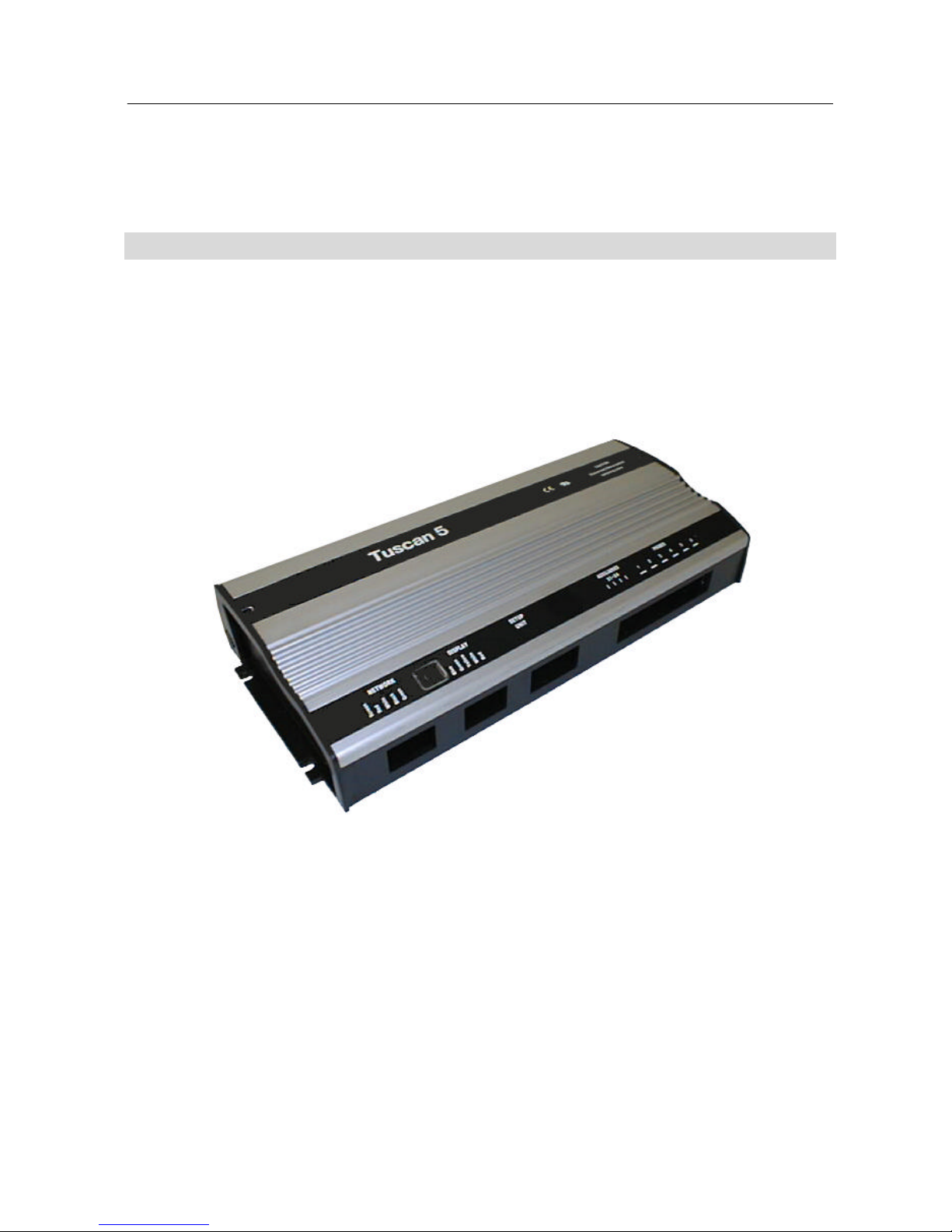
TUSCAN UNIVERSAL CONTROLLER
INSTALLATION GUIDE
Page 2

At the time of writing, this Installation &. Commissioning Guide accurately describes
the product. However, in the course of development of our products we may make
changes without notification.
Honeywell shall not be liable for errors or for incidental or consequential
damages, directly or indirectly, in connection with the furnishing, performance or
misuse of this product or document.
All Installation and Commissioning work on Honeywell equipment should be
carried out by suitably qualified personnel only.
Normal safety precautions and good working practice should be observed, to prevent
damage or injury at all times.
We welcome comments about our products and documentation.
Contact us at :
Honeywell
Cooling & Refrigeration
Newhouse Industrial Estate
Motherwell ML1 5SB
Scotland
U.K.
Tel: +44 (0) 1698 481698
Fax: +44 (0) 1698 481699
www.honeywell.com/cooling
Copyright © Honeywell Control Systems. All rights reserved.
Page 3
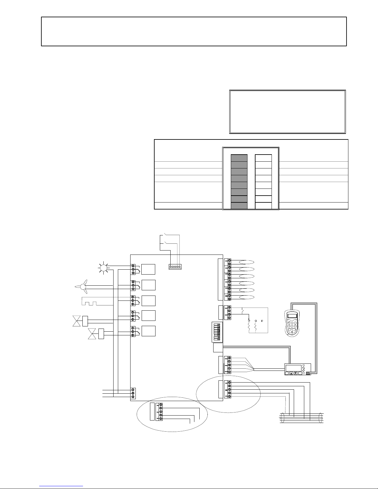
Universal Controller - YAD
Generic
Relay
1
Relay
2
Relay
3
Relay
4
Relay
5
Note: This simplified wiring diagram omits circuit protection
ON
1
2
3
4
5
6
7
8
(P6) Logging
(P5) Honeycomb
(P4) Evaporator out
(P3) Evaporator in
(P2) Air off
(P1) Air on
Temperature Probes -
Bit switches
+
OPTIONS EXECUTE
PAGE
PAGE HOME
SELECT
Setup
Unit
Previous
controller
Next
controller
Genus or alternative
Network cable
-1.5
Ent Esc
Alarm
Network
Defrost
Defrost
Fans
only
Case
off
Normal
white
green
red
Plant fault 2
Plant fault 1
N
L
E
Mains
Supply
DIN Box Display
Fans
Suction line
valve
N/C Liquid line valve
Setup unit extension cable
screen
red
white
black
green
blue
green
yellow
white
red
CN7
CN8
P2
P1
CN9
CN10
CN11
CN12
CN13
CN14
CN15
CN5
CN6
CN4
CN3
CN2
CN1
YAD
Controller on a
Genus Network
screen
white
black
CN7
Controller on a
Woodley Network
Controller
(Fig. 2)
Position of probes should be in accordance
with case manufacturers instructions
10k
5k
Case lights /
blinds
Alarm wired to Relay 5 N/C
contact if bit switch 3 is ON
If gas defrost is
required, connect
N/C S.G.V. to
Relay 3 N/C contact
Defrost Heater
ZA-10002-YAD
Issue a : 5/11/96
Product Part No:
• Universal Controller 190797-YAD
Warning !
Before you work on this equipment, isolate the
electrical supply and also the live feed to any
incoming signals. Remember that live signals
may be derived from more than one source.
Features:
• Controls and monitors HT and LT Generic case
• Genus or alternative network compatible
• Full defrost control
Associated Documents:
∗ Datasheet: ZD 10001-YAD
∗ DIN Box Display: ZF 0920-DIN
∗ Set-up Unit: ZF 0795-DAD
∗ Using Probe Clips: ZG 56003
∗ Health and Safety: ZG 1056
Bit Switch Settings (Fig. 1) : (Shaded area = Switch Position)
Off On
Genus Network 1 Alternative Network
Elm Probes 2 Alternative Probes
Relay 5 switches lights 3 Relay 5 Switches Alarm
Not used....leave off 4 Not used....leave off
5
Generic case option 6
7
LT Range (Frozen Food)
8
HT Range (Fresh Food)
Please Note:
The features and specifications contained in this
Installation Guide may change without notice.
Elm Ltd. shall not be liable for errors or for
incidental or consequential damages in connection
with the furnishing, performance or use of this
product or document.
Page 4
Commissioning:
1. Check all electrical connections (Fig. 2).
2. Make sure that the controller software is
YAD.
3. Check / Set Bit Switches (Fig. 1).
4. Switch the controller ON.
5. Connect Set-up Unit to DIN Box Display
or controller (Fig. 2).
6. Check / Set operating parameters - see
list
7. Save values - if changed
8. Log the controller on to the network then
verify settings on Genus InTouch panel,
Set-up Unit or DIN Box Display.
9. Faults ?..........See ‘Fault Finding’.
Fault Finding:
Set-up Unit does not reach the first
screen.
• If the red LED beside the display
connector is ON or flashing, then the
controller is faulty.
You cannot log the controller on to
the network.
• There may be a controller with the same
name, already logged on the network.
• There may be a maximum 32 controllers
already on the network segment.
• Check on the InTouch panel, P.C. or
Supervisor.
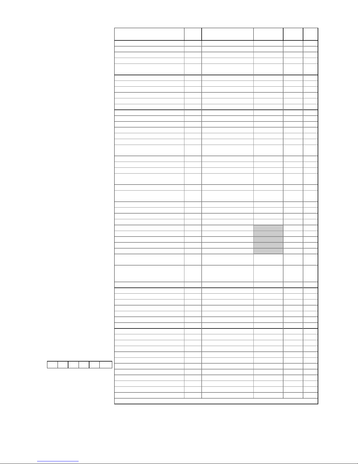
Parameter DIN Range/Units Default
HT(LT)
Dsgn Act.
Cut in Temperature 0 -49 to 30 / °C 0 (-20)
Differential Below 1 0 to 30 / °C 1.5 (2)
Control Weight 2 0 to 100 / % 50
Display Weight 3 0 to 100 / % 50
Log Probe: 0=Off ; 1=Product ;
2=Alarm ; 3=Prod/Alm
8 0 to 3 0
OT Alarm 5 -49 to 60 / °C 5 (-16)
UT Alarm 4 -49 to 60 / °C -2 (-25)
Alarm Delay 6 00:00 to 99:00/Min:Sec 20:00
Defrost Start 11 00:00 to 23:59/Hrs:Mins 01:00
Number of Defrosts per Day 12 0 to 6 6
No Defrost Time 27 0 to 25 / Hrs. 7
Log OT Alarm 10 -49 to 60 / °C 5 (-15)
Log UT Alarm 9 -49 to 60 / °C 0 (-25)
Latch Alarm: 0=Off ; 1=On 7 0 to 1 0
Gas Defrost Detect 13 0 to 30 / °C 18
Defrost Terminate Temperature 14 -49 to 30 / °C 10 (14)
Defrost Minimum Time 15 00:00 to 99:00/Min:Sec 05:00
Defrost Maximum Time 16 00:00 to 99:00/Min:Sec 24:00
(25:00)
Drain Down Time 17 00:00 to 20:00/Min:Sec 01:30
Defrost Min. Recovery Time 18 00:00 to 99:00/Min:Sec 20:00
Defrost Max. Recovery Time 19 00:00 to 99:00/Min:Sec 30:00
Defrost Type: 0=Elect.;1= (2)Gas
2=(3)Gas
22 0 to 2 0
Defrost Alarm Temp. 23 -49 to 60 / °C 20
Defrost Mode: 0=Local ;
1=Remote
24 0 to 1 0
Defrost Hold: 0=Off ; 1=On 26 0 to 1 0
Pulse Defrost: 0=Off ; 1=On 25 0 to 1 0
Pump Down 1 20 00:00 to 07:00/Min:Sec 00:00
Pump Down 2 21 00:00 to 07:00/Min:Sec 00:00
Hour 28 0 to 23
Minute 29 0 to 59
Day 30 0 to 31
Month 31 0 to 12
Year 32 0 to 99
BST / GMT Select: 0=Auto ;
1=Man.Off ; 2=Man.On
33 0 to 2 0
Lights/Blinds: 0=Local ;
1=Remote ; 2=Man.Off ;
3=Man.On
34 0 to 3 0
Polarity: 0=N/O ; 1=N/C 35 0 to 1 0
Sunday (Blinds) Up / Down 36/37 00:00 to 23:59/Hrs:Mins 08:00/20:00
Monday Up / Down 38/39 00:00 to 23:59/Hrs:Mins 08:00/20:00
Tuesday Up / Down 40/41 00:00 to 23:59/Hrs:Mins 08:00/20:00
Wednesday Up / Down 42/43 00:00 to 23:59/Hrs:Mins 08:00/20:00
Thursday Up / Down 44/45 00:00 to 23:59/Hrs:Mins 08:00/20:00
Friday Up / Down 46/47 00:00 to 23:59/Hrs:Mins 08:00/20:00
Saturday Up / Down 48/49 00:00 to 23:59/Hrs:Mins 08:00/20:00
Energy Saving: 0=Off ; 1=On 50 0 to 1 0
Entry Diff. 51 -49 to 60 / °C 4
Exit Diff. 52 -49 to 60 / °C 8
Exit Time 53 00:00 to 20:00/Min:Sec 00:30
Cycle Temp. 54 -49 to 60 / °C 5
Fan Diff. 55 0 to 60 / °C 4
Run on Time 56 00:00 to 20:00/Min:Sec 05:00
Def. Term. 57 -49 to 30 / °C 14
Gas Alarm: 0=Off ; 1=On 58 0 to 1 0
Minor Leak 59 0 to 3500 / ppm. 50
Major Leak 60 0 to 3500 / ppm. 200
Manual Defrost: 0=Off ; 1=On 99 0 to 1 0
YAD08g / 65EAEE
Display Alarm Messages:
AL Temperature alarm
Ft Probes 1 and 2 are faulty
LA Log probe alarm
Pn probe ‘n’ faulty or not connected
(Where ‘n’ = probe number)
EE EEPROM fault
rr Internal program fault
E1 Plant fault 1
E2 Plant fault 2
ES Energy-Saving Mode
Store:.............................................
Controller
Name:
Designer:........................................
Date:..............................................
Engineer:........................................
Date:..............................................
Comments:
Universal Controller -
Generic
ZA-10002-YAD
Issue a : 5/11/96
Page 5
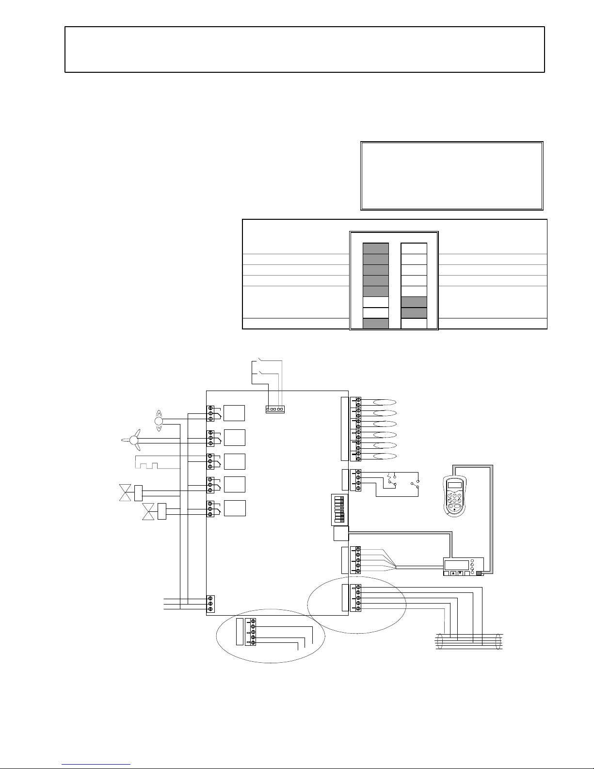
Universal Controller - YAD
Coldroom
ZA-10003-YAD
Issue a : 5/11/96
Product Part No:
• Universal Controller 190797-YAD
Warning !
Before you work on this equipment, isolate the
electrical supply and also the live feed to any
incoming signals. Remember that live signals
may be derived from more than one source.
Features:
• Controls and monitors HT and LT Coldroom
• Genus or alternative network compatible
• Full defrost control
Associated Documents:
∗ Datasheet: ZD 10001-YAD
∗ DIN Box Display: ZF 0920-DIN
∗ Set-up Unit: ZF 0795-DAD
∗ Using Probe Clips: ZG 56003
∗ Health and Safety: ZG 1056
Bit Switch Settings (Fig. 1) : (Shaded area = Switch Position)
Off On
Genus Network 1 Alternative Network
Elm Probes 2 Alternative Probes
Relay 5 -Remote 3 Relay 5 Switches Alarm
Not used....leave off 4 Not used....leave off
5
Coldroom option 6
7
LT Range (Frozen Food)
8
HT Range (Fresh Food)
Please Note:
The features and specifications contained in this
Installation Guide may change without notice.
Elm Ltd. shall not be liable for errors or for
incidental or consequential damages in connection
with the furnishing, performance or use of this
product or document.
Relay
1
Relay
2
Relay
3
Relay
4
Relay
5
Note: This simplified wiring diagram omits circuit protection
ON
1
2
3
4
5
6
7
8
(P6) Logging
(P5) Defrost terminate
(P4) Evaporator out
(P3) Evaporator in
(P2) Air off
(P1) Air on
Temperature Probes -
Bit switches
+
OPTIONS EXECUTE
PAGE
PAGE HOME
SELECT
Setup
Unit
Previous
controller
Next
controller
Genus or alternative
Network cable
-1.5
Ent
Esc
Alarm
Network
Defrost
white
green
red
Plant fault 2
Plant fault 1
N
L
E
Mains
Supply
DIN Box Display
Alarm or controlled remotely
by the Supervisor
Fans
Defrost heater / Drip Pan Heater
Suction line
valve
N/C Liquid line valve
Setup unit extension cable
screen
red
white
black
green
blue
green
yellow
white
red
CN7
CN8
P2
P1
CN9
CN10
CN11
CN12
CN13
CN14
CN15
CN5
CN6
CN4
CN3
CN2
CN1
YAD
Controller on a
Genus Network
screen
white
black
CN7
Controller on a
Woodley Network
Controller
(Fig. 2)
Position of probes should be in accordance
with coil manufacturers instructions
Defrost
Door
open
Closed
5k
If gas defrost is
required, connect N/C S.G.V. to
Relay 3 N/C contact
Page 6
Commissioning:
1. Check all electrical connections (Fig. 2).
2. Make sure that the controller software is
YAD.
3. Check / Set Bit Switches (Fig. 1).
4. Switch the controller ON.
5. Connect Set-up Unit to DIN Box Display
or controller (Fig. 2).
6. Check / Set operating parameters - see
list
7. Save values - if changed
8. Log the controller on to the network then
verify settings on Genus InTouch panel,
Set-up Unit or DIN Box Display.
9. Faults ?..........See ‘Fault Finding’.
Fault Finding:
Set-up Unit does not reach the first
screen.
• If the red LED beside the display
connector is ON or flashing, then the
controller is faulty.
You cannot log the controller on to
the network.
• There may be a controller with the same
name, already logged on the network.
• There may be a maximum 32 controllers
already on the network segment.
• Check on the InTouch panel, P.C. or
Supervisor.
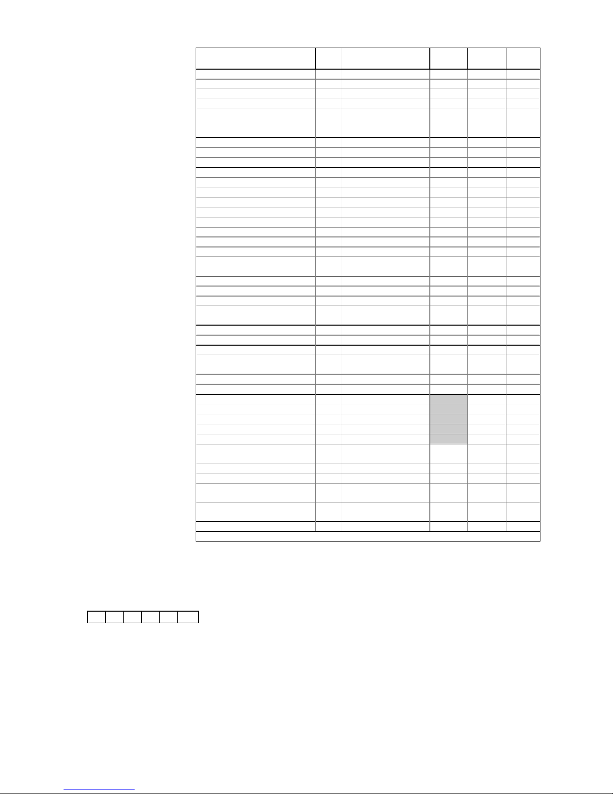
Parameter DIN Range/Units Default
HT(LT)
Dsgn. Act.
Cut in Temperature 0 -49 to 30 / °C 0 (-20)
Differential Below 1 0 to 30 / °C 1.5 (2)
Control Weight 2 0 to 100 / % 50
Display Weight 3 0 to 100 / % 50
Log Probe Type: 0=Off ;
1=Product ; 2=Alarm ;
3=Prod/Alm
8 0 to 3 0
OT Alarm 5 -49 to 60 / °C 5 (-16)
UT Alarm 4 -49 to 60 / °C -2 (-25)
Alarm Delay 6 00:00 to 99:00/Min:Sec 20:00
Log OT Alarm 10 -49 to 60 / °C 5 (-15)
Log UT Alarm 9 -49 to 60 / °C 0 (-25)
Latch Alarm: 0=Off ; 1=On 7 0 to 1 0
Defrost Start 11 00:00 to 23:59/Hrs:Mins 01:00
Number of Defrosts per Day 12 0 to 6 6
No Defrost Time 13 0 to 25 / Hrs. 7
Gas Defrost Detect 14 0 to 30 / °C 18
Defrost Terminate Temperature 15 -49 to 30 / °C 10 (14)
Defrost Minimum Time 16 00:00 to 99:00/Min:Sec 05:00
Defrost Maximum Time 17 00:00 to 99:00/Min:Sec 24:00
(25:00)
Drain Down Time 18 00:00 to 20:00/Min:Sec 01:30
Defrost Min. Recovery Time 19 00:00 to 99:00/Min:Sec 20:00
Defrost Max. Recovery Time 20 00:00 to 99:00/Min:Sec 30:00
Defrost Type: 0=Elect.;1= (2)Gas
2=(3)Gas
23 0 to 2 0
Pump Down 1 21 00:00 to 07:00/Min:Sec 00:00
Pump Down 2 22 00:00 to 07:00/Min:Sec 00:00
Defrost Alarm Temp. 24 -49 to 60 / °C 20
Defrost Mode: 0=Local ;
1=Remote
25 0 to 1 0
Defrost Hold: 0=Off ; 1=On 26 0 to 1 0
Pulse Defrost: 0=Off ; 1=On 27 0 to 1 0
Hour 28 0 to 23
Minute 29 0 to 59
Day 30 0 to 31
Month 31 0 to 12
Year 32 0 to 99
BST / GMT Select: 0=Auto ;
1=Man.Off ; 2=Man.On
33 0 to 2 0
Door Alarm Delay 34 00:00 to 99:00/Min:Sec 20:00
Drip Pan Heater: 0=Off ; 1=On 35 0 to 1 0
Fans Off when Door Open: 0=Off
1=On
36 0 to 1 0
Liquid Line Closed when Door
Open: 0=Off ; 1=On
37 0 to 1 0
Manual Defrost: 0=Off ; 1=On 99 0 to 1 0
YAD08c / 65EAEE
Display Alarm Messages:
AL Temperature alarm
Ft Probes 1 and 2 are faulty
LA Log probe alarm
Pn probe ‘n’ faulty or not connected
(Where ‘n’ = probe number)
EE EEPROM fault
rr Internal program fault
E1 Plant fault 1
E2 Plant fault 2
ES Energy-Saving Mode
Store:.............................................
Controller
Name:
Designer:........................................
Date:..............................................
Engineer:........................................
Date:..............................................
Comments:
Universal Controller -
Coldroom
ZA-10003-YAD
Issue a : 5/11/96
Page 7
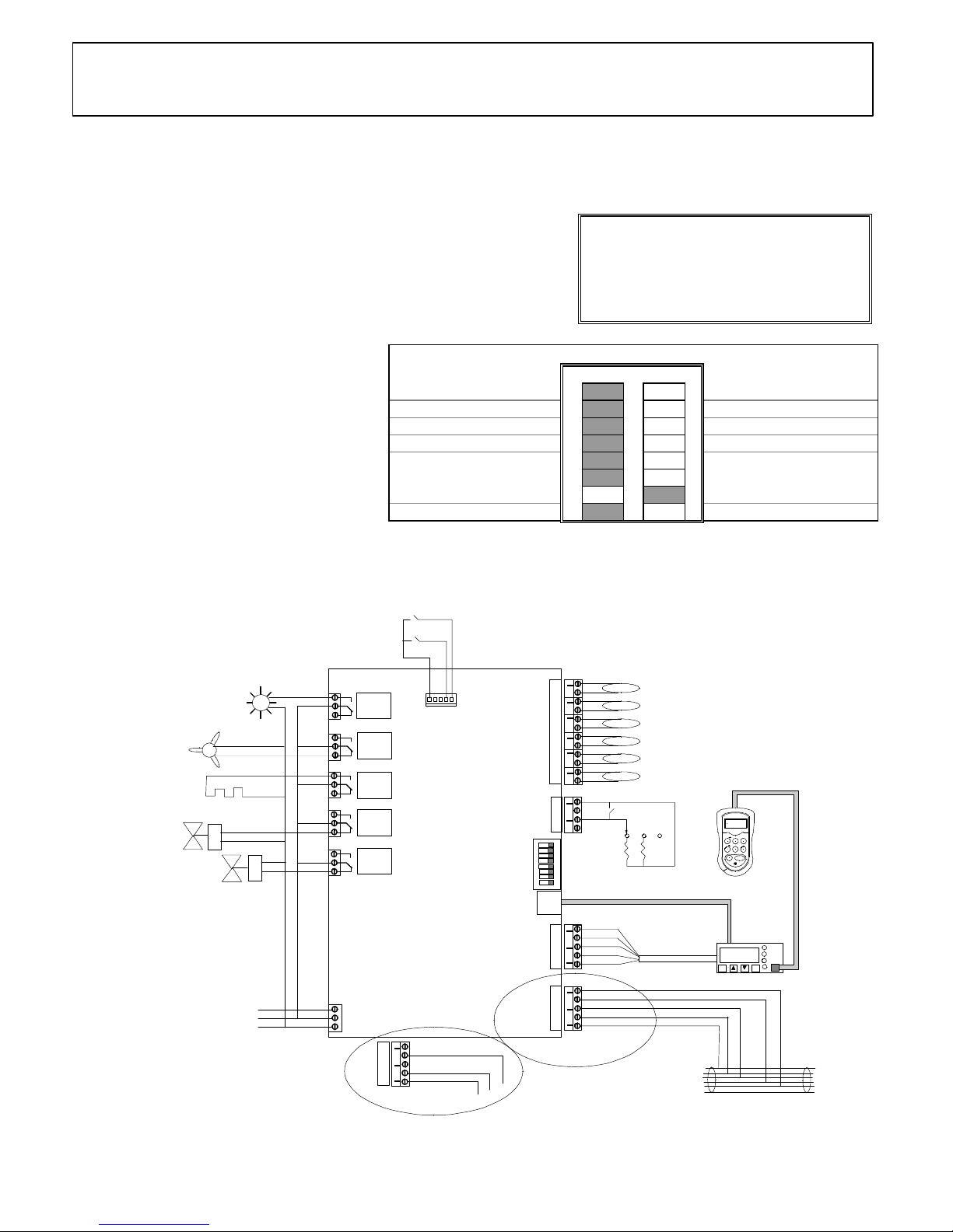
Universal Controller - YAD
3 Range
ZA-10004-YAD
Issue a : 5/11/96
Bit Switch Settings (Fig. 1) : (Shaded area = Switch Position)
Off On
Genus Network 1 Alternative Network
Elm Probes 2 Alternative Probes
Relay 5 switches lights 3 Relay 5 Switches Alarm
Not used....leave off 4 Not used....leave off
5
3 Range case option 6
7
LT Range (Frozen Food)
8
HT Range (Fresh Food)
Warning !
Before you work on this equipment, isolate the
electrical supply and also the live feed to any
incoming signals. Remember that live signals
may be derived from more than one source.
Relay
1
Relay
2
Relay
3
Relay
4
Relay
5
Note: This simplified wiring diagram omits circuit protection
ON
1
2
3
4
5
6
7
8
(P6) Logging
(P5) Honeycomb
(P4) Evaporator out
(P3) Evaporator in
(P2) Air off
(P1) Air on
Temperature Probes -
Bit switches
+
OPTIONS EXECUTE
PAGE
PAGE HOME
SELECT
Setup
Unit
Previous
controller
Next
controller
Genus or alternative
Network cable
-1.5
Ent
Esc
Alarm
Network
Defrost
Defrost
Fans
only
Case
off
Normal
white
green
red
Plant fault 2
Plant fault 1
N
L
E
Mains
Supply
DIN Box Display
Fans
Suction line
valve
N/C Liquid line valve
Setup unit extension cable
screen
red
white
black
green
blue
green
yellow
white
red
CN7
CN8
P2
P1
CN9
CN10
CN11
CN12
CN13
CN14
CN15
CN5
CN6
CN4
CN3
CN2
CN1
YAD
Controller on a
Genus Network
screen
white
black
CN7
Controller on a
Woodley Network
Controller
(Fig. 2)
Position of probes should be in accordance
with case manufacturers instructions
10k
5k
Case lights /
blinds
Alarm wired to Relay 5 N/C
contact if bit switch 3 is ON
If gas defrost is
required, connect
N/C S.G.V. to
Relay 3 N/C contact
Defrost Heater
Product Part No:
• Universal Controller 190797-YAD
Features:
• Controls and monitors HT and LT 3 Range case
• Genus or alternative network compatible
• Full defrost control
Associated Documents:
∗ Datasheet: ZD 10001-YAD
∗ DIN Box Display: ZF 0920-DIN
∗ Set-up Unit: ZF 0795-DAD
∗ Using Probe Clips: ZG 56003
∗ Health and Safety: ZG 1056
Please Note:
The features and specifications contained in this
Installation Guide may change without notice.
Elm Ltd. shall not be liable for errors or for incidental or
consequential damages in connection with the
furnishing, performance or use of this product or
document.
Page 8
Commissioning:
1. Check all electrical connections (Fig. 2).
2. Make sure that the controller software is
YAD.
3. Check / Set Bit Switches (Fig. 1).
4. Switch the controller ON.
5. Connect Set-up Unit to DIN Box Display
or controller (Fig. 2).
6. Check / Set operating parameters - see
list
7. Save values - if changed
8. Log the controller on to the network then
verify settings on Genus InTouch panel,
Set-up Unit or DIN Box Display.
9. Faults ?..........See ‘Fault Finding’.
Fault Finding:
Set-up Unit does not reach the first
screen.
• If the red LED beside the display
connector is ON or flashing, then the
controller is faulty.
You cannot log the controller on to
the network.
• There may be a controller with the same
name, already logged on the network.
• There may be a maximum 32 controllers
already on the network segment.
• Check on the InTouch panel, P.C. or
Supervisor.
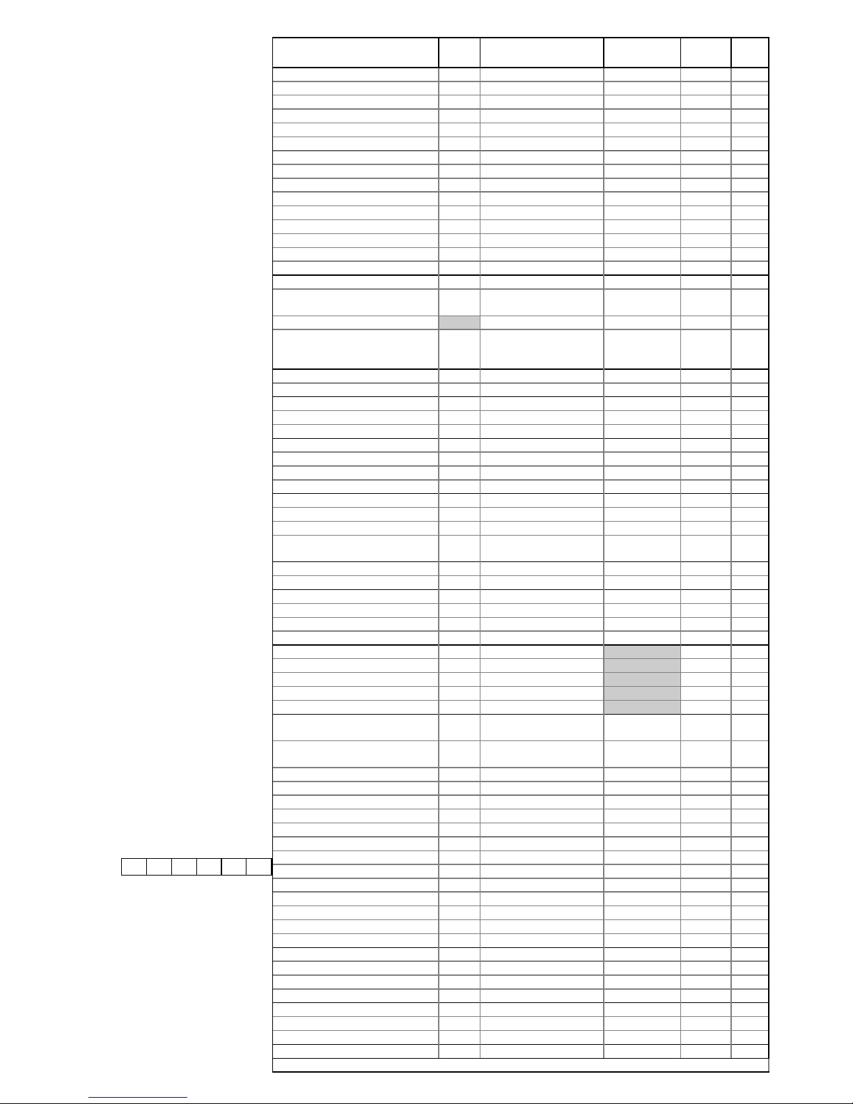
Parameter DIN Range/Units Default
HT(LT)
Dsgn. Act.
Red Cycle Temperature 0 1 to 7 (-49 to 60) / °C 4 (-22)
Red OT Alarm Temp. 2 7 to 10 (-49 to 60) / °C 8 (-15)
Red UT Alarm Temp. 1 -3 to 4 (-49 to 60) / °C 2 (-30)
Yellow Cycle Temperature 3 -1 to4 (-49 to 60) / °C 1 (-22)
Yellow OT Alarm Temp. 5 4 to 7 (-49 to 60) / °C 5 (-15)
Yellow UT Alarm Temp. 4 -6 to 1 (-49 to 60) / °C -1 (-30)
White Cycle Temperature 6 4 to 12 (-49 to 60) /°C 8 (-22)
White OT Alarm Temp. 8 11 to 14 (-49 to 60) / °C 12 (-15)
White UT Alarm Temp. 7 1 to 6 (-49 to 60) / °C 4 (-30)
Red Log OT Alarm 15 8 to 10 (-49 to 60) / °C 8(-15)
Red Log UT Alarm 14 -1 to 4 (-49 to 60) / °C 2(-25)
Yellow Log OT Alarm 17 5 to 7 (-49 to 60) / °C 5(-15)
Yellow Log UT Alarm 16 -2 to 1 (-49 to 60) / °C 0(-25)
White Log OT Alarm 19 12 to 14 (-49 to 60) / °C 12(-15)
White Log UT Alarm 18 3 to 7 (-49 to 60) / °C 4(-25)
Cycle Differential 10 0.5 to 4 / °C 1.5(2.0)
Case Type: 0=Red ; 1=Yellow ;
2=White
9 0 to 2 0
Alarm Delay Fixed / Min:Sec 05:00 (10:00)
Log Probe Type: 0=Off ;
1=Product ; 2=Alarm ;
3=Prod./Alarm
13 0 to 3 0
Control Weight 11 0 to 100 / % 50
Display Weight 12 0 to 100 / % 50
Defrost Start 21 00:00 to 23:59/Hrs:Mins 01:00
Number of Defrosts per Day 22 0 to 6 6
No Defrost Time 23 0 to 25 / Hrs. 7
Gas Defrost Detect 24 10 to 30 / °C 18.0
Defrost Minimum Time 26 00:00 to 05:00/Min:Sec 05:00
Defrost Maximum Time 27 00:00 to 26:00/Min:Sec 24:00 (25:00)
Defrost Terminate Temperature 25 6 to 14 / °C 10 (14)
Drain Down Time 28 00:00 to 03:00/Min:Sec 01:30
Defrost Min.Recovery Time 29 00:00 to 35:00/Min:Sec 20:00
Defrost Max.Recovery Time 30 15:00 to 35:00/Min:Sec 30:00
Defrost Type: 0=Elect.;1= (2)Gas
2=(3)Gas
35 0 to 2 0
Pump Down 1 31 00:00 to 07:00/Min:Sec 00:00
Pump Down 2 32 00:00 to 07:00/Min:Sec 00:00
Defrost Alarm Temp. 33 -49 to 60 / °C 20
Defrost Mode:0=Local;1=Remote 34 0 to 1 0
Defrost Hold: 0=Off ; 1=On 36 0 to 1 0
Pulse Defrost: 0=Off ; 1=On 37 0 to 1 0
Hour 38 0 to 23
Minute 39 0 to 59
Day 40 0 to 31
Month 41 0 to 12
Year 42 0 to 99
BST / GMT Select: 0=Auto ;
1=Man.Off ; 2=Man.On
43 0 to 2 0
Lights/Blind: 0=Local ;1=Remote
; 2=Man.Off ; 3=Man.On
44 0 to 3 0
Polarity: 0=N/O ; 1=N/C 45 0 to 1 0
Alarm Latch: 0=Off ; 1=On 20 0 to 1 0
Sunday (Blinds) Up / Down 46/47 00:00 to 23:59/Hrs:Mins 08:00/20:00
Monday (Blinds) Up / Down 48/49 00:00 to 23:59/Hrs:Mins 08:00/20:00
Tuesday (Blinds) Up / Down 50/51 00:00 to 23:59/Hrs:Mins 08:00/20:00
Wednesday (Blinds) Up / Down 52/53 00:00 to 23:59/Hrs:Mins 08:00/20:00
Thursday (Blinds) Up / Down 54/55 00:00 to 23:59/Hrs:Mins 08:00/20:00
Friday (Blinds) Up / Down 56/57 00:00 to 23:59/Hrs:Mins 08:00/20:00
Saturday (Blinds) Up / Down 58/59 00:00 to 23:59/Hrs:Mins 08:00/20:00
Energy Saving: 0=Off ; 1=On 60 0 to 1 0
Entry Diff. 61 -49 to 60 / °C 4
Exit Diff. 62 -49 to 60 / °C 8
Exit Tme 63 00:00 to 20:00/Min:Sec 00:30
Cycle Temp. 64 -49 to 60 / °C 5
Fan Diff. 65 0 to 60 / °C 4
Run on Time 66 00:00 to 20:00/Min:Sec 05:00
Def. Term. 67 -49 to 30 / °C 14
Gas Alarm: 0=Off ; 1=On 68 0 to 1 0
Minor Leak 69 0 to 3500 / ppm. 50
Major Leak 70 0 to 3500 / ppm. 200
Manual Defrost: 0=Off ; 1=On 99 0 to 1 0
YAD08y / 65EAEE
Display Alarm Messages:
AL Temperature alarm
Ft Probes 1 and 2 are faulty
LA Log probe alarm
Pn probe ‘n’ faulty or not connected
(Where ‘n’ = probe number)
EE EEPROM fault
rr Internal program fault
E1 Plant fault 1
E2 Plant fault 2
ES Energy-Saving Mode
Store:............................................
Controller
Name:
Designer:.....................................
Date:............................................
Engineer:......................................
Date:.............................................
Comments:
Universal Controller -
3 Range
ZA-10004-YAD
Issue a : 5/11/96
Page 9
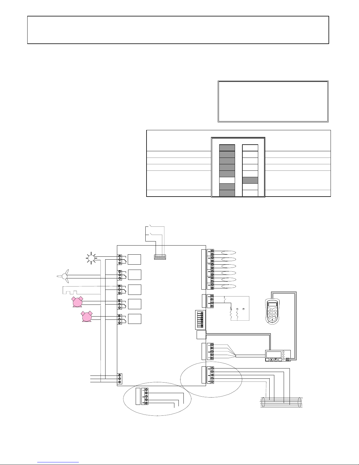
Universal Controller - YAD
Dyadic
ZA-10005-YAD
Issue a :5/11/96
Bit Switch Settings (Fig. 1) : (Shaded area = Switch Position)
Off On
Genus Network 1 Alternative Network
Elm Probes 2 Alternative Probes
Relay 5 switches lights 3 Relay 5 Switches Alarm
Not used....leave off 4 Not used....leave off
5
Dyadic case option 6
7
Not used....leave off
8
Not used....leave off
Warning !
Before you work on this equipment, isolate the
electrical supply and also the live feed to any
incoming signals. Remember that live signals
may be derived from more than one source.
Relay
1
Relay
2
Relay
3
Relay
4
Relay
5
Note: This simplified wiring diagram omits circuit protection
ON
1
2
3
4
5
6
7
8
(P6) Logging
(P5) Honeycomb
(P4) Evaporator out
(P3) Evaporator in
(P2) Air off
(P1) Air on
Temperature Probes -
Bit switches
+
OPTIONS EXECUTE
PAGE
PAGE HOME
SELECT
Setup
Unit
Previous
controller
Next
controller
Genus or alternative
Network cable
-1.5
Ent
Esc
Alarm
Network
Defrost
Defrost
Fans
only
Case
off
Normal
white
green
red
Plant fault 2
Plant fault 1
N
L
E
Mains
Supply
DIN Box Display
Fans
Setup unit extension cable
screen
red
white
black
green
blue
green
yellow
white
red
CN7
CN8
P2
P1
CN9
CN10
CN11
CN12
CN13
CN14
CN15
CN5
CN6
CN4
CN3
CN2
CN1
YAD
Controller on a
Genus Network
screen
white
black
CN7
Controller on a
Woodley Network
Controller
(Fig. 2)
Position of probes should be in accordance
with case manufacturers instructions
10k
5k
Compressor B
Compressor A
Defrost heater
Case lights /
blinds
Alarm wired to Relay 5 N/C
contact if bit switch 3 is ON
Product Part No:
• Universal Controller 190797-YAD
Features:
• Controls and monitors Dyadic case
• Genus or alternative network compatible
• Full defrost control
Associated Documents:
∗ Datasheet: ZD 10001-YAD
∗ DIN Box Display: ZF 0920-DIN
∗ Set-up Unit: ZF 0795-DAD
∗ Using Probe Clips: ZG 56003
∗ Health and Safety: ZG 1056
Please Note:
The features and specifications contained in this
Installation Guide may change without notice.
Elm Ltd. shall not be liable for errors or for incidental or
consequential damages in connection with the
furnishing, performance or use of this product or
document.
Page 10
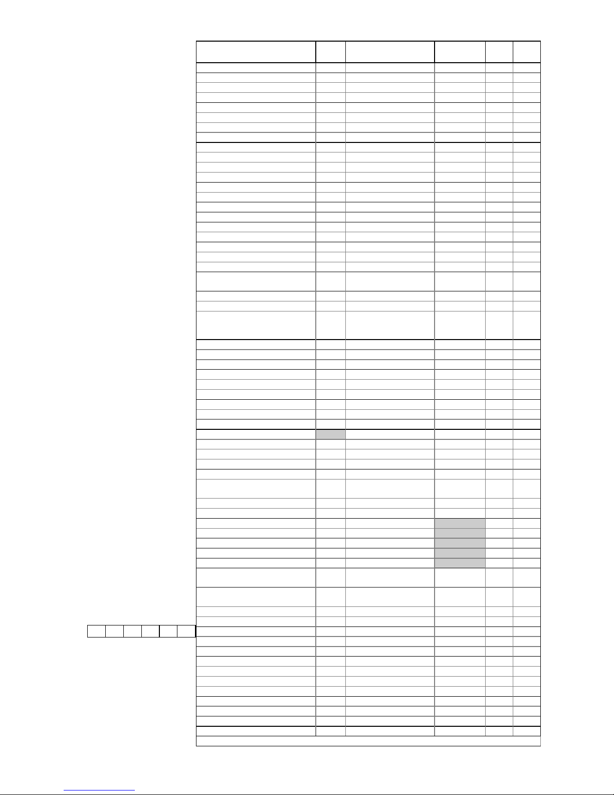
Commissioning:
1. Check all electrical connections (Fig. 2).
2. Make sure that the controller software is
YAD.
3. Check / Set Bit Switches (Fig. 1).
4. Switch the controller ON.
5. Connect Set-up Unit to DIN Box Display
or controller (Fig. 2).
6. Check / Set operating parameters - see
list
7. Save values - if changed
8. Log the controller on to the network then
verify settings on Genus InTouch panel,
Set-up Unit or DIN Box Display.
9. Faults ?..........See ‘Fault Finding’.
Fault Finding:
Set-up Unit does not reach the first
screen.
• If the red LED beside the display
connector is ON or flashing, then the
controller is faulty.
You cannot log the controller on to
the network.
• There may be a controller with the same
name, already logged on the network.
• There may be a maximum 32 controllers
already on the network segment.
• Check on the InTouch panel, P.C. or
Supervisor.
Parameter DIN Range/Units Default
Setting
Dsgn.Act.
Red Cycle Temperature 0 1 to 7 / °C 4
Red OT Alarm Temp. 2 7 to 10 / °C 8
Red UT Alarm Temp. 1 -3 to 4 / °C 2
Defrost Type:0=Elect.;1=Off Cyc. 3 0 to 1 0
Yellow Cycle Temperature 4 -1 to 4 / °C 1
Yellow OT Alarm Temp. 6 4 to 7 / °C 5
Yellow UT Alarm Temp. 5 -6 to 1 / °C -1
Defrost Type:0=Elect.;1=Off Cyc. 7 0 to 1 0
White Cycle Temperature 8 4 to 12 / °C 8
White OT Alarm Temp. 10 11 to 14 / °C 12
White UT Alarm Temp. 9 1 to 6 / °C 4
Defrost Type:0=Elect.;1=Off Cyc. 11 0 to 1 1
Red Log OT Alarm 20 8 to 10 / °C 8
Red Log UT Alarm 19 -1 to 4 / °C 2
Yellow Log OT Alarm 22 5 to 7 / °C 5
Yellow Log UT Alarm 21 -2 to 1 / °C 0
White Log OT Alarm 24 12 to 14 / °C 12
White Log UT Alarm 23 3 to 7 / °C 4
Lead Cyc. Diff 12 0 to 30 / °C 1.5
Lag. Cut In 13 0 to 3 / °C 1
Lag Cut Out 14 0 to 3 / °C 1
Case Type: 0=Red ; 1=Yellow ;
2=White
16 0 to 2 0
Control Weight 15 0 to 100 / % 50
Display Weight 16 0 to 100 / % 50
Log Probe Type: 0=Off ;
1=Product ; 2=Alarm ;
3=Prod./Alarm
18 0 to 3 0
Off Cycle Defrost Max.Temp. 30 -49 to 60 / °C 10
Off Cycle Defrost Minimum Time 28 00:00 to 99:00/Min:Sec 05:00
Off Cycle Defrost Maximum Time 29 00:00 to 99:00/Min:Sec 24:00
Electric Defrost Max. Temp. 33 -49 to 60 / °C 10
Electric Defrost Minimum Time 31 00:00 to 99:00/Min:Sec 05:00
Electric Defrost Maximum Time 32 00:00 to 99:00/Min:Sec 24:00
Defrost Start 26 00:00 to 23:59/Hrs:Mins 01:00
Number of Defrosts per Day 27 0 to 6 6
No Defrost Time 41 0 to 25/ Hrs. 7
Alarm Delay Fixed / Min:Sec 05:00
Drain Down Time 34 00:00 to 03:00/Min:Sec 01:30
Defrost Min. Recovery Time 35 00:00 to 35:00/Min:Sec 20:00
Defrost Max. Recovery Time 36 15:00 to 35:00/Min:Sec 30:00
Defrost Alarm Temp. 37 -49 to 60 / °C 20
Defrost Mode: 0=Local ;
1=Remote
38 0 to 1 0
Defrost Hold: 0=Off ; 1=On 40 0 to 1 0
Pulse Defrost: 0=Off ; 1=On 39 0 to 1 0
Hour 42 0 to 23
Minute 43 0 to 59
Day 44 0 to 31
Month 45 0 to 12
Year 46 0 to 99
BST / GMT Select: 0=Auto ;
1=Man.Off ; 2=Man.On
47 0 to 2 0
Lights/Blind: 0=Local ; 1=Remote
; 2=Man.Off ; 3=Man.On
48 0 to 3 0
Polarity: 0=N/O ; 1=N/C 49 0 to 1 0
Latch Alarm: 0=Off ; 1=On 25 0 to 1 0
Sunday (Blinds) Up / Down 50/51 00:00 to 23:59/Hrs:Mins 08:00/20:00
Monday (Blinds) Up / Down 52/53 00:00 to 23:59/Hrs:Mins 08:00/20:00
Tuesday (Blinds) Up / Down 54/55 00:00 to 23:59/Hrs:Mins 08:00/20:00
Wednesday (Blinds) Up / Down 56/57 00:00 to 23:59/Hrs:Mins 08:00/20:00
Thursday (Blinds) Up / Down 58/59 00:00 to 23:59/Hrs:Mins 08:00/20:00
Friday (Blinds) Up / Down 60/61 00:00 to 23:59/Hrs:Mins 08:00/20:00
Saturday (Blinds) Up / Down 62/63 00:00 to 23:59/Hrs:Mins 08:00/20:00
Gas Alarm: 0=Off ; 1=On 64 0 to 1 0
Minor Leak 65 0 to 3500 / ppm. 50
Major Leak 66 0 to 3500 / ppm. 200
Manual Defrost: 0=Off ; 1=On 99 0 to 1 0
YAD08d / 65EAEE
Display Alarm Messages:
AL Temperature alarm
Ft Probes 1 and 2 are faulty
LA Log probe alarm
Pn probe ‘n’ faulty or not connected
(Where ‘n’ = probe number)
EE EEPROM fault
rr Internal program fault
E1 Plant fault 1
E2 Plant fault 2
ES Energy-Saving Mode
Store:............................................
Controller
Name:
Designer:.....................................
Date:............................................
Engineer:......................................
Date:.............................................
Comments:
Universal Controller -
Dyadic
ZA-10005-YAD
Issue a : 5/11/96
Page 11
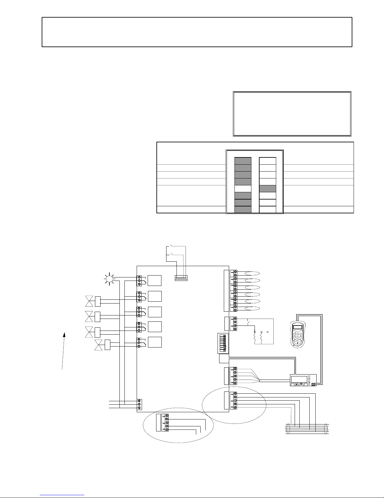
Universal Controller - YAD
3 Section
Relay
1
Relay
2
Relay
3
Relay
4
Relay
5
Note: This simplified wiring diagram omits circuit protection
ON
1
2
3
4
5
6
7
8
(P6) Air off - Section 3
(P5) Air on - Section 3
(P4) Air off - Section 2
(P3) Air on - Section 2
(P2) Air off - Section 1
(P1) Air on - Section 1
Temperature Probes -
Bit switches
+
OPTIONS EXECUTE
PAGE
PAGE HOME
SELECT
Setup
Unit
Previous
controller
Next
controller
Genus or alternative
Network cable
-1.5
Ent Esc
Alarm
Network
Defrost
Defrost
Fans
only
Case
off
Normal
white
green
red
Plant fault 2
Plant fault 1
N
L
E
Mains
Supply
DIN Box Display
Suction line
valve 1
N/C Liquid line valve
Setup unit extension cable
screen
red
white
black
green
blue
green
yellow
white
red
CN7
CN8
P2
P1
CN9
CN10
CN11
CN12
CN13
CN14
CN15
CN5
CN6
CN4
CN3
CN2
CN1
YAD
Controller on a
Genus Network
screen
white
black
CN7
Controller on a
Woodley Network
Controller
(Fig. 2)
Position of probes should be in accordance
with case manufacturers instructions
10k
5k
Suction line
valve 2
Suction line
valve 3
*
*
*
If Electric Defrost Heater is
required, connect to N/O
contact
*
Case lights /
blinds
Alarm wired to Relay 5 N/C
contact if bit switch 3 is ON
ZA-10006-YAD
Issue a : 5/11/96
Product Part No:
• Universal Controller 190797-YAD
Warning !
Before you work on this equipment, isolate the
electrical supply and also the live feed to any
incoming signals. Remember that live signals
may be derived from more than one source.
Features:
• Controls and monitors HT and LT 3 Section case
• Genus or alternative network compatible
• Full defrost control
Associated Documents:
∗ Datasheet: ZD 10001-YAD
∗ DIN Box Display: ZF 0920-DIN
∗ Set-up Unit: ZF 0795-DAD
∗ Using Probe Clips: ZG 56003
∗ Health and Safety: ZG 1056
Bit Switch Settings (Fig. 1) : (Shaded area = Switch Position)
Off On
Genus Network 1 Alternative Network
Elm Probes 2 Alternative Probes
Relay 5 switches lights 3 Relay 5 Switches Alarm
Not used....leave off 4 Not used....leave off
5
3 Section case option 6
7
LT Range (Frozen Food)
8
HT Range (Fresh Food)
Please Note:
The features and specifications contained in this
Installation Guide may change without notice.
Elm Ltd. shall not be liable for errors or for
incidental or consequential damages in connection
with the furnishing, performance or use of this
product or document.
Page 12
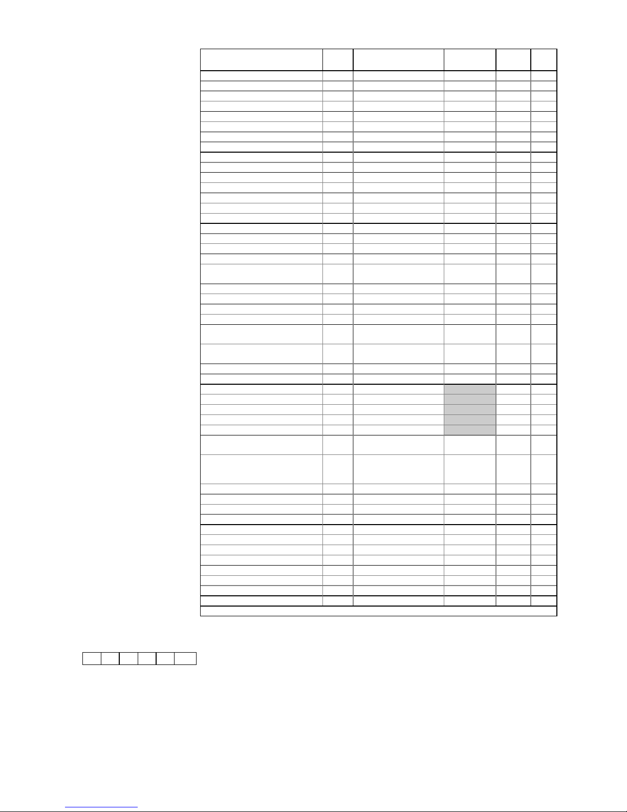
Commissioning:
1. Check all electrical connections (Fig. 2).
2. Make sure that the controller software is
YAD.
3. Check / Set Bit Switches (Fig. 1).
4. Switch the controller ON.
5. Connect Set-up Unit to DIN Box Display
or controller (Fig. 2).
6. Check / Set operating parameters - see
list
7. Save values - if changed
8. Log the controller on to the network then
verify settings on Genus InTouch panel,
Set-up Unit or DIN Box Display.
9. Faults ?..........See ‘Fault Finding’.
Fault Finding:
Set-up Unit does not reach the first
screen.
• If the red LED beside the display
connector is ON or flashing, then the
controller is faulty.
You cannot log the controller on to
the network.
• There may be a controller with the same
name, already logged on the network.
• There may be a maximum 32 controllers
already on the network segment.
• Check on the InTouch panel, P.C. or
Supervisor.
Parameter DIN Range/Units Default
HT(LT)
Dsgn Act.
Cut in Temperature 0 -49 to 30 / °C 0 (-20)
Differential Below 1 0 to 30 / °C 1.5 (2)
Control Weight 2 0 to 100 / % 50
Display Weight 3 0 to 100 / % 50
Section 1: OT Alarm 44 -49 to 60 / °C 5 (-16)
Section 1: UT Alarm 45 -49 to 60 / °C -2 (-25)
Section 2: OT Alarm 47 -49 to 60 / °C 5 (-16)
Section 2: UT Alarm 48 -49 to 60 / °C -2 (-25)
Section 3: OT Alarm 50 -49 to 60 / °C 5 (-16)
Section 3: UT Alarm 51 -49 to 60 / °C -2 (-25)
Alarm Delay 17 00:00 to 99:00/Min:Sec 20:00
Latch Alarm: 0=Off ; 1=On 18 0 to 1 0
Defrost Start 4 00:00 to 23:59/Hrs:Mins 01:00
Number of Defrosts per Day 5 0 to 6 6
No Defrost Time 6 0 to 25 / Hrs. 7
Section 1: Defrost Term. Temp. 46 -49 to 60 / °C 10
Section 2: Defrost Term. Temp. 49 -49 to 60 / °C 10
Section 3: Defrost Term. Temp. 52 -49 to 60 / °C 10
Defrost Minimum Time 7 00:00 to 99:00/Min:Sec 05:00
Defrost Maximum Time 8 00:00 to 99:00/Min:Sec 24:00
(25:00)
Defrost Min. Recovery Time 9 00:00 to 99:00/Min:Sec 20:00
Defrost Max. Recovery Time 10 00:00 to 99:00/Min:Sec 30:00
Drain Down Time 11 00:00 to 20:00/Min:Sec 01:30
Defrost Alarm Temp. 12 -49 to 60 / °C 20
Defrost Type: 0=Elect.;1= (2)Gas
2=(3)Gas
13 0 to 2 0
Defrost Mode: 0=Local ;
1=Remote
14 0 to 1 0
Defrost Hold: 0=Off ; 1=On 15 0 to 1 0
Pulse Defrost: 0=Off ; 1=On 16 0 to 1 0
Hour 19 0 to 23
Minute 20 0 to 59
Day 21 0 to 31
Month 22 0 to 12
Year 23 0 to 99
BST / GMT Select: 0=Auto ;
1=Man.Off ; 2=Man.On
24 0 to 2 0
Lights/Blinds: 0=Local ;
1=Remote ; 2=Man.Off ;
3=Man.On
25 0 to 3 0
Polarity: 0=N/O ; 1=N/C 26 0 to 1 0
Sunday (Blinds) Up / Down 27/28 00:00 to 23:59/Hrs:Mins 08:00/20:00
Monday Up / Down 29/30 00:00 to 23:59/Hrs:Mins 08:00/20:00
Tuesday Up / Down 31/32 00:00 to 23:59/Hrs:Mins 08:00/20:00
Wednesday Up / Down 33/34 00:00 to 23:59/Hrs:Mins 08:00/20:00
Thursday Up / Down 35/36 00:00 to 23:59/Hrs:Mins 08:00/20:00
Friday Up / Down 37/38 00:00 to 23:59/Hrs:Mins 08:00/20:00
Saturday Up / Down 39/40 00:00 to 23:59/Hrs:Mins 08:00/20:00
Gas Alarm: 0=Off ; 1=On 41 0 to 1 0
Minor Leak 42 0 to 3500 / ppm. 50
Major Leak 43 0 to 3500 / ppm. 200
Manual Defrost: 0=Off ; 1=On 99 0 to 1 0
YAD08t / 65EAEE
Display Alarm Messages:
AL Temperature alarm
Ft Probes 1 and 2 are faulty
LA Log probe alarm
Pn probe ‘n’ faulty or not connected
(Where ‘n’ = probe number)
EE EEPROM fault
rr Internal program fault
E1 Plant fault 1
E2 Plant fault 2
ES Energy-Saving Mode
Store:.............................................
Controller
Name:
Designer:........................................
Date:..............................................
Engineer:........................................
Date:..............................................
Comments:
Universal Controller -
3 Section
ZA-10006-YAD
Issue a : 5/11/96
Page 13
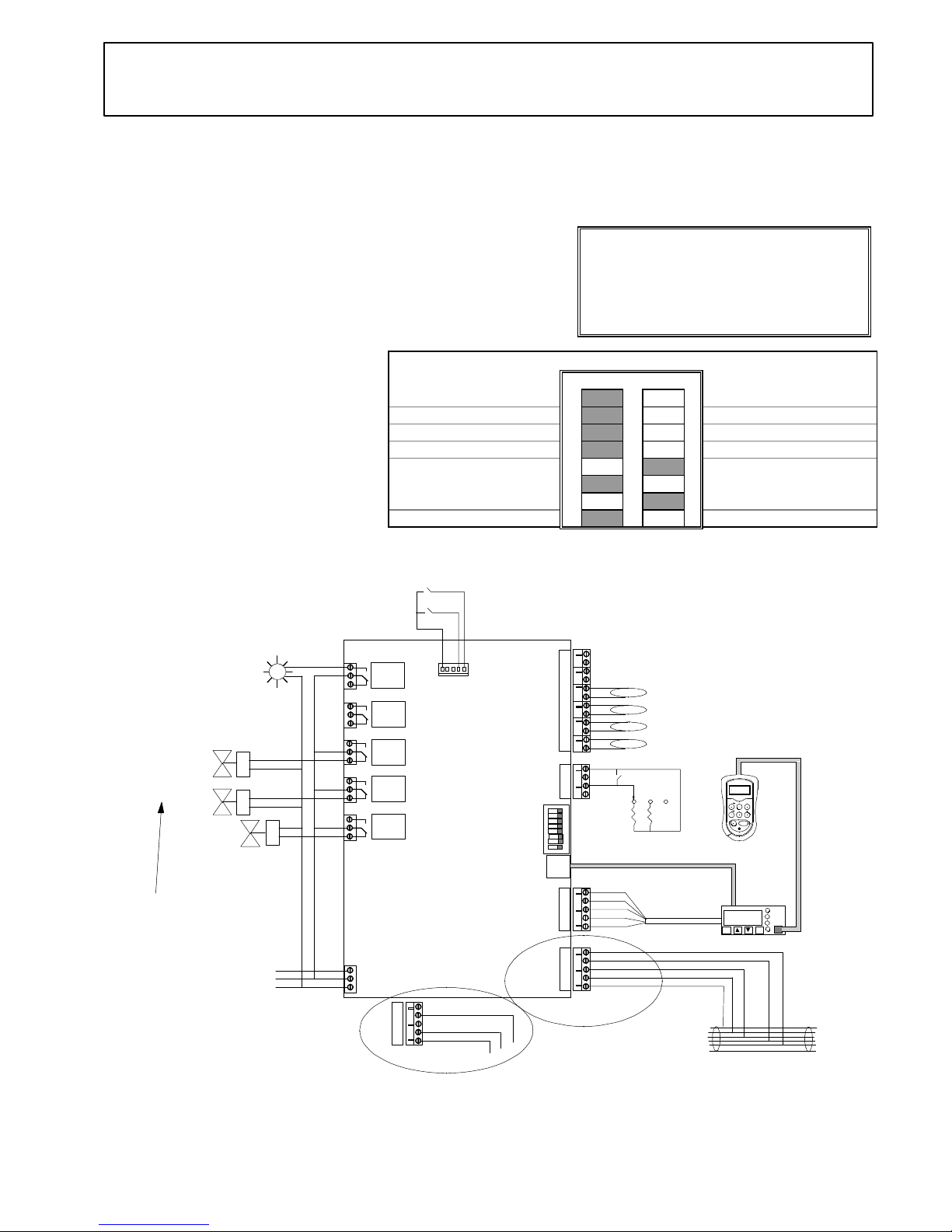
Universal Controller - YAD
2 Section
Relay
1
Relay
2
Relay
3
Relay
4
Relay
5
Note: This simplified wiring diagram omits circuit protection
ON
1
2
3
4
5
6
7
8
(P4) Air off - Section 2
(P3) Air on - Section 2
(P2) Air off - Section 1
(P1) Air on - Section 1
Temperature Probes -
Bit switches
+
OPTIONS EXECUTE
PAGE
PAGE HOME
SELECT
Setup
Unit
Previous
controller
Next
controller
Genus or alternative
Network cable
-1.5
Ent
Esc
Alarm
Network
Defrost
Defrost
Fans
only
Case
off
Normal
white
green
red
Plant fault 2
Plant fault 1
N
L
E
Mains
Supply
DIN Box Display
Suction line
valve 1
N/C Liquid line valve
Setup unit extension cable
screen
red
white
black
green
blue
green
yellow
white
red
CN7
CN8
P2
P1
CN9
CN10
CN11
CN12
CN13
CN14
CN15
CN5
CN6
CN4
CN3
CN2
CN1
YAD
Controller on a
Genus Network
screen
white
black
CN7
Controller on a
Woodley Network
Controller
(Fig. 2)
Position of probes should be in accordance
with case manufacturers instructions
10k
5k
Suction line
valve 2
*
If Electric Defrost Heater is
required, connect to N/O
contact
*
*
Case lights /
blinds
Alarm wired to Relay 5 N/C
contact if bit switch 3 is ON
ZA-10053-YAD
Issue a : 5/11/96
Product Part No:
• Universal Controller 190797-YAD
Warning !
Before you work on this equipment, isolate the
electrical supply and also the live feed to any
incoming signals. Remember that live signals
may be derived from more than one source.
Features:
• Controls and monitors HT and LT 2 Section case
• Genus or alternative network compatible
• Full defrost control
Associated Documents:
∗ Datasheet: ZD 10001-YAD
∗ DIN Box Display: ZF 0920-DIN
∗ Set-up Unit: ZF 0795-DAD
∗ Using Probe Clips: ZG 56003
∗ Health and Safety: ZG 1056
Bit Switch Settings (Fig. 1) : (Shaded area = Switch Position)
Off On
Genus Network 1 Alternative Network
Elm Probes 2 Alternative Probes
Relay 5 switches lights 3 Relay 5 Switches Alarm
Not used....leave off 4 Not used....leave off
5
2 Section case option 6
7
LT Range (Frozen Food)
8
HT Range (Fresh Food)
Please Note:
The features and specifications contained in this
Installation Guide may change without notice.
Elm Ltd. shall not be liable for errors or for
incidental or consequential damages in connection
with the furnishing, performance or use of this
product or document.
Page 14
Commissioning:
1. Check all electrical connections (Fig. 2).
2. Make sure that the controller software is
YAD.
3. Check / Set Bit Switches (Fig. 1).
4. Switch the controller ON.
5. Connect Set-up Unit to DIN Box Display
or controller (Fig. 2).
6. Check / Set operating parameters - see
list
7. Save values - if changed
8. Log the controller on to the network then
verify settings on Genus InTouch panel,
Set-up Unit or DIN Box Display.
9. Faults ?..........See ‘Fault Finding’.
Fault Finding:
Set-up Unit does not reach the first
screen.
• If the red LED beside the display
connector is ON or flashing, then the
controller is faulty.
You cannot log the controller on to
the network.
• There may be a controller with the same
name, already logged on the network.
• There may be a maximum 32 controllers
already on the network segment.
• Check on the InTouch panel, P.C. or
Supervisor.
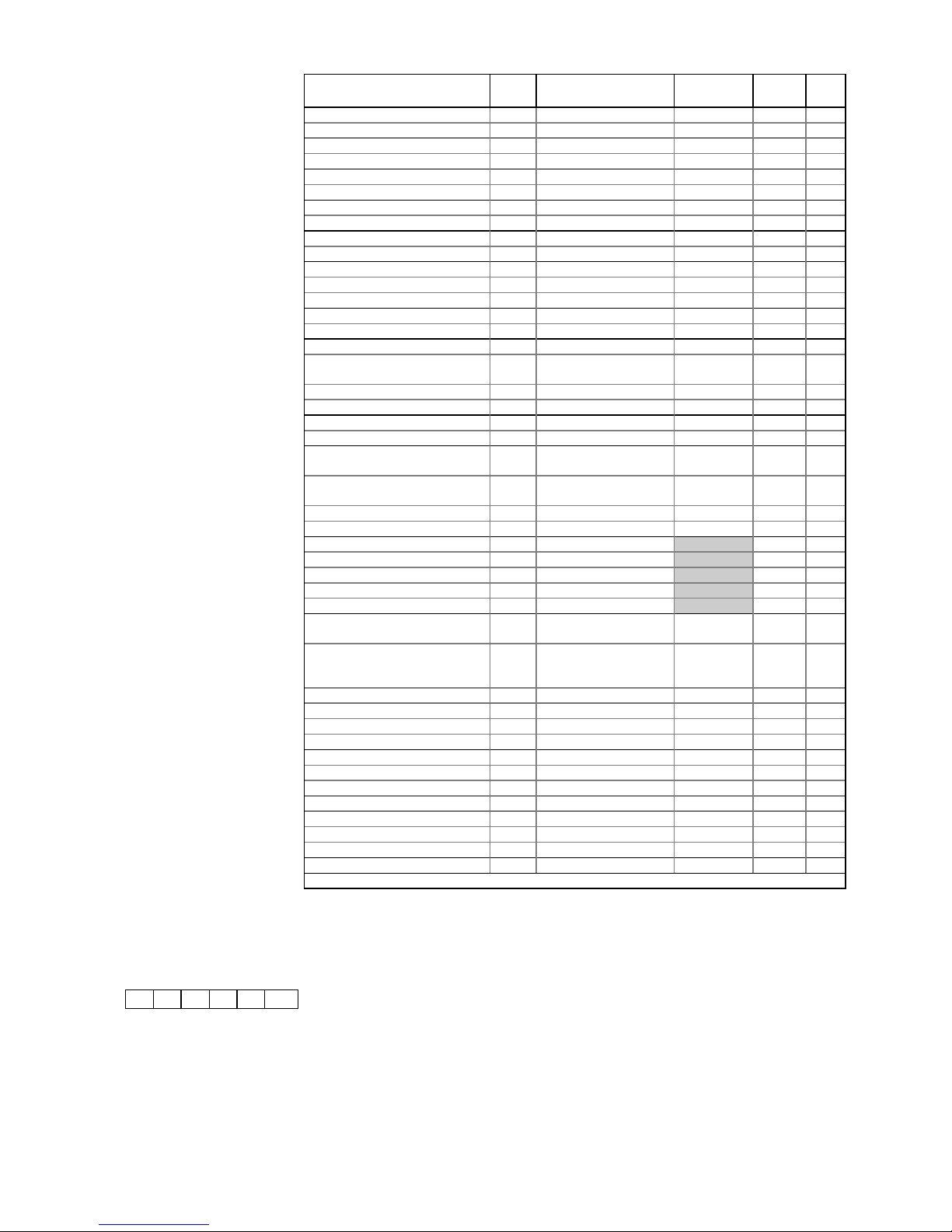
Parameter DIN Range/Units Default
HT(LT)
Dsgn Act.
Cut in Temperature 0 -49 to 30 / °C 0 (-20)
Differential Below 1 0 to 30 / °C 1.5 (2)
Control Weight 2 0 to 100 / % 50
Display Weight 3 0 to 100 / % 50
Section 1: OT Alarm 44 -49 to 60 / °C 5 (-16)
Section 1: UT Alarm 45 -49 to 60 / °C -2 (-25)
Section 2: OT Alarm 47 -49 to 60 / °C 5 (-16)
Section 2: UT Alarm 48 -49 to 60 / °C -2 (-25)
Alarm Delay 17 00:00 to 99:00/Min:Sec 20:00
Latch Alarm: 0=Off ; 1=On 18 0 to 1 0
Defrost Start 4 00:00 to 23:59/Hrs:Mins 01:00
Number of Defrosts per Day 5 0 to 6 6
No Defrost Time 6 0 to 25 / Hrs. 7
Section 1: Defrost Term. Temp. 46 -49 to 60 / °C 10
Section 2: Defrost Term. Temp. 49 -49 to 60 / °C 10
Defrost Minimum Time 7 00:00 to 99:00/Min:Sec 05:00
Defrost Maximum Time 8 00:00 to 99:00/Min:Sec 24:00
(25:00)
Defrost Min. Recovery Time 9 00:00 to 99:00/Min:Sec 20:00
Defrost Max. Recovery Time 10 00:00 to 99:00/Min:Sec 30:00
Drain Down Time 11 00:00 to 20:00/Min:Sec 01:30
Defrost Alarm Temp. 12 -49 to 60 / °C 20
Defrost Type: 0=Elect.;1= (2)Gas
2=(3)Gas
13 0 to 2 0
Defrost Mode: 0=Local ;
1=Remote
14 0 to 1 0
Defrost Hold: 0=Off ; 1=On 15 0 to 1 0
Pulse Defrost: 0=Off ; 1=On 16 0 to 1 0
Hour 19 0 to 23
Minute 20 0 to 59
Day 21 0 to 31
Month 22 0 to 12
Year 23 0 to 99
BST / GMT Select: 0=Auto ;
1=Man.Off ; 2=Man.On
24 0 to 2 0
Lights/Blinds: 0=Local ;
1=Remote ; 2=Man.Off ;
3=Man.On
25 0 to 3 0
Polarity: 0=N/O ; 1=N/C 26 0 to 1 0
Sunday (Blinds) Up / Down 27/28 00:00 to 23:59/Hrs:Mins 08:00/20:00
Monday Up / Down 29/30 00:00 to 23:59/Hrs:Mins 08:00/20:00
Tuesday Up / Down 31/32 00:00 to 23:59/Hrs:Mins 08:00/20:00
Wednesday Up / Down 33/34 00:00 to 23:59/Hrs:Mins 08:00/20:00
Thursday Up / Down 35/36 00:00 to 23:59/Hrs:Mins 08:00/20:00
Friday Up / Down 37/38 00:00 to 23:59/Hrs:Mins 08:00/20:00
Saturday Up / Down 39/40 00:00 to 23:59/Hrs:Mins 08:00/20:00
Gas Alarm: 0=Off ; 1=On 41 0 to 1 0
Minor Leak 42 0 to 3500 / ppm. 50
Major Leak 43 0 to 3500 / ppm. 200
Manual Defrost: 0=Off ; 1=On 99 0 to 1 0
YAD08t / 65EAEE
Display Alarm Messages:
AL Temperature alarm
Ft Probes 1 and 2 are faulty
LA Log probe alarm
Pn probe ‘n’ faulty or not connected
(Where ‘n’ = probe number)
EE EEPROM fault
rr Internal program fault
E1 Plant fault 1
E2 Plant fault 2
ES
Energy-Saving Mode
Store:.............................................
Controller
Name:
Designer:........................................
Date:..............................................
Engineer:........................................
Date:..............................................
Comments:
Universal Controller -
2 Section
ZA-10053-YAD
Issue a : 5/11/96
 Loading...