

Honda Z50R (1988), Z50R (1989), Z50R (1990), Z50R (1993), Z50R (1991) Service Manual
...
BB-99
Z50R
IMPORTANT
SAFm
NOTICE
b.diutes
., stro"g
pouibility
0/
gJf!n
~t'S(JIfQI
;"ju,y
or
(/~Il'"
if
instrJlctions
(In
lIot followt:d.
CAUTION
: Indicates a possibility
oj
pt!FSonol
injury
or
equipment damage
If
instructions are
nOI
followed.
NOTE: Gives helpful info
rmation
.
Detailed descriptions
of
standard
workshop
procedures,
safety
principles
and service ope rat ions are
not
included.
It
is
important
to
note
that
this manual
contains
some
warn
ings and
cautions
against some specific service
methods
which
could cause PERSONAL INJURY
10
service personnel or
cou
ld damage a vehicle
or
render
it
unsafe. Please understand
that
those
warnings
could nOl cover all conceivable
ways
in which service,
whethe
r or
not
reco mmended by Honda
mi
ght
be done or
of
the possi
bly
haz'8rd
ous
consequences
of
each conceivable
way
, nor could Honda investigate all
such
ways. Anyone
using service procedures or tools,
whether
Of
not
recommended by Honda
musr
sarisfy
himself
thoroughly
that
neither personal
safety
nor
vehicle
salety
will
be jeopardized by the service
method
or
tools
selected.
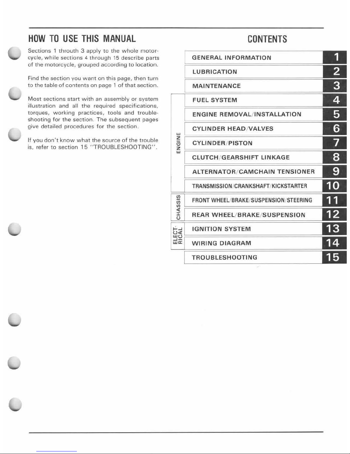
HOW
TO
USE
THIS
MANUAL
Sections 1 throuth 3 apply
to
the
whole
motor
-
cycle,
whi
te sect
ions 4 through
15
describe
parts
of
the
motorcycle
, gr
ouped
according
to
location.
Find the
section
you
want
on
this page ,
then
turn
to
the table
of
contents
on
page 1
of
that
section
.
Most
sections
start
with
an
assembly
or
system
illustration and all
the
required
specifications
.
torques,
working
practices,
tools
and tr
ouble
-
shooting for
the
section.
The
subseque
nt
pages
give detailed pr
ocedures for the
section.
If
you
don't
know
what
the
source
of
the
trouble
is, refer
to
section
15
" TROUBLESHOOTING" ,
CONTENTS
GENERAL
INFORMATION
LUBRICATION
MAINTENANCE
FUEL
SYSTEM
ENGINE
REMOVAL/INSTALLATION
CYLINOER
HEAD/VALVES
~
~================================
==
"
CYLINDER
/PISTON
~
~==========================
======
CLUTCH/GEARSHIFT
LINKAGE
AL
TERNATOR/CAMCHAIN
TENSIONER
TRANSMISSION/CRANKSHAFT/KICKSTARTER
FRONT
WHEEL/BRAKEISUSPENSIONISTEERING
REAR
WHEEL/BRAKE/SUSPENSION
t;;i
IGNITION
SYSTEM
w"
~-
wa:
WIRING
DIAGRAM
TROUBLESHOOTING
1.
GENERAL
INFORMATION
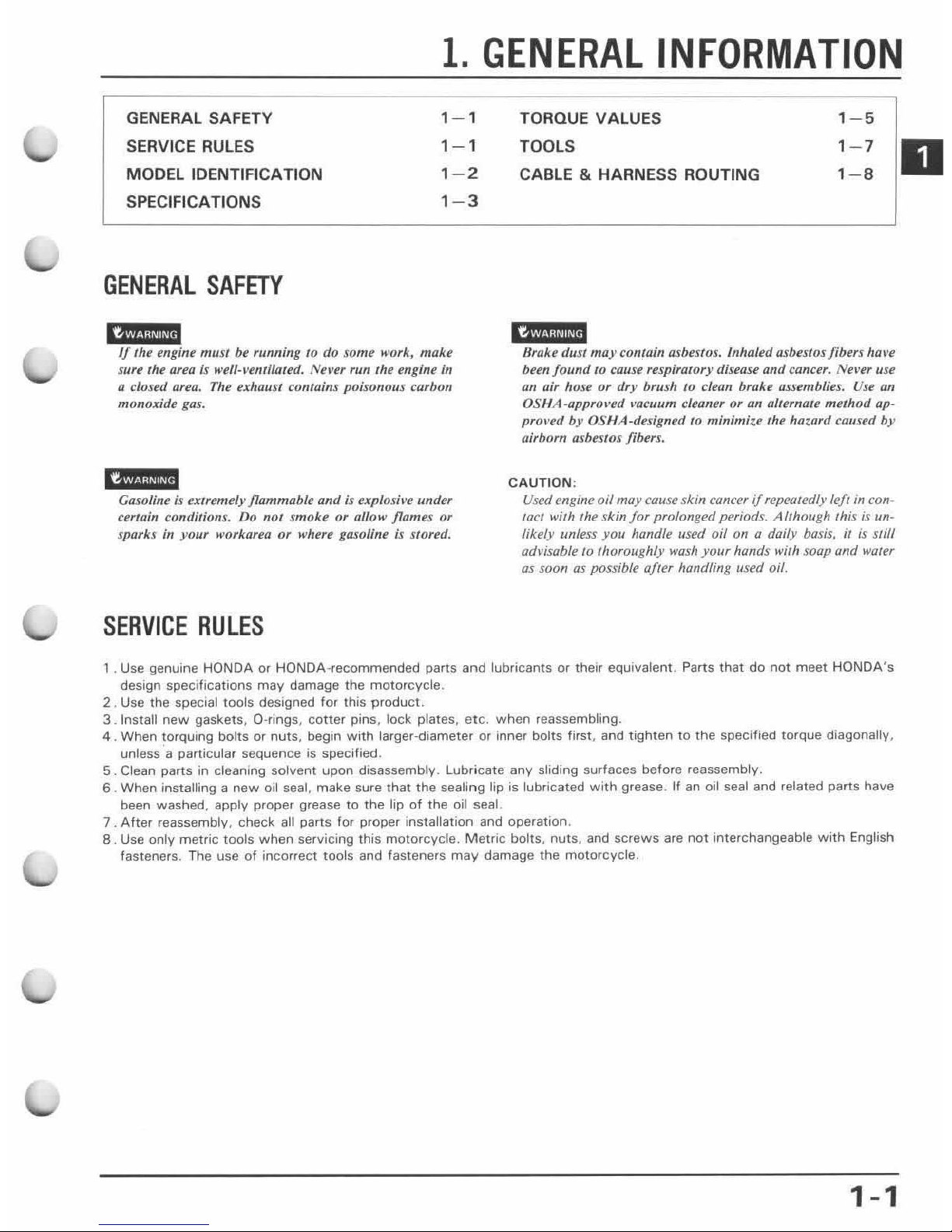
GENERAL SAFETY
SERVICE
RULE
S
MODEL IDENTIFICATION
SPECIFICATIONS
GENERAL
SAFETY
1-
1
1- 1
1
-2
1- 3
must be running
to
do some work, malce
Slife the area is well- I'enrilated.
Nea'er
run the engine in
Q closed
area,
The exhaust contains poisonous carbon
monoxide gas.
i~
Gasoline is extremely
flammable
and
is t!xplosil't! Ilnder
certain conditions. Do not
smoke
or allow flames or
sparks
in
your workarea or where gasoline
is
srored,
SERVICE
RULES
TORQUE VALUES
TOOLS
CABLE & HARNESS ROUTING
1-5
1- 7
1-B
H",k" d'
u"
"",,,'0",,,1.
",b"",,,.
Inhaled asbestos fibers
hOI'1!
been
found
10
calise respiratory disease
and
canUf.
Nel'er use
all
air hose
or
dry brush
to
clean broke assemblies.
Use
an
OSIIA-appro,'ed ,'ocullm cleaner or un alternate ml!lhod up-
prol
-ed
by
OSHA-designed
to
minimize the hazard caused
by
airborn asbt!slOs fibers.
CAUTION:
Used engine
oil
may
cause skin cancer
if
repealedly left
in
con-
tact
with the skin
for
prolonged periods. Although this is un-
likely unless
yOIl
handle used oil on a doily basis,
il
is
slill
advisable
10
Ihoroughly
wash
your
hands wilh soap and waler
as soon as possible afler handling used oil.
1. Use genuine HONDA Of HONDA-recommended parts and lubricants or their equivalent. Parts
that
do
not
meet
HONDA's
design specifications may damage the motorcycle.
2 . Use the
special tools designed for this
product.
3 . Install
new
gaskets,
a-rings, cotter
pins, lock plates,
etc.
when
reassembling.
4 . When torquing
bolts
or nuts, begin
with
larger-diameter or inner bolts first, and tighten to
the
specified torque diagonally,
unless
a particular sequence is specified .
5 .
Clean parts in cleaning solvent
upon
disassembly. Lubricate any sliding surfaces before reassembly.
6 . When
installing a
new
oil seal, make sure
that
the
sealing lip is lubricated
with
grease. If
an
oil seal and related parts have
been washed,
apply proper grease
to
the lip
of
the oil seal
7 .
After
reassembly, check all parts for proper installation and operation.
8 . Use
only metric tools
when
servicing this motorcycle.
Metri
c bolts, nuts, and screws are
not
interchangeable
with
English
fasteners. The use
of
incorrect tools and fasteners
may
damage the motorcycle.
1-1
D

GENERAL
INFORMATION
MODEL
IDENTIFICATION
The carburetor identification
number
is
on
the
right side
of
the carburetor
body
.
The color
label is attached on the left side
of
the
frame above
the
front
of
the chain guard.
1-2
5S
The
frame serial n
umber
is stamped
on
the left
side
of
the
steering head.
The engine
se
rial
numbe
r is stamped on
the
lower
left
side
of
the
crankcase.
GENERAL
INFORMATION
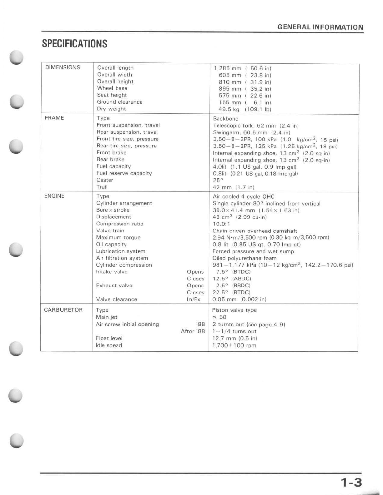
SPECIFICATIONS
DIMENSIONS
Overall
length
1
,285
mm
I
50.6
in)
Overall
width
605
mm
I
23.8
in)
Overall
height
810
mm
I
31.9
in)
Wheel base
895
mm
I
35.2
in)
Seat
height
575
mm
I
22.6
in)
Ground
clearance
155
mm
I
6.1
in)
Ory
weight
49.5
kg
(109.1
Ib)
FRAME
Type
Backbone
Front
suspension,
travel
Telescopic fork,
62
mm
(2.4
inl
Rear suspension, travel
Swingarm,
60.5
mm
12.4
in)
Front
tire
size,
pressure
3.50-S-2PR,
lOa
kPa
(1.0
kg f
cm
2
,
, 5 psi)
Rear
tire
size, pressure
3.50-S-2PR.
125
kPa
11.25
kg/cm
2
,
18
psi)
Front
brake
Internal
expanding
shoe,
13
cm
2
(2
.0
SQ-inj
Rear brake
Internal
expanding
shoe,
13
cm
2
(2.0
sq-in)
Fuel
capacity
4.0lit
(1.1
US
gal,
0.9
Imp
gal)
Fuel reserve
capacity
a.Stit (0.21 US gal,
0.18
Imp
gal)
Caster
25'
Trail
42
mm
(1.7
in)
ENGINE
Type
Air cooled
4-cy
cle OHC
Cylinder
arrangement
Single cylinder
80"
inclined
from
vertical
Bore x stroke
39.0x
41.4
mm
(1.
S4xl.63
in)
Displacement
49
cm
3
12.99 cu-in)
Compression ratio
10.0:1
Valve train
Chain
driven overhead
camshaft
Maximum
torque
2.
94
N-m/3,SOO
rpm
(0.30
kg-m
/ 3,
SOO
rpm)
Oil capacity
0.8
lit
(0.8
5 US
qt,
0.70
Imp
qt)
lubrication
system
Forced pressure and
wet
sump
Air
filtration
system
Oiled polyurethane
foam
Cylinder compression
981-1,177
kPa
(10-12 kg/
cm
2
,
142.2-
170,6
psi)
Intake valve
Opens 7.S
o
(BTDC)
Closes
12.5
0
(ABO
C)
Exhaust valve
Opens 2.
5"
(BBDCI
Closes
22.5"
(B
TDC )
Valve clearance
In
/Ex
0.05
mm
(0.002
in)
CARBURETOR Type Piston valve
type
Main
jet
::::
58
Air
screw
initial
opening
'88
2
turnts
out
(see
page 4-9)
Aher
'88
1- 1 / 4
turns
out
Float level , 2.7
mm
(0.5 in)
Idle spead
1JOO±100
rpm
1-3
GENERAL
INFORMATION
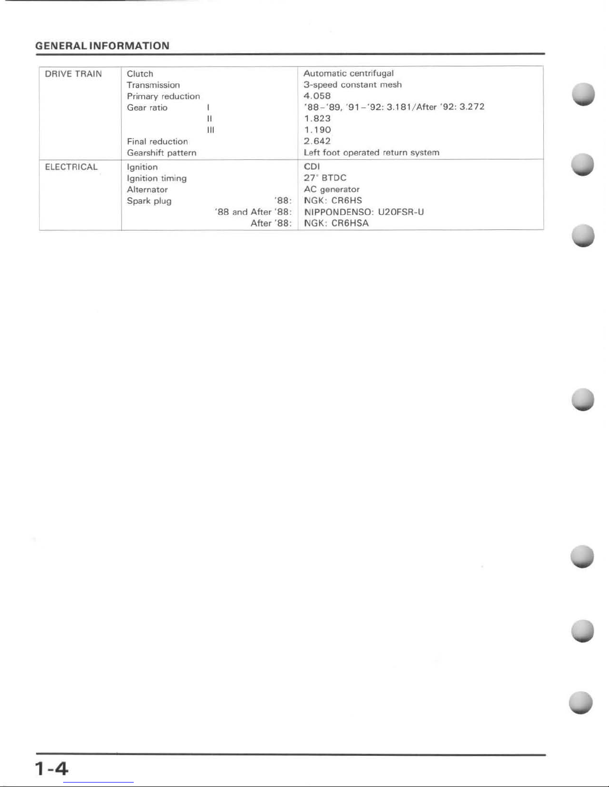
DRIVE TRAIN
Clutch
Automatic
centrifugal
Transmission
3~speed
constant mesh
Pr
imary reduction
4.
058
Gear ratio I
'S8-'89, '91-'92: 3.181
/After '92:
3.272
II
1.
823
III
1.
190
Final reduction 2 .
642
Gearshift
pattern
left
foot
operated
return
system
ELECTRICAL
Ignition
CDI
Ignition
timing
27
' BTDC
Alternator
AC generator
Spark plug
'S8:
NGK: CA6HS
'
88
and
After 'S8
:
NIPPONDENSO :
U20FSR·U
After '88:
NGK: CA6HSA
1-4
GENERAL
INFORMATION
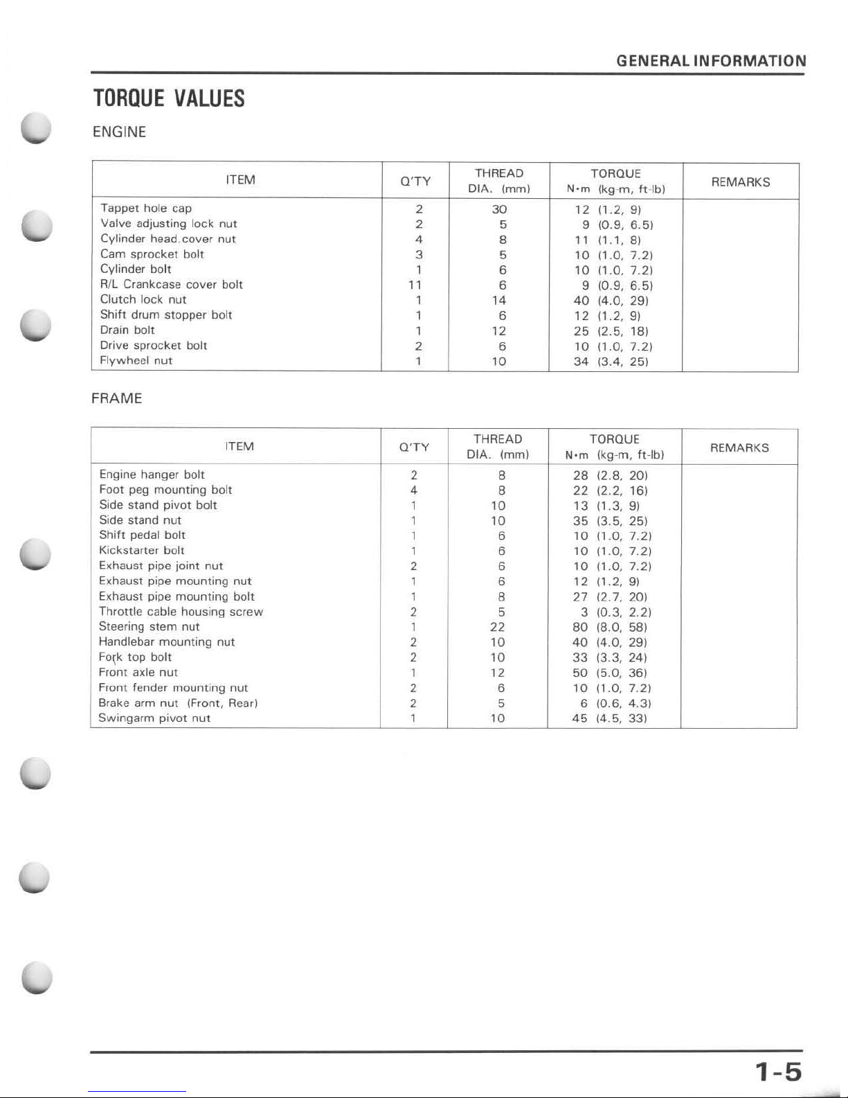
TORQUE
VALUES
ENG
INE
ITEM
Q'TY
THREAD
TORQUE
REMARKS
OIA.
(mm)
N'm
(kg-m, ft
·lb)
Tappet hole cap
2
30
12 (1.2, 9)
Valve adjusting lock
nut
2 5 9 (0.9 , 6.5)
Cylinder head. cover nut
4
8
11
(1.1,
8)
Cam sprocket bolt
3 5
10
(1.0,7.2)
Cylinder bolt
1 6
10
(1.0, 7.
2)
R/l Crankcase
cover
boh
11
6
9
(0.9,6.5)
Clutch
lock
nut
1
14
40
(4.0,29)
Shift drum stopper
bolt
1
6
12
/1.2
, 9)
Drain bolt
1 12
25
12.5,
lS)
Drive sprocket bolt
2 6
10
(1.0,
7.21
Flywheel nut
1
10
34
(3.4, 25)
FRAME
ITEM
Q'TY
THREAD
TORQUE
REMARKS
DIA.
(mm)
N'm
Ikg-m
, ft-lbJ
Engine hanger bolt
2
8
28
(2.8, 20)
Foot peg
mounting
bolt
4
8
22
(2.2,
16)
Side stand
pivot
bolt
1 10
13
(1,3
, 9)
Side stand
nut
1
10
35
(3.5, 25)
Shift pedal bolt
1
6
10
(1.0,
7.2)
Kickstarter bolt
1
6
10
11,0, 7.
21
Exhaust
pipe
joint
nut
2
6
10
11.0,
7.21
Exhaust
pipe
mounting
nut
1 6 12
(1.2, 9)
Exhaust
pipe
mounting
bolt 1
8 27
(2.7,20)
Throttle
cable
housing
SCrew
2 5 3
(0.3,2.2)
Steering
stem
nut
1 22
80
(8.0, 58)
Handlebar
mounting
nut
2
10
40
(4.0, 29)
Fo~k
top bolt
2
10
33
(3.3
, 24)
Front
axle
nut
1 12
50
(5.0
, 36)
Front fender
mounting
nut
2 6
10
(1.0
, 7.2)
Br
ake
arm
nut
(Front, Read
2 5 6
(0.6,
4.3)
Swingarm
pivot
nut
1
10
45
(4,5, 33)
1-5
GENERAL
INFORMATION
ITEM
O'TY
THREAD
TORQUE
REMARKS
DIA.
(mm
)
Nom
(kg-rn. ft-Ibl
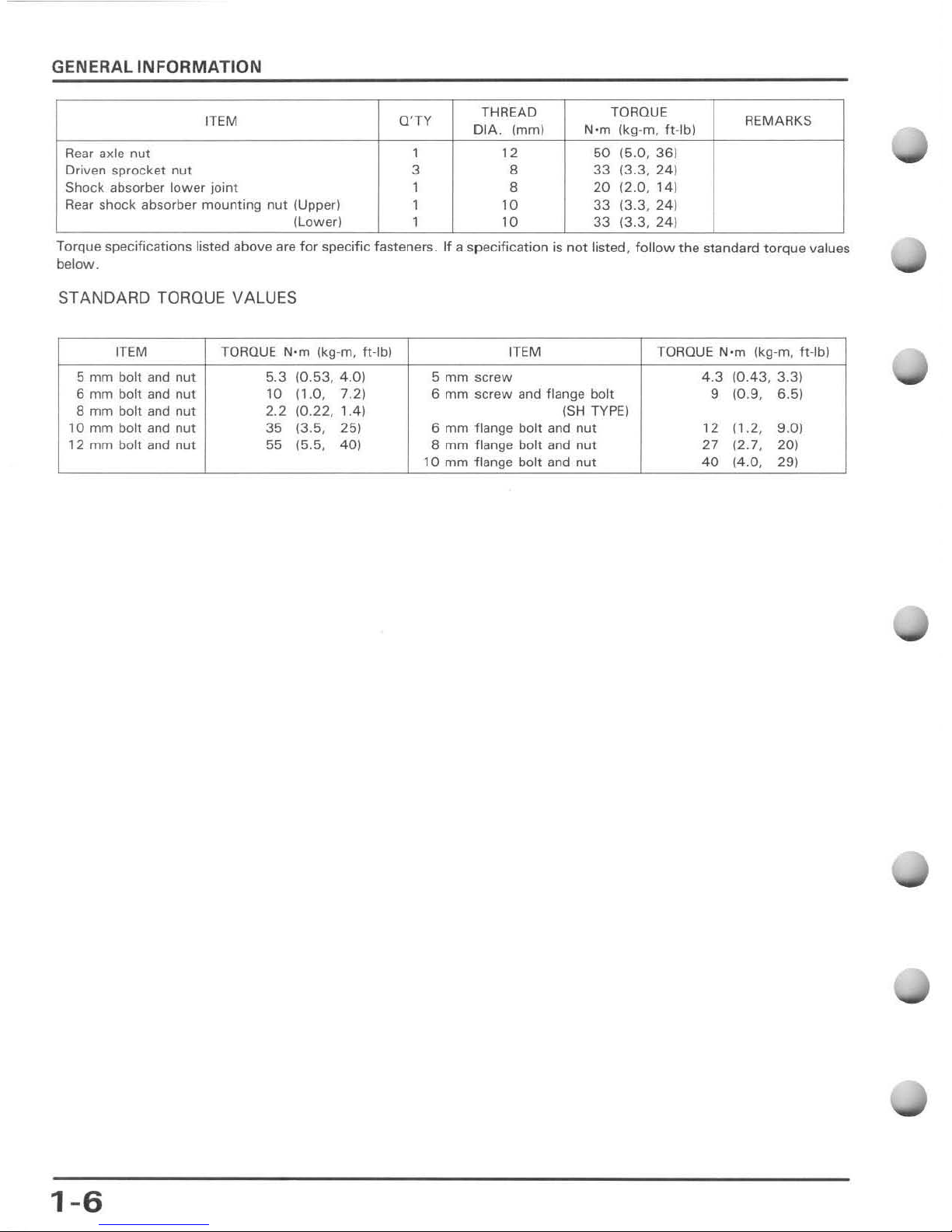
Rear axle
nut
1
12
50
(5.0,36)
Driven
sprocket
nut
3 8
33
(3.3,24)
Shock absorber
lower
joint
1 8
20
(2.0,
14)
Rear shock absorber
mounting
nut
(Upper)
1
10
33
(3.3
, 24)
(lower)
1 10
33
(3.3,24)
Torque specifications listed above are
for
specific fasteners.
If
a specification is
not
listed,
follow
the standard torque values
below.
STANDARD TORQUE VALUES
ITEM
TORQUE
Nom
(kg-rn. ft-Ib)
ITEM
TORQUE
Nom
(kg-rn, ft-Ib)
5
mm
bolt
and
nut
5.3
(0.53,
4.01
5
mm
screw
4.3
(0.43,
3.3)
6 mm bolt and nut
10
n.D, 7.
2)
6 mm
screw
and flange
bolt
9
(0.9,
6.5)
B mm bolt and nut 2.2
(0.22, 1.41
ISH TYPE)
, a mm boh and nut
35
(3.5,
251
6 mm flange
bolt
and
nut
12
11
.2,
9.0)
12
mm
boh
and
nut 55
(5.5,
401
8
mm
flange
bolt
and
nut
27
(2.7,
201
10
mm
flange
bolt
and
nut
40
j4.0,
29)
1-6
GENERAL
INFORMATION
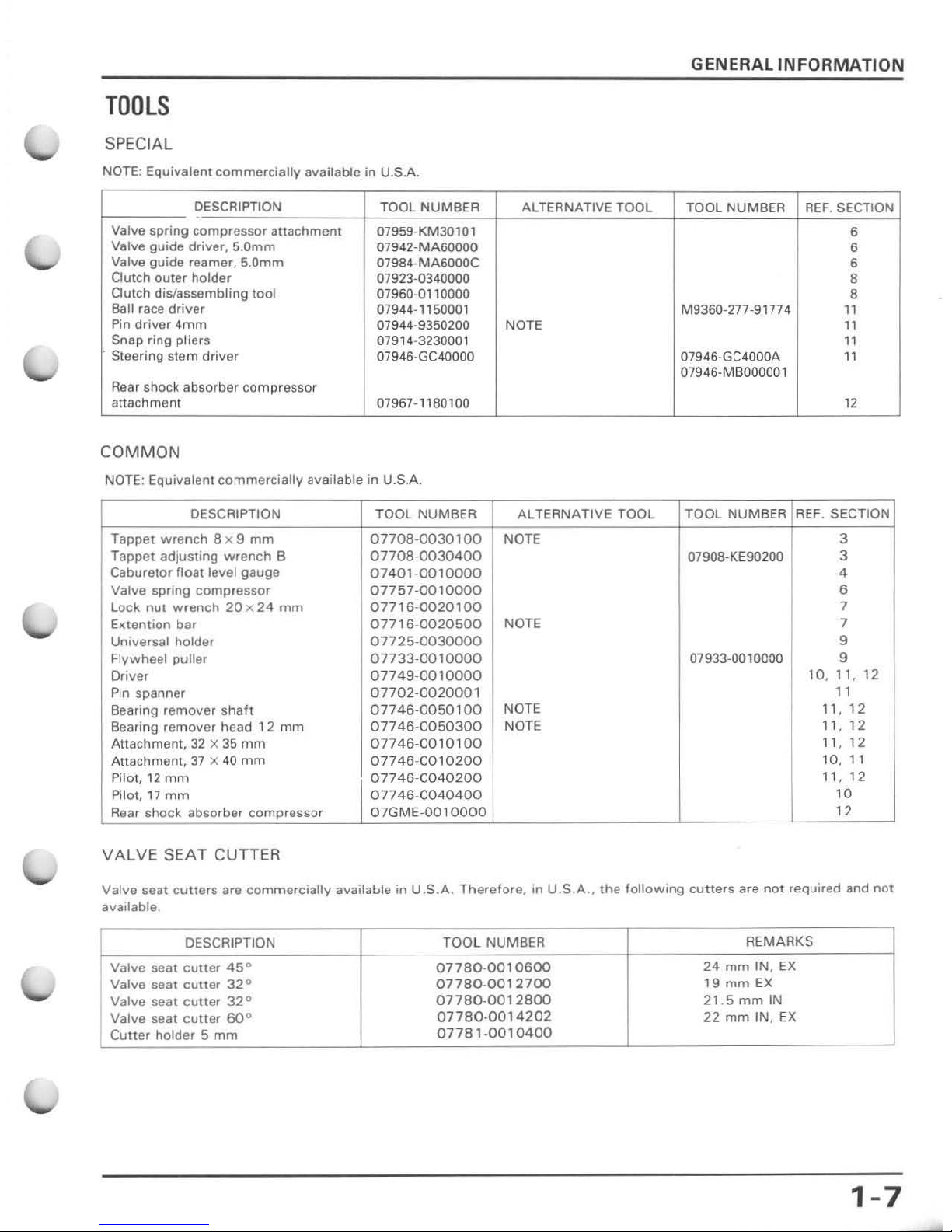
TOOLS
SPECIAL
NOTE: Equivalent
commerciallv
available
in
U.S.A.
DESCRIPTION
TOOL
NUMBER
ALTERNATIVE TOOL
TOOL NUMBER
REF
. SECTION
"
Valve spring
compressor
attachment
07959·KM30101
6
Valve guide driver, S.Omm
07942·MA60000
6
Valve guide reamer, S.Omrn
07984·MA6000C
6
Clutch
outer
holder
07923-0340000
•
Clutch dis/assembling tool
07960-0110000
•
Ball race
driver
07944-"50001
M9360·277-91774
"
Pin
driver
4mm
07944-9350200
NOTE
"
Snap ring pliers 07914-3230001
"
. Steering
stem
driver
07946·GC40000 07946·GC4000A
"
07946·MBOOOOOl
Rear shock
absorber
compressor
attachment 07967-1180100 12
COMMON
NOTE: Equivalent
commercially
available
in
U.S.A.
DESCRIPTION TOOL NUMBER ALTERNATIVE TOOL
TOOL
NUMBER
REF.
SECTION
Tappet
wrench
8 x 9
mm
07708-0030100
NOTE 3
Tappet adjusting
wrench
B
07708-0030400
0790B-KE90200
3
Caburetor fl(}at level gauge
07401·0010000
4
Valve spring compressor
07757·0010000
6
lock
nut
wrench 20x
24
mm
07716·0020100
7
Extention bar
07716·0020500
NOTE
7
Universal holder
07725-0030000
9
Flywheel puller
07733-0010000
07933~OO10000
9
Driver
07749-0010000
10, 11, 12
Pin
spanner
07702-0020001
11
Bearing remover
shaft
07746-0050100
NOTE
11,
12
Bearing remover head
12
mm
07746·0050300
NOTE
11,
12
Attachment,32 x 35
mm
07746-0010100
11 , 12
Attachment,
37 x 40
mm
07746-0010200
10,
11
Pilot,
12
mm
07746-0040200
11,
12
Pilot,
17
mm
07746-0040400
10
Rear shock absorber compressor
07GME-0010000
12
VALVE SEAT CUTTER
Valve seat
cutters
are
commercially
availaLle in U.S .A .
Therefore
, in U.S.A. ,
the
following
cutters
are
not
required and
not
available.
DESCRIPTION
TOOL
NUMBER
REMARKS
Valve seat
cUller 45°
07780-0010600
24
mm
IN, EX
Valve seat
cutter 32°
07780·0012700
19
mm
EX
Valve seat
cUller 32°
07780-0012800
21.5
mm
IN
Valve
seat
cutter 60°
07780·0014202
22
mm
IN,
EX
Cutter
holder 5
mm
07781·0010400
1-7
GENERAL INFORMATION
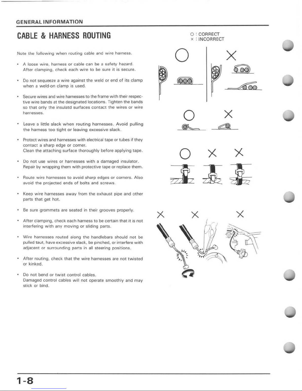
CABLE & HARNESS
ROUTING
Note the following
when
routing cable and wire harness.
A loose wire, harness
or
cable can
be
a safety hazard.
After
clamping. check each wire to be sure
it
is secure.
00
not sequeeze a
wire
against the weld or end
of
its clamp
when
a weld-on clamp is used.
Secure wires and wire harnesses
to
the
frame
with
their respec·
tive wire bands at the designated locations. Tighten the bands
so
that
only
the
insulatd surfaces
contact
the
wires
or wire
harnesses.
Leave
a little slack when routing harn
esses.
Avoid pulling
the
harness t
oo
tight
or
leaving excessive slack.
Protect wires and
harnesses
with
electrical tape or tubes
if
they
contact
a sharp edge or corner.
Clean the attaching surface thoroughly before applying tape.
Do
not
use wires
or
harnesses with
a damaged insulator.
Repair by wrapping them
with
protective tape
or
replace them.
Route wire harnesses to avoid sharp edges
or
corners. Also
avoid the projected ends
of
bolts and
screws
.
Keep wire harnesses
away
from the e)(haust pipe and
other
parts that get hot.
Be
sure gro
mmets
are seated in their grooves properly.
Aher
clamping. check each harness
to
be certain
that
it
is
not
interfering
with
any
moving
or
sliding parts .
Wire harnesses routed along the handlebars should not
be
pulled taut, have excessive slack, be pinched,
or
interfere
with
adjacent or surrounding parts in all steering positions.
After
routing, check that the
wire
harnesses are not
twisted
or
kinked.
Do not bend or
twist
control cables.
Damaged
control
cables will
not
operate
smoothly
and
may
stick
or
bind.
1-8
x
0:
CORRECT
x : INCORRECT
o
o
~
X
Q
X
d
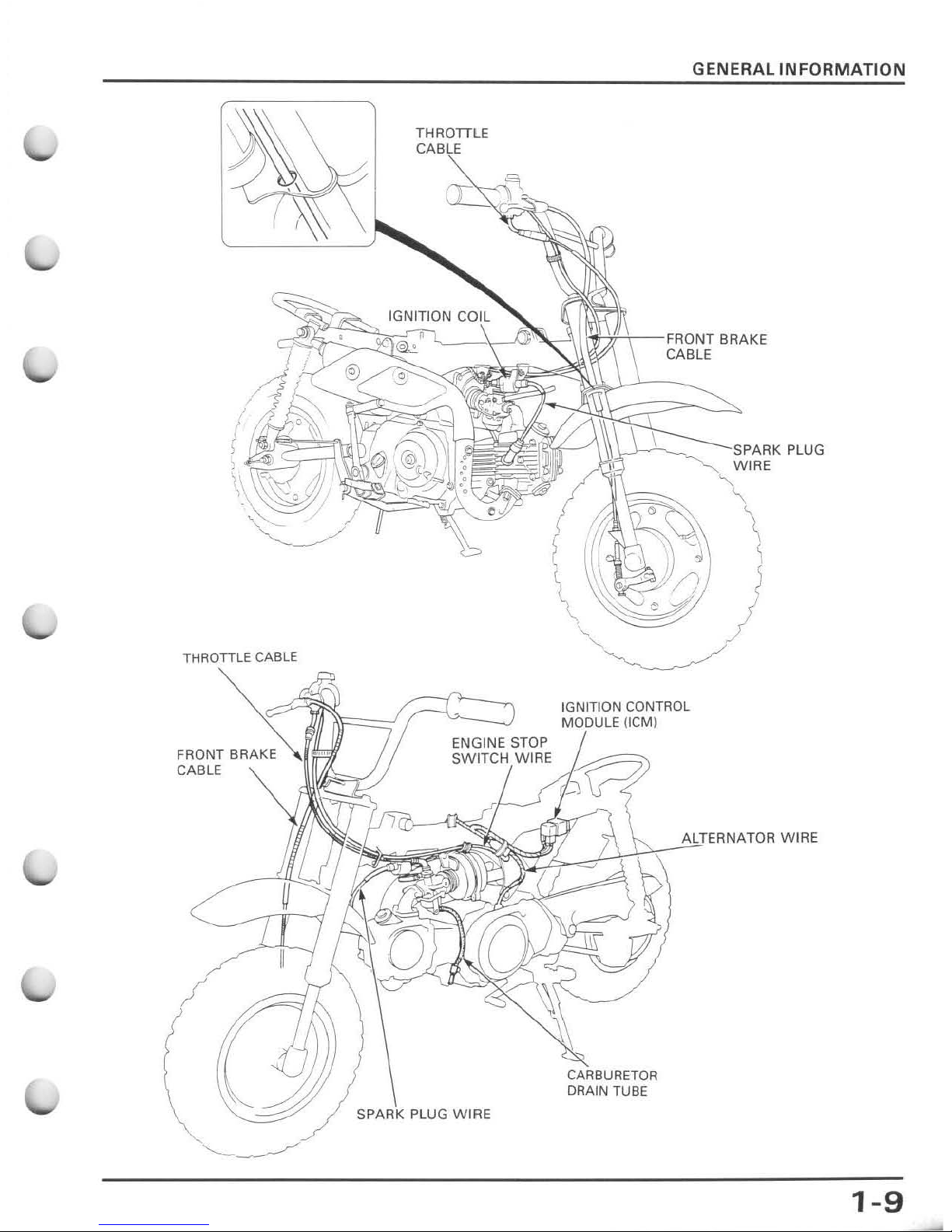
THROTTLE
/
SPARK PLUG W I
RE
GENERAL
INFORMATION
~-\-
-FR()NT
BRAKE
CABLE
'-'---
_
-~-
SF'AF"
PLUG
WIRE
ALTERNATOR W I
RE
~
Prt\
~
C
ARBURETOR
DRAIN TUBE
1-9
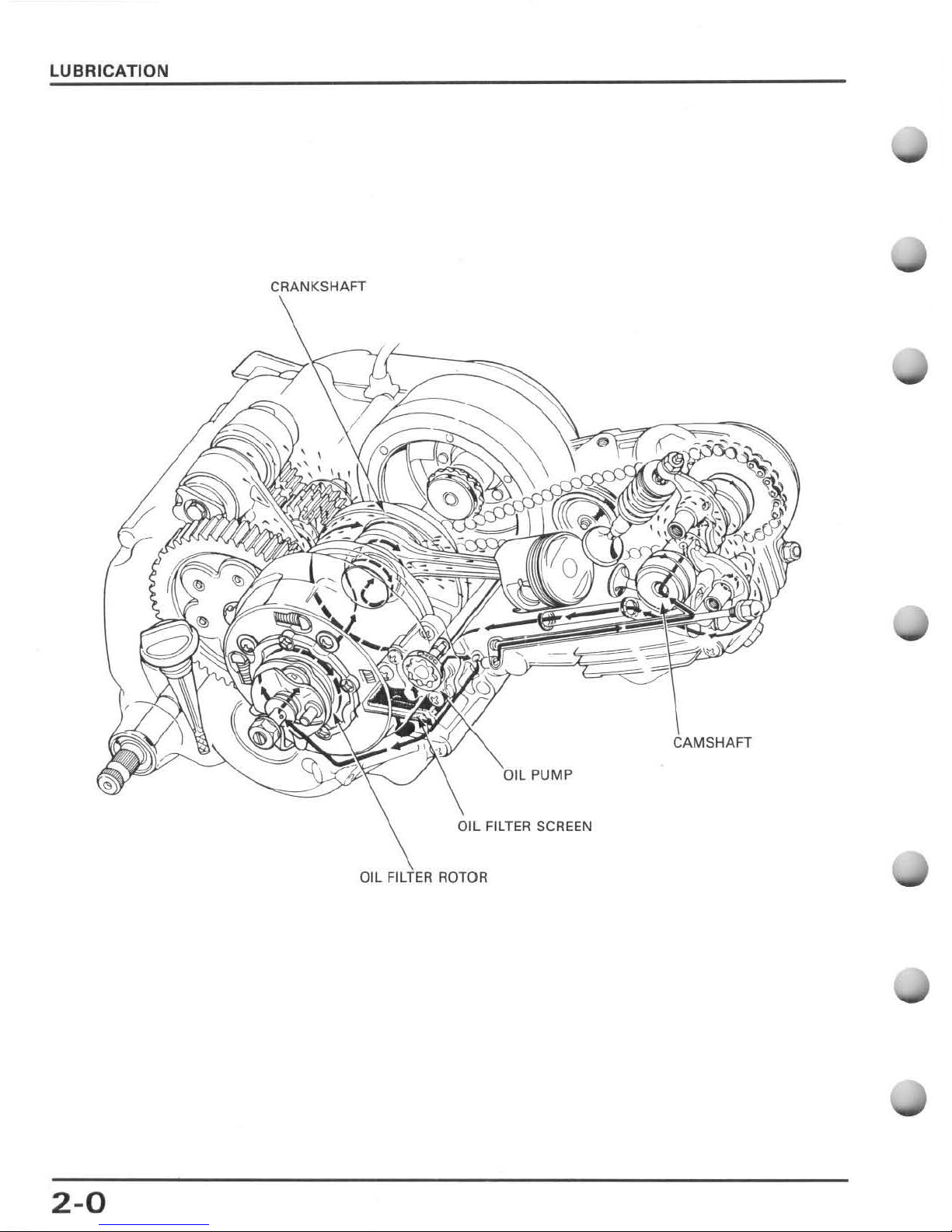
LUBRICATION
I PUMP
OIL ROTOR
2-0
2.
LUBRICATION
SERVICE
INFORMATION
TROUBLESHOOTING
ENGINE
OIL
LEVEL
CHECK
ENGINE
OIL
CHANGE
2-1
2-1
2
-2
2-2
2-2
OIL
PUMP
REMOVAL/DISASSEMBLY
2-3
OIL
PUMP
INSPECTION
2-3
OIL
FILTER ROTOR
AND
SCREEN
SERVICE
INFORMATION
G
ENER
AL
CAUT
ION
OIL
PUMP
ASSEMBLY
OIL
PUMP
INSTALLATION
LUBLICATION
POINTS
2-4
2-4
2-5
Used engine oil
lIIay
ca
use
skill
cancn
if
repeatedly left
{II
contact
wilh
the skin Jar prolonged periods. Although this is IInlikely
IInlns
you
handle used oil
on
a daily
basis, il
is
Sli/!
ad~'isab{e
/0
(haroughly
wash
your hands
with
soap
and
water as
Sooll
as
pillsible a/ler handing used oil
• This section describes
checking
the engine oil level,
changing
engine oil, cleaning the oil
filter
rot
or
and screen, oil
pump
maintenance
and
service, and lubrication.
• The oil
pump
can
be
disassembled
with
the engine in the frame.
SPEC
IFI
CATIONS
Oil capacity
Recommended engine oil
0.8 lit
(0.85
US
qt
, 0.70 Imp qt)
81
disassemblv
a.
Slit
(0.63
US
qt
, O.
53Impqt
) at aherdraining
Use
Honda GN4 4-Stroke Oil,
SAE
10W-40
Of'
equivalent.
API
service classificatIOn:
SF
or
SG
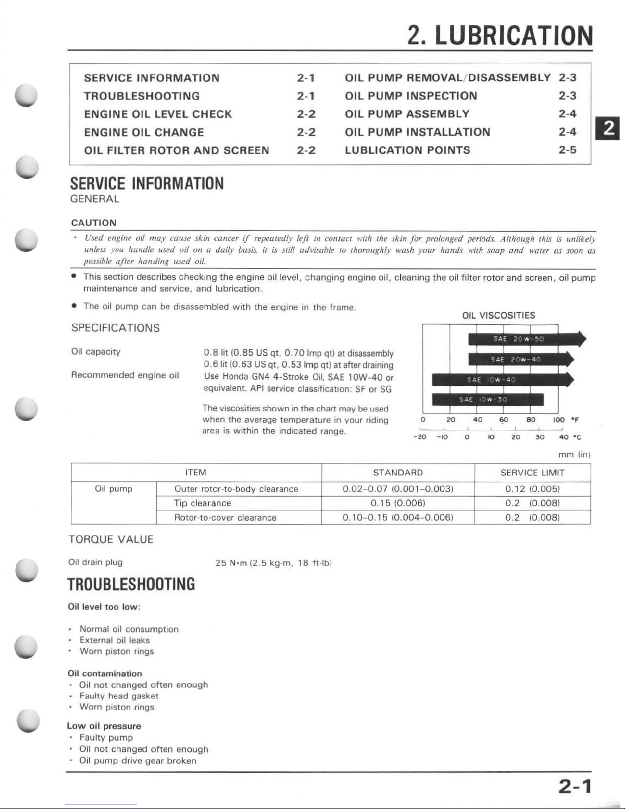
OIL VISCOSITIES
The viscosities shown
in
the chart may be used
when the average temperature in your
riding
area is Within the indicated range.
-20
-10
a
20
30
4O'C
ITEM
Oil
pump
Ouler rotOHo-bodV clearance
Tip
clearance
Rotor-
la
-cover clearance
TORQUE VALUE
O
il
dratn plug
TROUBLESHOOTING
Oil level
too
low
:
Normal oil consumption
External oil leaks
Worn piston rings
Oil contamination
011
not
changed
often
enough
• Faulty head gasket
• Worn piston
ling
s
l
ow
oil
pressure
Faulty
pump
Oil
not
changed
often
enough
Oil
pump
drive
gear
broken
25
N'm
(2.5
kg-m.
18
ft-lbJ
mm
hnl
STANDARD
SERVI
CE
LIMIT
0.02-
0.07
(0.001-0.003)
0.12
10.005)
0.
15
(0.006)
0.2
(0.008)
0_ 1 0-
0.15
(O.004 0 .
006)
0.2
(0.008)
2-1
LUBRICATION
ENGINE
OIL
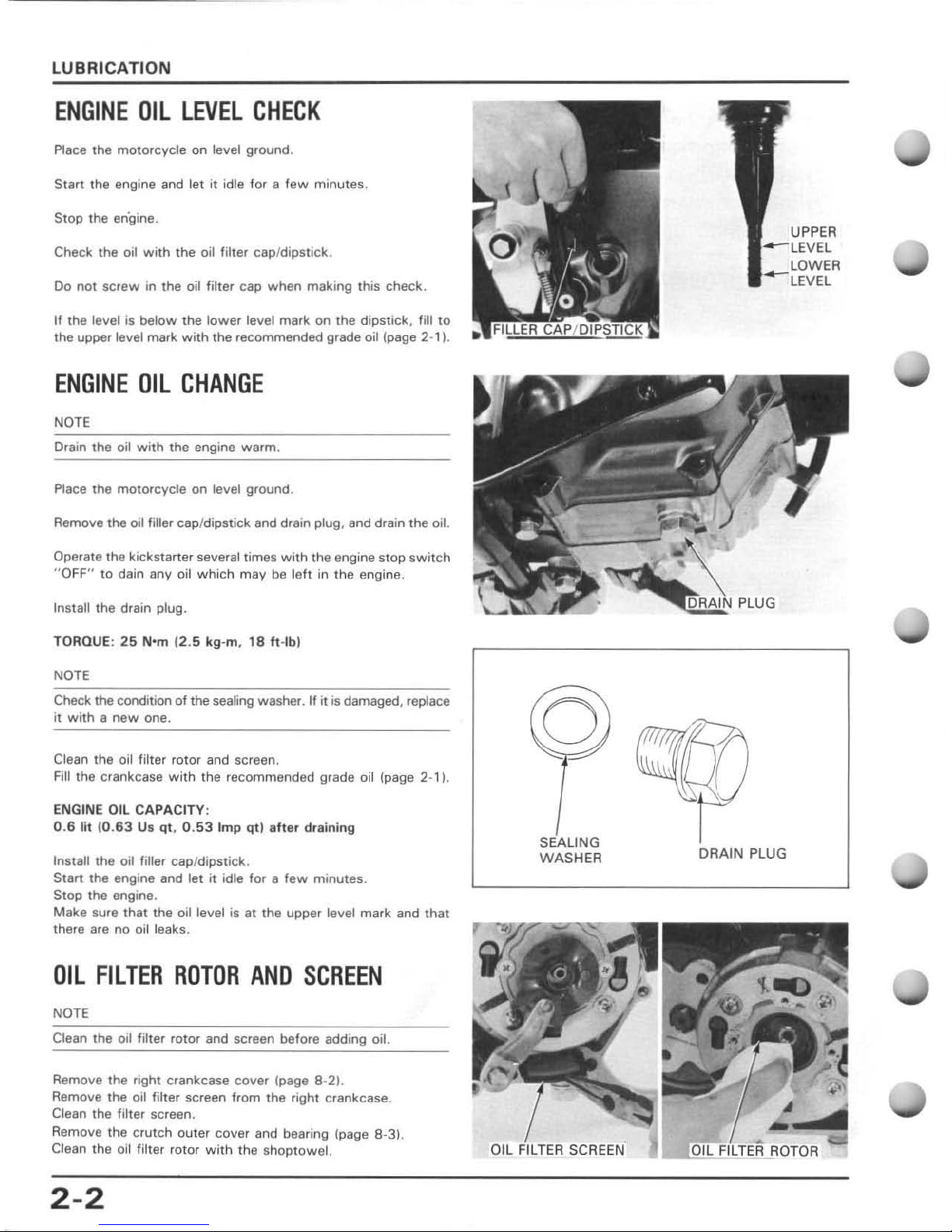
LEVEL
CHECK
Place the
moto
rcycle
on
le
....
el ground.
Start the engine and tet
it
idle for a
few
minutes.
Stop
the engine.
Check the oil
with
the oil filter cap/dipstick .
Do
not
screw
in the oil filter cap when making this check.
If the level is
below
the
lower
level mark on
the
dipstick ,
fiU
to
the upper level mark
with
the recommended grade oil (page 2-1).
ENGINE
OIL
CHANGE
NOTE
Drain the oil
with
the
engine warm.
Place the
motorcycle
on
level ground .
Remove the oil filler cap/
dipstick
and drain plug, and drain the oil.
Operate the kickstarter several times
with
the engine stop
switch
"
OFF
" to dain any oil which may
be
left
in
the
engine.
Install the drain plug.
TORQUE:
25
N'm
{2.S kg-m.
18
h -
Ibl
NOTE
Check the condition
of
the sealing washer. If
it
is damaged, replace
it
with a new
one.
Clean
the
oil filter rotor and screen.
Fill the crankc ase
with
the recommended grade oil (page 2-1).
ENGINE
Oil
CAPACITY:
0.6
lit 10.
63
Us qt, 0.
53
Imp
qt) after
draining
Install the oil filler cap/dipstick .
Start the engine and let
it
idle for a
few
minutes.
Stop
the
engine.
Make sure
that
the oil level
is
at the upper level
mark
and
that
there are
no
oil leaks.
OIL
FILTER
ROTOR
ANO
SCREEN
NOTE
Clean the oil filter rotor and screen before adding oil.
Remove
the
right crankcase cover
~page
8-21.
Remove the oil filter screen from the right crankcase.
Clean the filter screen.
Remove the crutch outer cover and bearing (page 8-3).
Clean the oil filter rotor
with
the shoptowel.
2-2
SEALING
WASHER
SCREEN
"
DRAIN
PLUG
OIL
PUMP
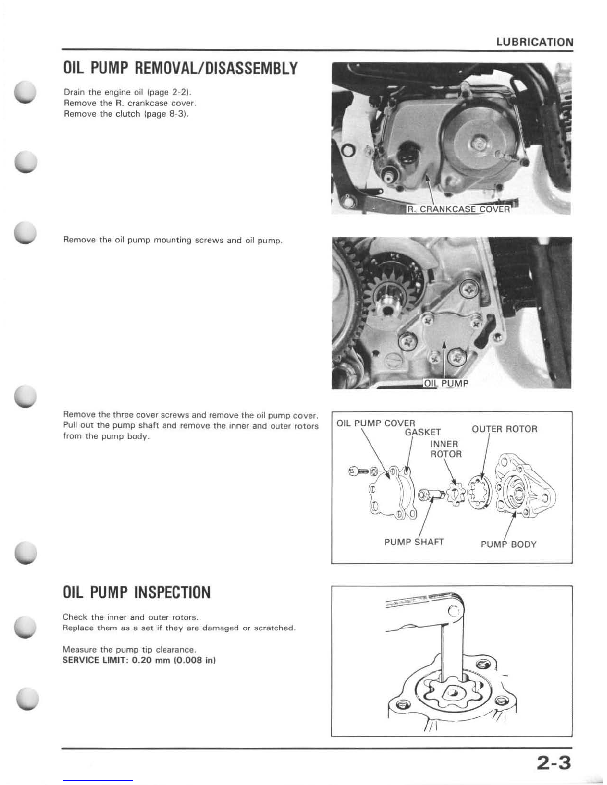
REMOVAL/DISASSEMBLY
Drain the engine oil (page 2-2
).
Remove
the
R.
crankcase cover.
Remove the
clutch
(page 8-3).
Remove the
oil
pump
mounting screws
and oil pump.
Remove the three cover
screws
and remove the oil
pump
cover.
Pull
out
the
pump
shaft and remove the inner and
outer
rotors
from the
pump
bodV.
OIL
PUMP
INSPECTION
Check the inner and
outer
rotor
s.
Replace
them
as a set
jf they are damaged
or
scratched .
Measure the
pump tip
clearance.
SERVICE
LIMIT: 0.20
mm
(0.0
08
in(
LUBRICATION
OUTER ROTOR
PUMP BODY
c
2-3
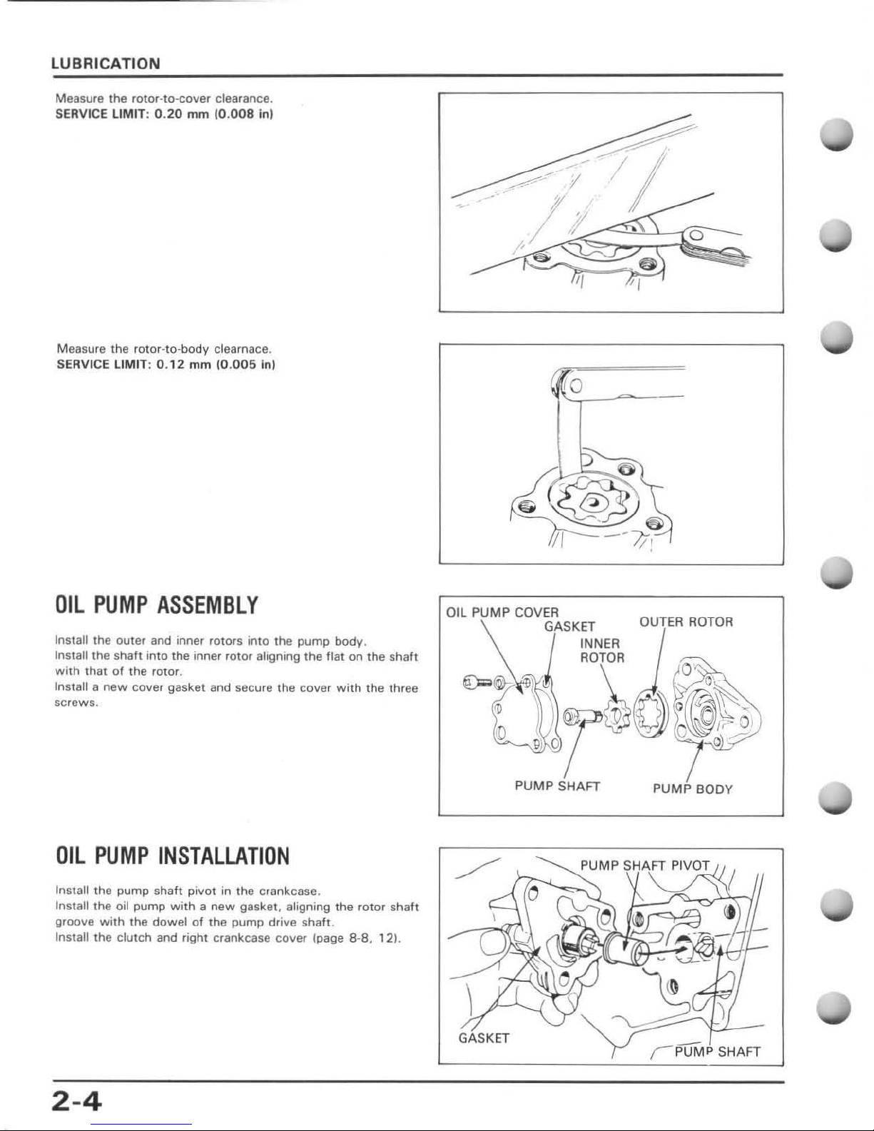
LUBRICATION
Measure the rotor-to-cover clearance.
SERVICE LIMIT: 0.
20
mm 10.
008
inl
Measure
the
rotor-ta-body clearnace.
SE
RVi
Ce
LIMIT: 0.12
mm
10.005
in)
OIL
PUMP
ASSEMBLY
Install the outer and inner rotors inlO the
pump
body
.
Install the shah into the inner rotor aligning
the
flat
on
the
shah
with thai
01
the
rotor.
In
stall a
new
cover gasket and secure the cover
with
the
three
screws.
OIL
PUMP
INSTALLATION
Install the pump shaft
pivot
in the cran kcase.
Install the oil pump
with a new
gasket, aligning
the
rotor
shalt
groove
with
the
dowel
of
the
pump
drive sha
ft.
Install the
clutch
and fight crankcase
cover
Ipage 8·8.
'21.
2-4
10
Oi
l PUMP COV
ER
~
GASKET
INNER
AOTOR
OUTER
ROTOR
PUMP SHAFT
PUMP BODY
\
GASKET
{ PuMP
SHAFT
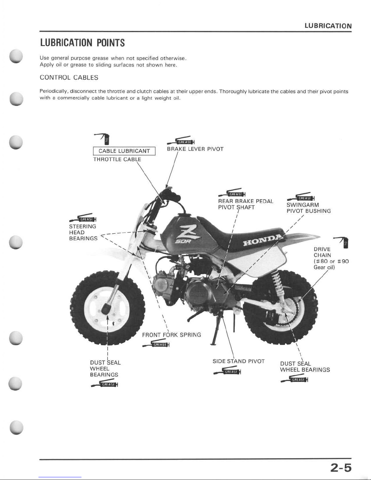
LUBRICATION
POINTS
Use general purpose grease when
not
specified
otherwise.
Apply
oil
or
grease
to
sliding surfaces
not
shown
here.
CONTROL CABLES
LUBRICATION
Periodically, disconnect the
throttle
and
clutch
cables at
their
upper ends. Thoroughly lubricate
the
cables and their
pivot
points
with a commercially
cable
lubricant
or
a light
weight
oil.
.~
I
CABL
E LUBRICANT
THROTTLE
BRIIKE
LEVER
PIVO
T
.--
STEERING
HEAD
BEARINGS
I
I
DUST
~EAL
WHEEL
BEARI
NGS
.~
\
\
\
,
FRONT FORK SPRING
.~
.~
REAR BRAKE PEDAL
PIVOT SHAFT
I
I
I
SIDE PIVOT
.em
•
oe;;;"
SWINGAAM
PIVOT BUSHING
\
\
\
DRIVE '
CHAIN
(;1:80 or
;90
Gear il
DUST SEAL
WHEEL BEARINGS
.--
2-5
3.
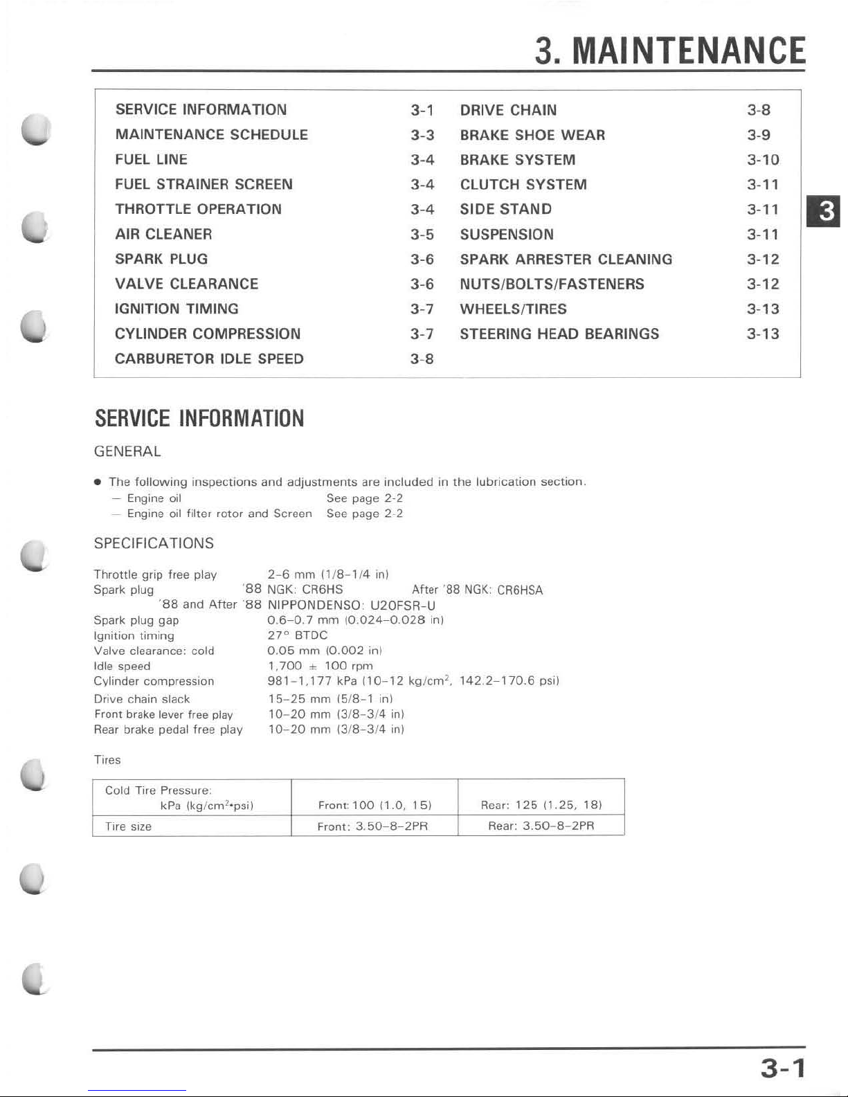
MAINTENANCE
SERVICE INFORMATION
3-1 DRIVE CHAIN
MAINTENANCE SCHEDULE
3-3
BRAKE SHOE WEAR
FUEL
LINE
3-4 BRAKE SYSTEM
FUEL STRAINER SCREEN 3-4 CLUTCH SYSTEM
THROTTLE OPERATION 3-4 SIDE
STAND
AIR CLEANER 3-5 SUSPENSION
SPARK
PLUG
3-6
SPARK ARRESTER CLEANING
VALVE CLEARANCE 3-6
NUTS/BOLTS/FASTENERS
IGNITION TIMING
3-7
WHEElSITIRES
CYLINDER COMPRESSION
3-7
STEERING HEAD BEARINGS
CARBURETOR IDLE
SPEED
3-8
SERVICE
INFORMATION
GEN
ERA
L
• The
following inspections
and
adjustments
are
included
in
the
lubrication
sectio
n.
- Engine
oil
See
page 2-2
- Engine
oil filter rotor and Screen
See
page 2-2
SPEC
IFI
CATIONS
Throttle
grip free
play
2-6 mrn 11/8- 1/4 in)
Spark plug '
S8
NGK: CA6HS After '
88
NGK:
CR6HSA
'S8 and
After
'S8 NIPPQNDENSO: U20FSR -U
Spark plug gap 0.
6-0
.7
mm
(0.024-0.028
inl
ignition liming
27"
BlOC
Valve clearance: cold 0.
05
mm 10.
002
in)
Idle speed
1,700
± ,
00
rpm
Cylinder
compression
981
- 1,
177
kPa
(10-12
kg/
em
2
,
142.2
- '
70.6
psi)
Drive chain slack
Front brake lever
free
play
Rear
brake
pedal
free
play
Cold Tire Pressure:
kPa
(kg/
cm2·psi)
15-25
mm
(5/8- 1
in
)
10-20
mm
13/8- 3/4 in)
10-20
rnm
13
/8 - 3/4 in)
Front: 1
00
(1.0
,
15
)
Rear:
125 (1.25,
18)
Tire size
Front:
3.50-8
- 2PR
Rear:
3.50
- 8- 2PR
3-8
3-9
3-10
3-
11
3-
11
3-
11
3-
12
3-
12
3-
13
3-
13
3-1
11
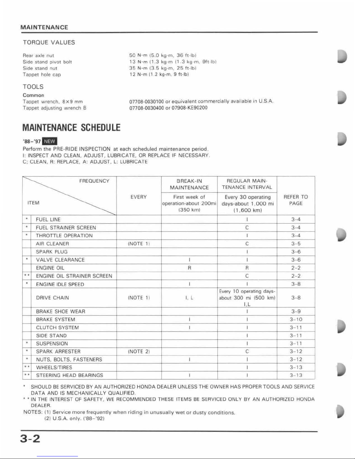
MAINTENANCE
TORQUE VALUES
Re
ar axle
nut
Si
de
stand
PivOt
bolt
Side
stand
nut
Tappet hole cap
TOOLS
Common
50
N·m (5.0 kg-rn,
36 h-I
b)
13
N'm
(1.3
kg-m (1.3 kg-m
9ft-lb
)
35 N' m 13.5 kg·m,
25 It·lbl
12
N'm
n 2 kg-m. 9 il-Ib)
Tappet
wren
ch ,
8x9
mrn
T appel adjusting
wrench
B
07708-0030100
or
equivalent
commercially
available in U.S.A.
07708-0030
400 or Q790B-KE90200
MAINTENANCE
SCHEDULE
'88-'97 _
Perform the PRE-A I
DE
INSPECTION at each schedu led maintenance penod.
I: INSPECT
AND
CLEAN,
ADJUST
, LUBRICATE,
OR
REPLACE IF NECESSARY.
C; CLEAN,
A: REPLACE, A:
ADJUST
, l : LUBRICATE
~
BREAK-IN
MAINTENANCE
EVERY
First week
of
ITEM
operation-about
200mi
(350
km)
,
FUEL LINE
·
FUEL STRAINER SCREEN
·
THROTTLE
OPERATION
AIR CLEANER !NOTE
11
SPARK
PLUG
·
VALVE
CLEARANCE
I
ENGINE
OIL
R
..
ENGINE OIL STRAINER SCREEN
·
ENGI NE IDLE SPEED
I
DRIVE
CHAIN
INOTE
1) I, l
BRAKE SHOE
WEAR
BRAKE
SYST
EM I
CLUTCH
SYSTEM
1
SIDE
STANO
·
SUSPENSION
·
SPARK ARRESTER
(NOTE
2)
·
NUTS, BOLTS
. FASTENERS 1
..
WHEELSITIRES
..
STEERING
HEAD
BEARINGS 1
REGU
LAR
MAIN
·
TENANCE
INTERVAL
Every
30
operating
days-about
1.000
ml
(1,600
km)
I
C
I
C
1
1
R
C
1
Ellery
10
operating days-
about
300
mi
(500
km)
I,l
1
1
1
1
1
C
1
1
1
REFER TO
PAGE
3- 4
3-4
3-4
3- 5
3 6
3-6
2- 2
2-2
3-6
3- 8
3- 9
3-
10
3-
11
3-
11
3-
11
3-
12
3-
12
3-
13
3-
13
•
SHOULD
BE
SERVICED BY
AN
AUTHORI2ED
HONDA
DEALER
UNLESS THE
OWNER
HAS
PROPER
TOOLS
AND
SERVICE
DATA
AND
IS
MECHANICALLY
QUALIFIED
.
•
'IN
THE INTEREST
OF
SAFETY,
WE
RECOMMENDED THESE ITEMS
BE
SERVICED
ONLY
BY
AN
AUTHORIZED
HONDA
DEALER.
NOTES
:
(1)
Service
more
frequently
when
riding
in
unusually
wei
or
dusty
conditions
.
(2) U.S.A.
only
. ('88-'92)
3 -2
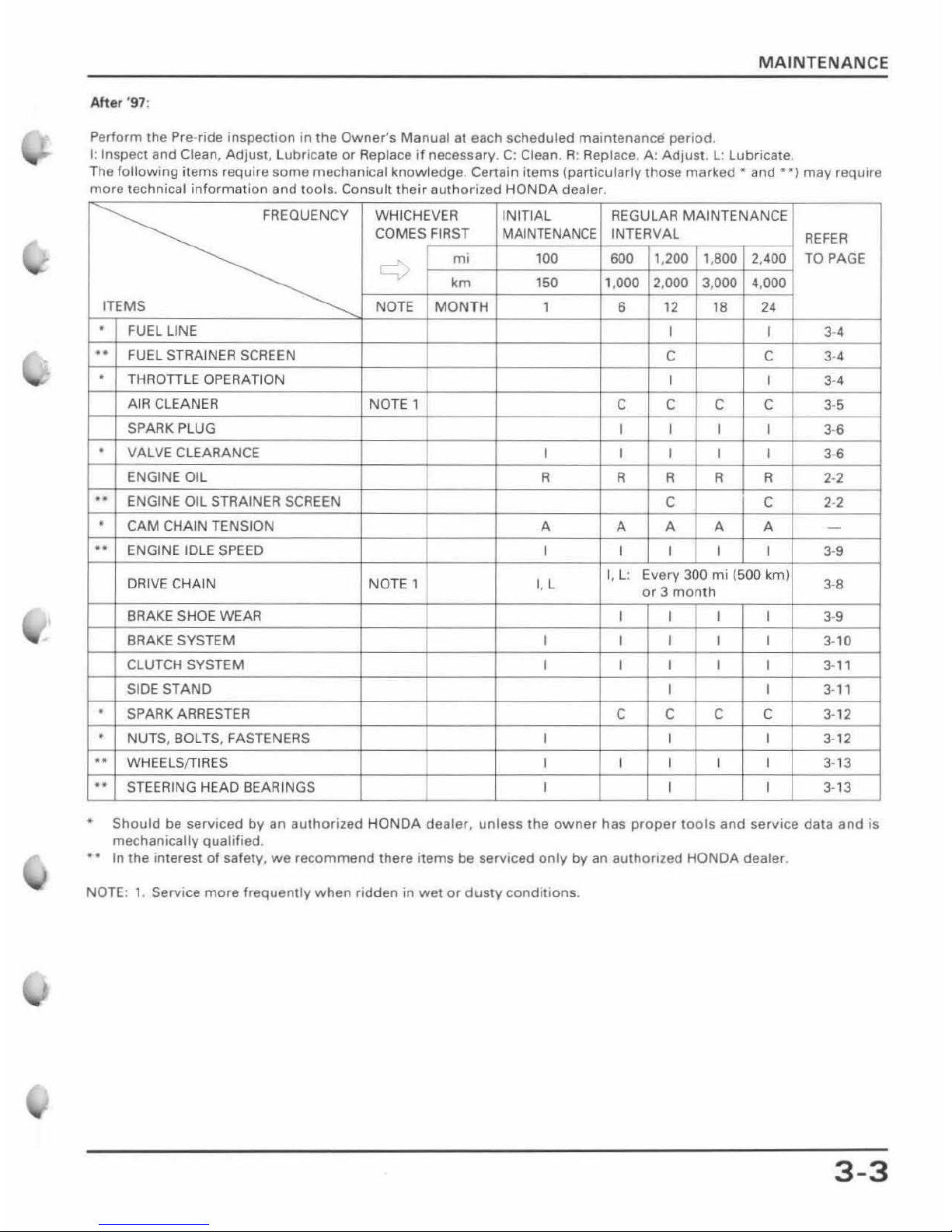
MAINTENANCE
After
'97:
Perform the Pre-ride
inspection
in
the
Owner
's
Manual
at each sche
duled
maintenance
period
.
I: Inspect and Clean,
Adjust
, l ubricate or Replace if necessary. C: Clean. R: Replace. A:
Adjust
. l :
lubricate
.
The
following
items
requite
some
mechanical
knowledge
. Certain
items
(particularlv
those
marked·
and
**)
may
requtre
more
technical
information
and
lools
Consult
their
authorized
HONDA dealer
FREQUENCY
WHICHEVER
INITIAL
REGULAR
MAINTENANCE
COMES FIRST
MAINTENANCE
INTERVAL
REFER
c-:
m;
100
600
1,200 1,
800
2,400
TO
PAGE
km 150
1,
000
2,000 3,000 4,000
ITEMS
NOTE
MON
TH 1
6
12
lB
2'
•
FUEL
LINE
1 1
3-'
..
FUEL
STRAI
NER
SCREEN
C C
3-'
•
THROTIl E
OPERATION
1 1
3-'
AIR CLE
ANER
NOTE
1
C C C C
3-5
SPARK PLUG
1 1
1
I
3-6
·
VALVE CLEARANCE
1 1 1 1 1
3-6
ENGINE OIL R
R R R R
2-2
· . ENGINE OIL STRAINER SCREEN
C C 2-2
·
CAM
CHAIN TENSION
A A A A A -
..
ENGINE IDLE SPEED
1 1 1 1 1 3-9
DRIVE
CHAIN
NOTE
1 I, L
I, l : Every 300
mi
(500 km)
3-B
or 3 month
BRAKE SHOE WEAR
1
1
1 1 3-9
BRAKE SYSTEM 1 1 1 1 1 3-10
CLUTCH SYSTEM
1 1 1
1
1
3-
l'
SIDE STAND 1 1 3-
11
•
SPARK ARRESTER
C C
C C
3-12
•
NUTS, BOLTS, FASTENERS 1 1 1 3-12
..
WHEElS/TIRES
1 1
1 1 1
3-13
..
STEER
ING HEAD BEARINGS 1
1
1 3-13
Should
be
serviced
by
an
authorized
HONDA
dealer, unless
the
owner
has
proper
tools
and
service
data
and
is
mechanically
qualified
_
••
In the interest
of
safety,
we
recommend
there
items
be
serviced
only
by
an
authorized
HONDA
dealer.
NOTE:
1. Service
more
frequently
when
ridden in
wet
or
dusty
conditions.
3-3
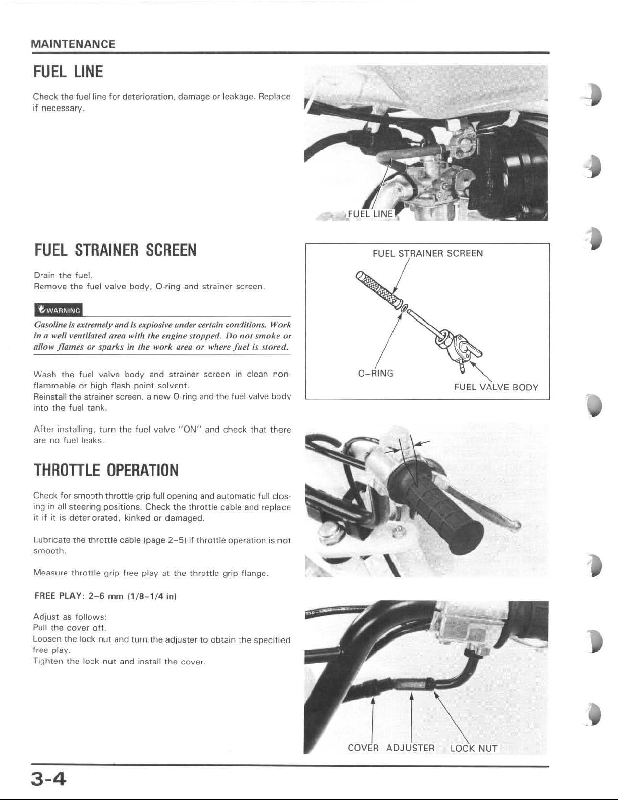
MAINTENANCE
FUEL
LINE
Check the fuel line for deterioration, damage or leakage. Replace
if
necessary.
FUEL
STRAINER
SCREEN
Drain the fuel.
Remove
the
fuel valve
body
, D-ring and strainer screen .
, '
Ga50fine is extremely
Qnd
is explos;I'e
under certain conditions.
Work
in a well velltilaled afeu with the engine stopped. Do not s
moke
or
allow flames or sparks in the work area or whe
re
jllel is stored.
Wash
the
fuel valve
body
and strainer screen in
clean
non
-
flammable or high flash point solvent.
Reinstall
the strainer screen, a
new
D-ring and the fuel valve body
into the fuel tank.
After
installing. turn the fuel valve "
ON"
and check that there
are
no fuel leaks .
THROTTLE
OPERATION
Check for smooth throttle grip full opening and automatic full clos-
ing in all
steering
positions
. Check the
throttle
cable and replace
it if it
is
deteriorated, kinked or damaged.
Lubricate the
throttle
cable (page 2-
5)
if
throttle
operation is
not
smooth
,
Measure
throttle
grip free play at the
throttle
grip flange .
FREE
PLAY :
2-6
mm
(1/8-
1/4 in)
Adjust
as
follows
:
Pull
the cover
off.
Loosen the lock nut and turn the adjuster
to
obtain the specified
free
play.
Tighten
the
lock
nut
and install the cover .
3-4
•
~".,"'"
"""
/
O-RING
"""
FUEL VALVE
BODY
--
\
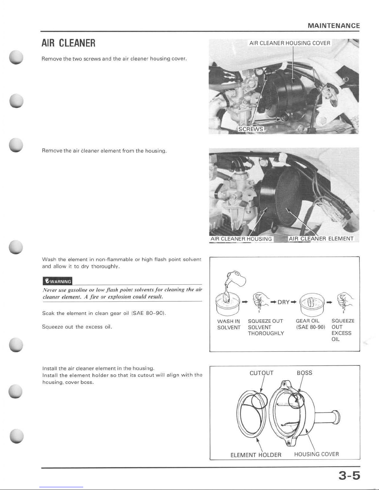
AIR
CLEANER
Remove the
two
screws
and the air cleaner
housing
cover.
Remove the air cleaner
element
from
the
housing.
Wash
the
element
in
non-flammable
or
high
flash
point
solvent
and
allow
it
to
dry
thoroughly.
,
,I
!Vertr use gasoline or low flash
poim
SO/I't'rllS
jor
cleaning the air
cleaner element. A fire or explosion could
re.~ull
.
Soak the element in clean gear oil (SAE
80-90).
Squeeze
out
the
excess
oil.
Install
the
air
cleaner
element
in
the
housing
.
Install
the
element
holder
so
that
its
cutout
will
align
with
the
housing,
cover
boss.
MAINTENAN
CE
AIR
CLEANER
HO:USINC
COVER
WASH
IN
SOLVENT
saUEEZEOUT
SOLVENT
THOROUGHLY
CUTOUT
\
ELEMENT HOLDER
GEAR OIL
(SAE 80-90)
BOSS
SQUEEZE
OUT
EXCESS
OIL
HOUSING
COVER
3-5
MAINT
ENANCE
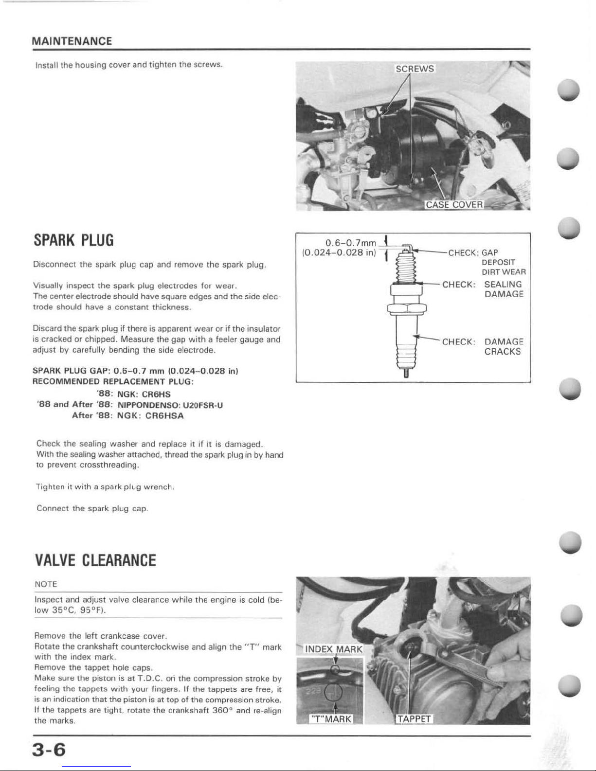
Insta11
the
housing
cover
and
tighten
the
screws
.
SPARK
PLUG
Disconnect the spark plug cap and remove the spark plug.
Visually inspect the spark plug electrodes for wear.
Tile center electrode should have square edges and the side elec trode should have a
constant
thickness.
Discard the spark plug
if
there
is
apparent wear or
if
the
insulator
is
cracked or chipped. Measure the gap
with
a feeler gauge and
adjust
by
carefully
bending the side electrode.
SPARK
PLUG
GAP: 0 .6- 0.1 mm (0.024-0 .
028
inl
RECOMMENDED
REPLACEMENT
PLUG
;
'88:
NGK
: CR6HS
'
88 and
After '88
: NJPPONDENSQ: U20FSR·U
Aft
er 'S8:
NGK
: CR6H SA
Check the sealing washer and replace
it
if
it
is damaged.
With
the
sealing
washer
attached, thread the spark plug
in
by hand
to preven
t crossthreading.
Tighten it
with
a spark plug wrench.
Connect the spark plug cap.
VALVE
CLEARANCE
NOTE
Inspect and adjust valve clearance while the engine
is
cold (be-
low 35°
C,
95°F).
Remove the left crankcase cover.
Rotate the
crankshaft counterclockwise and align
the
"T"
mark
with
the index mark.
Remove the tappet hole caps.
Make sure the piston is at
T.O.C. on the compression stroke
by
feeling the tappets
with
your fingers.
If
the
tappets are free,
it
is
an
indication
that
the piston is at top of the compression stroke.
If the
tappets are tight, rotate the crankshaft
360°
and re-align
the mark
s.
3-6
0.6-0.
7mm
=
Jr.
~
J;o-
--'CH"CK'
~0.024-0.028
in
)
GAP
DEPOSIT
DIRT WEAR
CHECK: SEALING
DAMAGE
CHECK: DAMAGE
CRACKS
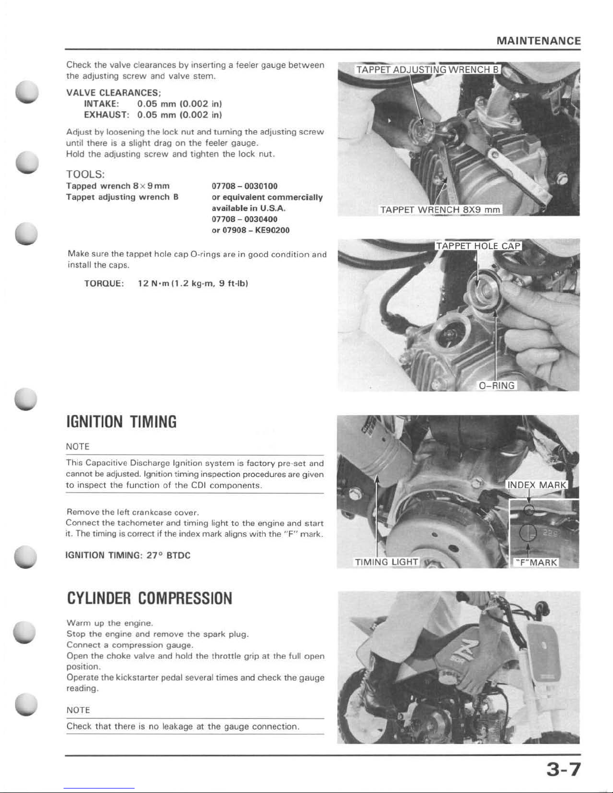
Check the valve clearances
by
Inserting a feeler gauge
between
the adjusting
screw
and valve stem.
VA
LVE CLEARANCES ;
INTAkE: 0.
05
mm 10.
002
inl
EXH
AUST; 0.
05
mm 10.
002
inl
Adjust by loosening the lock nut and turning the
adjusting
screw
until there
is
a slight drag
on
the feeler gauge.
Hold the
adjusting
screw
and
tighten
the
lock
nut.
TOOL
S:
Tapped
wren
ch 8 x 9
mm
Tappet adjusting
wren
ch 8
07708 - 0030100
or
equivalent
commerdalty
available in U.S.A.
07708 - 0030400
or 07908 -
KE
90200
Make sure the tappe t hole cap
a-rings
are in good
condilion
and
install the caps.
TORQUE: 12 N·
m(1.2 kg
,m, 9 ft-I
bl
IGNITION
TIMING
NOTE
This Capacitive Discharge I
gnit
ion system
is
fact
ory
pre-set and
cannot
be adjusted. Ignition timing inspection procedures are given
to inspect the function of
the CDI components.
Remove
the left crankcase cover.
Connect the tachometer and
timing
light
to
the engine and Slart
it. The timing
is
correct
If
the index mark aligns
with
the "F" mark.
IGNITION TIMI NG: 27°
BlDC
CYLINDER
COMPRESSION
Warm
up
the
engine.
Stop
the
engine and remove the spark plug.
Connect
a compression gauge.
Open the
choke
valve and hold the
throttle
grip at the full open
position.
Operate the kickstarter pedal several times and
check
the gauge
reading.
NOTE
Check
tha t there
is
no
leakage at t he gauge connection.
MAINTENANC
E
3-7
MAINTENANCE
CYLINDER COMPRESSION: 981·' .1
77
kPa 110-' 2
k
gJcm~
14
2.2-170.6
psi)
L
ow
comp
ression can
be
caused
by:
Improper valve adjustment
Valve leakage
Blown cylinder head gasket
Worn piston ring
or
cylinder
Hig h
comp
ression can be caused by:
Carbon deposits in the
combustion
chamber
or
on
the
piston
crown
.
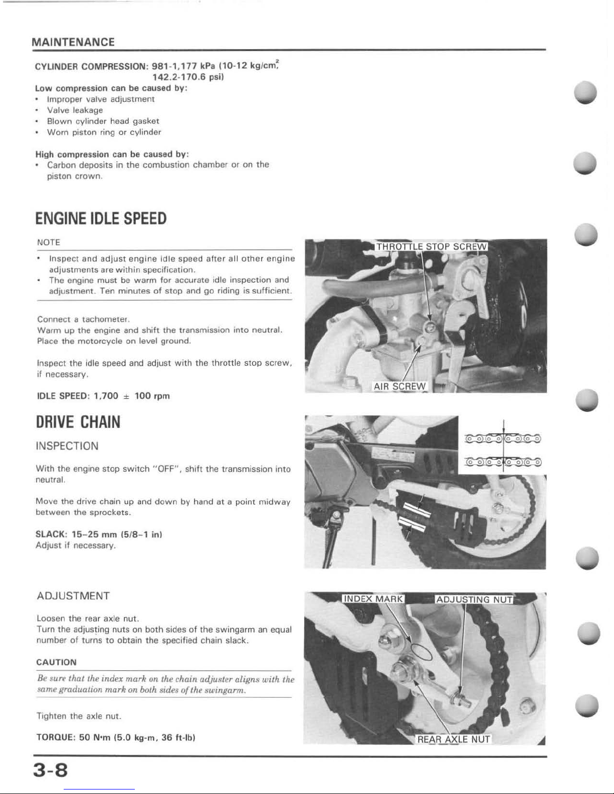
ENGINE
IDLE
SPEED
NOTE
Inspect and
adjust
engine
idle
speed
after
all
other
engine
adjustments are
within
specification .
The engine
must
be
warm
for accurate idle inspection and
adjustment .
ren
minutes
of
stop
and
go
riding is
sufficient
.
Connect a tachometer.
Warm up the engine and
shift
the
transmission
into
neutral.
Place the
motorcycle
on level ground .
Inspect the idle speed and adjust
with
the
throttle
stop
screw,
if
necessary.
IDLE S
PEED
: 1,
700 ± 10
0 rpm
DRIVE
CHAIN
INSPECTION
With
the engine stop
switch
"OFF
",
shift
the transmission
into
neutral.
Move
the drive chain
up
and
down
by
hand at a point
midway
between
the sprockets .
SL
ACK: 15-25
mm 15/8- 1 in)
Adjust
if
necessary .
ADJUSTMENT
Loosen the rear axle nut.
Turn the
adjus~ing
nuts
on
both
sides
of
the swingarrn an equal
number
of
turns to obtain the specified Chain slack.
C
AUTI
ON
Be su
re
that the
ITIda
mark
on the chain adju s
leraligns
with the
SlI
me graduation
mark
on both
sid
es o
{th
e BWlngarm.
Tighten the axle nut .
TORQUE:
50
Nom
{5.0 kg-m ,
36 ft·
lbl
3-8
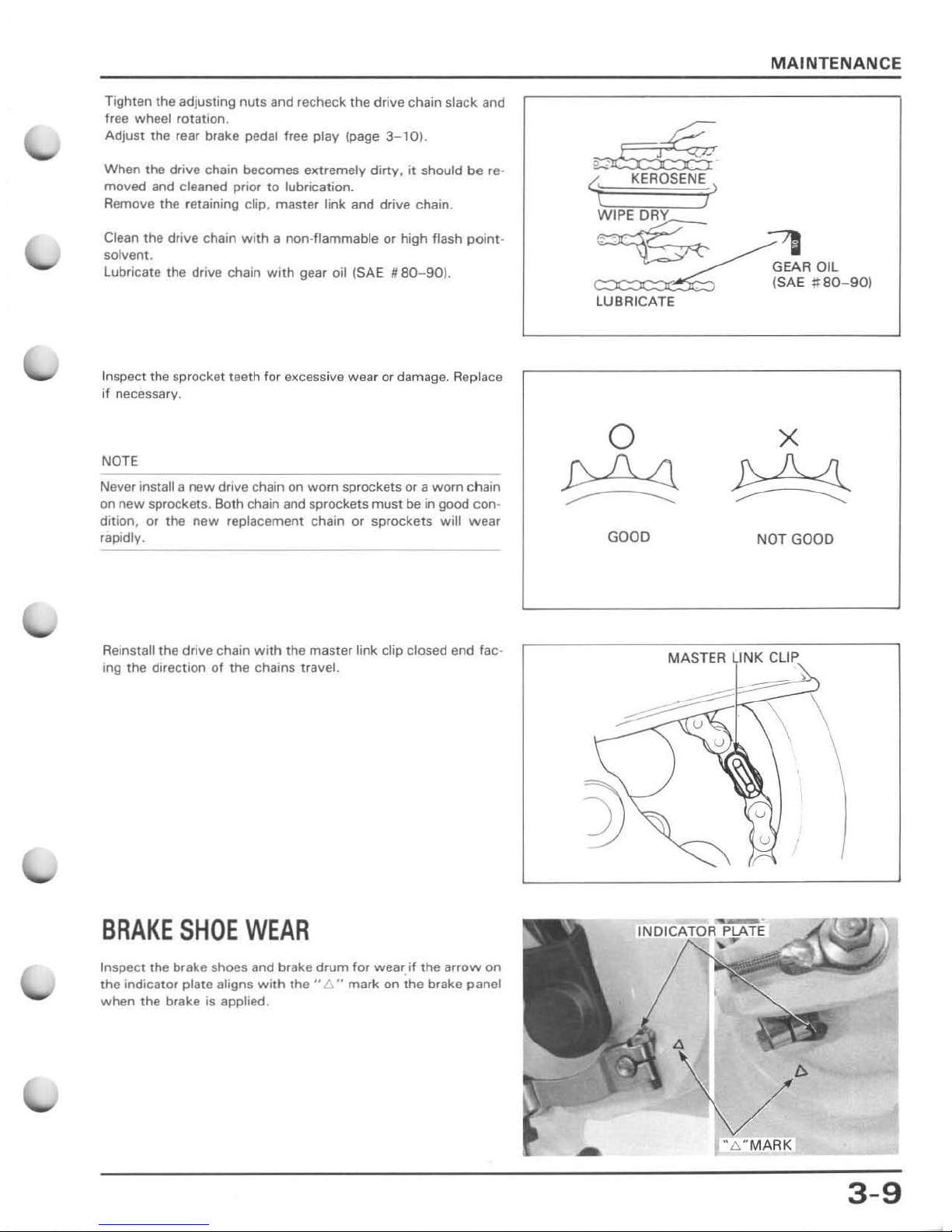
Tighten the adjusting nuts and recheck the drive chain slack. and
free wheel rotation,
Adjust
the
rear brake pedal free play (page
3-10).
When the drive chain becomes extremely
dirty,
it
should
be
re-
moved and cleaned prior
to
lubrication.
Remove the retaining clip. master link and drive chain.
Clean the drive chain
with
a non-flammable or high flash
poin
t-
solvent.
Lubricate the drive chain
with
gear oil (SAE
/lBO-90).
Inspect the sprocket
teeth
for
excess
ive
wear
or damage. Replace
jf necessary.
NOTE
Never install a new drive chain on
worn
sprockets or a worn chain
on
new
sprockets. Both chain and sprockets must be
in
good con-
dition, or the
new
replacement chain or sprockets
will
wear
rapidly.
Reinstall
the
drive chain
with
the master link clip closed end fac·
ing
the
direction of the chains travel.
BRAKE
SHOE
WEAR
Inspect the brake shoes and brake
drum
for wear.
if
the
arrow
on
the
indicator plate aligns
with
the"
l:::." mark
on
the
brake panel
when the brake is applied.
LUBRICATE
o
~
GOOD
MAINTENANCE
:71
GEAR
Oil
(SAE
;::80-90)
NOT GOOD
MASTER
LINK CLIP
\)
3-9

MAINTENANCE
BRAKE
SYSTEM
FRONT BRA
KE LEV
ER
FREE
PLAY
Measure the
front
brake lever free play
at
the
tip
of
the
brake lever.
FREE
PLAY : 10-20 mm
(3/8-314 in)
If
necessary, turn
the
adjusting
nut
to obtain the specified free
play .
REAR BRA
KE
PEDAL
FRE
E PLAY
Check the brake pedal free play
FREE
PLAY: 10-2
0
mm
(3/
8- 3/4
in
)
If
necessary, turn
the
adjusting
nut
to
obtain
the
specified
free
play .
NOTE
Make
sure the
cutout
on
the adjusting
nut
is seated on t
he
brake
arm pin
after
making
the final free
play
adjustment.
3-10
AD",us
irIN
G NUT
..
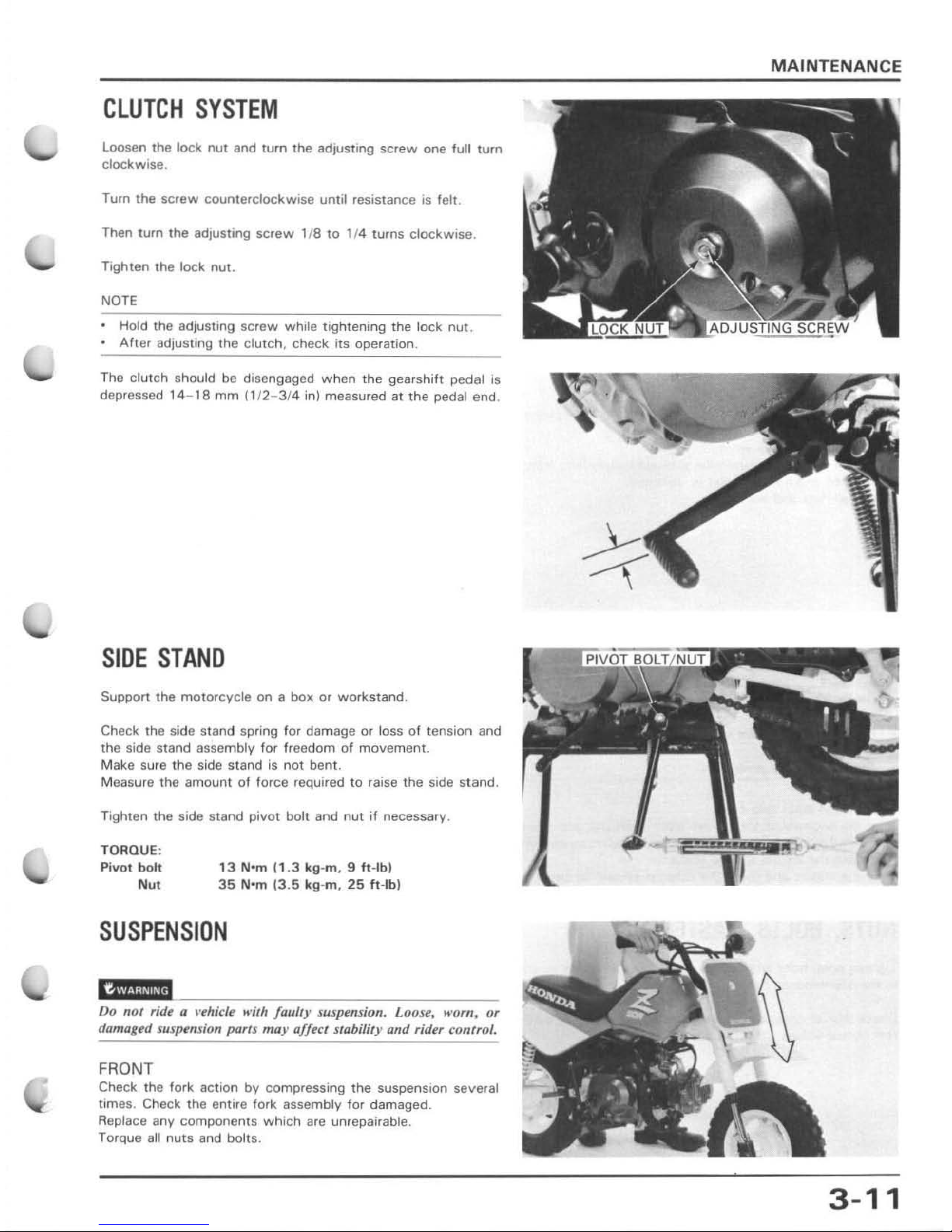
CLUTCH
SYSTEM
loosen
the
lock
nut
and
turn
the
adjusting
screw
one
full
turn
clockwise
.
Turn the
screw
counterclockwise
until
resistance
is
felt .
Then turn the adjusting
screw
118
to 1/4 turns
clockwise
.
Tighten the lock nut.
NOTE
Hold the adjusting
screw
while tightening the lock nut.
•
After
adjusting
the
clutch,
check
its
operation.
The
clutch
should be disengaged
when
the
gearshift pedal is
depressed
14 -
1a
mm
(1/2- 3/4 in] measured at
the
pedal end.
SIDE
STAND
Support the
motorcycle
on a box or
workstand
.
Check the side stand
spring for damage or loss of tension and
the side stand assembly for freedom
of
movement.
Make sure
the
side stand
is
not
bent.
Measure
the
amount
of
force required to raise
the
side stand.
Tighten the side stand pivot
bolt and
nut
if
necessary .
TORQUE:
Pivot bolt
Nu.
13
N'm
(1.3
kg-m, 9 ft-Ib)
35
N'm
(3.5
kg
-m,
25
ft
-Ib)
SUSPENSION
"ehicle
....
ith
faulty
suspension. Loose. K'
om.
or
damaged suspension parts
may
affect stability and rider (ontrol.
FRONT
Check the fork action
by
compressing
the
suspension several
times. Check the entire fork assembly for damaged.
Replace any components
which
are umepairable.
Torque all
nuts
and bolts .
MAINTENANCE
3-11
MAINTENANCE
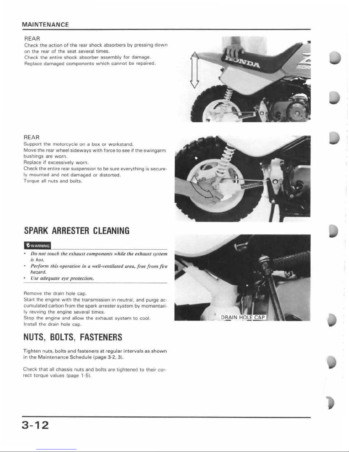
REAR
Check the action
of
the
rear Shock absorbers by preSSing
down
on the feBr
of
the seal several
limes
.
Check the entire shock absorber assembly for damage .
Replace damaged components
which
cannot
be
repaired.
REAR
Suppo"
the
motorcycle
on
a box
or
workstand
.
MOlle
the
rear wheel
sideways with force
to
see if
the
sWlngarm
bushings are
worn
.
Replace If excessively worn.
Check the
enwe
rear suspension
to
be
sure
everything
is secure·
Iy
mounted
and
not
damaged
or
distorted.
Torque
all
nuts
and bolts.
SPARK
ARRESTER
CLEANING
caiHMM
Do not touch
th
~
u hout, compontnu while the exhaust sysum
is
hot.
Pu/orm
Ihis
opualion
in Q k'eff·,'
emiloud
Qua, /rl!t!
from
/irt!
ha::'fud.
USI!
odequ
Qu
e)'j>
pr(J/t!clioll.
Remolle the drain hole cap.
Start the engine
with
the
transmission In neutral. and purge ac-
cumulated carbon from the spark arrester
system
by
momentari
-
ly
revving the engine several times .
StOp the engine and
allow
the exhaust
system
to
cool.
Install the drain hole cap .
NUTS, BOLTS,
FASTENERS
Tighten
nuts,
bolts
and
fasleners
81
regular intervals
as
shown
In
the Maintenance
Schedule (page
3-2, 3).
Check that all
chasSIS
nuts
and bolts are tightened to the ir
COf'
rect torQue values
{page'
·5).
3-12
 Loading...