

Page 1
GX240
GX270
GX340
GX390
UT2/RT2
Technical Manual
©2010 American Honda Motor Co., Inc.
All Rights Reserved
PTR54179
Page 2

Page 3

GX240 • GX270 • GX340 • GX390 (UT2/RT2) Technical Manual
Preface
This manual covers engine selection, engine installation design and engine installation testing, so the combination of a
Honda engine and your equipment will make the best possible product.
Please feel free to contact your Honda Engine Distributor at any time for additional technical information or to discuss
your engine application needs.
All information contained in this manual is based on the latest product information available at the time of printing. We
reserve the right to make changes at anytime without notice.
No part of this publication may be reproduced, or transmitted, in any form or by any means, electronic, mechanical
photocopying, recording or otherwise, without the prior written permission of the publisher. This includes text, figures
and tables.
Contents
Design Features .......................................................... 2
Emission Regulations ................................................. 2
Recommended Power Range ..................................... 3
Maximum Operation ............................................... 3
Continuous Operation ............................................ 3
Power Curve .......................................................... 3
Output Confirmation Methods ................................ 5
Cooling ....................................................................... 5
Minimum Cooling Air Flow Requirement ................ 5
Ambient Temperature Limits .................................. 5
Testing ................................................................... 5
Engine Enclosures ................................................. 6
Fuel System ................................................................ 7
Fuel Tank Position ................................................. 7
Fuel Line ................................................................ 7
Fuel Valve Installation ............................................ 7
Fuel Pump ............................................................. 7
Fuel Tank Filter Installation .................................... 7
Controls ....................................................................... 7
Engine Switch ........................................................ 7
Carburetor Controls ............................................... 8
Exhaust System .......................................................... 9
Recommended Muffler ........................................... 9
Fabricated Exhaust Systems ................................. 9
Engine Mounting ....................................................... 10
Inclination ............................................................. 10
Resonance Check ............................................... 10
Electrical System ...................................................... 11
Battery ................................................................ 11
Fuse ..................................................................... 11
Engine Switch ...................................................... 11
Charging Coil Selection ....................................... 12
Lamp Coil Kit (optional) ........................................ 12
Oil Alert® System (optional) ................................ 12
Wiring Precautions ............................................... 12
Wiring Diagrams ....................................................... 13
No Charge Coil Models ........................................ 13
Electric Start Models ............................................ 13
Power Transmission ................................................. 15
V-Belt Connections .............................................. 15
Starting Performance ...........................................16
Installation Considerations ........................................17
Maintenance Points Accessibility ........................17
Dimensional Drawings ...............................................19
GX240-270 ...........................................................19
GX340-390 ...........................................................23
PTO Dimensional Drawings ......................................27
H Type (with reduction) ........................................27
L Type (with reduction) .........................................27
P Type ..................................................................28
Q Type ..................................................................28
S Type ..................................................................29
V Type ..................................................................29
W Type .................................................................30
Dimensions and Weights ...........................................31
GX240 ..................................................................31
GX270 ..................................................................33
GX340 ..................................................................34
GX390 ..................................................................35
Specifications ............................................................36
GX240 ..................................................................36
GX270 ..................................................................36
GX340 ..................................................................37
GX390 ..................................................................38
Serviceability .............................................................39
Maintenance Schedule .........................................39
Engine Oil Level Check ........................................40
Engine Oil Change ...............................................41
Air Cleaner Check/Cleaning and Replacement ....41
Sediment Cup Cleaning .......................................44
Spark Plug Check/Adjustment ..............................45
Spark Plug Replacement ......................................46
Spark Arrester Cleaning (if equipped) ..................46
Idle Speed Check/Adjustment ..............................47
Valve Clearance Check/Adjustment .....................48
Combustion Chamber Cleaning ...........................49
Fuel Tank and Filter Cleaning ..............................50
Fuel Tube Check ..................................................50
Evaporative emissions ...............................................51
Types with OEM provided fuel tanks ....................51
© 2010 American Honda Motor Co., Inc — All Rights Reserved 1
Page 4
GX240 • GX270 • GX340 • GX390 (UT2/RT2) Technical Manual
INTRODUCTION
Honda engines are designed for minimal maintenance.
When maintenance is required, the task is kept simple by
providing convenient maintenance access and procedures.
Honda engines use proven engine technology and design
innovations to make them highly reliable engines.
DESIGN FEATURES
High Performance
OHV design reduces thermal distortion of the cylinder. This
helps maintain the optimum seal between the piston rings
and cylinder, which minimizes oil and fuel consumption.
Power is also maintained in extreme operating conditions.
Smooth and Quiet Operation
OHV design provides a reduced reciprocating mass and
balanced weight distribution. The 25° inclined cylinder
produces a low center of gravity for the moving parts, which
further reduces vibration for quiet operation. These features,
and the compact design result in extremely smooth
operation.
Use of proven design technologies reduces noise from
internal engine components. The hardness of reciprocating
parts, the helical cut gears on the crankshaft and camshaft
and the use of select materials makes these engines
exceptionally quiet. The large muffler is designed to further
reduce noise.
Durability/Reliability
Honda engines are built with quality that provides proven
durability and reliability. Proven features such as OHV
design and cast iron cylinder sleeve provide long life in all
types of operating conditions. To further enhance the
reliability of these engines, a 2-stage air cleaner system,
digital electronic ignition system, mechanical centrifugal
governor and proven side-draft carburetor are standard
features.
EMISSION REGULATIONS
The Honda GX390 engines meet U.S. Environmental
Protection Agency and the California Air Resources Board
regulations.
Honda engine distributors and equipment manufacturers
that use Honda engines are required by regulation to follow
this OEM technical manual. Correct engine matching
ensures that the engine will be durable (and emission
durable) in use.
2 © 2010 American Honda Motor Co., Inc — All Rights Reserved
Page 5
GX240 • GX270 • GX340 • GX390 (UT2/RT2) Technical Manual
ENGINE SPEED
(rpm)
2000 36003000
(KW)
(HP)
OUTPUT
TORQUE
13
14
15
7
6
5
4
8
9
(PS)
7
6
5
4
8
9
20
NET POWER
NET TORQUE
12
11
1.6
1.7
1.8
1.9
2.0
1.5
18
16
14
3
2
4
5
6
7
(N·m)
(lbf·ft)
(kgf·m)
RECOMMENDED OPERATING SPEED RANGE
ENGINE SPEED
(rpm)
2000 36003000
(KW)
(HP)
OUTPUT
TORQUE
13
14
15
7
6
5
4
8
9
(PS)
7
6
5
4
8
9
20
NET POWER
NET TORQUE
12
11
1.6
1.7
1.8
1.9
2.0
1.5
18
16
14
3
2
4
5
6
7
(N·m)
(lbf·ft)
(kgf·m)
RECOMMENDED OPERATING SPEED RANGE
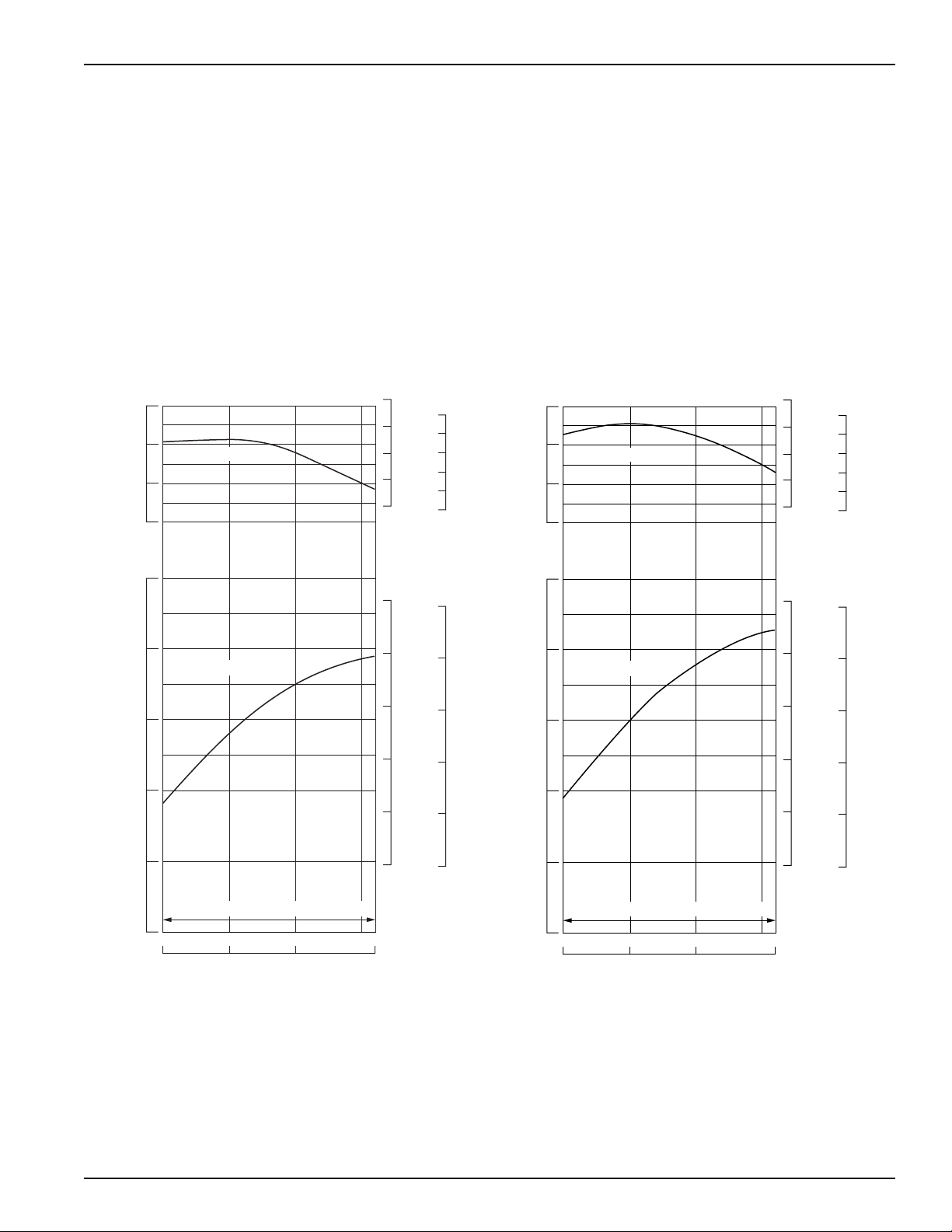
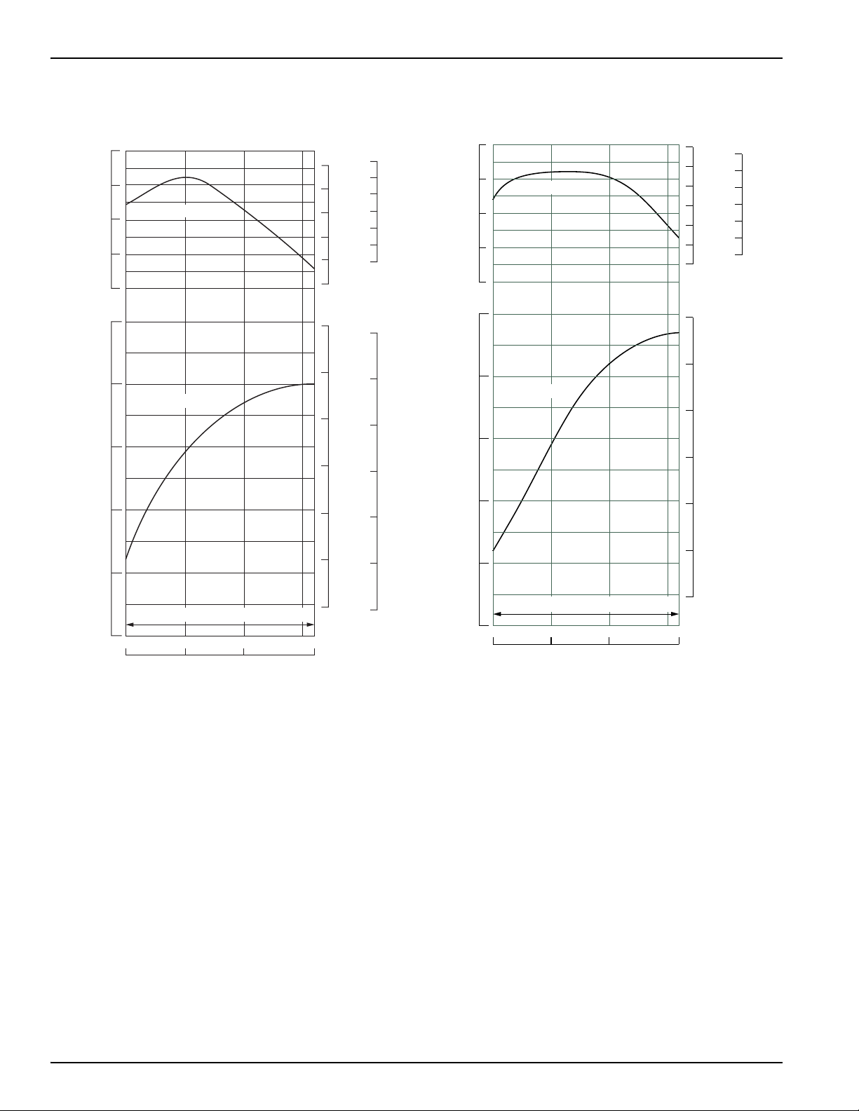
RECOMMENDED POWER RANGE
Maximum Operation
Operate the engine at not more than 90% of the maximum horsepower available at a given rpm.
Recommended maximum operating hp = 0.9 x maximum hp
Continuous Operation
For continuous operation (more than 30 minutes), operate the engine at not more than 80% of the maximum
horsepower available at a given rpm.
Continuous recommended operating hp = 0.8 x maximum hp
Power Curve
GX240 GX270
© 2010 American Honda Motor Co., Inc — All Rights Reserved 3
Page 6
GX240 • GX270 • GX340 • GX390 (UT2/RT2) Technical Manual
ENGINE SPEED
2000 36003000
RECOMMENDED OPERATING SPEED RANGE
(min-1 [TRO])
(N·m)
28
(KW)
(HP)
(lbf·ft)
(kgf·m)
9
8
7
OUTPUT
TORQUE
6
6
19
2.6
2.7
2.8
20
21
7
8
9
10
11
12
5
4
26
24
NET POWER
NET TORQUE
16
17
18
15
2.3
2.4
2.5
2.2
22
20
GX340 GX390
(N·m)
28
26
24
TORQUE
22
20
(KW)
9
8
7
OUTPUT
6
NET TORQUE
NET POWER
(lbf·ft)
20
19
18
17
16
15
(HP)
12
11
10
9
8
(kgf·m)
2.8
2.7
2.6
2.5
2.4
2.3
2.2
(PS)
12
11
10
9
8
5
RECOMMENDED OPERATING SPEED RANGE
4
2000 36003000
ENGINE SPEED
(rpm)
7
6
7
6
4 © 2010 American Honda Motor Co., Inc — All Rights Reserved
Page 7
GX240 • GX270 • GX340 • GX390 (UT2/RT2) Technical Manual
rpm with load
rpm without load
1-
()
100% ≤ 5%
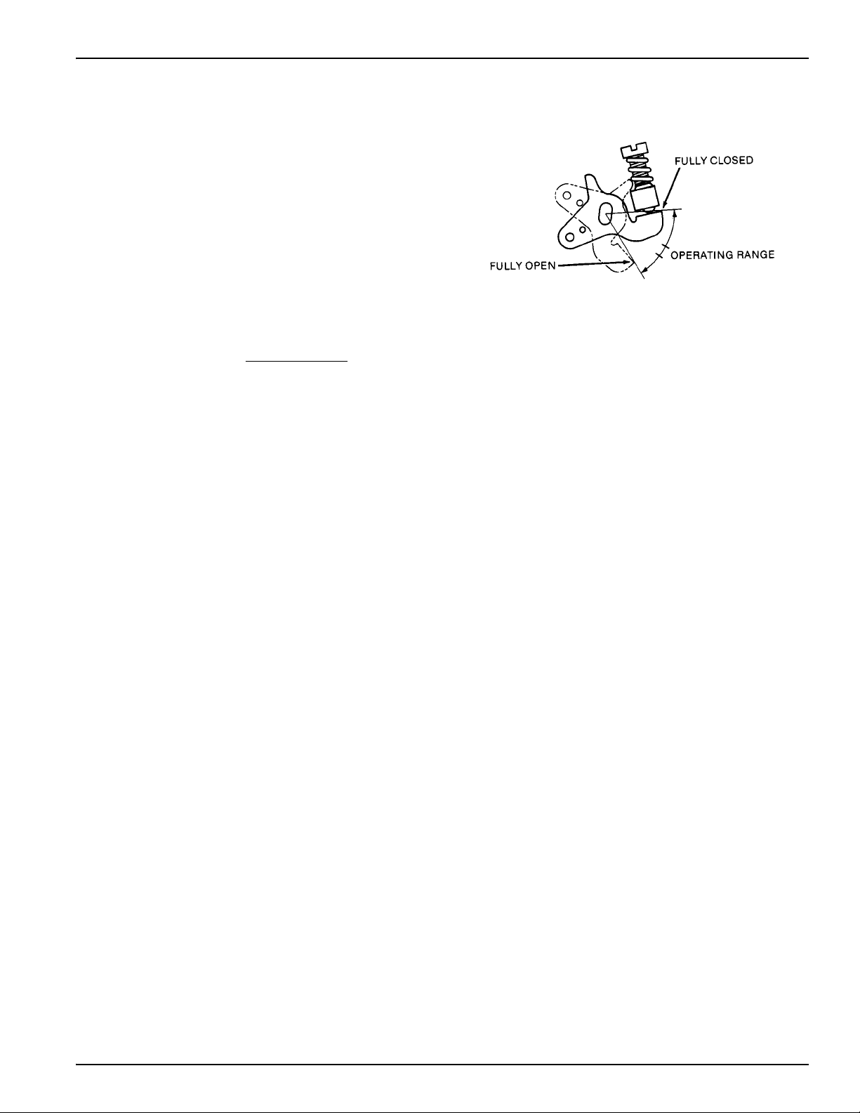
Output Confirmation Methods
Governor Rod Measurement
When the engine is properly matched and operating at
its continuous rated load, the carburetor throttle angle
should be approximately half way between full open
and full closed positions.
Bring the engine to normal operating temperature and
then apply the expected continuous load. If the throttle
is more than halfway open, the engine is being
overloaded resulting in overheating and shortened
engine life.
Tachometer RPM Measurement
Normal governor droop can also be used to measure engine load.
At rated speed:
Engine is operating within the continuous recommended power range.
COOLING
Minimum Cooling Air Flow Requirement
Engine enclosure must have the minimum cooling air flow listed below.
3
GX240/GX270: 7 m
GX340/GX390: 8 m
Ambient Temperature Limits
-15 to +40°C (+5 to +104°F)
Testing
• Use thermocouple temperature probes at the specified locations.
• Operate the engine under worst-case conditions
• An electronic data logger is required for the temperature data collection
• Set up the data logger to take multiple readings per minute. If data is being taken manually, a reading every 5
minutes is adequate.
• Take readings until the engine oil temperature is stabilized at continuous rated load
• Run the application for one hour of continuous operation; the temperatures should be stabilized in that time. If the
application is used only for short intervals, note the normal run time in the application document.
• Shut the engine down and continue to take readings. Attempt to restart the engine after heat soaking for 5 minutes.
• For enclosed applications, fuel bowl temperature should be monitored after testing until the maximum is reached -
this may take several minutes
(247 ft3) per minute at 3,600 rpm
3
(282 ft3) per minute at 3,600 rpm
© 2010 American Honda Motor Co., Inc — All Rights Reserved 5
Page 8

GX240 • GX270 • GX340 • GX390 (UT2/RT2) Technical Manual
Maximum Operating Temperatures
Spark plug Seat 270 °C (482 °F)
Engine Oil 140 °C (284 °F)
Gasoline at Carburetor Float Bowl 60 °C (140 °F)
Gasoline at Carburetor Float Bowl (after 5 min. hot soak) <70 °C (158 °F)
Gasoline at Fuel Tank 60 °C (140 °F)
These temperatures are based on an ambient temperature of 40°C (104°F). Compensate for any deviation linearly; i.e.,
if the ambient temperature is 20°C (68°F), the maximum acceptable oil temperature is 120°C (248°F).
Adjusted oil temperatures of less than 40°C will require more frequent oil changes.
Engine Enclosures
When the engine installation in the equipment obscures the emission label, a duplicate label must be applied. In this
case, as part of the engine matching process, it will be necessary to establish a process for the OEM to obtain
duplicate labels. EPA requires full documentation, control, and record keeping of the duplicate label process.
Cool Air Intake
The engine must be provided with a cooling duct so that fresh air can be drawn directly from outside the enclosure
cover. Install the cooling air duct with the intake port in a place free from dust and dirt. The cooling air volume changes
according to the shape of the duct and screen and the engine installation conditions. Operate the engine under the
normal operating conditions and be sure that the engine meets all temperature requirements.
The cooling air duct must have a cross-sectional area of at least 300 cm
When the engine is operated in dusty areas, install a filter at the enclosure inlet for the cooling air. This will reduce the
effective area, so you must increase the size of the inlet accordingly. Increase the size of the inlet to the point where
the maximum operating temperatures are not exceeded when operated under maximum load.
Install the cooling air duct and filter so that the filter can be easily checked, and dust, dirt and foreign material removed.
2
(46.5 sq in).
Hot Air Discharge
Hot air must be discharged directly outside the enclosure. Provide a discharge duct if necessary. The minimum cross
section of the hot air discharge opening must be larger than that of the cooling air inlet.
Locate the discharge port so the hot discharge air does not flow back into the enclosure. Provide sufficient ventilation to
prevent the engine compartment temperature from rising above ambient temperature limits after the engine has been
stopped.
Exhaust Discharge
The exhaust system becomes hot during operation and remains hot for a while after operation. Separate the exhaust
system from the engine compartment with a partition wall and locate the exhaust system in the discharged cooling air
flow.
Be sure the exhaust gas is directly discharged outside the enclosure without being blocked or restricted by any
obstacles. The exhaust gas must not flow back or be drawn back into the enclosure.
Provide the engine with an exhaust deflector or exhaust pipe extension if necessary.
If an extension pipe is used:
• Keep the length of the pipe as short as possible to keep exhaust backpressure within limits (see page 10).
• The extension pipe must have an ID larger than the OD of the muffler outlet.
• Verify the exhaust pipe extension does not create excessive vibration at any given engine rpm. If necessary, use
an exhaust pipe holder to support the exhaust pipe extension.
Grass Cutting Applications
When the engine is operated on grass cutting equipment, install a rotary screen grid on the cooling air intake port to
prevent the accumulation of large clippings.
Do not allow the grass clippings shredded by the rotary screen grid to accumulate around the intake port.
6 © 2010 American Honda Motor Co., Inc — All Rights Reserved
Page 9
GX240 • GX270 • GX340 • GX390 (UT2/RT2) Technical Manual
FUEL SYSTEM
If the engine is supplied with an incomplete fuel system (no fuel tank, no fuel hose, etc.), the OEM is responsible for
ensuring evaporative emission requirements/regulations are met, including certification.
Fuel Tank Position
If a remote fuel tank is used, it must be installed so that its maximum gasoline level is within 50 cm (19.5 in) above the
carburetor gasoline level. If a fuel pump is used, the maximum fuel level should be within 50 cm (19.5 in) above or
below the carburetor gasoline level.
Fuel Line
Use a low permeation fuel line (displaying an Executive Order number) rated for use with gasoline. The fuel line should
have an inside dimension of 5.5 mm (0.22 in). Keep the fuel line as short as possible. Install the fuel line so it will not
rest against any sharp objects or make sharp bends that can restrict the flow of fuel. If the fuel line passes through an
enclosure wall, protect the line with a rubber grommet. Route the fuel line away from hot engine and exhaust system
components and away from electrical wiring. Secure the fuel line to prevent sagging and bending.
Fuel Valve Installation
If a remote fuel tank is used, a fuel valve should be installed so it is easily accessible. Install the fuel valve at the outlet
of the fuel tank and use an easily read label to indicate valve location and operation. If under the fuel tank is not the
ideal location, securely install the fuel valve in-line with the fuel tube in a cool location, so that engine heat cannot
cause vapor lock.
Fuel Pump
A fuel pump should be selected that provides a maximum operating pressure of 0.1 kgf/cm2 (1.4 psi) and delivers 15
liters/hr (4.0 US gal/hr). If a secondary fuel pump is used, to prevent carburetor flooding, its operating pressure must
not exceed the standard fuel pump’s operating pressure.
Fuel Tank Filter Installation
It is recommended that a fuel tank strainer with a mesh rating of #80 be installed at the fuel tank inlet to catch debris
when refueling. It is also recommended that a fuel tank sump be provided at the fuel tank outlet to reduce the chance of
contaminants entering the fuel system.
CONTROLS
Engine Switch
Use a three-position engine switch with continuity between its terminals as shown.
Wire Color
Switch Position
OFF
ON {{
START {{{{
EXT+
(Red)
EXT –
(Black)
ST
(Black/White)
BAT
(White)
© 2010 American Honda Motor Co., Inc — All Rights Reserved 7
Page 10
GX240 • GX270 • GX340 • GX390 (UT2/RT2) Technical Manual
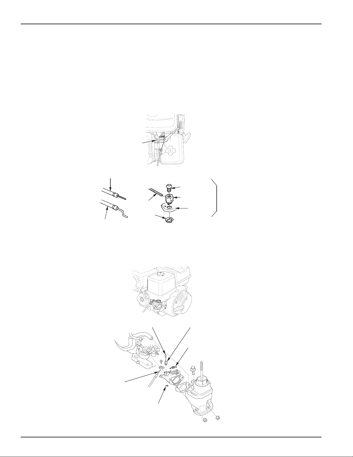
Flexible wire core
mounting
Solid wire core
mounting
WIRE
5mm
CIRCLIP
4 mm SCREW
WIRE HOLDER
THROTTLE
LEVER
OPTIONAL
THROTTLE LEVER
FRICTION NUT
WIRE HOLDER
4 mm SCREW
WIRE
5 mm CIRCLIP
SPRING
Carburetor Controls
Types of cable:
Two types can be used, flexible wire core or solid wire.
Installation:
The throttle and choke control levers are provided with holes for optional cable attachment. The following illustrations
show installation examples for a solid wire cable and for a flexible, braided wire cable. If using a flexible, braided wire
cable, add a return spring as shown. It is necessary to loosen the throttle lever friction nut when operating the throttle
with a remote-mounted control.
Remote Control Throttle
Remote Control Choke.
8 © 2010 American Honda Motor Co., Inc — All Rights Reserved
Page 11
GX240 • GX270 • GX340 • GX390 (UT2/RT2) Technical Manual
EXHAUST SYSTEM
Recommended Muffler
The recommended muffler and exhaust pipe are matched to the engine in terms of emissions performance, exhaust
backpressure, sound level, and durability.
Consider the following:
• Discharge the exhaust gas directly to the open air. Do not install flammable parts or any parts with poor heat
resistance properties around the exhaust system or near the discharge port.
• The exhaust gas must not enter the cooling-air intake port. Be especially careful when using the exhaust deflector
to change the discharge direction.
• The muffler and exhaust pipe become very hot during operation and remain hot after the engine has been shut off.
Install the muffler and exhaust pipe so the fuel system and other heat-sensitive components are isolated from the
exhaust heat.
Fabricated Exhaust Systems
The muffler type and the shape and length of the exhaust pipe(s) affect emissions performance and engine power. If
you use a muffler other than a recommended Honda muffler, observe the following precautions to maintain the
engine’s peak performance:
• The shape (bends and elbows) of the exhaust pipe can affect exhaust backpressure. If exhaust backpressure is
excessive, it can affect emissions performance and/or cause detonation.
• The exhaust pipe inside diameter must be the same size as the exhaust port diameter.There must be no gap
between the port inside diameter and the exhaust pipe ID.
• The exhaust backpressure increases if the diameter is less than specified. If the diameter is larger than specified,
the effective width of the exhaust gasket is reduced which could cause an exhaust leak.
• When the exhaust pipes are connected together before the muffler, make sure that the exhaust pipe length is as
short as possible to reduce backpressure.
• Muffler volume and design will affect exhaust backpressure. Increase the volume of the muffler if exhaust
backpressure is higher than specified.
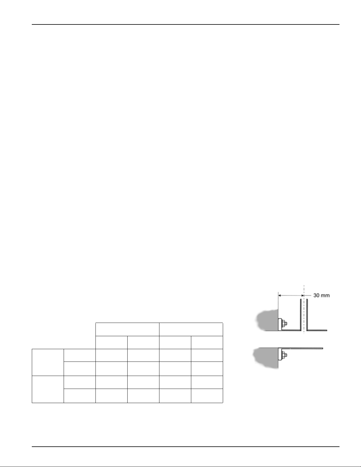
Exhaust Back Pressure Measurement
Measure the exhaust back pressure at the exhaust pipe with the engine under
continuous load (WOT), 30 mm (1.2 in) from the exhaust pipe mounting flange
as shown (make sure the test nipple does not extend beyond the inner wall of
the exhaust pipe).
3000 rpm 3600 rpm
Min. Max Min. Max
GX240
GX270
kPa 4.2 9.0 4.9 11.0
mmH
O 428 918 500 1122
2
GX340
GX390
© 2010 American Honda Motor Co., Inc — All Rights Reserved 9
kPa 4.6 10.5 6 12.5
mmH
O 469 1071 612 1275
2
Page 12
GX240 • GX270 • GX340 • GX390 (UT2/RT2) Technical Manual
Rigid Engine Mount Muffler Installation.
The frame must be rigid to prevent cracking when the exhaust pipe and muffler are connected. The muffler should be
installed securely with bolts and nuts.
The muffler should be supported at two points (or more) using special rubber mounts designed for muffler support
applications.
Check to see muffler vibration does not increase at any given engine speed, causing an abnormal increase in
resonance.
Rubber Engine Mount Muffler Installation
A flexible pipe should be used between the muffler and exhaust pipe when the engine is mounted to the engine bed
with rubber mounts. The flexible pipe ID must be the same as the exhaust pipe OD or larger.
The muffler should be supported at two points (or more) and should be installed securely with bolts and nuts to prevent
muffler cracking from vibration during starting and stopping.
Check to see muffler vibration does not increase at any given engine speed, causing an abnormal increase in
resonance.
ENGINE MOUNTING
Use an engine bed or frame with enough rigidity to allow maximum durability
of the engine and attachment installation.
The engine must not wobble on the engine bed. Use an engine bed or frame
that provides a flat surface for the engine to be mounted on. If there is a gap
between the engine and the engine bed, the engine-mounting surface may
be damaged.
Inclination
Horizontal mounting and operation of the engine is recommended. If the
engine must be operated on a slope, the incline position of the engine must
not exceed 20° in any direction.
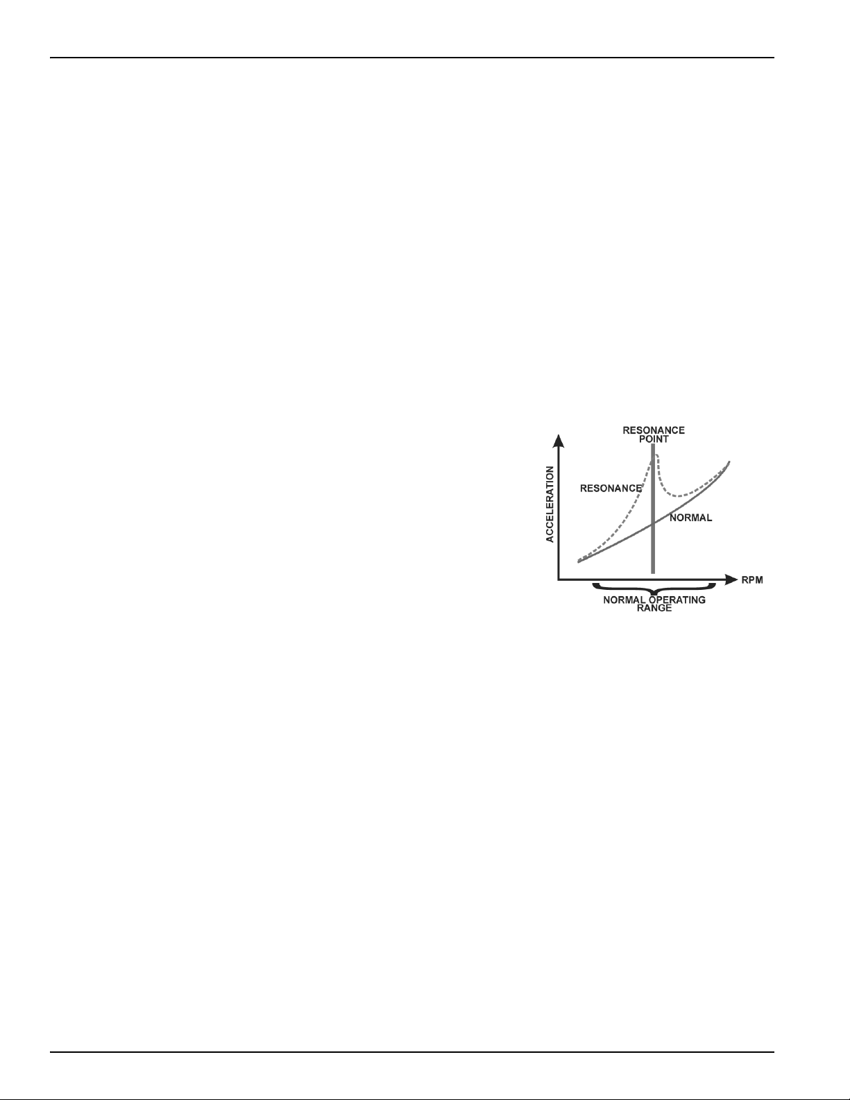
Resonance Check
There must be no resonance when the engine and attachment are operated within the designated speed range. Slowly
raise the engine speed from idle to maximum and check for resonance at any engine speed.
General Methods for Preventing Resonance
When engine accessories or a part of the attachment is resonating, increase the rigidity of the resonating part to bring
the resonance point higher than the working engine speed range.
• Increase the rigidity of the engine bed and frame to bring the resonance point higher than the working engine
speed range.
• Install the muffler on the engine body, using a rigid stay to prevent resonance of the muffler when the engine speed
is within the specific operating speed range.
10 © 2010 American Honda Motor Co., Inc — All Rights Reserved
Page 13
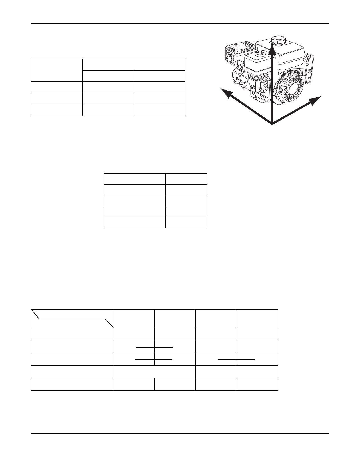
GX240 • GX270 • GX340 • GX390 (UT2/RT2) Technical Manual
HORIZONTAL
VERTICAL
LATERAL
Engine Acceleration/Vibration
Using a vibration meter, measure the vibration amplitude at the base
on three axis (vertical, lateral and horizontal).
Direction Allowable G value
(Peak) (RMS)
Vertical 10 (98 m/s
Horizontal 5.9 (58 m/s
Lateral 6.9 (68 m/s
2
)6.9 (68 m/s
2
)4.2 (41 m/s
2
)4.9 (48 m/s
2
)
2
)
2
)
ELECTRICAL SYSTEM
Battery
Use a 12 V battery with a minimum capacity of 24AH.
Fuse
Recommended fuse size:
Charging system (A) Fuse (A)
1.0 5
3.0
10.0
18.0 25
15
Battery Cables
Select battery cables to avoid greater than 0.5 volt drop in the cable during starter motor operation.
Battery cable size and length: (Gauge x Length)
Positive cable: AWG No. 4 x 1.5 m (5.0 ft) maximum
Negative cable: AWG No. 4 x 2.3 m (7.5 ft) maximum
Engine Switch
Electric start
Use a three-position engine switch with continuity between its terminals as shown.
Wire Color
Switch Position
OFF
ON {{
EXT+
(Red)
EXT –
(Black)
ST
(Black/White)
BAT
(White)
START {{{{
Vdc/A (rated) AC300V, 220mA (PEAK) 12/15A
Dia. (recommended) AV0.5 AV0.5 AV2.0* AV0.75
* In combination with 1A/3A/10A charge coil, AV1.25 is acceptable.
AV0.5 = Automotive Vinyl, 0.5 mm
2
cross-sectional area
Do not run the starter motor for more than 5 seconds at a time. Always allow resting for 10 seconds before each
starting attempt.
© 2010 American Honda Motor Co., Inc — All Rights Reserved 11
Page 14
GX240 • GX270 • GX340 • GX390 (UT2/RT2) Technical Manual
Manual start
Use a two-position engine switch with continuity between its terminals as shown.
Wire Color
Switch Position
OFF
ON {{
EXT+
(Red)
EXT –
(Black)
Charging Coil Selection
Four types of coils are available:
Coil Output (A) Regulated RPM
1A 0.9 No
3A 2.7 No
10A 9.5 Yes
18A 17.0 Yes
The 1A and 3A coils are only suitable for recharging a starting battery. Use the 10A or 18A coils when powering
accessories.
3,600
Lamp Coil Kit (optional)
Three types of lamp coils are available: 6v –25w, 12v –15w, 12v –25w. Two coils can be installed in parallel to provide
12V-50W, if no charging coils are applied. Use parallel connector (No. 32105-ZE1-000) to connect two coils in parallel.
A single coil (12v-25w) can be used in combination with the 3A charge coil as required.
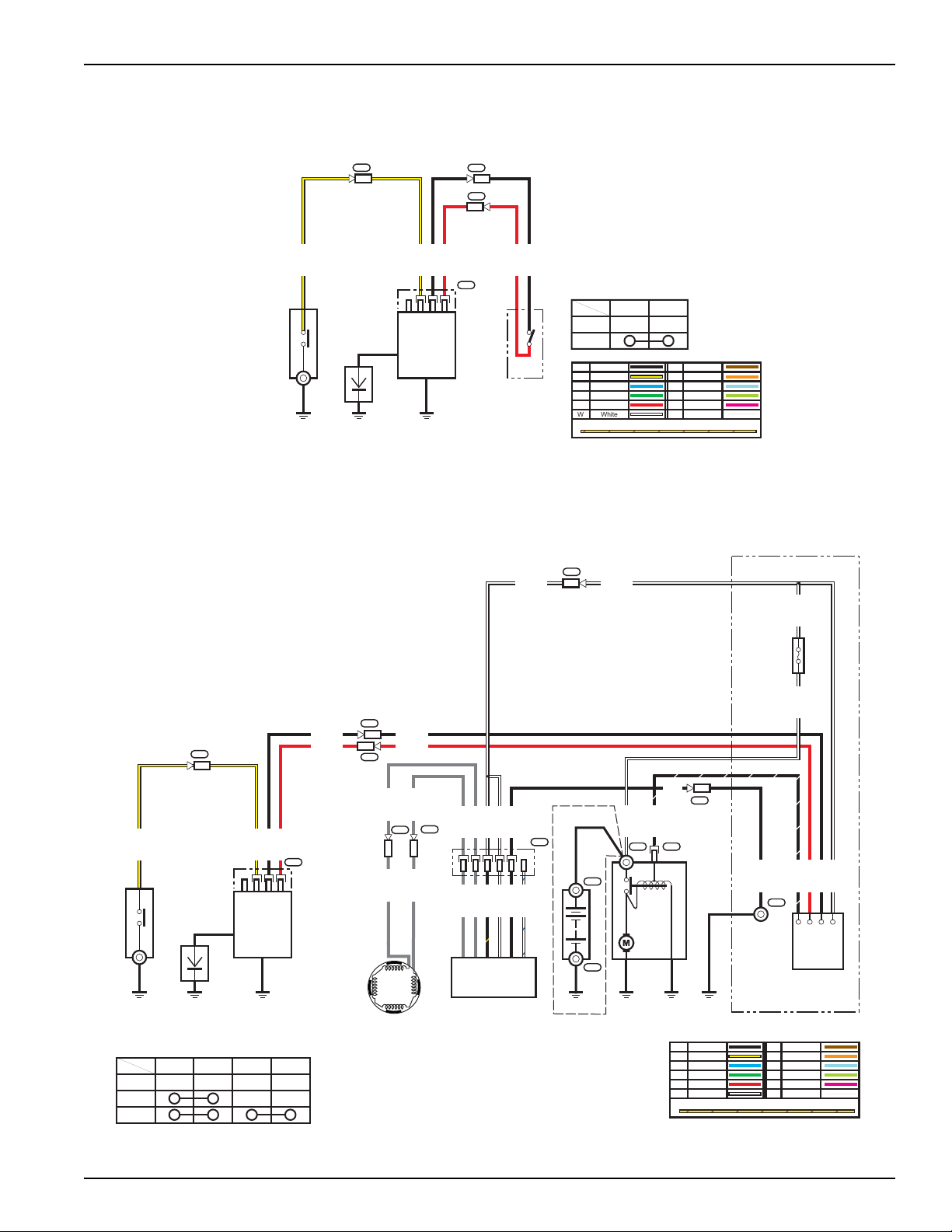
Oil Alert® System (optional)
The Oil Alert System uses a float type switch located inside the crankcase. When the engine oil level falls below a safe
operating level, the float falls and the circuit is completed through the control box, grounding the primary side of the
ignition coil. The Oil Alert System is only recommended for use on equipment that is stationary while operating.
Wiring Precautions
• Connect the battery positive (+) cable to the positive terminal of the starter solenoid.
• Connect the battery negative (–) cable to the engine crankcase or engine frame mounting bolt.
• Do not route the battery cables on or near any hot, moving, or rotating parts, or sharp edges. Keep the battery
cables and electrical wires away from the fuel line.
• Protect positive electrical connections with a cover or insulation.
12 © 2010 American Honda Motor Co., Inc — All Rights Reserved
Page 15
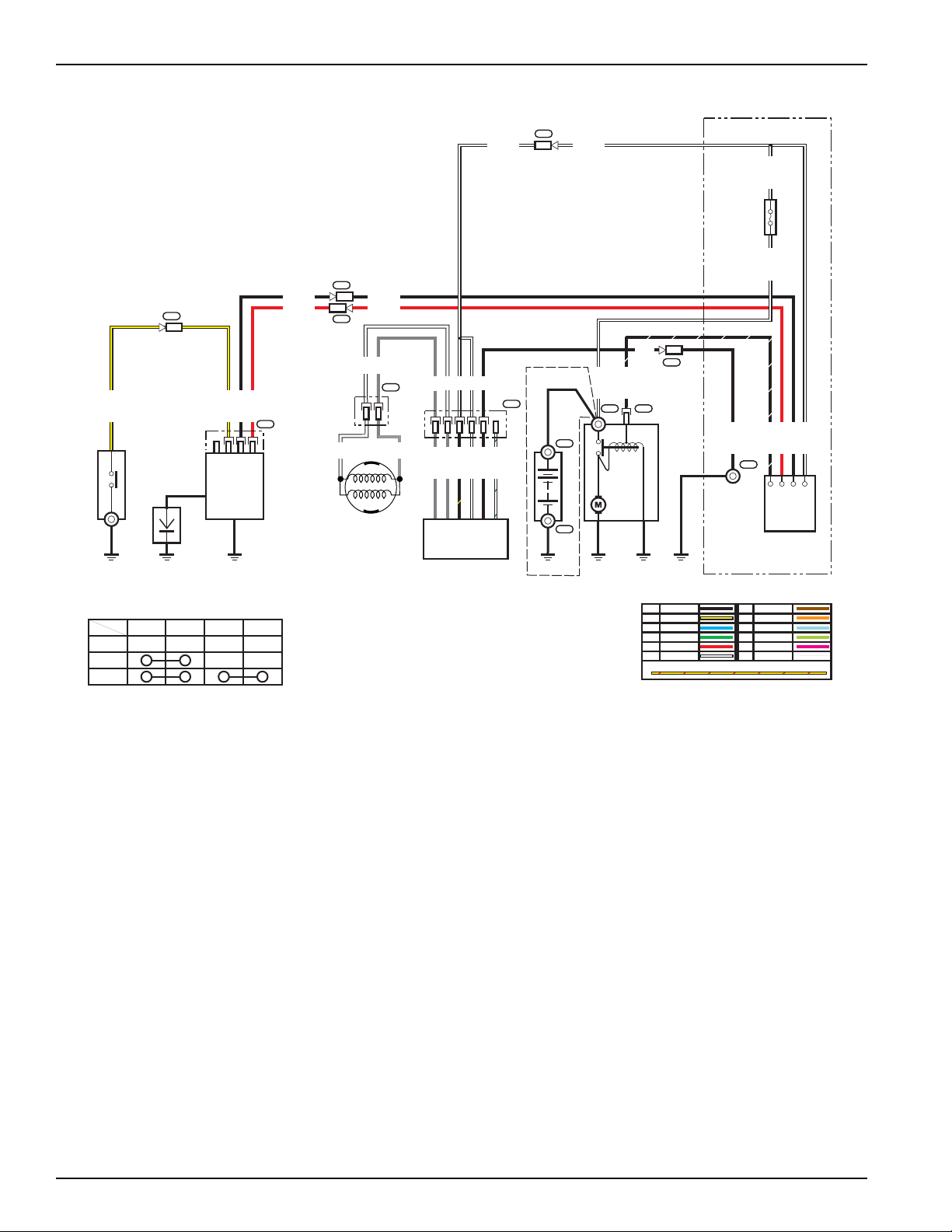
GX240 • GX270 • GX340 • GX390 (UT2/RT2) Technical Manual
LED
OIL_ALT
EXT ( - )
EXT ( + )
R
Bl
R
Bl
Y
Y
C2
C1
1
4 3 1 2
C3
IGNITION
COIL
SPARK
PLUG
OIL LEVEL
SWITCH
ENGINE STOP
SWITCH
Bl Black
Y Yellow
Bu Blue
G Green
R Red
W White
Br Brown
O Orange
Lb Light blue
Lg Light green
P Pink
Gr Gray
TWO COLORED WIRE (EXAMPLE:YELLOW/RED)
EXT ( + ) EXT ( - )
OFF
ON
ENGINE STOP SWITCH
LED
OIL_ALT
EXT ( - )
EXT ( + )
ST
EXT ( + )
EXT ( - )
BAT
( Bl/W )
( W )
R
Gr
Gr
Gr
Gr
W
W
Bl
Gr
Gr
Gr
Gr
Bl/Y
W
Bl
W/Bu
Bl
Y
Y
Bl/W
( Bl )
R
Bl
W
W W
(W)
R
Bl
(W)
R
Bl
Bl
3
C10
C2
C1
C9
C8
T2
T3
1
4312
C3
C11
C4T1
T4
CONTROL BOX
COMBINATION
SWITCH
STARTER MOTORBATTERY
CHARGE
COIL
REGULATOR/
RECTIFIER
IGNITION
COIL
SPARK
PLUG
OIL LEVEL
SWITCH
Bl Black
Y Yellow
Bu Blue
G Green
RRed
W White
Br Brown
O Orange
Lb Light blue
Lg Light green
P Pink
Gr Gray
TWO COLORED WIRE (EXAMPLE:YELLOW/RED)
EXT ( + ) EXT ( - ) ST BAT
OFF
ON
START
461235
COMBINATION
SWITCH
MAIN FUSE
CHARGE
COIL
FLYWHEEL
WIRING DIAGRAMS
No Charge Coil Models
Electric Start Models
18A Charging System
© 2010 American Honda Motor Co., Inc — All Rights Reserved 13
Page 16
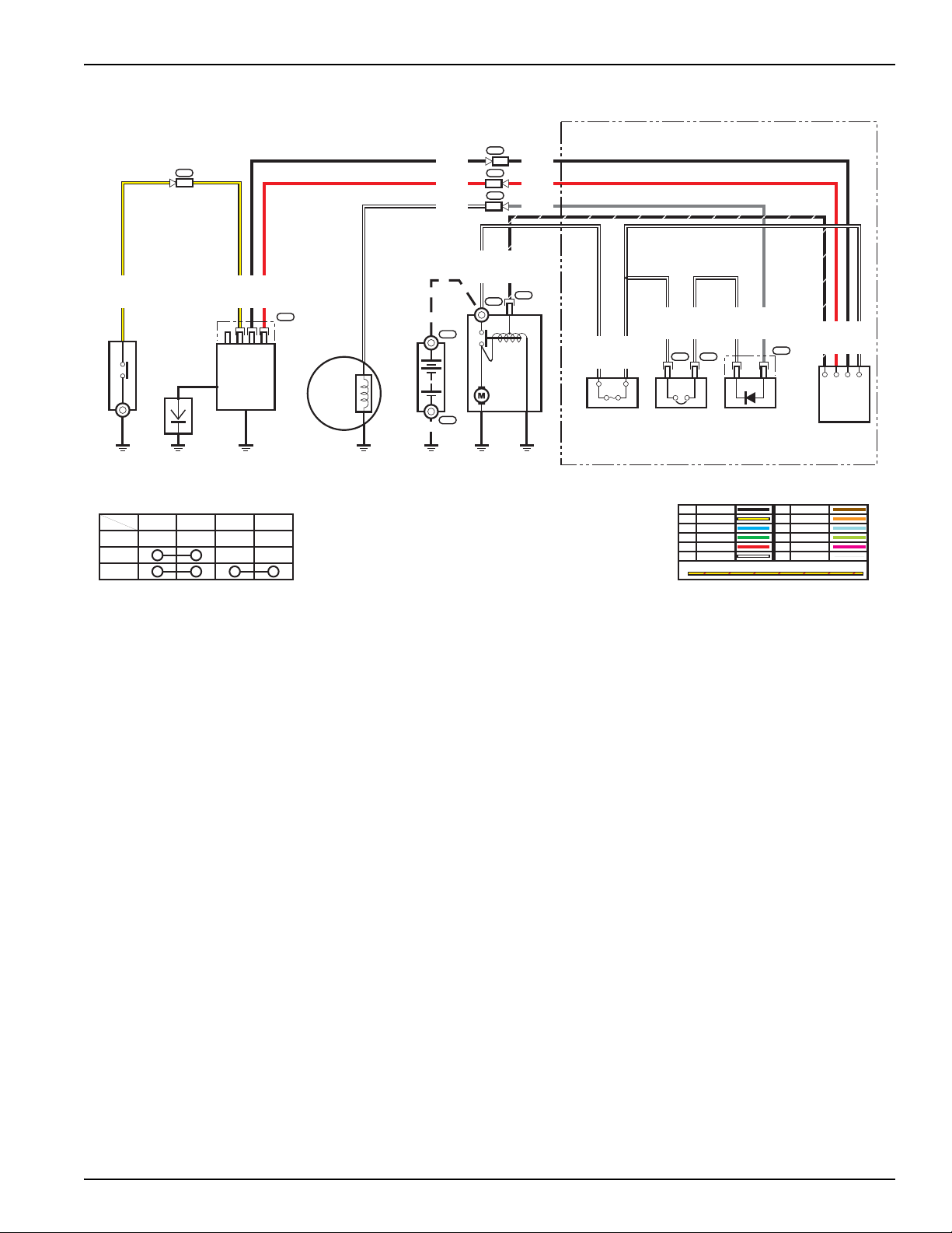
10A Charging System
LED
OIL_ALT
EXT ( - )
EXT ( + )
ST
EXT ( + )
EXT ( - )
BAT
( Bl/W )
( W )
R
W
WGrW
Bl
Gr
Gr
Bl/Y
W
Bl
W/Bu
Bl
Y
Y
Bl/W
( Bl )
R
Bl
W
W W
(W)
R
Bl
(W)
R
Bl
Bl
3
C10
C2
C1
T2
T3
1
4312
C3
C11
C4T1
T4
CONTROL BOX
COMBINATION
SWITCH
STARTER MOTORBATTERY
REGULATOR/
RECTIFIER
IGNITION
COIL
SPARK
PLUG
OIL LEVEL
SWITCH
Bl Black
Y Yellow
Bu Blue
G Green
RRed
W White
Br Brown
O Orange
Lb Light blue
Lg Light green
P Pink
Gr Gray
TWO COLORED WIRE (EXAMPLE:YELLOW/RED)
EXT ( + ) EXT ( - ) ST BAT
OFF
ON
START
461235
COMBINATION
SWITCH
MAIN FUSE
4
12
Gr
W
Gr
W
CHARGE COIL
FLYWHEEL
GX240 • GX270 • GX340 • GX390 (UT2/RT2) Technical Manual
14 © 2010 American Honda Motor Co., Inc — All Rights Reserved
Page 17
GX240 • GX270 • GX340 • GX390 (UT2/RT2) Technical Manual
LED
OIL_ALT
EXT ( - )
EXT ( + )
ST
EXT ( + )
EXT ( - )
BAT
( Bl/W )
( W )
R
Bl
Y
( Y )
( W )
( W )
( W )
( W )
( W )
( Gr )
( Bl/W )
( R )
( Bl )
( W )
W
( R )
( Bl )
Gr
( R )
( Bl )
C6
C4
C5
C2
C1
T1
T2
T3
1
4 3 1 2
2 1
C3
C7
2
CONTROL BOX
COMBINATION
SWITCH
SILICON
RECTIFIER
CIRCUIT
PROTECTOR
MAIN FUSE
STARTER MOTOR BATTERY CHARGE
COIL
IGNITION
COIL
SPARK
PLUG
OIL LEVEL
SWITCH
Bl Black
Y Yellow
Bu Blue
G Green
R Red
W White
Br Brown
O Orange
Lb Light blue
Lg Light green
P Pink
Gr Gray
TWO COLORED WIRE (EXAMPLE:YELLOW/RED)
EXT ( + ) EXT ( - ) ST BAT
OFF
ON
START
COMBINATION
SWITCH
1A/3A Charging System
© 2010 American Honda Motor Co., Inc — All Rights Reserved 15
Page 18

GX240 • GX270 • GX340 • GX390 (UT2/RT2) Technical Manual
Axial
Load =0
CRANKSHAFT
0 mm
MAXIMUM OVERHANG
PULLEY
0 40 60 80 100 120
1000
2000
3000
4000
5000
6000
(N)
DOWNWARD PULL RANGE
1200
1000
800
600
400
200
0
(lbf)
DOWNWARD PULL RANGE ONLY
ENGINE PTO
Distance from engine side cover
to center line of drive pulley
(mm)
STATIC RADIAL LOAD
Keep static radial load below the
pull limit indicated in the chart on the left.
POWER TRANSMISSION
V-Belt Connections
Be sure there is no static axial load applied
to the crankshaft.
Install the pulley as close to the base of
the PTO shaft as possible. When installing
the pulley at the end of the PTO shaft, be
sure there is no overhang.
Before securing the engine and attachment to the engine bed, verify that the V-groove of the engine pulley and
attachment pulley are aligned and that the engine PTO shaft and attachment driven shaft are parallel.
When high load, high inertia exists, we recommend using a tapered shaft pulley for added security.
The frame or engine bed must be rigid enough to prevent belt resonance in the working speed range of the engine.
Size the pulleys so they do not cause resonance of the belt(s).
16 © 2010 American Honda Motor Co., Inc — All Rights Reserved
Page 19

GX240 • GX270 • GX340 • GX390 (UT2/RT2) Technical Manual
To reduce resonance, install a stay between the engine and attachment as shown below.
Starting Performance
The engine must be able to start with the attachment at the lowest recommended ambient temperature.
If the starting load of the attachment is too large when operating the starter motor, provide a clutch so you can separate
the load from the engine when operating the starter.
Due to changes in oil viscosity, there will be an increased drag in attachments such as hydraulic pumps or gear cases
as temperature drops. Start the engine with the ambient temperature at the lowest temperature recommended for
operating the attachment. Verify that the attachment, as well as the engine, can start and operate normally.
Select the proper oil viscosity for the attachment according to the attachment’s working temperature.
Minimum engine cranking voltage 10.2 Vdc
Minimum engine cranking rpm 474 rpm
Maximum engine cranking amperage 50 A
© 2010 American Honda Motor Co., Inc — All Rights Reserved 17
Page 20

GX240 • GX270 • GX340 • GX390 (UT2/RT2) Technical Manual
RECOIL STARTER
ENGINE CONTROL TYPES
AIR CLEANER
MUFFLER
EXCEPT ELECTRIC
STARTER TYPES
ENGINE SWITCH
ENGINE SWITCH
CHOKE LEVER
PURGE
PORT
FUEL
VALVE LEVER
ENGINE SWITCH
ELECTRIC STARTER TYPES
STARTER GRIP
CHOKE ROD
(applicable types)
ENGINE OIL DRAIN
VALVE COVER
SPARK PLUG
SPARK ARRESTER
INSTALLATION CONSIDERATIONS
Maintenance Points Accessibility
When the engine is installed in an enclosure, provide an access panel or use an engine enclosure that can be opened
and closed easily. See also Serviceability page 40.
The emission control information label on the engine must be visible when the engine is installed in the equipment. If it
is not visible by removing a panel, lifting a hood, or other means not using tools, you must attach a supplemental
(duplicate) label. See 40 CFR part 90.114 (http://ecfr.gpoaccess.gov/cgi/t/text/textidx?c=ecfr&rgn=div5&view=text&node=40:20.0.1.1.4&idno=40#40:20.0.1.1.4.2.1.14). Contact your Engine Distributor
for supplemental labels.
Left Side
Recoil
Air cleaner cover
Engine oil drain
(Crankcases tapped for
NPT drain extensions are
available.)
Spark plug
Valve cover
Choke lever
Throttle lever
Spark Arrester
Engine switch
Emission label
18 © 2010 American Honda Motor Co., Inc — All Rights Reserved
Page 21

GX240 • GX270 • GX340 • GX390 (UT2/RT2) Technical Manual
FUEL FILLER CAP
FUEL TANK
OIL DRAIN PLUG
ELECTRIC STARTER
(applicable types)
OIL FILLER CAP/DIPSTICK
ELECTRICAL
CONNECTIONS
Right Side
Fuel cap
Oil filler/cap dipstick
Engine oil drain plug
Electric starter
Electrical connections
© 2010 American Honda Motor Co., Inc — All Rights Reserved 19
Page 22

DIMENSIONAL DRAWINGS
Unit: mm (in)
150 (5.9)
With control box type: 462 (18.2)
99 (3.9)
134 (5.3)
278 (10.9)
92 (3.6)
1
3
3
.
5
(
5
.
2
6
)
116 (4.6)
192 (7.6)
1
3
(
0
.
5
)
3
4
.
5
(
1
.
3
6
)
9
6
(
3
.
8
)
105 (4.1)
195.5 (7.70)
Without control box type: 428 (16.9)
CRANKSHAFT (P. T. O.)
CONTROL BOX
STARTER MOTOR
(If equipped)
(If equipped)
4
1
8
(
1
6
.
5
)
G
X
2
4
0
U
2
/
U
T
2
:
4
2
2
(
1
6
.
6
)
G
X
2
4
0
R
2
/
R
T
2
:
3
0
3
(
1
1
.
9
)
* S:355 (14.0)
* P/Q:380 (15.0)
* E:360 (14.2)
GX240UT2 * V:400 (15.7)
* W:370 (14.6)
GX240RT2 *V:420 (16.5)
GX240-270
Without Reduction
GX240 • GX270 • GX340 • GX390 (UT2/RT2) Technical Manual
20 © 2010 American Honda Motor Co., Inc — All Rights Reserved
Page 23

GX240 • GX270 • GX340 • GX390 (UT2/RT2) Technical Manual
Unit: mm (in)
* H:425 (16.7)
150 (5.9)
* R:187.2 (7.37)
1
3
3
.
5
(
5
.
2
6
)
105 (4.1)
195.5 (7.70)
* L/H:68.1 (2.68)
P. T. O. SHAFT
* R:440 (17.3)
REDUCTION UNIT
* R:188.5 (7.42)
9
9
(
3
.
9
)
1
3
4
(
5
.
3
)
With control box type: 462 (18.2)
Without control box type: 428 (16.9)
116 (4.6)
192 (7.6)
4
1
8
(
1
6
.
5
)
1
3
(
0
.
5
)
3
4
.
5
(
1
.
3
6
)
9
6
(
3
.
8
)
* R:90.8 (3.57)
* L/H:209.9 (8.26)
CONTROL BOX
STARTER
MOTOR
(If equipped)
(If equipped)
* L:405 (15.9)
* L/H:140.3 (5.52)
G
X
2
4
0
U
2
/
U
T
2
:
4
2
2
(
1
6
.
6
)
With Reduction
© 2010 American Honda Motor Co., Inc — All Rights Reserved 21
Page 24

Without Fuel Tank
134 (5.28)99 (3.90)
290.8 (11.45)
361.5 (14.23)
195.5 (7.70)
105 (4.13)
103 (4.06)
M8X1.25 DEPTH 18 (0.71)
DEPTH 4 (0.16 )
DEPTH 4.5 (0.18)
(6PLCS)
184.3 (7.26)
294.6 (11.60)
45°
45°
30°
30°
70 (2.76)
311 (12.24)
CONTROL BOX
STARTER MOTOR
Unit: mm (in)
GX240 • GX270 • GX340 • GX390 (UT2/RT2) Technical Manual
22 © 2010 American Honda Motor Co., Inc — All Rights Reserved
Page 25

GX240 • GX270 • GX340 • GX390 (UT2/RT2) Technical Manual
307 (11.17)
57.5 (2.26)
22 (0.87)
101.8 (4.01)
96 (3.78)
34.5 (1.36)
13 (0.51)
OIL DRAIN
EVAP PURGE JOINT
107.2 (4.22)
0.9 (0.04)
153 (6.02)
432 (17.01)
150.1 (5.91)
133.8 (5.27)
135.2 (5.32)
CONTROL BOX
STARTER MOTOR
Unit: mm (in)
© 2010 American Honda Motor Co., Inc — All Rights Reserved 23
Page 26

GX340-390
Unit: mm (in)
* S:380 (15.0)
158.7 (6.25)
* P/Q:405 (15.9)
* V:425 (16.7)
With control box type: 498.6 (19.63)
4
4
7
(
1
7
.
6
)
9
8
(
3
.
9
)
1
2
1
.
8
(
4
.
8
0
)
301.3 (11.86)
100 (3.9)
1
3
3
.
5
(
5
.
2
6
)
141.5 (5.57) 200.6 (7.90)
1
7
(
0
.
7
)
2
7
(
1
.
1
)
1
0
3
(
4
.
1
)
105 (4.1)
195.5 (7.70)
Without control box type: 460 (18.1)
CRANKSHAFT (P. T. O.)
CONTROL BOX
STARTER MOTOR
(If equipped)
(If equipped)
E
X
C
E
P
T
G
X
3
9
0
U
T
2
:
4
4
8
(
1
7
.
6
)
Without Reduction
GX240 • GX270 • GX340 • GX390 (UT2/RT2) Technical Manual
24 © 2010 American Honda Motor Co., Inc — All Rights Reserved
Page 27

GX240 • GX270 • GX340 • GX390 (UT2/RT2) Technical Manual
Unit: mm (in)
* L:440 (17.3)
158.7 (6.25)
* H:452 (17.8)
460 (18.1)
4
4
7
(
1
7
.
6
)
233.2 (9.18)
1
3
3
.
5
(
5
.
2
6
)
141.5 (5.57) 200.6 (7.9)
1
7
(
0
.
7
)
2
7
(
1
.
1
)
1
0
3
(
4
.
1
)
105 (4.1)
195.5 (7.70)
REDUCTION UNIT
68.1 (2.68)
P. T. O. SHAFT
155 (6.1)
With Reduction Unit
© 2010 American Honda Motor Co., Inc — All Rights Reserved 25
Page 28

Without Fuel Tank
CONTROL BOX
STARTER MOTOR
121.8 (4.80)
98 (3.86)
328 (12.91)
399.5 (15.72) GX340R2 EDN2, EDE2
423.5 (16.67) GX390R2 EDT6, EDS6
103 (4.06)
105 (4.13)
195.5 (7.70)
321 (12.64)
197.3 (7.77) 312 (12.28)
OIL FILLER CAP
70 (2.76)
OIL FILLER CAP
Unit: mm (in)
GX240 • GX270 • GX340 • GX390 (UT2/RT2) Technical Manual
26 © 2010 American Honda Motor Co., Inc — All Rights Reserved
Page 29

GX240 • GX270 • GX340 • GX390 (UT2/RT2) Technical Manual
0.4 (0.02)
153 (6.02)
26 (1.02)
GX340R2 EDN2, EDE2
321 (12.63)
345 (13.58)
GX390R2 EDT6, EDS6
EVAPORATIVE
PURGE JOINT
100.2 (3.94)
OIL DRAIN
27 (1.06)
103 (4.06)
104.6 (4.12)
100 (3.94)
73 (2.87)
17 (0.67)
457 (18.0)
158.7 (6.25)
CONTROL BOX
STARTER MOTOR
140.8 (5.54)128.2 (5.05)
Unit: mm (in)
© 2010 American Honda Motor Co., Inc — All Rights Reserved 27
Page 30

PTO DIMENSIONAL DRAWINGS
Unit: mm (in)
45° 45°
103 (4.1)
7
0
(
2
.
8
)
85.7 (3.37)
P
.
D
.
1
2
7
(
5
.
0
0
)
Φ
2
5
.
3
7
4
-
2
5
.
4
0
0
(
Φ
0
.
9
9
9
0
-
1
.
0
0
0
0
)
16 (0.6)
62.1 (2.45)
REDUCTION UNIT
P. T. O. SHAFT
6.31- 6.36
(0.248-0.250)
80 (3.20)
63 (2.5)
2
1
.
6
9
-
2
1
.
8
2
(
0
.
8
5
4
-
0
.
8
5
9
)
M8 x 1.25
(4 PLACES)
M8 x 1.25
(2 PLACES)
Unit: mm (in)
45° 45°
103 (4.1)
7
0
(
2
.
8
)
M8 x 1.25
7.00 - 7.05
(0.276 -0.278)
64.8 (2.55)
P
.
D
.
1
2
7
(
5
.
0
0
)
Φ
2
4
.
9
7
2
-
2
4
.
9
9
3
(
0
.
9
8
3
1
-
0
.
9
8
4
0
)
16 (0.6)
68.1 (2.68)
60.0 (2.36)
42 (1.7)
REDUCTION UNIT
P. T. O. SHAFT
M8 x 1.25
(2 PLACES)
M8 x 1.25
(4 PLACES)
2
0
.
9
-
2
1
.
0
(
0
.
8
2
-
0
.
8
3
)
28 (1.1)
H Type (with reduction)
GX240 • GX270 • GX340 • GX390 (UT2/RT2) Technical Manual
L Type (with reduction)
28 © 2010 American Honda Motor Co., Inc — All Rights Reserved
Page 31

GX240 • GX270 • GX340 • GX390 (UT2/RT2) Technical Manual
Unit: mm (in)
30°
30°
45°
45°
103 (4.1)
7
0
(
2
.
8
)
89 (3.5)
Φ
2
5
.
3
7
5
-
2
5
.
4
0
0
(
Φ
0
.
9
9
9
0
-
1
.
0
0
0
0
)
14NF2 Thread R. H.
26-27
(1.0-1.1)
72.5 (2.85)
P
.
D
.
1
6
5
.
1
(
6
.
5
0
)
P
.
D
.
1
2
7
(
5
.
0
0
)
Φ
1
1
0
.
0
0
-
1
1
0
.
0
5
(
Φ
4
.
3
3
0
7
-
4
.
3
3
2
7
)
5/16-24UNF-2B
(2 PLACES)
5/16-24UNF-2B
(4 PLACES)
3/8-16UNC-2B
(4 PLACES)
CRANKSHAFT (P. T. O.)
Unit: mm (in)
30°
30°
45°
45°
103 (4.1)
7
0
(
2
.
8
)
88.5 (3.48)
56 (2.2)
Φ
2
5
.
3
7
5
-
2
5
.
4
0
0
(
Φ
0
.
9
9
9
0
-
1
.
0
0
0
0
)
3/8 - 24UNF - 2B TAP
28 (1.1)
72.2 (2.84)
P
.
D
.
1
6
5
.
1
(
6
.
5
0
)
P
.
D
.
1
2
7
(
5
.
0
0
)
6.3 - 6.35
(0.2480 - 0.2500)
2
1
.
6
9
-
2
1
.
8
2
(
0
.
8
5
3
9
-
0
.
8
5
9
1
)
CRANKSHAFT (P. T. O.)
Φ
1
1
0
.
0
0
-
1
1
0
.
0
5
(
Φ
4
.
3
3
1
-
4
.
3
3
3
)
5/16-24UNF-2B
(2 PLACES)
5/16-24UNF-2B
(4 PLACES)
3/8-16UNC-2B
(4 PLACES)
P Type
Q Type*
© 2010 American Honda Motor Co., Inc — All Rights Reserved 29
Page 32

S Type
Unit: mm (in)
30°
30°
45°
45°
103 (4.1)
7
0
(
2
.
8
)
63 (2.5)
41 (1.6)
Φ
2
4
.
9
4
7
-
2
4
.
9
8
0
(
Φ
0
.
9
8
2
2
-
0
.
9
8
3
5
)
M8-1.25
28 (1.1)
60 (2.4)
P
.
D
.
1
6
5
.
1
(
6
.
5
0
)
P
.
D
.
1
2
7
(
5
.
0
0
)
7.00 - 7.03
(0.276 - 0.277)
2
0
.
9
-
2
1
.
0
(
0
.
8
2
-
0
.
8
3
)
Φ
1
1
0
.
0
0
-
1
1
0
.
0
5
(
Φ
4
.
3
3
1
-
4
.
3
3
3
)
SNC TYPE:
5/16-24UNF-2B
TAP (2 PLACES)
SNC TYPE:
3/8-16UNC-2B
TAP (4 PLACES)
CRANKSHAFT (P. T. O.)
SM32 TYPE:
M8 x 1.25
(2 PLACES)
SM32 TYPE:
Φ8.5 (Φ0.33)
(4 PLACES)
SNC TYPE:
5/16-24UNF-2B
TAP
(4 PLACES)
SM32 TYPE:
M8 x 1.25
(4 PLACES)
Unit: mm (in)
30°
30°
45°
45°
103 (4.1)
7
0
(
2
.
8
)
105.5 (4.15)
46.5 (1.83)
2
2
.
1
3
6
-
2
2
.
1
6
1
(
Φ
0
.
8
7
1
5
-
0
.
8
7
2
4
)
5/16 - 24UNF - 2B TAP
18 (0.7)
75.5 (2.97)
P
.
D
.
1
6
5
.
1
(
6
.
5
0
)
P
.
D
.
1
2
7
(
5
.
0
0
)
Φ
1
1
0
.
0
0
-
1
1
0
.
0
5
(
Φ
4
.
3
3
1
-
4
.
3
3
3
)
CRANKSHAFT (P. T. O.)
5/16-24UNF-2B
(2 PLACES)
5/16-24UNF-2B
(4 PLACES)
3/8-16UNC-2B
(4 PLACES)
GX240 • GX270 • GX340 • GX390 (UT2/RT2) Technical Manual
V Type
30 © 2010 American Honda Motor Co., Inc — All Rights Reserved
Page 33

GX240 • GX270 • GX340 • GX390 (UT2/RT2) Technical Manual
Unit: mm (in)
80 (3.1)
75 (3.0)
15.5 (0.61)
30°
30°
45°
45°
P
.
D
.
1
6
5
.
1
(
6
.
5
0
)
P
.
D
.
1
1
3
.
1
(
4
.
4
5
)
7
0
(
2
.
8
)
Φ7.15(Φ0.281)
(2 PLACES)
CRANKSHAFT (P. T. O.)
M8 x 1.25
(4 PLACES)
Φ8.51(Φ0.335)
(4 PLACES)
Φ
8
9
(
Φ
3
.
5
)
103 (4.1)
M
2
0
x
1
.
5
55 (2.2)
W Type
© 2010 American Honda Motor Co., Inc — All Rights Reserved 31
Page 34

GX240 • GX270 • GX340 • GX390 (UT2/RT2) Technical Manual
DIMENSIONS AND WEIGHTS
GX240
P.T.O. VARIATION
Model P.T.O. GX240R2 GX240RT2 GX240U2 GX240UT2
Overall
length
Overall
width
Overall
height
Dry weight E type 21.4 kg (47.2 lbs) - - -
Operating
weight
E type 360 mm (14.2 in) - - H type - - - 425 mm (16.7 in)
L type - - 405 mm (15.9 in) 405 mm (15.9 in)
P type - - - 380 mm (15.0 in)
Q type - - - 380 mm (15.0 in)
R type - - - 440 mm (17.3 in)
S type - - - 355 mm (14.0 in)
V type - 420 mm (16.5 in) - 400 mm (15.7 in)
W type - - - 370 mm (14.6 in)
E type 428 mm (16.9 in) - - H type - - - 428 mm (16.9 in)
L type - - 428 mm (16.9 in) 428 mm (16.9 in)
P type - - - 428 mm (16.9 in)
Q type - - - 428 mm (16.9 in)
R type - - - 428 mm (16.9 in)
S type - - - 428 mm (16.9 in)
V type - 428 mm (16.9 in) - 428 mm (16.9 in)
W type - - - 428 mm (16.9 in)
E type 303 mm (11.9 in) - - H type - - - 422 mm (16.6 in)
L type - - 422 mm (16.6 in) 422 mm (16.6 in)
P type - - - 422 mm (16.6 in)
Q type - - - 422 mm (16.6 in)
R type - - - 422 mm (16.6 in)
S type - - - 422 mm (16.6 in)
V type - 303 mm (11.9 in) - 422 mm (16.6 in)
W type - - - 422 mm (16.6 in)
H type - - - 26.5 kg (58.4 lbs)
L type - - 26.5 kg (58.4 lbs) 26.5 kg (58.4 lbs)
P type - - - 25.8 kg (56.9 lbs)
Q type - - - 25.8 kg (56.9 lbs)
R type - - - 30.1 kg (66.1 lbs)
S type - - - 25.8 kg (56.9 lbs)
V type - 21.4 kg (47.2 lbs) - 25.8 kg (56.9 lbs)
W type - - - 25.8 kg (56.9 lbs)
E type 26.1 kg (57.5 lbs) - - H type - - - 31.5 kg (69.4 lbs)
L type - - 31.5 kg (69.4 lbs) 31.5 kg (69.4 lbs)
P type - - - 30.5 kg (67.2 lbs)
Q type - - - 30.5 kg (67.2 lbs)
R type - - - 35.0 kg (77.2 lbs)
S type - - - 30.5 kg (67.2 lbs)
V type - 26.1 kg (57.5 lbs) - 30.5 kg (67.2 lbs)
W type - - - 30.5 kg (67.2 lbs)
32 © 2010 American Honda Motor Co., Inc — All Rights Reserved
Page 35

GX240 • GX270 • GX340 • GX390 (UT2/RT2) Technical Manual
EQUIPMENT VARIATION
Indicates the difference compared with values of P. T. O. variation above.
Variation No balancer type Cyclone air cleaner
Overall length difference----+ 20 mm (0.8 in)
Overall width difference - + 96 mm (3.8 in) - + 34 mm (1.3 in) -
Overall height difference----- 119 mm (4.7 in)
Dry weight difference - 0.9 kg (2.0 lbs) + 0.2 kg (0.4 lbs) + 2.5 kg (5.5 lbs) + 3.2 kg (7.1 lbs) - 4.4 kg (9.7 lbs)
Operating weight
difference
*1: No fuel tank, muffler, and low profile type air cleaner.
- 0.9 kg (2.0 lbs) + 0.2 kg (0.4 lbs) + 2.5 kg (5.5 lbs) + 3.2 kg (7.1 lbs) - 4.4 kg (9.7 lbs)
type
Starter motor type Control box type Low profile type *1
© 2010 American Honda Motor Co., Inc — All Rights Reserved 33
Page 36

GX240 • GX270 • GX340 • GX390 (UT2/RT2) Technical Manual
GX270
P.T.O. VARIATION
Model P.T.O. GX270UT2
Overall length E type 340 mm (13.4 in)
H type 425 mm (16.7 in)
P type
Q type
S type 355 mm (14.0 in)
V type 400 mm (15.7 in)
R type 440 mm (17.3 in)
Overall width E type
H type
P type
Q type
S type
V type
R type
Overall height E type
H type
P type
Q type
S type
V type
E type
Dry weight E type 25.0 kg (55.1 lbs)
H type 26.5 kg (58.4 lbs)
P type
Q type
S type
V type
R type 30.0 kg (66.1 lbs)
Operating
weight
E type 29.7 kg (65.5 lbs)
H type 31.5 kg (69.4 lbs)
P type
Q type
S type
V type
R type 35.0 kg (77.2 lbs)
380 mm (15.0 in)
428 mm (16.9 in)
422 mm (16.6 in)
25.8 kg (57.0 lbs)0
30.5 kg (67.0 lbs)
EQUIPMENT VARIATION
Indicates the difference compared with values shown in the table of P. T. O. variation on (page 28).
Variation No balancer type Cyclone air cleaner
Overall length difference----+ 20 mm (0.8 in)
Overall width difference - + 96 mm (3.8 in) - + 34 mm (1.3 in) -
Overall height difference----- 119 mm (4.7 in)
Dry weight difference - 0.9 kg (2.0 lbs) + 0.2 kg (0.4 lbs) + 2.5 kg (5.5 lbs) + 3.2 kg (7.1 lbs) - 4.4 kg (9.7 lbs)
Operating weight
difference
*1: No fuel tank, muffler, and low profile type air cleaner.
34 © 2010 American Honda Motor Co., Inc — All Rights Reserved
- 0.9 kg (2.0 lbs) + 0.2 kg (0.4 lbs) + 2.5 kg (5.5 lbs) + 3.2 kg (7.1 lbs) - 4.4 kg (9.7 lbs)
type
Starter motor type Control box type Low profile type *1
Page 37

GX240 • GX270 • GX340 • GX390 (UT2/RT2) Technical Manual
GX340
P.T.O. VARIATION
Model P.T.O. GX340R2 GX340RT2 GX340U2 GX340UT2
Overall
length
Overall
width
Overall
height
Dry weight E type 27.3 kg (60.2 lbs) - - -
Operating
weight
E type 365 mm (14.4 in) - - -
H type - - - 452 mm (17.8 in)
L type - - - 440 mm (17.3 in)
P type - - - 405 mm (15.9 in)
Q type - - 405 mm (15.9 in) 405 mm (15.9 in)
S type - - - 380 mm (15.0 in)
V type - 430 mm (16.9 in) - 425 mm (16.7 in)
E type 460 mm (18.1 in) - - H type - - - 460 mm (18.1 in)
L type - - - 460 mm (18.1 in)
P type - - - 460 mm (18.1 in)
Q type - - 460 mm (18.1 in) 460 mm (18.1 in)
S type - - - 460 mm (18.1 in)
V type - 460 mm (18.1 in) - 460 mm (18.1 in)
E type 313 mm (12.3 in) - - H type - - - 448 mm (17.6 in)
L type - - - 448 mm (17.6 in)
P type - - - 448 mm (17.6 in)
Q type - - 448 mm (17.6 in) 448 mm (17.6 in)
S type - - - 448 mm (17.6 in)
V type - 313 mm (12.3 in) - 448 mm (17.6 in)
H type - - - 35.2 kg (77.6 lbs)
L type - - - 35.2 kg (77.6 lbs)
P type - - - 31.7 kg (69.9 lbs)
Q type - - 31.7 kg (69.9 lbs) 31.7 kg (69.9 lbs)
S type - - - 31.7 kg (69.9 lbs)
V type - 27.3 kg (60.2 lbs) - 31.7 kg (69.9 lbs)
E type 33.4 kg (73.6 lbs) - - H type - - - 41.2 kg (90.8 lbs)
L type - - - 41.2 kg (90.8 lbs)
P type - - - 37.8 kg (83.3 lbs)
Q type - - 37.8 kg (83.3 lbs) 37.8 kg (83.3 lbs)
S type - - - 37.8 kg (83.3 lbs)
V type* - 33.4 kg (73.6 lbs) - 37.8 kg (83.3 lbs)
EQUIPMENT VARIATION
Indicates the difference compared with values of P. T. O. variation above.
Variation Cyclone air cleaner
Overall length
difference
Overall width
difference
Overall height
difference
Dry weight
difference
Operating weight
difference
*1: No fuel tank and muffler, use low profile type air cleaner.
© 2010 American Honda Motor Co., Inc — All Rights Reserved 35
type
---+ 6 mm (0.2 in)
+ 93 mm (3.7 in) ± 5 mm (0.2 in) + 39 mm (1.5 in) -
- - - - 135 mm (5.3 in)
+ 0.2 kg (0.4 lbs) + 2.5 kg (5.5 lbs) + 3.2 kg (7.1 lbs) - 4.4 kg (9.7 lbs)
+ 0.2 kg (0.4 lbs) + 2.5 kg (5.5 lbs) + 3.2 kg (7.1 lbs) - 4.4 kg (9.7 lbs)
Starter motor type Control box type Low profile type *1
Page 38

GX240 • GX270 • GX340 • GX390 (UT2/RT2) Technical Manual
GX390
P.T.O. VARIATION
Model P.T.O. GX390RT2/R2 GX390T2 GX390UT2/T2
Overall length H type - - 452 mm (17.8 in)
L type - - 440 mm (17.3 in)
P type - - 405 mm (15.9 in)
Q type 405 mm (15.9 in)
S type - - 380 mm (15.0 in)
V type 425 mm (16.7 in) - 425 mm (16.7 in)
Overall width H type - - 460 mm (18.1 in)
L type - - 460 mm (18.1 in)
P type - - 460 mm (18.1 in)
Q type 458 mm (18.0 in) 460 mm (18.1 in) 460 mm (18.1 in)
S type - - 460 mm (18.1 in)
V type 458 mm (18.0 in) - 460 mm (18.1 in)
Overall height H type - - 447 mm (17.6 in)
L type - - 448 mm (17.6 in)
P type - - 448 mm (17.6 in)
Q type 447 mm (17.6 in) 448 mm (17.6 in) 448 mm (17.6 in)
S type - - 448 mm (17.6 in)
V type 447 mm (17.6 in) - 448 mm (17.6 in)
Dry weight H type - - 35.2 kg (77.6 lbs)
L type - - 35.2 kg (77.6 lbs)
P type - - 31.7 kg (69.9 lbs)
Q type 29.9 kg (65.9 lbs) 31.7 kg (69.9 lbs) 31.7 kg (69.9 lbs)
S type - - 31.7 kg (69.9 lbs)
V type 29.9 kg (65.9 lbs) - 31.7 kg (69.9 lbs)
Operating weight H type - - 41.2 kg (90.8 lbs)
L type - - 41.2 kg (90.8 lbs)
P type - - 37.8 kg (83.3 lbs)
Q type 31.4 kg (69.2 lbs) 37.8 kg (83.3 lbs) 37.8 kg (83.3 lbs)
S type - - 37.8 kg (83.3 lbs)
V type 31.4 kg (69.2 lbs) - 37.8 kg (83.3 lbs)
EQUIPMENT VARIATION
Indicates the difference compared with values of P. T. O. variation above.
Variation Cyclone air cleaner
Overall length
difference
Overall width
difference
Overall height
difference
Dry weight
difference
Operating weight
difference
*1: No fuel tank and muffler, use low profile type air cleaner.
36 © 2010 American Honda Motor Co., Inc — All Rights Reserved
type
---+ 6 mm (0.2 in)
+ 93 mm (3.7 in) ± 5 mm (0.2 in) + 39 mm (1.5 in) -
- - - - 135 mm (5.3 in)
+ 0.2 kg (0.4 lbs) + 2.5 kg (5.5 lbs) + 3.2 kg (7.1 lbs) - 4.4 kg (9.7 lbs)
+ 0.2 kg (0.4 lbs) + 2.5 kg (5.5 lbs) + 3.2 kg (7.1 lbs) - 4.4 kg (9.7 lbs)
Starter motor type Control box type Low profile type *1
Page 39

GX240 • GX270 • GX340 • GX390 (UT2/RT2) Technical Manual
SPECIFICATIONS
GX240
Model GX240R2 GX240RT2 GX240U2 GX240UT2
Description code GCBPK GCBJT GCBPK GCBJT
Type 4 stroke, overhead valve, single cylinder, inclined by 25°
Displacement 270 cm3 (16.5 cu–in)
Bore x stroke 77.0 x 58.0 mm (3.0 x 2.3 in)
Net power (SAE J1349)*1 5.9 kW (7.9 HP) / 3,600 min-1 (rpm)*2
Continuous rated power 4.6 kW (6.1 HP) / 3,600 min-1 (rpm)
Maximum net torque (SAE J1349)*1 18.3 N·m (1.86 kgf·m, 13.4 lbf·ft) / 2,500 min-1 (rpm)
Compression ratio 8.5: 1
Fuel consumption (at continuous rated
power)
Ignition system C.D.I.(Capacitor Discharge Ignition) type magneto ignition
Ignition timing B.T.D.C. 10° / 1,400min-1 (rpm)
Spark advancer performance B.T.D.C. 10°- 20°
Spark plug BPR6ES (NGK) / W20EPR-U (DENSO)
Lubrication system Forced splash
Oil capacity 1.1 Liters (1.16 US qt, 0.97 Imp qt)
Recommended oil SAE 10W-30 API service classification SJ or later
Cooling system Forced air
Starting system Recoil, Recoil and Starter motor
Stopping system Ignition exciter coil circuit open
Carburetor Horizontal type, butterfly valve
Air cleaner Dual element type, Cyclone type, Oil bath type, Low profile type
Governor Mechanical centrifugal
Breather system Reed valve type
Fuel used Unleaded gasoline with a pump octane rating 86 or higher
Reduction case oil capacity (1/2
reduction with clutch)
Clutch
(1/2 reduction
with clutch)
Type Centrifugal
Engagement
start
Lock 2,200 min-1 (rpm)
2.2 Liters (0.58 US gal, 0.48 Imp gal) / h
0.3 Liters (0.32 US qt, 0.26 Imp qt)
1,800 min-1 (rpm)
*1: The power rating of the engine indicated in this document is the net power output tested on a production engine for the engine
model and measured in accordance with SAE J1349 at 3,600 rpm (net power) and at 2,500 rpm (max net torque). Mass production
engines may vary from this value. Actual power output for the engine installed in the final machine will vary depending on numerous
factors, including the operating speed of the engine in application, environmental conditions, maintenance, and other variables.
*2: Base type includes a balancer, dual type air cleaner, and standard type muffler.
GX270
Model GX270R2 GX270RT2 GX270U2 GX270UT2
Description code GCBMK GCBGT GCBMK GCBGT
Type 4 stroke, overhead valve, single cylinder, inclined by 25°
Displacement 270 cm3 (16.5 cu–in)
Bore x stroke 77.0 x 58.0 mm (3.0 x 2.3 in)
Net power (SAE J1349)*1 6.3 kW (8.4 HP) / 3,600 min-1 (rpm)
Continuous rated power 5.1 kW (6.8 HP) / 3,600 min-1 (rpm)
Maximum net torque (SAE J1349)*1 19.1 N·m (1.94 kgf·m, 14.1 lbf·ft) / 2,500 min-1 (rpm)
Compression ratio 8.5: 1
Fuel consumption (at continuous rated
power)
Ignition system C.D.I.(Capacitor Discharge Ignition) type magneto ignition
Ignition timing B.T.D.C. 10° / 1,400min-1 (rpm)
Spark advancer performance B.T.D.C. 10°- 20°
Spark plug BPR6ES (NGK) / W20EPR-U (DENSO)
Lubrication system Forced splash
Oil capacity 1.1 Liters (1.16 US qt, 0.97 Imp qt)
Recommended oil SAE 10W-30 API service classification SJ or later
Cooling system Forced air
2.4 Liters (0.63 US gal, 0.53 Imp gal) / h
© 2010 American Honda Motor Co., Inc — All Rights Reserved 37
Page 40

GX240 • GX270 • GX340 • GX390 (UT2/RT2) Technical Manual
Starting system Recoil, Recoil and Starter motor
Stopping system Ignition exciter coil circuit open
Carburetor Horizontal type, butterfly valve
Air cleaner Dual element type, Cyclone type, Oil bath type, Low profile type
Governor Mechanical centrifugal
Breather system Reed valve type
Fuel used Unleaded gasoline with a pump octane rating 86 or higher
Reduction case oil capacity (1/2 reduction with clutch)
Clutch
(1/2 reduction
with clutch)
*1: The power rating of the engine indicated in this document is the net power output tested on a production engine for the engine
model and measured in accordance with SAE J1349 at 3,600 rpm (net power) and at 2,500 rpm (max net torque). Mass production
engines may vary from this value. Actual power output for the engine installed in the final machine will vary depending on numerous
factors, including the operating speed of the engine in application, environmental conditions, maintenance, and other variables.
Type Centrifugal
Engagement
start
Lock 2,200 min-1 (rpm)
0.3 Liters (0.32 US qt, 0.26 Imp qt)
1,800 min-1 (rpm)
GX340
Model GX340R2 GX340RT2 GX340U2 GX340UT2
Description code GCBKK GCBET GCBKK GCBET
Type 4 stroke, overhead valve, single cylinder, inclined by 25°
Displacement 389 cm3 (23.7 cu–in)
Bore x stroke 88.0 x 64.0 mm (3.5 x 2.5 in)
Net power (SAE J1349)*1 8.0 kW (10.7 HP) / 3,600 min-1 (rpm)*2
Continuous rated power 6.3 kW (8.4 HP) / 3,600 min-1 (rpm)
Maximum net torque (SAE J1349)*1 26.4 N·m (2.69 kgf·m, 19.5 lbf·ft) / 2,500 min-1 (rpm)
Compression ratio 8.2: 1
Fuel consumption (at continuous rated
power)
Ignition system C.D.I.(Capacitor Discharge Ignition) type magneto ignition
Ignition timing B.T.D.C. 10° / 1,400min-1 (rpm)
Spark advancer performance B.T.D.C. 10°- 22°
Spark plug BPR6ES (NGK) / W20EPR-U (DENSO)
Lubrication system Forced splash
Oil capacity 1.1 Liters (1.16 US qt, 0.97 Imp qt)
Recommended oil SAE 10W-30 API service classification SJ or later
Cooling system Forced air
Starting system Recoil, Recoil and Starter motor
Stopping system Ignition exciter coil circuit open
Carburetor Horizontal type, butterfly valve
Air cleaner Dual element type, Cyclone type, Oil bath type, Low profile type
Governor Mechanical centrifugal
Breather system Reed valve type
Fuel used Unleaded gasoline with a pump octane rating 86 or higher
3.1 Liters (0.82 US gal, 0.68 Imp gal) / h
*1: The power rating of the engine indicated in this document is the net power output tested on a production engine for the engine
model and measured in accordance with SAE J1349 at 3,600 rpm (net power) and at 2,500 rpm (max net torque). Mass production
engines may vary from this value. Actual power output for the engine installed in the final machine will vary depending on numerous
factors, including the operating speed of the engine in application, environmental conditions, maintenance, and other variables.
*2: Base type includes a balancer, dual type air cleaner, and standard type muffler.
38 © 2010 American Honda Motor Co., Inc — All Rights Reserved
Page 41

GX240 • GX270 • GX340 • GX390 (UT2/RT2) Technical Manual
GX390
Model GX390R2 GX390RT2 GX390U2 GX390UT2 GX390T2
Description code GCBHK GCBCT GCBHK GCBCT GCBDT
Type 4 stroke, overhead valve, single cylinder, inclined by 25°
Displacement 389 cm3 (23.7 cu–in)
Bore x stroke 88.0 x 64.0 mm (3.5 x 2.5 in)
Net power (SAE J1349)*1 8.7 kW (11.7 HP) / 3,600 min
Continuous rated power 7.0 kW (9.4 HP) / 3,600 min-1 (rpm)
Maximum net torque (SAE
26.5 N·m (2.7 kgf·m, 19.5 lbf·ft) / 2,500 min
J1349)*1
Compression ratio 8.2 ± 0.2: 1
Fuel consumption
3.5 Liters (0.92 US gal, 0.77 Imp gal) / h
(at continuous rated
power)
Ignition system C.D.I.(Capacitor Discharge Ignition) type magneto ignition
Ignition timing B.T.D.C. 10° / 1,400 min-1 (rpm)
Spark plug BPR6ES (NGK) / W20EPR-U (DENSO)
Lubrication system Forced splash
Oil capacity 1.1 Liters (1.16 US qt, 0.97 Imp qt)
Recommended oil SAE 10W-30 API service classification SJ or later
Cooling system Forced air
Starting system Recoil, Recoil and Starter motor
Stopping system Ignition primary circuit open
Carburetor Horizontal type, butterfly valve
Air cleaner Dual element type, Cyclone type, Low profile type
Governor Mechanical centrifugal
Breather system Reed valve type
Fuel used Unleaded gasoline with a pump octane rating 86 or higher
-1
(rpm)
-1
(rpm)
* The power rating of the engine indicated in this document is the net power output tested on a production engine for the engine
model and measured in accordance with SAE J1349 at 3,600 rpm (Net power) and at 2,500 rpm (Max. net torque). Mass
production engines may vary from this value. Actual power output for the engine installed in the final machine will vary depending
on numerous factors, including the operating speed of the engine in application, environmental conditions, maintenance and other
variables.
© 2010 American Honda Motor Co., Inc — All Rights Reserved 39
Page 42

GX240 • GX270 • GX340 • GX390 (UT2/RT2) Technical Manual
SERVICEABILITY
The following Maintenance section is duplicated from the applicable shop manual and is accurate at the time of
publication of this manual. Page number cross references refer to the shop manual it was copied from. It is provided for
your reference in considering serviceability issues.
Maintenance Schedule
REGULAR SERVICE PERIOD (2)
ITEM Perform at every indicated
month or operating hour
interval, whichever comes
first.
Engine oil Check level
Change
Air cleaner Check
Clean (1) (*)(1)
Replace (**)
Sediment cup Clean
Spark plug Check–adjust
Replace
Spark arrester
(If equipped)
Idle speed Check–adjust
Valve clearance Check–adjust
Combustion chamber Clean After every 1000 hours
Fuel tank and filter Clean
Fuel tube Check Every 2 years (Replace if ne cessary)
(1) Service more frequently when used in dusty areas.
(2) For commercial use, log hours of operation to determine proper maintenance intervals.
(*) Internal vent carburetor with dual element type only.
(**) Replace paper element type only.
Clean
Each
use
(Cyclone type) Every 6 months or 150 hours
(Cyclone type) Every 2 years or 600 hours
First
month
or
20 hrs.
Every
3
months
or
50 hrs.
Every
6
months
or
100
hrs.
Every
year
or
300
hrs.
40 © 2010 American Honda Motor Co., Inc — All Rights Reserved
Page 43

GX240 • GX270 • GX340 • GX390 (UT2/RT2) Technical Manual
(1)
(3)
(2)
(4)
(2)
(3)
(1)
SAE VISCOSITY GRADES
AMBIENT TEMPERATURE
Engine Oil Level Check
Place the engine on a level surface.
Remove the oil filler cap (1), and wipe the oil level gauge (2) clean.
Insert the oil filler cap without screwing it into the oil filler neck (3).
Remove the oil filler cap and check oil level shown on the oil level gauge.
If the oil level is low, fill with recommended oil to the upper level (4) of the oil
filler neck.
SAE 10W - 30 is recommended for general use. Other viscosities shown in
the chart may be used when the average temperature in your area is within
the recommended range.
RECOMMENDED OIL:
SAE 10W-30 API service classification SJ or later
Tighten the oil filler cap securely.
© 2010 American Honda Motor Co., Inc — All Rights Reserved 41
Page 44

GX240 • GX270 • GX340 • GX390 (UT2/RT2) Technical Manual
(1)
(2)
(3)
(5)
(2)
(3)
(4)
(1)
Engine Oil Change
Drain the oil in the engine while the engine is warm. Warm oil drains quickly
and completely.
Place the engine on a level surface, and place a suitable container under the
drain plug bolt.
Remove the oil filler cap (1), drain plug bolt (2), and drain plug washer (3) to
drain the oil into the suitable container.
Please dispose of used motor oil in a manner that is compatible with the
environment. We suggest you take used oil in a sealed container to your
local recycling center or service station for reclamation. Do not throw it in the
trash, pour it on the ground, or pour it down a drain.
CAUTION
Used engine oil contains substances that have
been identified as carcinogenic. If repeatedly
left in contact with the skin for prolonged
periods, it may cause skin cancer. Wash your
hands thoroughly with soap and water as soon
as possible after contact with used engine oil.
Install a new drain plug washer (3) and tighten the drain plug bolt (2) to the specified torque.
TORQUE:22.5 N·m (2.25 kgf·m, 17 lbf·ft)
Fill with recommended oil to the upper level mark of the oil level dipstick.
Engine oil capacity: 1.1 (1.16 US Qt, 0.97 Imp Qt)
Tighten the oil filler cap securely.
Air Cleaner Check/Cleaning and Replacement
Dual Element Type:
A dirty air filter will restrict air flow to the carburetor, reducing engine
performance. If the engine is operated in dusty areas, clean the air cleaner
more often than specified in the MAINTENANCE SCHEDULE.
Operating the engine without the air filters or with the filters installed loosely
will allow dirt to enter the engine, causing rapid engine wear. Install the air
filters securely.
Remove the nut (1) and the air cleaner cover (2).
Remove the wing nut (3) and air filter assembly (4)(5).
Separate the inner filter (Paper) (4) from the outer filter (Foam) (5). Carefully
check both filters for holes or tears and replace if damaged.
Clean the filters if they are to be reused.
Install the elements in the reverse order of removal.
42 © 2010 American Honda Motor Co., Inc — All Rights Reserved
Page 45

GX240 • GX270 • GX340 • GX390 (UT2/RT2) Technical Manual
(5)
(2)
(3)
(4)
(1)
(6)
(1)
(2)
(3)
(2)
(1)
(3)
Squeeze
and dry
Squeeze thoroughly
Cyclone Type:
A dirty air filter will restrict air flow to the carburetor, reducing engine
performance. If the engine is operated in dusty areas, clean the air cleaner
more often than specified in the MAINTENANCE SCHEDULE.
Operating the engine without the air filters or with the filters installed loosely
will allow dirt to enter the engine, causing rapid engine wear. Install the air
filters securely.
Remove the wing nut (1) and the air cleaner cover (2).
Remove the wing nut (3) and air filter assembly (4)(5).
Separate the inner filter (Paper) (4) from the outer filter (Foam) (5). Carefully
check both filters for holes or tears and replace if damaged.
Check the packing (6) for damage.
Clean the filters if they are to be reused (see below).
Install the elements in the reverse order of removal.
Low Profile Type:
A dirty air filter will restrict air flow to the carburetor, reducing engine
performance. If the engine is operated in dusty areas, clean the air cleaner
more often than specified in the MAINTENANCE SCHEDULE.
Operating the engine without the air filter or with the filter installed loosely will
allow dirt to enter the engine, causing rapid engine wear. Install the air filter
securely.
Remove the
air cleaner case lid spring (1) and air cleaner cover (2).
Remove the air cleaner element (3).
Carefully check the air cleaner element and replace if damaged.
Clean the filter if it is to be reused (see below).
Install the element in the reverse order of removal.
Filter (foam) Type:
Clean the filter (1) in warm soapy water (2), rinse, and allow to dry
thoroughly, or clean with a non-flammable solvent and allow to dry
thoroughly.
Dip the filter in clean engine oil (3), and squeeze out all the excess oil.
Excess oil will restrict air flow through the foam element and may cause the
engine to smoke at startup.
Check the air cleaner case packing for deterioration or damage. Make sure
the air cleaner packing is installed securely.
Install the cleaner in the reverse order of removal.
© 2010 American Honda Motor Co., Inc — All Rights Reserved 43
Page 46

GX240 • GX270 • GX340 • GX390 (UT2/RT2) Technical Manual
(1)
(1)
OFF
ON
(3)
(2)
(4)
(5)
(5)
(5)
(5)
UNDER VIEW:
CARBURETOR
BOSS
BOSS
Inner Filter (paper) Type:
Tap the inner filter (1) lightly several times on a hard surface to remove
excess dirt, or blow compressed air lightly (207 kPa (2.11 kgf/cm
less) through the paper filter from the inside out. Never try to brush the dirt
off; brushing will force dirt into the fibers.
Wipe dirt from the inside of the air cleaner case and the air cleaner cover,
using a rag.
Check the air cleaner case packing for deterioration or damage. Make sure
the air cleaner packing is installed securely.
Install the cleaner in the reverse order of removal.
2
, 30 psi) or
Sediment Cup Cleaning
WARNING
Gasoline is highly flammable and explosive.
You can be burned or seriously injured when
handling fuel.
• Keep heat, sparks, and flame away.
• Handle fuel only outdoors.
• Wipe up spills immediately.
Turn the fuel valve lever (1) to the OFF position.
Remove the sediment cup (2) and the O-ring (3).
Release the tabs (5) and remove the cup filter (4).
Clean the sediment cup and the cup filter with non-flammable solvent and
allow them to dry thoroughly.
Install the cup filter as the direction shown in the illustration.
Install a new O-ring and tighten the sediment cup to the specified torque.
TORQUE:3.9 N·m (0.40 kgf·m, 2.9 lbf·ft)
Check the sediment cup for any sign of fuel leakage.
44 © 2010 American Honda Motor Co., Inc — All Rights Reserved
Page 47

GX240 • GX270 • GX340 • GX390 (UT2/RT2) Technical Manual
(1)
(2)
(2)
(1)
0.7 – 0.8 mm
(0.028 – 0.031 in)
Spark Plug Check/Adjustment
CAUTION
If the engine has been running, the engine will
be very hot. Allow it to cool before proceeding.
Remove the spark plug cap, and then remove the spark plug (1) using a
spark plug wrench (2).
Visually check the spark plug. Replace the plug if the insulator (1) is cracked
or chipped.
Check the sealing washer (2) for damage.
Replace the spark plug if the sealing washer is damaged.
SPARK PLUG: BPR6ES (NGK) W20EPR-U(DENSO)
Measure the plug gap with a wire-type feeler gauge. If the measurement is
out of the specification, adjust by bending the side electrode.
PLUG GAP: 0.7 – 0.8 mm (0.028 – 0.031 in)
Install the spark plug finger-tight to seat the washer, and then tighten 1/8 – 1/
4 turn with a spark plug wrench.
A loose spark plug can become very hot and can damage the engine.
Overtightening can damage the threads in the cylinder block.
Install the spark plug cap securely.
© 2010 American Honda Motor Co., Inc — All Rights Reserved 45
Page 48

GX240 • GX270 • GX340 • GX390 (UT2/RT2) Technical Manual
(1)
(2)
(4)
(2)
(1)
(5)
(3)
Spark Plug Replacement
CAUTION
If the engine has been running, the engine will
be very hot. Allow it to cool before proceeding.
Remove the spark plug cap, and then remove the spark plug (1) using a
spark plug wrench (2).
Verify the new spark plug gap is correct.
Install a new spark plug finger-tight to seat the washer, and then tighten 1/2
turn with a spark plug wrench.
SPARK PLUG: BPR6ES (NGK) W20EPR-U(DENSO)
A loose spark plug can become very hot and can damage the engine.
Overtightening can damage the threads in the cylinder block.
Install the spark plug cap securely.
Spark Arrester Cleaning (if equipped)
CAUTION
The engine and the muffler becomes very ho t
during operation and remains hot for a while
after stopping the engine. Be careful not to
touch the muffler while it is hot. Allow it to cool
before proceeding.
Solid Protector type
Remove the muffler cover, if equipped.
Remove the 5 x 8 mm tapping screws (1), 6 x 10 mm tapping screw (2), and
muffler protector (3).
Remove the 5 x 8 mm tapping screws (4) and spark arrester (5).
46 © 2010 American Honda Motor Co., Inc — All Rights Reserved
Page 49

GX240 • GX270 • GX340 • GX390 (UT2/RT2) Technical Manual
(1)
(3)
(3)
(5)
(2)
(3)
(4)
(6)
(7)
(1)
(2)
(1)
Separated Protector Type
Remove the muffler cover, if equipped.
Remove the 4 x 6 mm tapping screws (1), and exhaust deflector (2), if
equipped.
Remove the 5 x 8 mm tapping screws (3), R. muffler protector (4), and L.
muffler protector (5).
Remove the 5 x 8 mm tapping screws (6) and spark arrester (7).
Cleaning
Be careful to avoid damaging the screen.
Clean the carbon deposits from the spark arrester screen (1) with a soft wire
brush (2).
Check the spark arrester screen for damage. If the screen is damaged,
replace the spark arrester.
Install the spark arrester in the reverse order of removal.
Idle Speed Check/Adjustment
Start the engine and allow it to warm up to normal operating temperature.
Turn the throttle stop screw (1) to obtain the specified idle speed.
IDLE SPEED: 1,400 ± 150 min
-1
(rpm)
© 2010 American Honda Motor Co., Inc — All Rights Reserved 47
Page 50

GX240 • GX270 • GX340 • GX390 (UT2/RT2) Technical Manual
(3)
(2)
(1)
Pull slowly.
(4)
(3)
(2)
(1)
(1)
(3)
(2)
Valve Clearance Check/Adjustment
Remove the head cover bolt (1), the head cover (2), and the head cover
packing (3).
Disconnect the spark plug cap from the spark plug.
Set the piston near top dead center of the cylinder compression stroke (both
valves fully closed) by pulling the recoil starter slowly. When the piston is
near top dead center of the compression stroke, the triangle mark (1) on the
starter pulley (2) will align with the top hole (3) on the recoil starter case (4).
If the exhaust valve is open, use the recoil starter to turn the crankshaft one
additional turn and align the triangle mark on the starter pulley with the top
hole on the recoil starter case again.
Insert a thickness gauge (1) between the valve rocker arm (2) and valve
stem (3) to measure the valve clearance.
VALVE CLEARANCE:
IN: 0.15 ± 0.02 mm
EX: 0.20 ± 0.02 mm
If adjustment is necessary, proceed as follows.
48 © 2010 American Honda Motor Co., Inc — All Rights Reserved
Page 51

GX240 • GX270 • GX340 • GX390 (UT2/RT2) Technical Manual
(2)
(2)
To increase valve clearance: screw out.
To decrease valve clearance: screw in.
(1)
VALVE STEM
Hold the rocker arm pivot (1) and loosen the pivot adjusting nut (2).
Turn the rocker arm pivot to obtain the specified clearance.
VALVE CLEARANCE:
IN: 0.15 ± 0.02 mm
EX: 0.20 ± 0.02 mm
Hold the rocker arm pivot and retighten the pivot adjusting nut to the
specified torque.
TORQUE: 10 N·m (1.0 kgf·m, 7 lbf·ft)
Recheck the valve clearance, and if necessary, readjust the clearance.
Check the head cover packing for damage or deterioration, and install it to
the head cover.
Attach the cylinder head cover to the cylinder head, and tighten the head
cover bolt securely.
© 2010 American Honda Motor Co., Inc — All Rights Reserved 49
Page 52

GX240 • GX270 • GX340 • GX390 (UT2/RT2) Technical Manual
(1)
(2)
(1)
Fuel Tank and Filter Cleaning
WARNING
Gasoline is highly flammable and explosive.
You can be burned or seriously injured when
handling fuel.
• Keep heat, sparks, and flame away.
• Handle fuel only outdoors.
• Wipe up spills immediately.
Drain the fuel into a suitable container.
Remove the fuel tank (1) and fuel tank joint (2).
Clean the fuel tank joint and fuel tank with non-flammable solvent, and allow
them to dry thoroughly.
Install the fuel tank.
Check the installation part of the fuel tank for any sign of fuel leakage.
Fuel Tube Check
WARNING
Gasoline is highly flammable and explosive.
You can be burned or seriously injured when
handling fuel.
• Keep heat, sparks, and flame away.
• Handle fuel only outdoors.
• Wipe up spills immediately.
Check the fuel tube (1) for deterioration, cracks, or signs of leakage.
50 © 2010 American Honda Motor Co., Inc — All Rights Reserved
Page 53

GX240 • GX270 • GX340 • GX390 (UT2/RT2) Technical Manual
CHARGE TUBE (BREATHER)
The charge tube should be
located as high as possible in
the fuel tank. Fuel should not
flow through the charge tube
during regular use or during
transportation
FUEL FILTER
CARBON CANISTER
Install the carbon canister so
that the intake port will not be
affected by the dynamic
pressure of cooling air.
PURGE TUBE
Maximum length: 80 cm.
PURGE JOINT
Connect the purge tube to the joint on
the dirty side of the air cleaner.
Joint outer diameter: 11 mm
FUEL TUBE
Use approved low permeation
fuel tube between the filter
and the fuel tank.
AIR OR EXHAUST GAS
FUEL VAPOR
FUEL VALVE
FUEL CAP (SEALED)
(must be tethered and have positive
feedback mechanism for closure.)
EVAPORATIVE EMISSIONS
Types with OEM provided fuel tanks
The OEM is responsible for meeting the EVAP emissions regulations for products sold in California (California Air
Resources Board) and the 49 sates (U.S. Environmental Protection Agency). This regulations concern evaporative
emissions from the fuel system.
Shown below is a simplified overview of required components.
Additional information regarding manufacturers of CARB certified fuel system components can be found at:
http://www.arb.ca.gov/msprog/offroad/sore/sorecomponent/sorecomponent.htm#.
California Air Resources Board information is available at the following website:
www.arb.ca.gov/msprog/OFFROAD/sore/sorectp/sorectp.htm
U.S. Environmental Protection Agency information is available at the following website:
http://edocket.access.gpo.gov/2008/pdf/E8-21093.pdf
© 2010 American Honda Motor Co., Inc — All Rights Reserved 51
Page 54

GX240 • GX270 • GX340 • GX390 (UT2/RT2) Technical Manual
52 © 2010 American Honda Motor Co., Inc — All Rights Reserved
Page 55

Page 56

 Loading...