

Honda P/N 08E51-S01-101F, 08E55-S01-101, 08E55-S01-100H Installation Instructions Manual
INSTALLATION
INSTRUCTIONS
Accessory Application Publications No.
2000 CIVIC
SECURITY SYSTEM
2/3/4-DOOR
(DX/CX MODELS ONLY)
AII 20447
Issue Date
AUG 1999
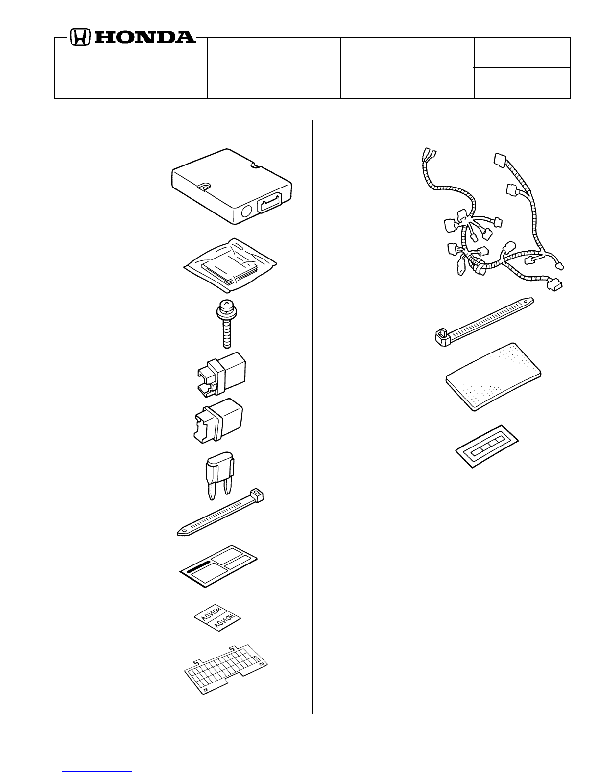
PARTS LIST
Security System (sold separately):
P/N 08E51-S01-101F
Control unit
Owner’s Man ual
(discard)
2 Washer-scre ws
(not used)
Relay 4-pin
Security Harness (sold separately):
P/N 08E55-S01-101
Security harness
5 Wire ties
Cushion tape
Relay 5-pin
2 Fuses (3A)
(not used)
2 Long wire ties
(not used)
Card
(not used)
2 Decals
Fuse box cover
(not used)
Fuse label
© 1999 American Honda Motor Co., Inc - All Rights Reserved. AII 20447 (9908) 1 of 10
Y0540-B
08E55-S01-1010-91
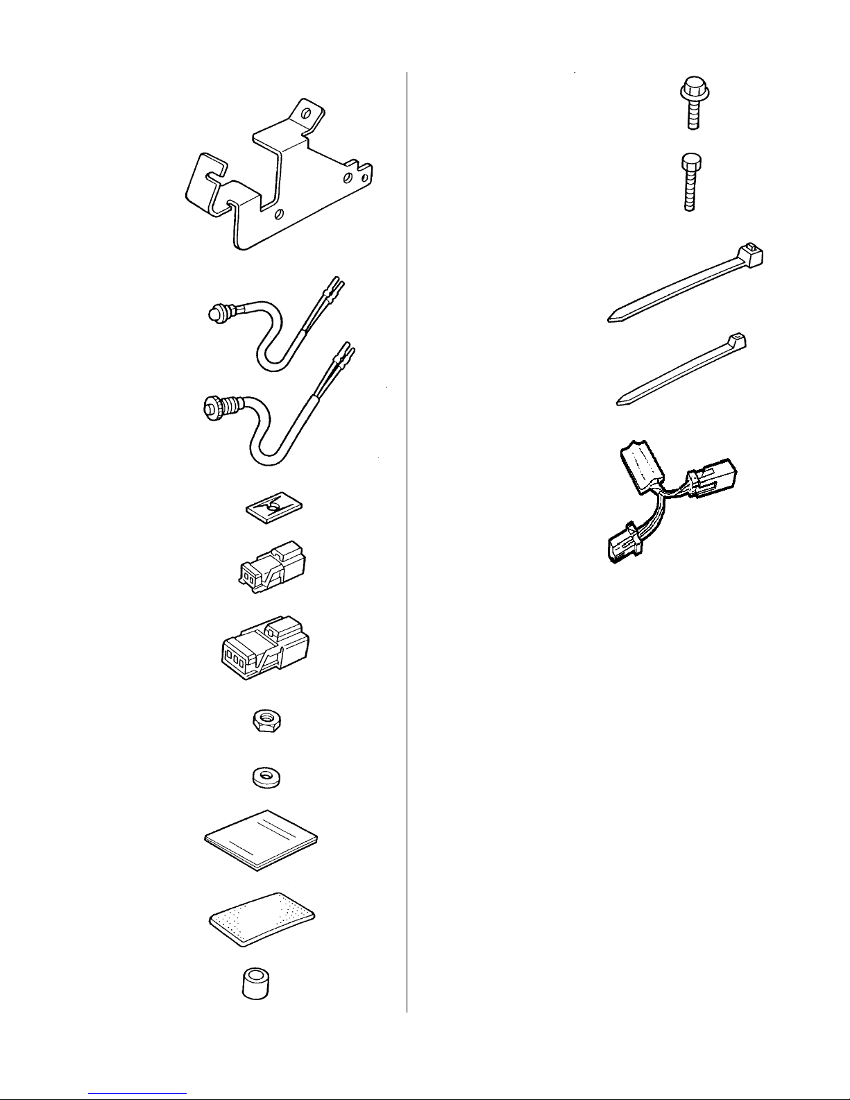
Security Attachment (sold separately):
P/N 08E55-S01-100H
Flange bolt, 6 x 12 mm
Control unit bracket
LED
Disarm switch
Push nut (for LED)
2 Bolts, 4 x 30 mm
Wire tie
4 Short wire ties (white)
Resistor
2-Pin connector
3-Pin connector
Nut
Washer
Owner’s Man ual
Cushion tape
TOOLS AND SUPPLIES REQ UIRED
Phillips screwdriver
Stubby Phillips screwdriver
Drill
5.5 mm and 12 mm Drill bits
T ape measure
10 mm and 12 mm Sockets
Ratchet
7 mm, 10 mm, 12 mm and 17 mm Combination wrenches
Diagonal cutters
Utility knife
Electrical tape
2 Collars
2 of 10 AII 20447 (9908) © 1999 American Honda Motor Co., Inc - All Rights Reserved.
INSTALLATION
Customer Information: The information in this
installation instruction is intended for use only by
skilled technicians who have the proper tools,
equipment, and training to correctly and safely add
equipment to your car . These procedures should
not be attempted by “do-it-y ourselfers .”
NOTE: The Owner’s Man ual included with the Security
Attachment should be placed in the glove box for future
reference. The Owner’s Man ual included with the Security
System should be discarded.
1. Make sure you hav e the anti-theft code f or the radio ,
then write down the frequencies for the preset
buttons.
2. Disconnect the negative cable from the battery.
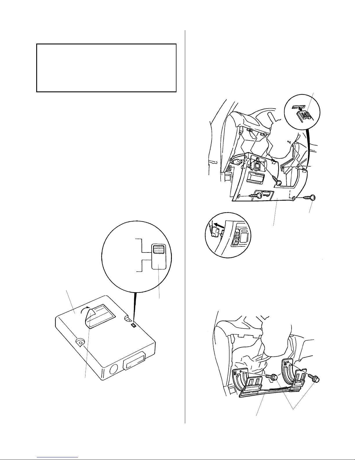
3. Move the switch on the control unit into the correct
mode for the CX and DX models.
4. Remove the driver's dashboard lower cover:
• Remove the three screws.
• Gently pull along the top to release the three
retaining clips.
• Unplug the connector(s) and remove the cov er.
RETAINING
CLIP
CONTROL UNIT
Tear off
this label.
CX/DX
HX/LX/EX
SELF-TAPPING
SCREW
DRIVER'S
DASHBOARD
LOWER COVER
MOONROOF MODEL
5. Remove the knee bolster (two bolts).
The knob is set
in this position
at the factory.
© 1999 American Honda Motor Co., Inc - All Rights Reserved. AII 20447 (9908) 3 of 10
BOLTS
KNEE BOLSTER
 Loading...