

Page 1

honda :: Honda Truck Odyssey LX V6-3.5L (2000)
Page 2

> Relays and Modules > Relays and Modules - Accessories and Optional Equipment > Alarm/Immobilizer Control Unit <--> [Alarm Module, (Vehicle Antitheft)] > Component Information > Locations
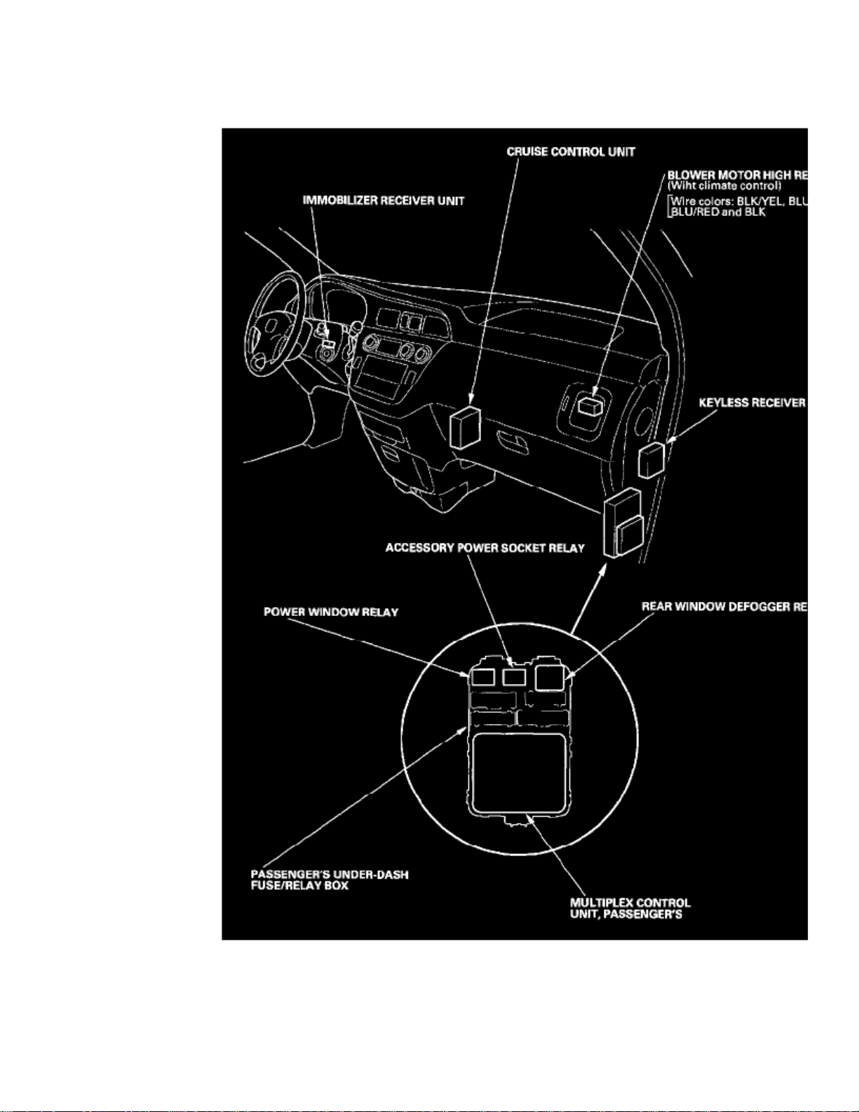
Relay And Control Unit Locations - Dashboard
Page 3

Page 4
> Relays and Modules > Relays and Modules - Accessories and Optional Equipment > Alarm/Immobilizer Control Unit <--> [Alarm Module, (Vehicle Antitheft)] > Component Information > Locations > Page 7
Alarm/Immobilizer Control Unit: Diagrams
Page 5

> Relays and Modules > Relays and Modules - Accessories and Optional Equipment > Alarm/Immobilizer Control Unit <--> [Alarm Module, (Vehicle Antitheft)] >
Component Information > Locations > Page 8
Odyssey LX V6-3.5L (2000)
Page 6
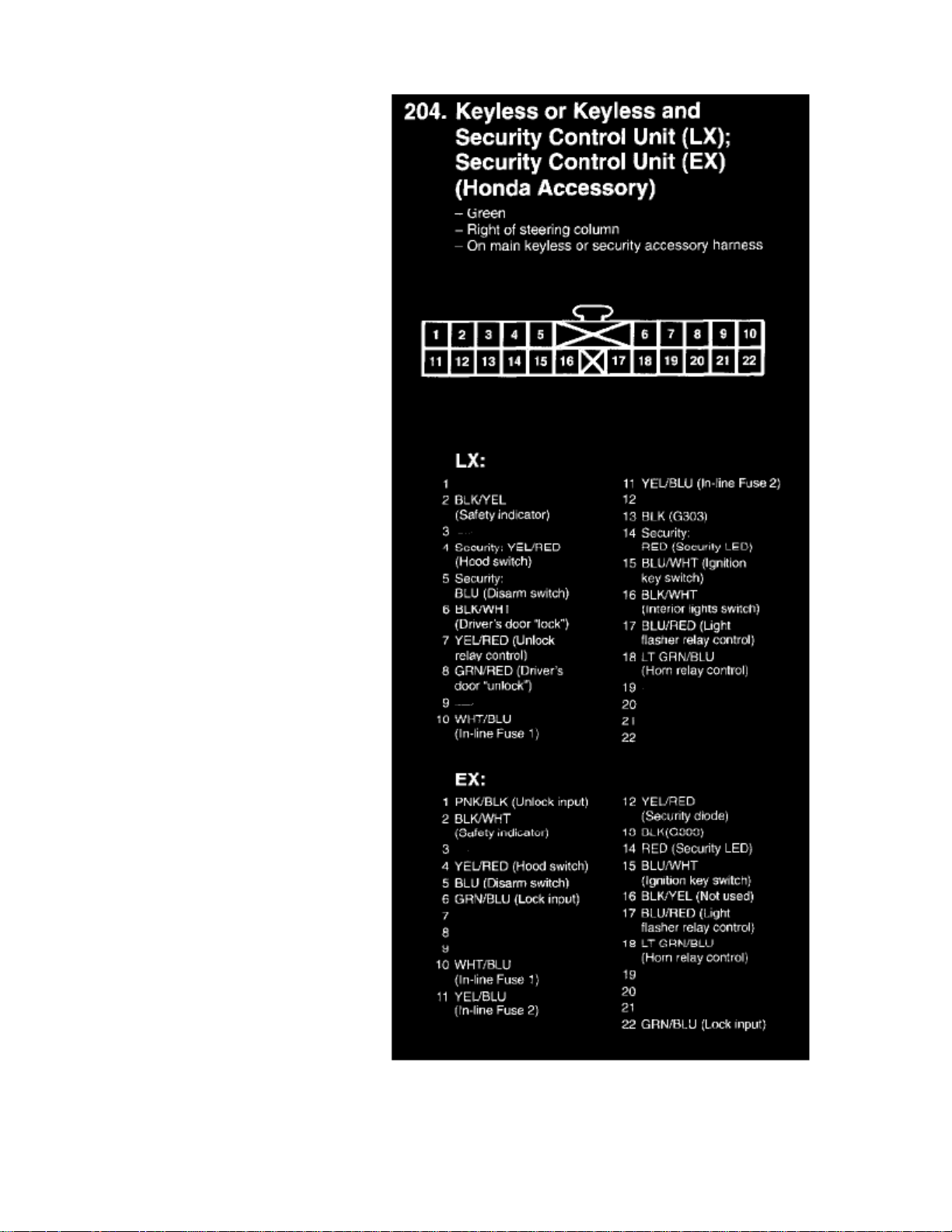
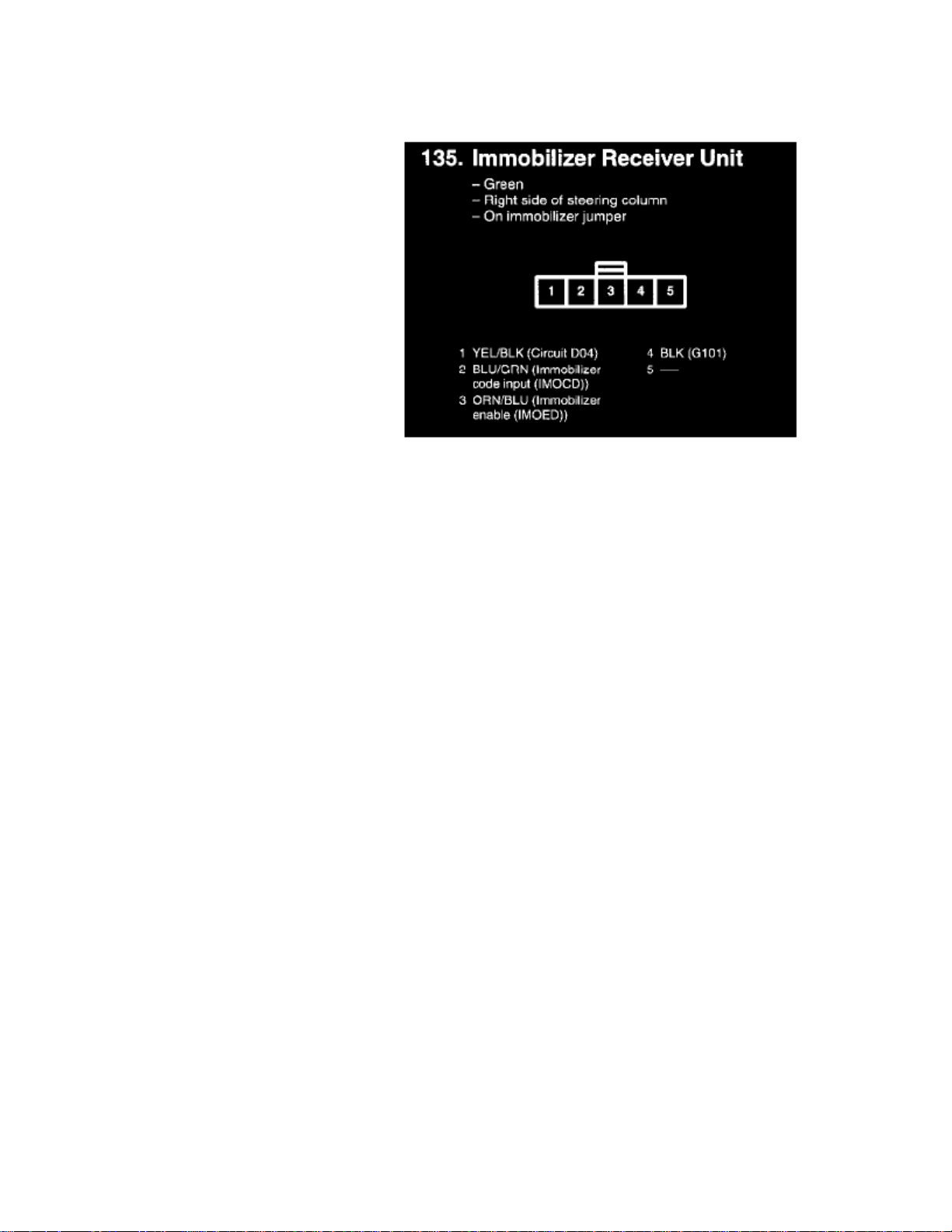
Security Control Unit (LX); Security Control Unit (EX)
Page 7

Page 8

> Relays and Modules > Relays and Modules - Accessories and Optional Equipment > Alarm/Immobilizer Control Unit <--> [Alarm Module, (Vehicle Antitheft)] > Component Information > Locations > Page 9
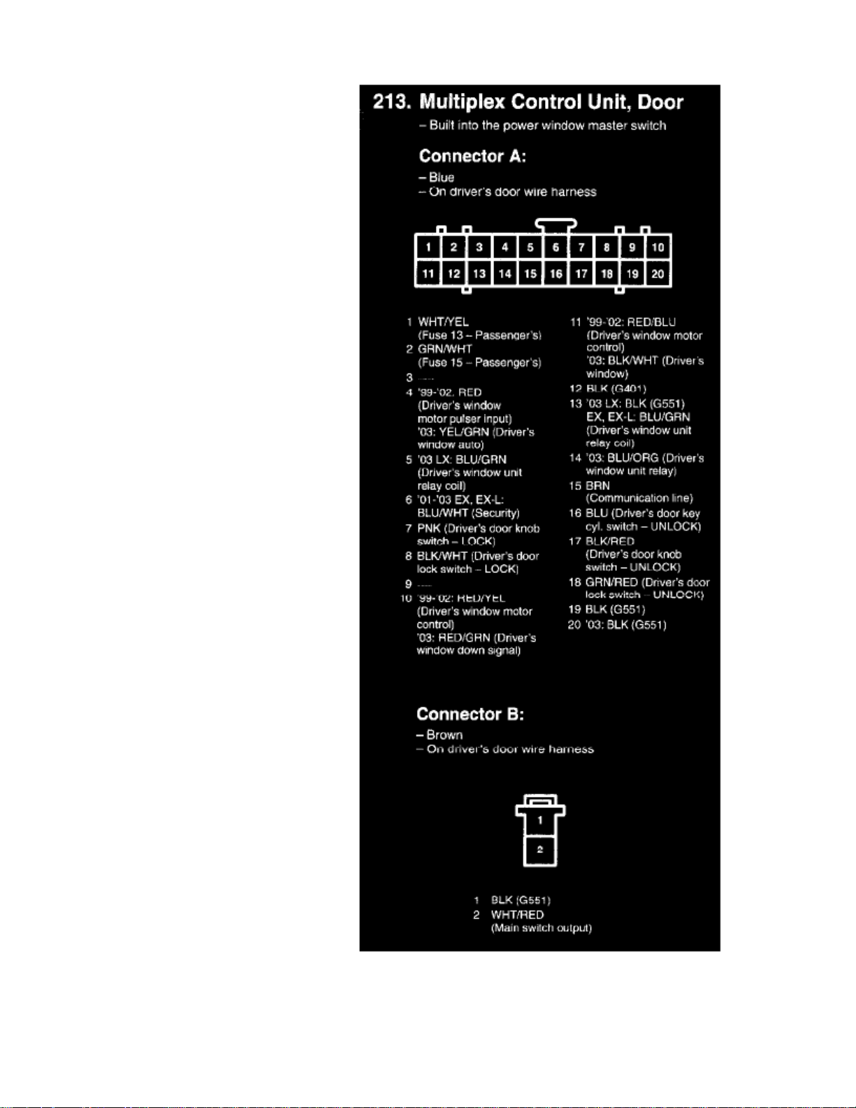
Alarm/Immobilizer Control Unit: Testing and Inspection
Power Door Locks/Factory Keyless/Factory Security
Control Unit Input Test
1. Before testing the keyless entry/power door lock control functions, troubleshoot the multiplex control system.
Driver's multiplex Control Unit:
2. Remove the driver's multiplex control unit from the driver's under-dash fuse/relay box.
3. Inspect the connector and socket terminals to be sure they are all making good contact.
- If the terminals are bent, loose or corroded, repair them as necessary, and recheck the system.
- If the terminals look OK, go to step 4.
Page 9

> Relays and Modules > Relays and Modules - Accessories and Optional Equipment > Alarm/Immobilizer Control Unit <--> [Alarm Module, (Vehicle Antitheft)] >
Component Information > Locations > Page 10
Odyssey LX V6-3.5L (2000)
Page 10

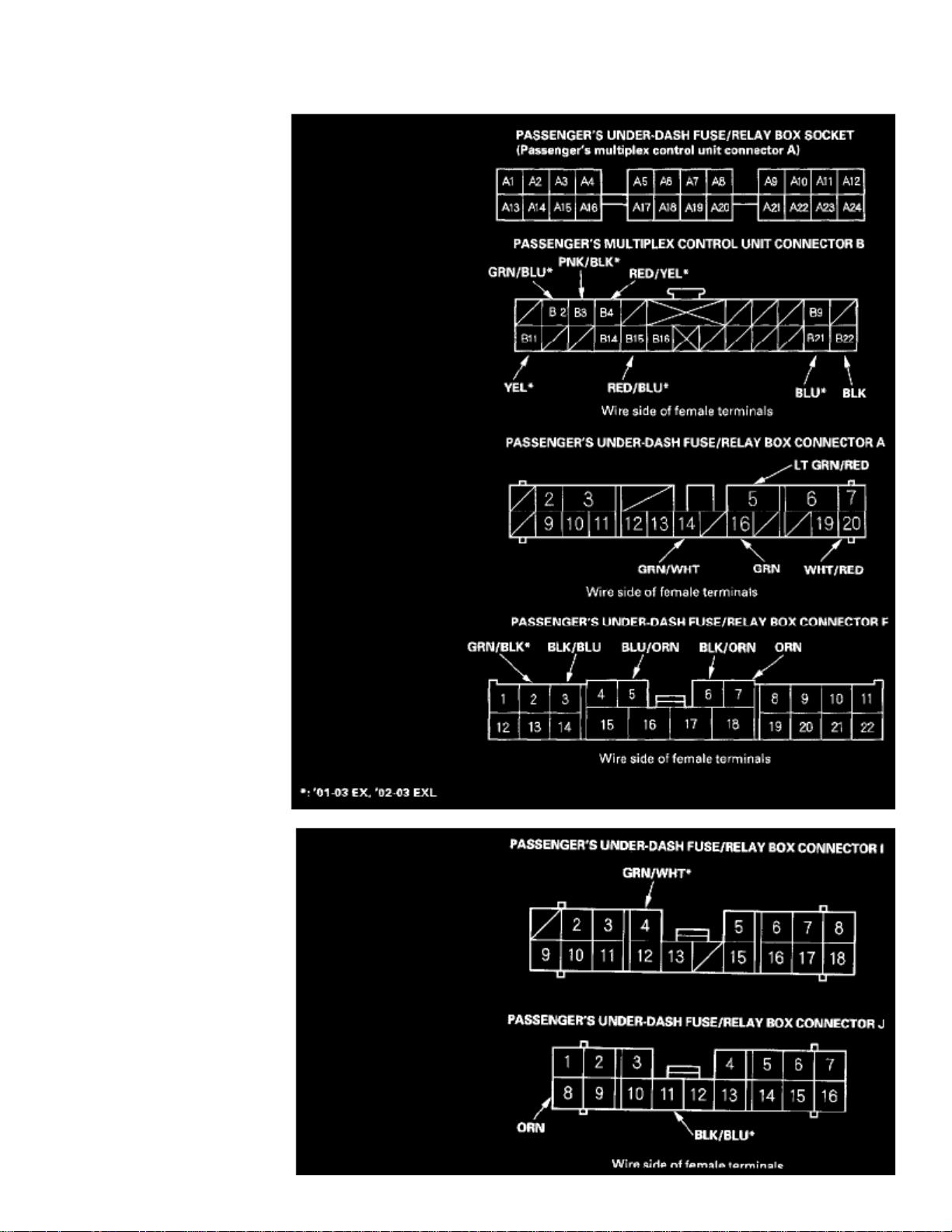
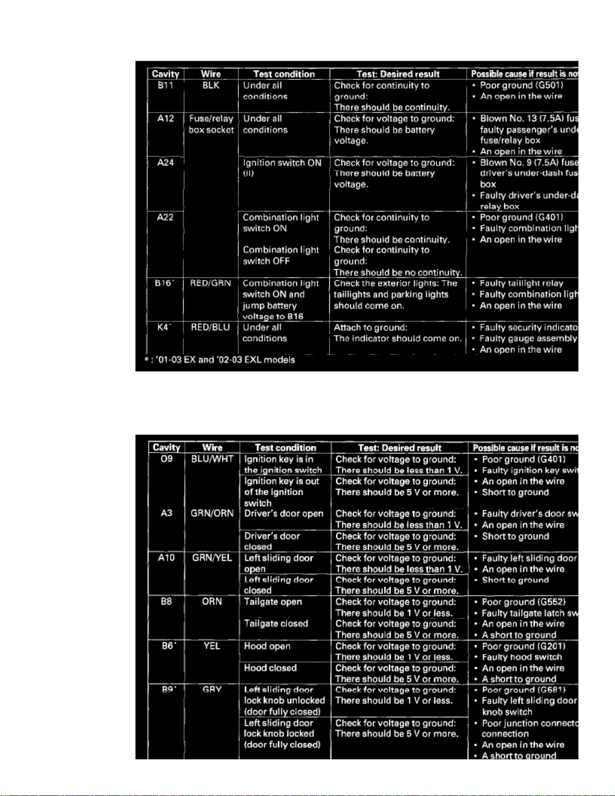
4. With the driver's multiplex control unit still disconnected, make these input tests at the connector and fuse/relay box sockets.
- If any test indicates a problem, find and correct the cause, then recheck the system.
- If all the input tests prove OK, go to step 5.
Page 11

> Relays and Modules > Relays and Modules - Accessories and Optional Equipment > Alarm/Immobilizer Control Unit <--> [Alarm Module, (Vehicle Antitheft)] >
Component Information > Locations > Page 11
Odyssey LX V6-3.5L (2000)
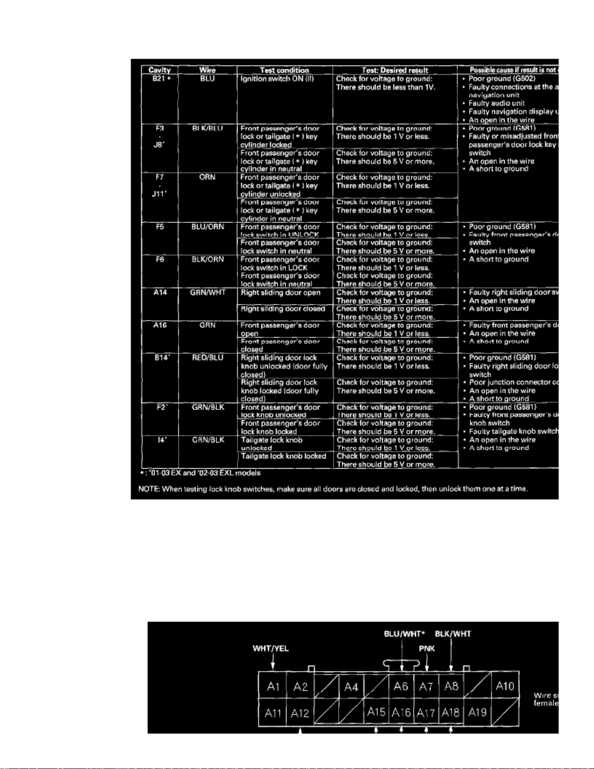
5. Reconnect the driver's multiplex control unit to the fuse/relay box, and perform the following input tests at the appropriate connectors on the back
of the fuse/relay box.-
If any test indicates a problem, find and correct the cause, then recheck the system.
- If all the input tests prove OK, go to step 6.
Passenger's multiplex Control Unit:
6. Remove the passenger's multiplex control unit from the passenger's under-dash fuse/relay box, and disconnect its connector.
Page 12
Page 13

> Relays and Modules > Relays and Modules - Accessories and Optional Equipment > Alarm/Immobilizer Control Unit <--> [Alarm Module, (Vehicle Antitheft)] >
Component Information > Locations > Page 12
Odyssey LX V6-3.5L (2000)
7. Inspect the connector and socket terminals to be sure they are all making good contact.
- If the terminals are bent, loose or corroded, repair them as necessary, and recheck the system.
- If the terminals look OK, go to step 8.
Page 14
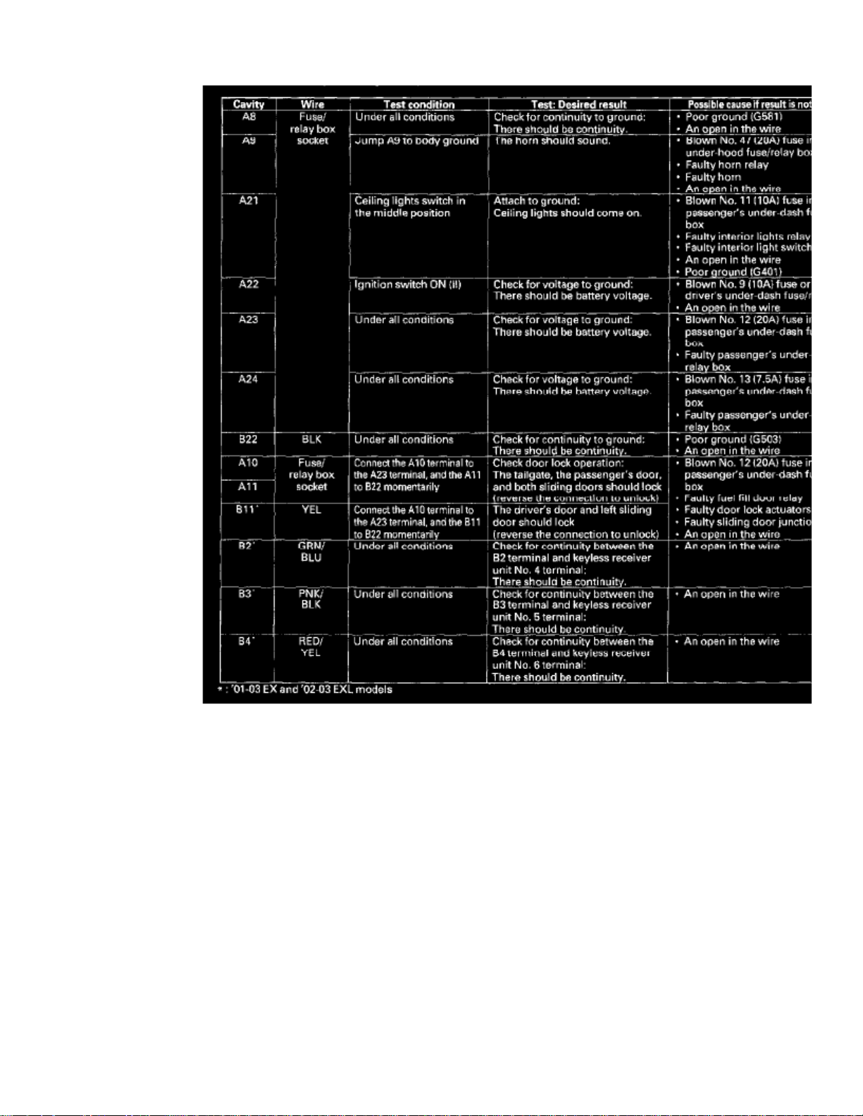
8. With the multiplex control unit still disconnected, make these input tests at the connector and fuse/relay box sockets.
- If any test indicates a problem, find and correct the cause, then recheck the system.
- If all the input tests prove OK, go to step 9.
Page 15

> Relays and Modules > Relays and Modules - Accessories and Optional Equipment > Alarm/Immobilizer Control Unit <--> [Alarm Module, (Vehicle Antitheft)] >
Component Information > Locations > Page 13
Odyssey LX V6-3.5L (2000)
Page 16

9. Reconnect the passenger's multiplex control unit to the fuse/relay box, and perform the following input tests at the appropriate connectors on the
back of the fuse/relay box.-
If any test indicates a problem, find and correct the cause, then recheck the system.
- If all the input tests prove OK, go to step 10.
Door Multiplex Control Unit:
10. Remove the door multiplex control unit, and disconnect its connector.
Page 17

> Relays and Modules > Relays and Modules - Accessories and Optional Equipment > Alarm/Immobilizer Control Unit <--> [Alarm Module, (Vehicle Antitheft)] >
Component Information > Locations > Page 14
Odyssey LX V6-3.5L (2000)
11. Inspect the connector and socket terminals to be sure they are making good contact
- If the terminals are bent, loose or corroded, repair them as necessary, and recheck the system.
- If the terminals look OK, go to step 12.
Page 18

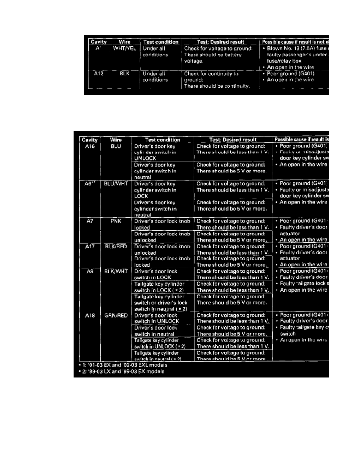
12. With the door unit still disconnected, make these input tests at the connector.
- If any test indicates a problem, find and correct the cause, then recheck the system.
- If all the input tests prove OK, go to step 13.
13. Reconnect the connector to the door unit, and perform the following input tests at the connectors.
- If any test indicates a problem, find and correct the cause, then recheck the system.
- If all the input tests prove OK, go to step 14.
14. If all the input tests prove OK, one of the control units must be faulty. Substitute a known-good control unit for the one that is most likely at fault,
Page 19

then recheck the system. If the system works properly, the original control unit is faulty; replace it. If there is still a malfunction, substitute aknown-good control unit for the next most likely unit to be at fault, and recheck. If the system works properly, the original unit is faulty; replace it.
Page 20

> Relays and Modules > Relays and Modules - Accessories and Optional Equipment > Collision Avoidance Module > Component Information > Locations
Collision Avoidance Module: Locations
212. Behind Left Rear Side Trim Panel (Honda Accy.)
216. Behind Right Rear Side Trim Panel (Honda Accy.)
Page 21

Page 22

> Relays and Modules > Relays and Modules - Accessories and Optional Equipment > Collision Avoidance Module > Component Information > Locations > Page 18
Page 23

Page 24

> Relays and Modules > Relays and Modules - Accessories and Optional Equipment > General Module > Component Information > Diagrams
General Module: Diagrams
Page 25

> Relays and Modules > Relays and Modules - Accessories and Optional Equipment > General Module > Component Information > Diagrams > Page 22
Odyssey LX V6-3.5L (2000)
Page 26
Page 27

> Relays and Modules > Relays and Modules - Accessories and Optional Equipment > General Module > Component Information > Diagrams > Page 23
Odyssey LX V6-3.5L (2000)
Page 28

Page 29

> Relays and Modules > Relays and Modules - Accessories and Optional Equipment > General Module > Component Information > Diagrams > Page 24
Odyssey LX V6-3.5L (2000)
Page 30

Page 31

Page 32

> Relays and Modules > Relays and Modules - Accessories and Optional Equipment > Keyless Entry Module > Component Information > Locations
Keyless Entry Module: Locations
Right Dashboard View
Page 33

> Relays and Modules > Relays and Modules - Accessories and Optional Equipment > Keyless Entry Module > Component Information > Locations > Page 28
Odyssey LX V6-3.5L (2000)
Page 34

Right End Of Dash (Glove Box Removed)
Page 35

Page 36

> Relays and Modules > Relays and Modules - Accessories and Optional Equipment > Keyless Entry Module > Component Information > Locations > Page 29
Keyless Entry Module: Diagrams
Page 37

Page 38

> Relays and Modules > Relays and Modules - Accessories and Optional Equipment > Keyless Entry Module > Component Information > Locations > Page 30
Keyless Entry Module: Testing and Inspection
Power Door Locks/Factory Keyless/Factory Security
Control Unit Input Test
1. Before testing the keyless entry/power door lock control functions, troubleshoot the multiplex control system.
Driver's multiplex Control Unit:
2. Remove the driver's multiplex control unit from the driver's under-dash fuse/relay box.
3. Inspect the connector and socket terminals to be sure they are all making good contact.
- If the terminals are bent, loose or corroded, repair them as necessary, and recheck the system.
- If the terminals look OK, go to step 4.
Page 39

> Relays and Modules > Relays and Modules - Accessories and Optional Equipment > Keyless Entry Module > Component Information > Locations > Page 31
Odyssey LX V6-3.5L (2000)
Page 40
4. With the driver's multiplex control unit still disconnected, make these input tests at the connector and fuse/relay box sockets.
- If any test indicates a problem, find and correct the cause, then recheck the system.
- If all the input tests prove OK, go to step 5.
Page 41

> Relays and Modules > Relays and Modules - Accessories and Optional Equipment > Keyless Entry Module > Component Information > Locations > Page 32
Odyssey LX V6-3.5L (2000)
5. Reconnect the driver's multiplex control unit to the fuse/relay box, and perform the following input tests at the appropriate connectors on the back
of the fuse/relay box.-
If any test indicates a problem, find and correct the cause, then recheck the system.
- If all the input tests prove OK, go to step 6.
Passenger's multiplex Control Unit:
6. Remove the passenger's multiplex control unit from the passenger's under-dash fuse/relay box, and disconnect its connector.
Page 42

Page 43

> Relays and Modules > Relays and Modules - Accessories and Optional Equipment > Keyless Entry Module > Component Information > Locations > Page 33
Odyssey LX V6-3.5L (2000)
7. Inspect the connector and socket terminals to be sure they are all making good contact.
- If the terminals are bent, loose or corroded, repair them as necessary, and recheck the system.
- If the terminals look OK, go to step 8.
Page 44

8. With the multiplex control unit still disconnected, make these input tests at the connector and fuse/relay box sockets.
- If any test indicates a problem, find and correct the cause, then recheck the system.
- If all the input tests prove OK, go to step 9.
Page 45

> Relays and Modules > Relays and Modules - Accessories and Optional Equipment > Keyless Entry Module > Component Information > Locations > Page 34
Odyssey LX V6-3.5L (2000)
Page 46
9. Reconnect the passenger's multiplex control unit to the fuse/relay box, and perform the following input tests at the appropriate connectors on the
back of the fuse/relay box.-
If any test indicates a problem, find and correct the cause, then recheck the system.
- If all the input tests prove OK, go to step 10.
Door Multiplex Control Unit:
10. Remove the door multiplex control unit, and disconnect its connector.
Page 47

> Relays and Modules > Relays and Modules - Accessories and Optional Equipment > Keyless Entry Module > Component Information > Locations > Page 35
Odyssey LX V6-3.5L (2000)
11. Inspect the connector and socket terminals to be sure they are making good contact
- If the terminals are bent, loose or corroded, repair them as necessary, and recheck the system.
- If the terminals look OK, go to step 12.
Page 48
12. With the door unit still disconnected, make these input tests at the connector.
- If any test indicates a problem, find and correct the cause, then recheck the system.
- If all the input tests prove OK, go to step 13.
13. Reconnect the connector to the door unit, and perform the following input tests at the connectors.
- If any test indicates a problem, find and correct the cause, then recheck the system.
- If all the input tests prove OK, go to step 14.
14. If all the input tests prove OK, one of the control units must be faulty. Substitute a known-good control unit for the one that is most likely at fault,
Page 49

then recheck the system. If the system works properly, the original control unit is faulty; replace it. If there is still a malfunction, substitute aknown-good control unit for the next most likely unit to be at fault, and recheck. If the system works properly, the original unit is faulty; replace it.
Page 50

> Relays and Modules > Relays and Modules - Accessories and Optional Equipment > Navigation Module > Component Information > Technical Service Bulletins > Customer Interest for Navigation Module: > 04-018 > Sep >
10 > Navigation System - 2.11C Patch for Various Issues
Navigation Module: Customer InterestNavigation System - 2.11C Patch for Various Issues
04-018
September 10, 2010
Applies To: 2000-03 Odyssey With Navigation System - ALL
2004 Odyssey With Navigation System - From VIN 5FNRL1...4B000001 thru VIN 5FNRL1...4B070665
2003 Pilot With Navigation System - ALL
2004 Pilot With Navigation System - From VIN 2HKYF1...4H500001 thru VIN 2HKYF1...4H556658
Navigation System 2.11C Patch CD: Fixes Problems With Personal Address or Previous Destinations Listings With 2.11A or 2.11B DVD
(Supersedes 04-018, dated March 19, 2004, to revise the information marked by asterisks)
*REVISION SUMMARY
^ Under PARTS INFORMATION, the phone number for ordering navigation DVDS and patch CD replacement information was changed.
^ REPAIR PROCEDURE B was added. Use this procedure only if you no longer have the 2.11C patch CD.*
SYMPTOM
On 2004 Odyssey and Pilots, and on 2000-03 Odysseys and 2003 Pilots upgraded to 2.11B, none of the personal addresses can be seen when you viewthe Personal Address" list using the touch screen Page Up/Page Down" buttons. The personal addresses can be seen, however, when using the ZoomIn/Zoom Out" buttons or the joystick.
In addition, on 2000-03 Odyssey and 2003 Pilot, these symptoms may appear:
^
The Previous Destinations" button may become inactive, making it impossible to see any old or newly added Previous Destinations. This happens ifthe system had less than 20 Previous Destinations when it was upgraded to 2.11 B.
^ Some of the destinations stored in the Previous Destination" and Personal Address" lists may appear on the incorrect side of the road.
PROBABLE CAUSE
A problem in the navigation software.
CORRECTIVE ACTION
Download the corrective 2.11C patch CD into the navigation system.
: NOTE
This patch CD does not work with DVDs stamped 2.05B or earlier. If the 2.11C software is loaded, the system displays DVD Disc reading error(Incorrect DVD Disc) when the original DVD is reinserted. The only way to fix this disc reading error is to enter the Diagnostic Mode and do aForced Download using the customer's original DVD.
*PARTS INFORMATION
Page 51

> Relays and Modules > Relays and Modules - Accessories and Optional Equipment > Navigation Module > Component Information > Technical Service Bulletins >
Customer Interest for Navigation Module: > 04-018 > Sep > 10 > Navigation System - 2.11C Patch for Various Issues > Page 44
Odyssey LX V6-3.5L (2000)
Each dealer was automatically sent one 2.11C patch CD.
Additional patch CDs are no longer available. If you no longer have one, call Navteq at 888-291-4675, press 2 for Honda dealers, then press 2 for mappatch, and ask for navigation DVD 2.11C. This navigation DVD replaces the customer's original navigation DVD. Refer to REPAIR PROCEDURE B.
: NOTE
The 2.11 C navigation DVD includes the 2.11C CD patch.*
TOOL INFORMATION
SCS Service Connector:
T/N 07PAZ-0010100
Page 52

WARRANTY CLAIM INFORMATION
The normal warranty applies.
Operation Number: 053011
Flat Rate Time: 0.3 hour
Failed Part: P/N 39010-50K-A12
Defect Code: 03214
Symptom Code: 03278
Skill Level: Repair Technician
REPAIR PROCEDURE A
:NOTE
Use this procedure if you have the navigation patch CD. If you no longer have the patch CD, contact Navteq to get a navigation DVD (version2.11C) and go to REPAIR PROCEDURE B.
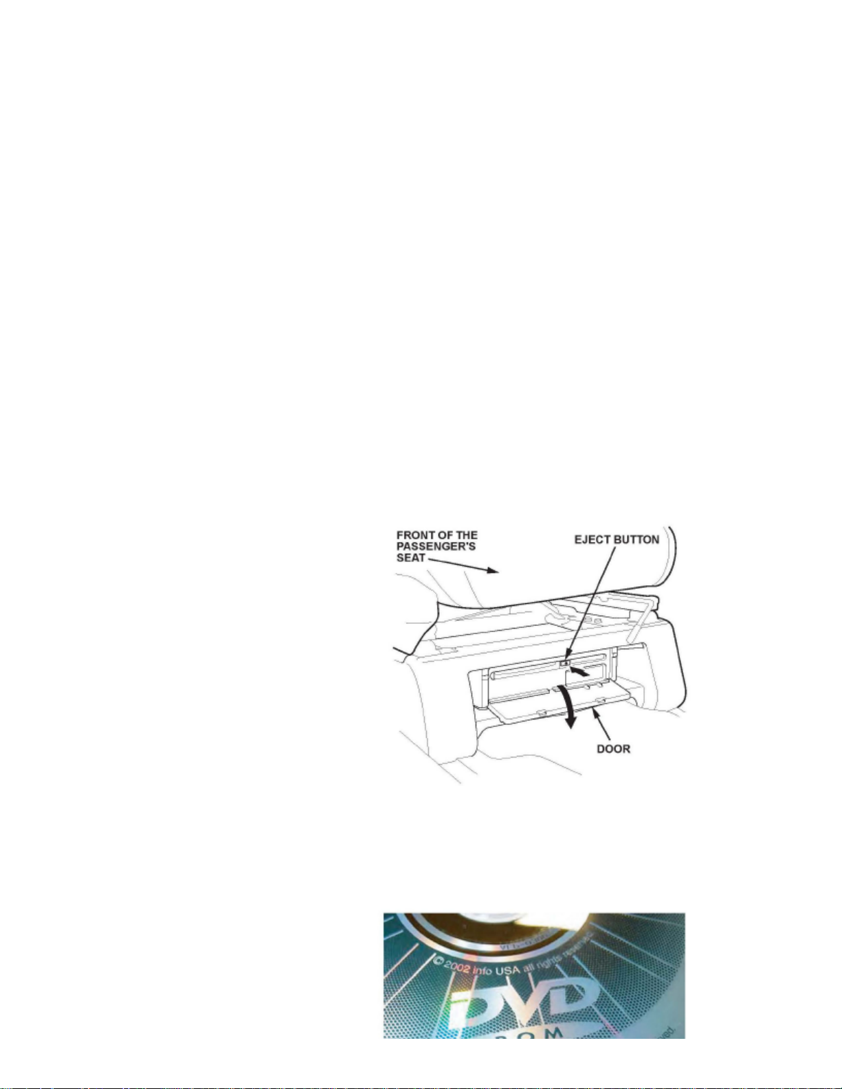
1. Locate the navigation unit under the front passenger's seat.
2. Slide the front passenger's seat rearward.
3. Start the engine.
4. Open the door of the navigation unit.
Page 53

> Relays and Modules > Relays and Modules - Accessories and Optional Equipment > Navigation Module > Component Information > Technical Service Bulletins >
Customer Interest for Navigation Module: > 04-018 > Sep > 10 > Navigation System - 2.11C Patch for Various Issues > Page 45
Odyssey LX V6-3.5L (2000)
5. Press the EJECT button, and remove the navigation DVD. Confirm that it says 2.11A or 2.11B.
^
If it is 2.05B or earlier, do not load the 2.11C patch CD. This patch CD does not work with DVDs stamped 2.05B or earlier. Return the vehicle tothe customer, and go over the Personal Address and Previous Destinations features.
Page 54

^ If it is 2.11A or 2.11B, go to step 6.
6. Insert the patch CD with the writing side up, then close the door.
7. Check that the navigation screen goes black for several seconds.
^ If a "DVD Read Error" message appears, go to step 8.
^ If the screen displays an Updating Software load progress bar, the system is operating properly. Go to step 16.
8. Turn the ignition switch to LOCK (0).
9. Slide the passenger's seat forward.
10. Attach the SCS service connector to the navigation service check connector (located behind the navigation unit).
11. Start the engine.
12. Detach the SCS service connector.
13. Verify that the Diagnosis menu for the picture diagnosis starts up and then changes to the System Links menu. Press the Return touch screen button
to access the Diagnostic menu.
14. From the Diagnostic menu, press the Unit Check touch screen button.
15. From the Unit Check menu, press the Force Download touch screen button.
:NOTE
Do not press any other Diagnostic menu touch screen buttons; doing so could result in the loss of the customer's personal data.
16. When you see a DVD Disc reading error (Incorrect DVD Disc) message displayed on the screen (which is normal), remove the patch CD from the
navigation unit, then reinsert the customer's 2.11A or 2.11B DVD.
17. Turn the ignition switch to LOCK (0), wait 30 seconds, then restart the engine.
18. Verify that the navigation system works properly by test-driving the vehicle on a mapped road until the road name appears at the bottom of the
screen.
:NOTE
Do not enter a route until this step is complete.
19. Return the patch CD and installation instructions to the jewel case, and retain it for updating the next vehicle.
REPAIR PROCEDURE B
:NOTE
Use this procedure only if you no longer have the navigation patch CD and received a navigation DVD (version 2.11C) from Navteq.
1. Locate the navigation unit under the front passenger's seat.
2. Slide the front passenger's seat rearward.
Page 55

> Relays and Modules > Relays and Modules - Accessories and Optional Equipment > Navigation Module > Component Information > Technical Service Bulletins >
Customer Interest for Navigation Module: > 04-018 > Sep > 10 > Navigation System - 2.11C Patch for Various Issues > Page 46
Odyssey LX V6-3.5L (2000)
3. Start the engine.
4. Open the door of the navigation unit.
5. Press the EJECT button, and remove the original navigation DVD. Confirm that it says 2.11A or 2.11B.
^
If it is 2.05B or earlier, do not load the navigation DVD (version 2.11C). This navigation DVD does not work with DVDs stamped 2.05B orearlier. Return the vehicle to the customer, and go over the Personal Address and Previous Destinations features.
^ If it is 2.11A or 2.11B, go to step 6.
6. Insert the replacement navigation DVD with the writing side up, then close the door.
Page 56

7. Follow the instructions on the label that came with the navigation DVD.
8. Verify that the navigation system works properly by test-driving the vehicle on a mapped road until the road name appears at the bottom of the
screen.
:NOTE
Do not enter a route until this step is complete.
9. Mail the customer's original DVD to:
Alpine Electronics 19145 Gramercy Place Torrance CA 90501
Disclaimer
Page 57

Page 58

> Relays and Modules > Relays and Modules - Accessories and Optional Equipment > Navigation Module > Component Information > Technical Service Bulletins > Customer Interest for Navigation Module: > 03-074 > Oct >
03 > Navigation System - Reboots/Incorrect Displays
Navigation Module: Customer InterestNavigation System - Reboots/Incorrect Displays
03-074
October 7, 2003
Applies To: 2000-03 Odyssey With Navigation System - ALL2003 Pilot With Navigation System - ALL
Navigation System Reboots While Using "Advanced" Category or Displays U.S. Post Office Phone Numbers Incorrectly
SYMPTOM
The navigation system reboots to the globe screen when looking for a business (PO1) in the "Advanced" category (Pilot only), or when selecting places,the navigation system displays most U.S. post office phone numbers as 000-1111 after the area code (Pilot and Odyssey).
PROBABLE CAUSE
There is a problem in the navigation software.
CORRECTIVE ACTION
Download the corrective patch CD into the navigation system.
NOTE:
^ This patch CD works only with DVDs stamped 2.05b or earlier.
^
This patch CD also fixes a problem with DVDs marked 2.05a on Pilot. Occasionally while driving the vehicle, the navigation map displaymomentarily reverses from a white background with black roads to black background with white roads.
^ After the patch CD installation, the phone numbers for most post offices are no longer shown.
^
This patch CD does not update the database or map coverage area. For the newest city coverage information and navigation DVD-ROMs, refer tothe Honda web site.
PARTS INFORMATION
TOOL INFORMATION
SCS Service Connector:
P/N 07PAZ-0010100, H/C 4231189
WARRANTY CLAIM INFORMATION
In warranty: The normal warranty applies.
Operation Number: 053011
Page 59

> Relays and Modules > Relays and Modules - Accessories and Optional Equipment > Navigation Module > Component Information > Technical Service Bulletins >
Customer Interest for Navigation Module: > 03-074 > Oct > 03 > Navigation System - Reboots/Incorrect Displays > Page 51
Odyssey LX V6-3.5L (2000)
Each dealer will be automatically sent one patch CD. If you lose the patch CD, please call Navigation DVD Orders, and ask for Navigation Patch DiscCD-ROM 2.05c.
Flat Rate Time: 0.3 hour
Failed Part:
39540-S0X-A11 H/C 6281901
Defect Code: 039
Contention Code: B99
Template ID: 03-074A
Skill Level: Repair Technician
Page 60

Out of warranty: Any repair performed after warranty expiration may be eligible for goodwill consideration by the District Parts and Service Manager or your ZoneOffice. You must request consideration, and get a decision, before starting work.
REPAIR PROCEDURE
1. Slide the front passenger's seat to the rear.
2. Turn the ignition switch to ON (II).
3. Open the door of the navigation unit.
4. Press the EJECT button, and remove the customer's DVD-ROM. Check if it is 2.05b or earlier.
^ If it is 205c, the update is not needed
^ If it is 2.05b or earlier, go to step 5.
Page 61

> Relays and Modules > Relays and Modules - Accessories and Optional Equipment > Navigation Module > Component Information > Technical Service Bulletins >
Customer Interest for Navigation Module: > 03-074 > Oct > 03 > Navigation System - Reboots/Incorrect Displays > Page 52
Odyssey LX V6-3.5L (2000)
5. Insert the patch CD with the writing side up. Close the door.
6. Check that the navigation screen goes black for several seconds.
^ If a "DVD Read Error" message appears, go to step 7.
^
If the screen displays an "Updating Software" load progress bar, the system is operating properly. When you see a "Database Error" message,go to step 14.
7. Turn off the ignition switch, and slide the passenger's seat forward.
8. Attach the SCS service connector to the navigation service check connector (located behind the navigation unit).
Page 62

9. Turn the ignition switch to ON (II).
10.
Verify that the "Diagnosis" menu for the picture diagnosis starts up and then changes to the "System Links" menu. Press the "Return" touch screenbutton to access the "Diagnostic" menu.
11. From the "Diagnostic" menu, press the "Unit Check" touch screen button.
12. From the "Unit Check" menu, press the "Force Download" touch screen button.
NOTE:
Do not touch any other "Diagnostic" menu touch screen buttons; doing so could result in the loss of the customer's personal data.
13. When you see a "Database Error" message displayed on the navigation screen, remove the SCS service connector.
14. Remove the patch CD from the navigation unit. then, reinsert the customer's DVD-ROM.
15. Verify that the navigation system works properly by test-driving the vehicle to a programmed driving destination you select.
16. Return the patch disc and installation instructions to the jewel case, and retain it for the next use.
Disclaimer
Page 63

Page 64

> Relays and Modules > Relays and Modules - Accessories and Optional Equipment > Navigation Module > Component Information > Technical Service Bulletins > All Technical Service Bulletins for Navigation Module: > 04-
018 > Sep > 10 > Navigation System - 2.11C Patch for Various Issues
Navigation Module: All Technical Service BulletinsNavigation System - 2.11C Patch for Various Issues
04-018
September 10, 2010
Applies To: 2000-03 Odyssey With Navigation System - ALL
2004 Odyssey With Navigation System - From VIN 5FNRL1...4B000001 thru VIN 5FNRL1...4B070665
2003 Pilot With Navigation System - ALL
2004 Pilot With Navigation System - From VIN 2HKYF1...4H500001 thru VIN 2HKYF1...4H556658
Navigation System 2.11C Patch CD: Fixes Problems With Personal Address or Previous Destinations Listings With 2.11A or 2.11B DVD
(Supersedes 04-018, dated March 19, 2004, to revise the information marked by asterisks)
*REVISION SUMMARY
^ Under PARTS INFORMATION, the phone number for ordering navigation DVDS and patch CD replacement information was changed.
^ REPAIR PROCEDURE B was added. Use this procedure only if you no longer have the 2.11C patch CD.*
SYMPTOM
On 2004 Odyssey and Pilots, and on 2000-03 Odysseys and 2003 Pilots upgraded to 2.11B, none of the personal addresses can be seen when you viewthe Personal Address" list using the touch screen Page Up/Page Down" buttons. The personal addresses can be seen, however, when using the ZoomIn/Zoom Out" buttons or the joystick.
In addition, on 2000-03 Odyssey and 2003 Pilot, these symptoms may appear:
^
The Previous Destinations" button may become inactive, making it impossible to see any old or newly added Previous Destinations. This happens ifthe system had less than 20 Previous Destinations when it was upgraded to 2.11 B.
^ Some of the destinations stored in the Previous Destination" and Personal Address" lists may appear on the incorrect side of the road.
PROBABLE CAUSE
A problem in the navigation software.
CORRECTIVE ACTION
Download the corrective 2.11C patch CD into the navigation system.
: NOTE
This patch CD does not work with DVDs stamped 2.05B or earlier. If the 2.11C software is loaded, the system displays DVD Disc reading error(Incorrect DVD Disc) when the original DVD is reinserted. The only way to fix this disc reading error is to enter the Diagnostic Mode and do aForced Download using the customer's original DVD.
*PARTS INFORMATION
Page 65

> Relays and Modules > Relays and Modules - Accessories and Optional Equipment > Navigation Module > Component Information > Technical Service Bulletins > All
Technical Service Bulletins for Navigation Module: > 04-018 > Sep > 10 > Navigation System - 2.11C Patch for Various Issues > Page 58
Odyssey LX V6-3.5L (2000)
Each dealer was automatically sent one 2.11C patch CD.
Additional patch CDs are no longer available. If you no longer have one, call Navteq at 888-291-4675, press 2 for Honda dealers, then press 2 for mappatch, and ask for navigation DVD 2.11C. This navigation DVD replaces the customer's original navigation DVD. Refer to REPAIR PROCEDURE B.
: NOTE
The 2.11 C navigation DVD includes the 2.11C CD patch.*
TOOL INFORMATION
SCS Service Connector:
T/N 07PAZ-0010100
Page 66
WARRANTY CLAIM INFORMATION
The normal warranty applies.
Operation Number: 053011
Flat Rate Time: 0.3 hour
Failed Part: P/N 39010-50K-A12
Defect Code: 03214
Symptom Code: 03278
Skill Level: Repair Technician
REPAIR PROCEDURE A
:NOTE
Use this procedure if you have the navigation patch CD. If you no longer have the patch CD, contact Navteq to get a navigation DVD (version2.11C) and go to REPAIR PROCEDURE B.
1. Locate the navigation unit under the front passenger's seat.
2. Slide the front passenger's seat rearward.
3. Start the engine.
4. Open the door of the navigation unit.
Page 67

> Relays and Modules > Relays and Modules - Accessories and Optional Equipment > Navigation Module > Component Information > Technical Service Bulletins > All
Technical Service Bulletins for Navigation Module: > 04-018 > Sep > 10 > Navigation System - 2.11C Patch for Various Issues > Page 59
Odyssey LX V6-3.5L (2000)
5. Press the EJECT button, and remove the navigation DVD. Confirm that it says 2.11A or 2.11B.
^
If it is 2.05B or earlier, do not load the 2.11C patch CD. This patch CD does not work with DVDs stamped 2.05B or earlier. Return the vehicle tothe customer, and go over the Personal Address and Previous Destinations features.
Page 68

^ If it is 2.11A or 2.11B, go to step 6.
6. Insert the patch CD with the writing side up, then close the door.
7. Check that the navigation screen goes black for several seconds.
^ If a "DVD Read Error" message appears, go to step 8.
^ If the screen displays an Updating Software load progress bar, the system is operating properly. Go to step 16.
8. Turn the ignition switch to LOCK (0).
9. Slide the passenger's seat forward.
10. Attach the SCS service connector to the navigation service check connector (located behind the navigation unit).
11. Start the engine.
12. Detach the SCS service connector.
13. Verify that the Diagnosis menu for the picture diagnosis starts up and then changes to the System Links menu. Press the Return touch screen button
to access the Diagnostic menu.
14. From the Diagnostic menu, press the Unit Check touch screen button.
15. From the Unit Check menu, press the Force Download touch screen button.
:NOTE
Do not press any other Diagnostic menu touch screen buttons; doing so could result in the loss of the customer's personal data.
16. When you see a DVD Disc reading error (Incorrect DVD Disc) message displayed on the screen (which is normal), remove the patch CD from the
navigation unit, then reinsert the customer's 2.11A or 2.11B DVD.
17. Turn the ignition switch to LOCK (0), wait 30 seconds, then restart the engine.
18. Verify that the navigation system works properly by test-driving the vehicle on a mapped road until the road name appears at the bottom of the
screen.
:NOTE
Do not enter a route until this step is complete.
19. Return the patch CD and installation instructions to the jewel case, and retain it for updating the next vehicle.
REPAIR PROCEDURE B
:NOTE
Use this procedure only if you no longer have the navigation patch CD and received a navigation DVD (version 2.11C) from Navteq.
1. Locate the navigation unit under the front passenger's seat.
2. Slide the front passenger's seat rearward.
Page 69

> Relays and Modules > Relays and Modules - Accessories and Optional Equipment > Navigation Module > Component Information > Technical Service Bulletins > All
Technical Service Bulletins for Navigation Module: > 04-018 > Sep > 10 > Navigation System - 2.11C Patch for Various Issues > Page 60
Odyssey LX V6-3.5L (2000)
3. Start the engine.
4. Open the door of the navigation unit.
5. Press the EJECT button, and remove the original navigation DVD. Confirm that it says 2.11A or 2.11B.
^
If it is 2.05B or earlier, do not load the navigation DVD (version 2.11C). This navigation DVD does not work with DVDs stamped 2.05B orearlier. Return the vehicle to the customer, and go over the Personal Address and Previous Destinations features.
^ If it is 2.11A or 2.11B, go to step 6.
6. Insert the replacement navigation DVD with the writing side up, then close the door.
Page 70

7. Follow the instructions on the label that came with the navigation DVD.
8. Verify that the navigation system works properly by test-driving the vehicle on a mapped road until the road name appears at the bottom of the
screen.
:NOTE
Do not enter a route until this step is complete.
9. Mail the customer's original DVD to:
Alpine Electronics 19145 Gramercy Place Torrance CA 90501
Disclaimer
Page 71

Page 72

> Relays and Modules > Relays and Modules - Accessories and Optional Equipment > Navigation Module > Component Information > Technical Service Bulletins > All Technical Service Bulletins for Navigation Module: > 03-
074 > Oct > 03 > Navigation System - Reboots/Incorrect Displays
Navigation Module: All Technical Service BulletinsNavigation System - Reboots/Incorrect Displays
03-074
October 7, 2003
Applies To: 2000-03 Odyssey With Navigation System - ALL2003 Pilot With Navigation System - ALL
Navigation System Reboots While Using "Advanced" Category or Displays U.S. Post Office Phone Numbers Incorrectly
SYMPTOM
The navigation system reboots to the globe screen when looking for a business (PO1) in the "Advanced" category (Pilot only), or when selecting places,the navigation system displays most U.S. post office phone numbers as 000-1111 after the area code (Pilot and Odyssey).
PROBABLE CAUSE
There is a problem in the navigation software.
CORRECTIVE ACTION
Download the corrective patch CD into the navigation system.
NOTE:
^ This patch CD works only with DVDs stamped 2.05b or earlier.
^
This patch CD also fixes a problem with DVDs marked 2.05a on Pilot. Occasionally while driving the vehicle, the navigation map displaymomentarily reverses from a white background with black roads to black background with white roads.
^ After the patch CD installation, the phone numbers for most post offices are no longer shown.
^
This patch CD does not update the database or map coverage area. For the newest city coverage information and navigation DVD-ROMs, refer tothe Honda web site.
PARTS INFORMATION
TOOL INFORMATION
SCS Service Connector:
P/N 07PAZ-0010100, H/C 4231189
WARRANTY CLAIM INFORMATION
In warranty: The normal warranty applies.
Operation Number: 053011
Page 73

> Relays and Modules > Relays and Modules - Accessories and Optional Equipment > Navigation Module > Component Information > Technical Service Bulletins > All
Technical Service Bulletins for Navigation Module: > 03-074 > Oct > 03 > Navigation System - Reboots/Incorrect Displays > Page 65
Odyssey LX V6-3.5L (2000)
Each dealer will be automatically sent one patch CD. If you lose the patch CD, please call Navigation DVD Orders, and ask for Navigation Patch DiscCD-ROM 2.05c.
Flat Rate Time: 0.3 hour
Failed Part:
39540-S0X-A11 H/C 6281901
Defect Code: 039
Contention Code: B99
Template ID: 03-074A
Skill Level: Repair Technician
Page 74

Out of warranty: Any repair performed after warranty expiration may be eligible for goodwill consideration by the District Parts and Service Manager or your ZoneOffice. You must request consideration, and get a decision, before starting work.
REPAIR PROCEDURE
1. Slide the front passenger's seat to the rear.
2. Turn the ignition switch to ON (II).
3. Open the door of the navigation unit.
4. Press the EJECT button, and remove the customer's DVD-ROM. Check if it is 2.05b or earlier.
^ If it is 205c, the update is not needed
^ If it is 2.05b or earlier, go to step 5.
Page 75

> Relays and Modules > Relays and Modules - Accessories and Optional Equipment > Navigation Module > Component Information > Technical Service Bulletins > All
Technical Service Bulletins for Navigation Module: > 03-074 > Oct > 03 > Navigation System - Reboots/Incorrect Displays > Page 66
Odyssey LX V6-3.5L (2000)
5. Insert the patch CD with the writing side up. Close the door.
6. Check that the navigation screen goes black for several seconds.
^ If a "DVD Read Error" message appears, go to step 7.
^
If the screen displays an "Updating Software" load progress bar, the system is operating properly. When you see a "Database Error" message,go to step 14.
7. Turn off the ignition switch, and slide the passenger's seat forward.
8. Attach the SCS service connector to the navigation service check connector (located behind the navigation unit).
Page 76

9. Turn the ignition switch to ON (II).
10.
Verify that the "Diagnosis" menu for the picture diagnosis starts up and then changes to the "System Links" menu. Press the "Return" touch screenbutton to access the "Diagnostic" menu.
11. From the "Diagnostic" menu, press the "Unit Check" touch screen button.
12. From the "Unit Check" menu, press the "Force Download" touch screen button.
NOTE:
Do not touch any other "Diagnostic" menu touch screen buttons; doing so could result in the loss of the customer's personal data.
13. When you see a "Database Error" message displayed on the navigation screen, remove the SCS service connector.
14. Remove the patch CD from the navigation unit. then, reinsert the customer's DVD-ROM.
15. Verify that the navigation system works properly by test-driving the vehicle to a programmed driving destination you select.
16. Return the patch disc and installation instructions to the jewel case, and retain it for the next use.
Disclaimer
Page 77

Page 78
> Relays and Modules > Relays and Modules - Accessories and Optional Equipment > Navigation Module > Component Information > Technical Service Bulletins > Page 67
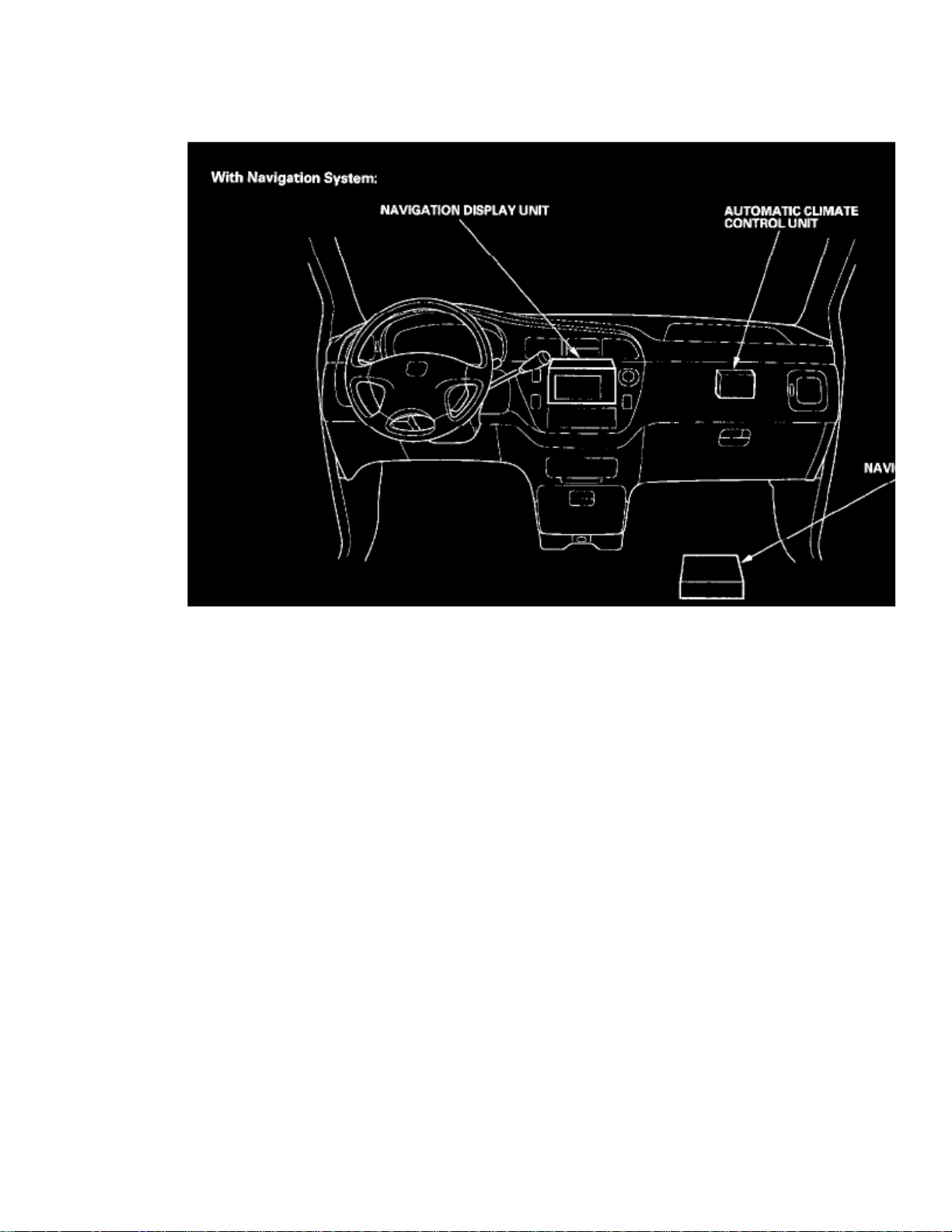
Navigation Module: Locations
Dashboard - With Navigation System
Page 79

> Relays and Modules > Relays and Modules - Accessories and Optional Equipment > Navigation Module > Component Information > Technical Service Bulletins > Page 68
Odyssey LX V6-3.5L (2000)
Page 80

Relay And Control Unit Locations - Dashboard
Page 81

> Relays and Modules > Relays and Modules - Accessories and Optional Equipment > Navigation Module > Component Information > Technical Service Bulletins > Page 69
Odyssey LX V6-3.5L (2000)
Page 82

Navigation System Component Location Index
Page 83

Page 84

> Relays and Modules > Relays and Modules - Accessories and Optional Equipment > Navigation Module > Component Information > Technical Service Bulletins > Page 70
Page 85

Page 86

> Relays and Modules > Relays and Modules - Accessories and Optional Equipment > Navigation Module > Component Information > Technical Service Bulletins > Page 71
Navigation Module: Service and Repair
Navigation Unit Removal/Installation
1. Remove the navigation unit guard (A) from the bracket.2. Remove the navigation unit bracket (B) from the passenger's seat.3. Remove the navigation unit (C) from the bracket.4. Install the parts in the reverse order of removal.
Install the navigation unit guard with the arrow (D) pointing up.NOTE:
5. Perform After servicing Procedures.
Page 87

Page 88

> Relays and Modules > Relays and Modules - Accessories and Optional Equipment > Vehicle Speed Interface Module > Component Information > Service and Repair
Vehicle Speed Interface Module: Service and Repair
Vehicle Speed Pulse (VSP) Sensor Replacement
1. Disconnect the 3P connector (A) from the vehicle speed pulse (VSP) sensor (B).2. Remove the mounting bolt (C), then remove the VSP.3. Install the VSP Lubricate the new O-ring (D) and the vehicle speed pulse (VSP) sensor joint (E) with grease before installing.
Page 89

Page 90

> Relays and Modules > Relays and Modules - Body and Frame > Fuel Door Release Relay > Component Information > Locations
Fuel Door Release Relay: Locations
Behind Left Rear Side Trim Panel
Page 91

> Relays and Modules > Relays and Modules - Body and Frame > Fuel Door Release Relay > Component Information > Locations > Page 79
Odyssey LX V6-3.5L (2000)
Page 92
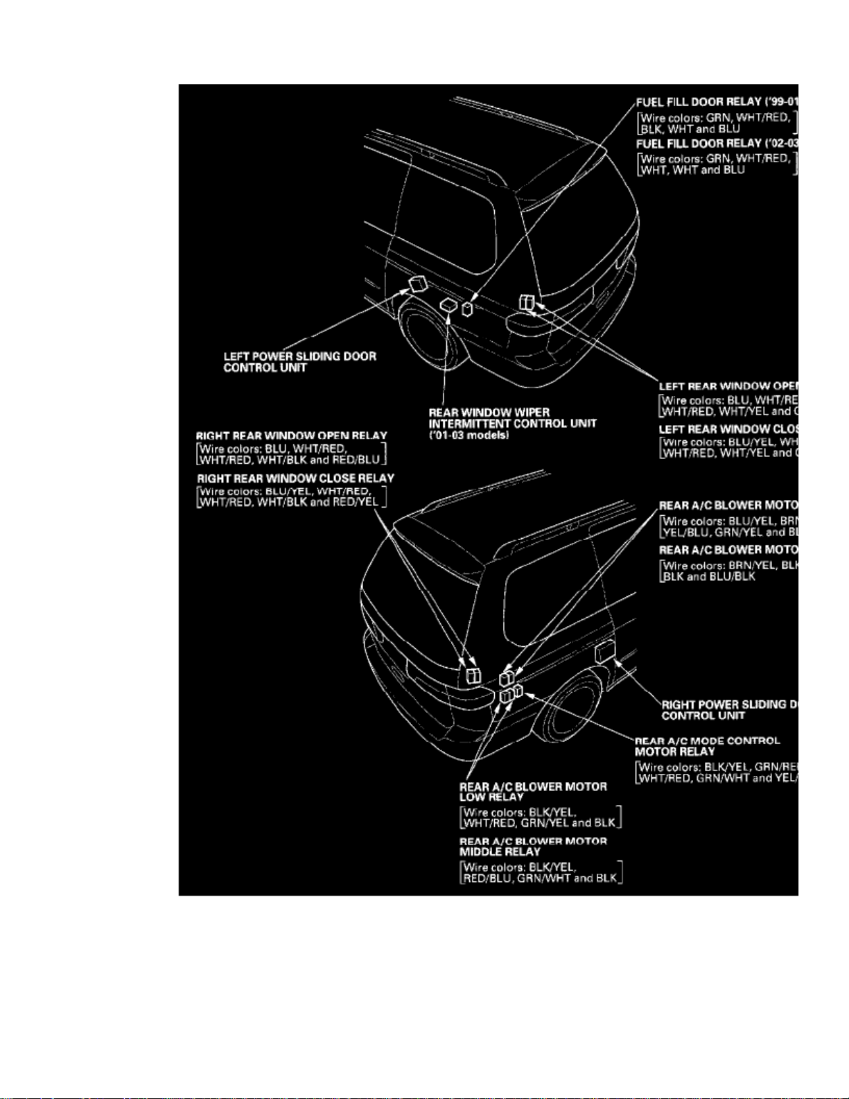
Relay And Control Unit Locations - Rear Side Trim
Page 93

Page 94

> Relays and Modules > Relays and Modules - Body and Frame > Fuel Door Release Relay > Component Information > Locations > Page 80
Page 95

Page 96

> Relays and Modules > Relays and Modules - Body and Frame > Fuel Door Release Relay > Component Information > Locations > Page 81
Fuel Door Release Relay: Testing and Inspection
Power Relay Test
Use this chart to identify the type of relay, then do the test listed for it.
The turn signal/hazard relay input test.NOTE:
Five-terminal type B:
Page 97

> Relays and Modules > Relays and Modules - Body and Frame > Fuel Door Release Relay > Component Information > Locations > Page 82
Odyssey LX V6-3.5L (2000)
Page 98

Check for continuity between the terminals.
- There should be continuity between the No.1 and No.2 terminals when power and ground are connected to the No.3 and No.5 terminals.
- There should be continuity between the No.1 and No.4 terminals when power is disconnected.
Page 99

Page 100
> Relays and Modules > Relays and Modules - Body and Frame > Keyless Entry Module > Component Information > Locations
Keyless Entry Module: Locations
Right Dashboard View
 Loading...