

Honda in-VEHICLE ENTERTAINMENT SYSTEM 08A60-S0X-100 Installation Instructions Manual
INSTALLATION
http://www.HandA-Accessories.com
INSTRUCTIONS
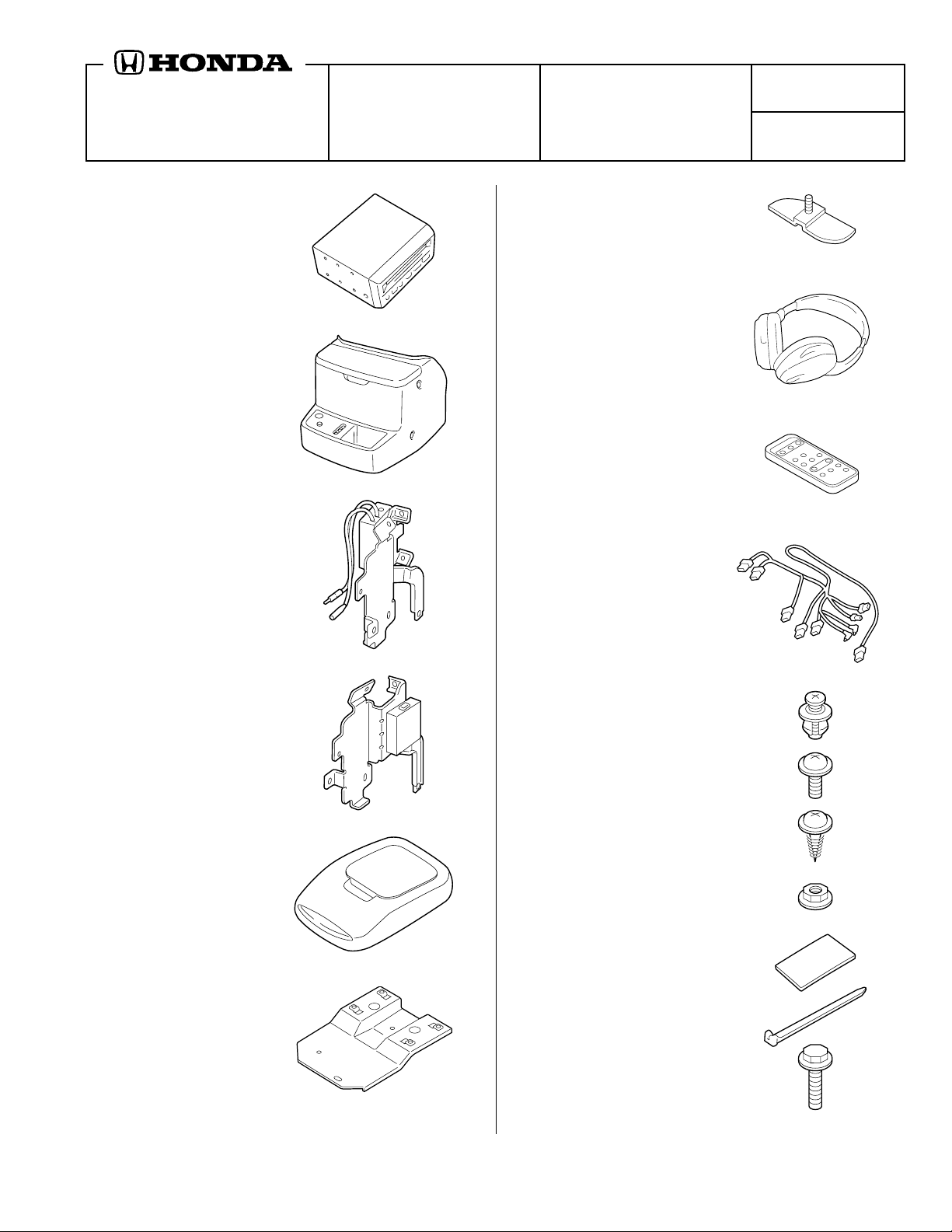
PARTS LIST
VCP
(Video Cassette Player)
VCP console
Accessory Application Publications No.
in
-VEHICLE
ENTERTAINMENT SYSTEM
(i-VES)
P/N 08A60-S0X-100
ODYSSEY
Butterfly bracket
2 Headphones
(AAA batteries not included)
Remote control
AII 22054
Issue Date
APRIL 2001
Right VCP bracket
Left VCP bracket
Monitor console
Wire harness
4 Console clips
2 Washer-screws, 5 x 14 mm
4 Self-tapping-screws, 4 x 19 mm
Lock nut
Cushion tape
Monitor bracket
© 2001 American Honda Motor Co., Inc - All Rights Reserved. AII 22054 (0104) 1 of 14
10 Wire ties
2 Bolts, 8 x 25 mm
Y0581D3
08Z03-S0X-1A00-91
2 Flange nuts, 8 mm
Template
4 Screws, 4 x 10 mm
INSTALLATION
Customer Information: The information in this
installation instruction is intended for use only by
skilled technicians who have the proper tools,
equipment, and training to correctly and safely add
equipment to your vehicle. These procedures
should not be attempted by “do-it-yourselfers.”
4 Plain-washers, 8 mm
2 Sponge pads
Owner's manual
TOOLS AND SUPPLIES REQUIRED
Phillips screwdriver
Flat-tip screwdriver
Ratchet
7 mm, 8 mm, 12 mm, 13 mm, and 14 mm Sockets
10 mm Deep socket
Torx bit (T25)
Torque wrench
Utility knife
Masking tape
Electrical tape
Shop towel
Scissors
Piece of wire about 3 ft long
Flat-tip pen
Illustration of the
i-VES
Installed on the Vehicle
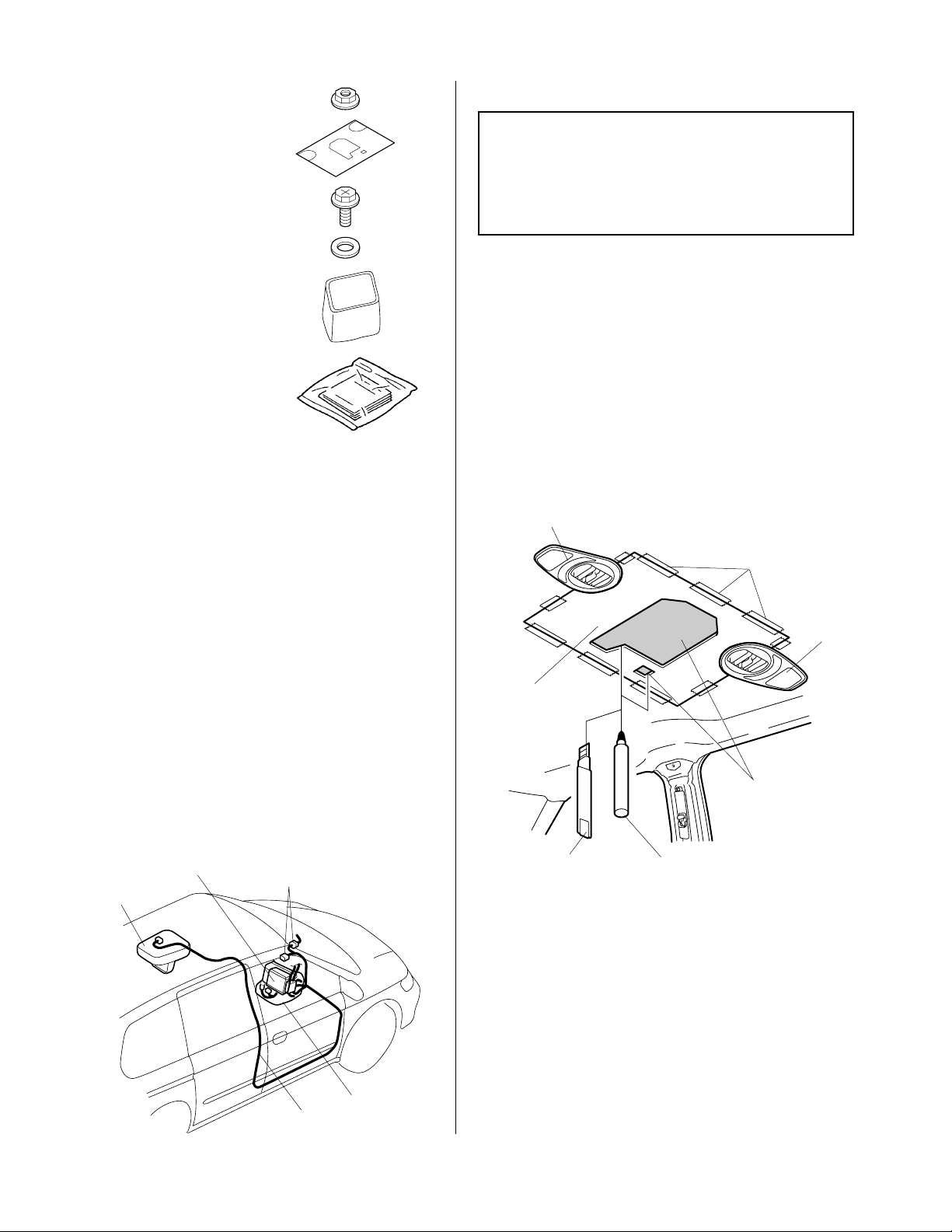
1. If equipped, make sure you have the anti-theft
code for the radio, then wr ite down the
frequencies for the preset buttons.
2. Disconnect the negative cable from the battery.
3. Get the roof template. Using scissors, cut out
the center of the roof template.
4. Position the template on the headliner, and
secure it with masking tape. Mark the headliner
as indicated on the template with a felt-tip pen
(two places).
FRONT VENT
Strip of
masking tape
FRONT
VENT
TEMPLATE
Cut out the marked
area from the
headliner.
MONITOR
CONSOLE
VCP
20-PIN CONNECTORS
UTILITY
KNIFE
FEL T-TIP PEN
5. Remove the template. Using a utility knife, cut
out the marked areas of the headliner. Remove
and discard the cut pieces of the headliner and
the insulation.
VCP
i-VES HARNESS
2 of 14 AII 22054 (0104) © 2001 American Honda Motor Co., Inc - All Rights Reserved.
CONSOLE
6. Remove the center panel:
• Move the gear selector to the D1 position.
• Using a small flat-tip screwdriver wrapped
with a shop towel, gently pry out and remove
the plastic cover.
• Reach inside the cover hole, and gently pull
along the bottom to release the lower clips;
then work toward the top to release all 10
clips.
• Pull out the console panel, unplug the
connectors and remove it.
Without Navigation Unit:
CONNECTORS
7. Remove the radio (four bolts, and unplug the
radio connector and the antenna lead). If
equipped, remove the navigation unit (six
screws, and unplug the connectors and the
antenna lead).
Without Navigation Unit:
ANTENNA LEAD
CLIP
RADIO
CONNECTOR
SMALL
FLAT -TIP
SCREWDRIVER
With Navigation Unit:
NA VIGA TION UNIT
PLASTIC
COVER
CONNECTORS
TAB
CONSOLE
PANEL
CLIP
With Navigation Unit:
CONNECTORS
ANTENNA
LEAD
BOLTS
NA VIGA TION UNIT
SCREWS
SCREW
TAB
CONSOLE
PANEL
© 2001 American Honda Motor Co., Inc - All Rights Reserved. AII 22054 (0104) 3 of 14
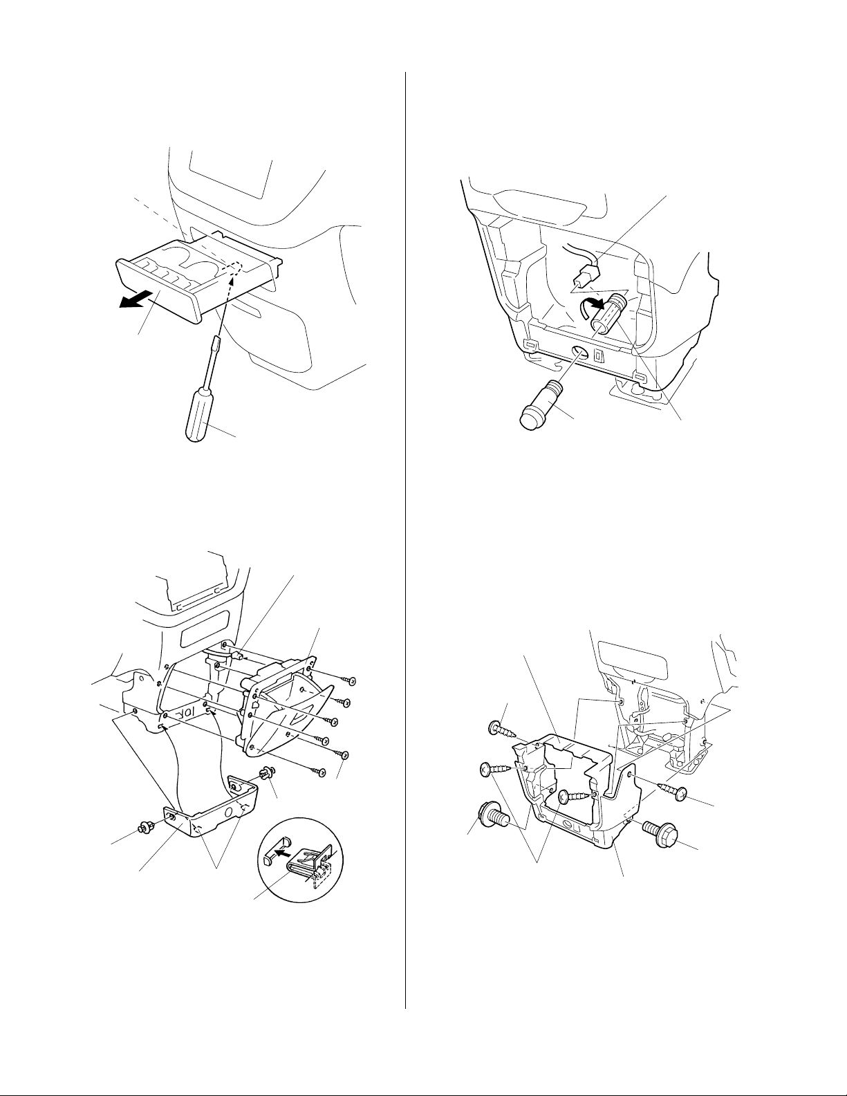
8. Open the cup holder. Using a flat-tip screwdriver,
push up on the retaining tab at the bottom, and
slide the cup holder out.
11. Disconnect the accessory socket from the
accessory socket harness connector, then
remove the socket from the instrument panel by
unscrewing the socket from the socket holder.
Push up
on the
retaining
tab.
CUP
HOLDER
FLAT -TIP
SCREWDRIVER
9. Remove the center lower trim (one clip on each
side, and two clips on the front).
CONNECTOR
(EX Model only)
CENTER
LOWER
POCKET
ACCESSOR Y SOCKET
HARNESS CONNECTOR
ACCESSORY
SOCKET
(Reuse.)
SOCKET
HOLDER
(Reuse.)
If the vehicle you are working on is equipped with
a navigation unit, continue with step 12;
otherwise, go to step 14.
12. Remove the center lower console (four screws
and two bolts).
CENTER LOWER
CONSOLE
SCREW
SELFTAPPING
SCREWS (6)
BOLT
(Discard.)
SCREWS
SCREW
BOLT
(Discard.)
CENTER LOWER
CONSOLE
CLIP
CENTER LOWER
TRIM
CLIP
CLIPS
CLIP
10. Open the center lower pocket, and remove the
six self-tapping screws. Disconnect the
connector (if equipped), and remove the center
lower pocket.
4 of 14 AII 22054 (0104) © 2001 American Honda Motor Co., Inc - All Rights Reserved.
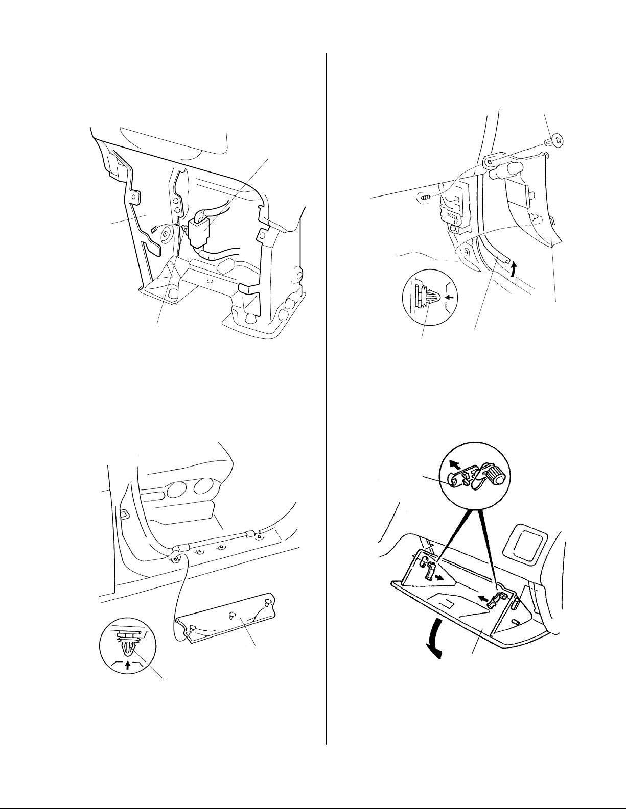
13. Remove the vehicle harness connector from the
body frame by releasing its clip from the hole in
the body frame.
VEHICLE
HARNESS
CONNECTOR
BODY
FLAME
CLIP
15. Peel up the door opening trim, and remove the
passenger's kick panel (one screw and one clip).
SCREW
PASSENGER'S
KICK P ANEL
CLIP
PASSENGER'S
DOOR OPENING
TRIM
14. On the passenger's side of the vehicle, remove
the front door side sill trim (lift up to release the
three clips).
PASSENGER'S
FRONT DOOR SIDE
SILL TRIM
CLIP (3)
16. Lower the glove box by removing the right and
left stoppers.
STOPPER
Lower
completely .
GLOVE
BOX
© 2001 American Honda Motor Co., Inc - All Rights Reserved. AII 22054 (0104) 5 of 14
 Loading...