

Page 1
Owner’s Manual
Click to Save As
SNOW BLOWER
HSS724A
00X31V45 A040
Page 2

INTRODUCTION
Congratulations on your selection of a Honda snow blower! We are
certain you will be pleased with your purchase of one of the finest
snow blowers on the market.
We want to help you get the best results from your new snow blower
and to operate it safely. This manual contains the information on how
to do that; please read it carefully.
As you read this manual, you will find information preceded by a
symbol. That information is intended to help you avoid damage
to your snow blower, other property, or the environment.
We suggest you read the warranty policy to fully understand its
coverage and your responsibilities of ownership. The warranty policy is
located in the back of this manual.
When your snow blower needs scheduled maintenance, keep in mind
that your Honda servicing dealer is specially trained in servicing Honda
snow blowers. Your Honda servicing dealer is dedicated to your
satisfaction and will be pleased to answer your questions and
concerns.
Best Wishes,
American Honda Motor Co., Inc.
1
Page 3
INTRODUCTION
A FEW WORDS ABOUT SAFETY
Your safety and the safety of others are very important. And using this
snowblower safely is an important responsibility.
To help you make informed decisions about safety, we have provided
operating procedures and other information on labels and in this
manual. This information alerts you to potential hazards that could hurt
you or others.
Of course, it is not practical or possible to warn you about all the
hazards associated with operating or maintaining a snow blower. You
must use your own good judgment.
You will find important safety information in a variety of forms,
including:
• Safety Labels — on the snow blower.
• Safety Messages — preceded by a safety alert symbol and one of
three signal words, DANGER, WARNING, or CAUTION.
These signal words mean:
You WILL be KILLED or SERIOUSLY HURT if
you don’t follow instructions.
You CAN be KILLED or SERIOUSLY HURT if
you don’t follow instructions.
You CAN be HURT if you don’t follow
instructions.
• Safety Headings — such as IMPORTANT SAFETY INFORMATION.
• Safety Section — such as SNOW BLOWER SAFETY.
• Instructions — how to use this snow blower correctly and safely.
This entire book is filled with important safety information — please
read it carefully.
2
Page 4

CONTENTS
SNOW BLOWER SAFETY ............................................................5
IMPORTANT SAFETY INFORMATION ........................................5
SAFETY LABEL LOCATIONS.....................................................8
INITIAL USE INSTRUCTIONS .......................................................9
CONTROLS & FEATURES .......................................................... 12
COMPONENT & CONTROL LOCATIONS................................... 12
CONTROLS .......................................................................... 12
Fuel Valve Lever ................................................................ 15
Engine Switch....................................................................14
Starter Grip ....................................................................... 15
Throttle Lever ....................................................................16
Shift Lever ........................................................................ 17
Chute Joystick Control .......................................................17
Drive Clutch Lever and Auger Clutch Lever............................ 18
Steering Controls ............................................................... 19
FEATURES ........................................................................... 22
Snow Clearing Bar.............................................................. 22
BEFORE OPERATION ................................................................23
ARE YOU READY TO GET STARTED?......................................23
IS YOUR SNOWBLOWER READY TO GO? ................................ 23
Check the General Condition of the Snowblower.................... 24
Check the Engine ...............................................................24
CHECK YOUR WORK AREA.................................................... 25
OPERATION.............................................................................26
SNOWBLOWING PRECAUTIONS ............................................. 26
STARTING THE ENGINE ......................................................... 27
STOPPING THE ENGINE ......................................................... 30
CLEARING SNOW ................................................................. 33
SNOW-CLEARING TIPS ..........................................................35
REMOVING OBSTRUCTIONS .................................................. 36
SERVICING YOUR SNOWBLOWER..............................................37
THE IMPORTANCE OF MAINTENANCE .................................... 37
MAINTENANCE SAFETY ........................................................37
TOOL KIT ............................................................................. 39
MAINTENANCE SCHEDULE .................................................... 40
REFUELING........................................................................... 42
FUEL RECOMMENDATIONS.................................................... 43
3
Page 5

CONTENTS
SERVICING YOUR SNOWBLOWER (continued)
ENGINE OIL LEVEL CHECK .....................................................44
ENGINE OIL CHANGE ............................................................ 45
ENGINE OIL RECOMMENDATIONS .......................................... 46
SPARK PLUG SERVICE...........................................................47
TRACK ADJUSTMENT ........................................................... 49
TIRE INSPECTION.................................................................. 50
AUGER AND BLOWER INSPECTION......................................... 50
SHEAR BOLT REPLACEMENT PROCEDURE............................... 51
SKID SHOES AND SCRAPER .................................................. 52
STORAGE................................................................................ 54
STORAGE PREPARATION....................................................... 54
Cleaning............................................................................ 54
Fuel.................................................................................. 55
Engine Oil.......................................................................... 58
Tires.................................................................................58
STORAGE PRECAUTIONS ......................................................62
REMOVAL FROM STORAGE ...................................................62
TRANSPORTING ...................................................................... 63
BEFORE LOADING ................................................................. 63
LOADING ............................................................................. 64
TAKING CARE OF UNEXPECTED PROBLEMS ............................... 66
ENGINE PROBLEMS ............................................................... 66
DRIVE PROBLEMS.................................................................67
SNOWBLOWER PROBLEMS .................................................... 67
TECHNICAL INFORMATION ....................................................... 69
Serial Number Locations...................................................... 69
Carburetor Modification for High Altitude Operation................ 70
Emission Control System Information.................................... 71
Air Index ........................................................................... 73
Specifications .................................................................... 74
CONSUMER INFORMATION....................................................... 75
Dealer Locator Information ..................................................75
Honda Publications ............................................................. 75
Customer Service Information .............................................. 76
DISTRIBUTOR WARRANTY........................................................78
EMISSION WARRANTY.............................................................80
4
Page 6

SNOW BLOWER SAFETY
IMPORTANT SAFETY INFORMATION
Honda snow blowers are designed to clear snow from driveways and
walkways. Other uses can result in injury to the operator or damage to
the snow blower and other property.
Most injuries or property damage with snow blowers can be prevented
if you follow all instructions in this manual and on the snow blower.
The most common hazards, are discussed below, along with the best
way to protect yourself and others.
Avoid Rotating Impeller and Auger
Hand contact with the rotating impeller inside the discharge chute is
the most common cause of injury associated with snow blowers. The
snow blower auger can also cause serious injury. Keep away from the
impeller and auger whenever the engine is running. If you need to work
around the snow blower to clear snow for any reason, always shut off
the engine. If the snow discharge chute becomes clogged, stop the
engine and disconnect the spark plug cap. Use the snow clearing bar or
a wooden stick to remove the obstructions. Never put your hand into
the snow discharge chute while the engine is running; serious personal
injury could result.
Clear Operation Area
The snow blower can throw rocks and other objects with enough force
to cause serious injury. Before operating the snow blower, carefully
inspect the area and remove any visible stones, sticks, news papers,
nails, pieces of wire, and other loose objects. Never use the snow
blower to clear snow from a gravel road or driveway, as rocks may be
picked up and ejected. They may cause injury to bystanders.
5
Page 7

SNOW BLOWER SAFETY
Keep Shields in Place
Guards and shields are designed to protect you from being hit by
thrown objects and to keep you from touching hot engine parts and
moving components. For your safety and the safety of others, keep all
shields in place when the engine is running.
Adjust the snow discharge chute to avoid hitting the operator,
bystanders, windows, and other objects with ejected snow. Stay clear
of the snow discharge chute while the engine is running.
Children and pets must be kept away from the area of operation to
avoid injury from flying debris and contact with the snow blower.
Refuel with Care
Gasoline is extremely flammable, and gasoline vapor can explode.
Allow the engine to cool if the snow blower has been in operation.
Refuel only outdoors in a well-ventilated area with the engine OFF. Do
not overfill the fuel tank. Never smoke near gasoline, and keep other
flames and sparks away. Always store gasoline in an approved
container. Make sure that any spilled fuel has been wiped up before
starting the engine.
Turn Engine OFF When Not Operating the Snow blower
If you need to leave the snow blower for any reason, even just to
inspect the area ahead, always turn the engine off.
Operation on Slopes
Do not use the snow blower on a slope greater than 20 degrees.
To avoid overturning, be careful when changing the direction of the
snow blower while operating it on a slope. Do not use the snow blower
to remove snow from angled roof tops. The snow blower may overturn
on steep slopes if left unattended, causing injury to the operator or
bystanders.
6
Page 8

SNOW BLOWER SAFETY
Operating Conditions
Do not use the snow blower when visibility is poor. Under conditions of
poor visibility, there is a greater risk of striking an obstacle or causing
injury. Adjust the snow discharge chute to avoid hitting bystanders or
vehicles.
Stay clear of the snow discharge chute while the engine is running and
be aware that loose clothing can get drawn into the moving parts.
Operating Near Roads
Always watch for vehicle traffic when operating the snow blower near
roads and driveways.
Operator Responsibility
Know how to stop the snow blower quickly in case of emergency.
Understand the use of all snow blower controls.
Never permit anyone to operate the snow blower without proper
instruction. Do not let children operate the snow blower. If people or
pets suddenly appear in front of the snow blower while it is in
operation, immediately release the auger and drive clutch levers to stop
the snow blower and avoid possible injury from rotating auger blades.
While operating the snow blower, hold the handle firmly and walk,
don’t run. Wear suitable winter boots that resist slipping.
Wear safety glasses or eye shields during operation to protect eyes
from thrown objects.
Exercise caution on slippery surfaces to avoid falling, especially when
operating in reverse.
7
Page 9
SNOW BLOWER SAFETY
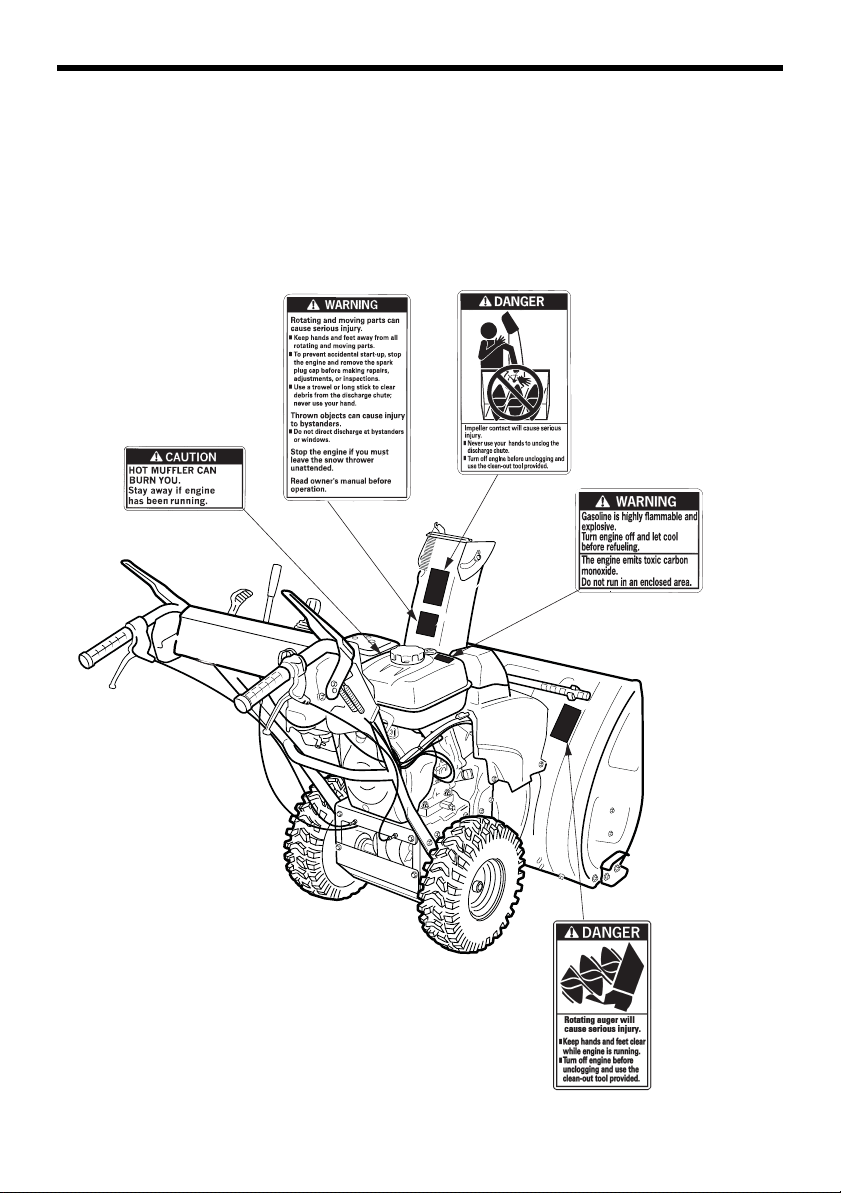
SAFETY LABEL LOCATIONS
These labels warn you of potential hazards that can cause serious
injury. Read them carefully.
If a label comes off or becomes hard to read, contact your Honda snow
blower dealer for a replacement.
8
Page 10
INITIAL USE INSTRUCTIONS
!
"
#
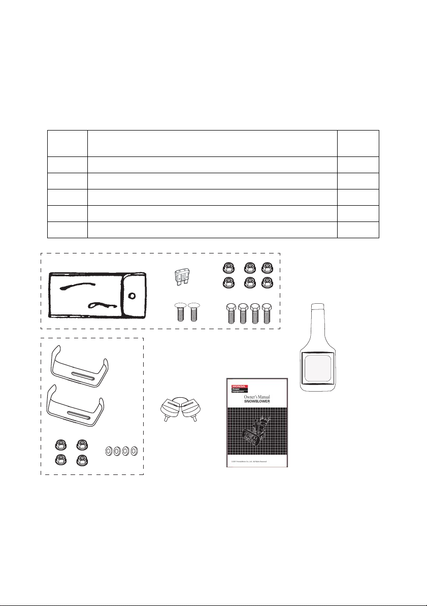
LIST OF LOOSE PARTS
Remove the loose parts carton and compare the loose parts against the
following list. Contact an authorized Honda dealer from whom you
purchased the snow blower if any of the loose parts shown are not
included with your snow blower.
Ref
No.
Tool kit (see page 39) 1
Bottle of oil (16 oz) 1
Skid shoes (AW, AWD) (see page 52) 2
Ignition key 2
Owner’s manual 1
Description Qty.
9
Page 11
INITIAL USE INSTRUCTIONS
ADD ENGINE OIL The snow blower is shipped WITHOUT OIL in the engine.
UPPER LIMIT
LOWER LIMIT
OIL FILLER CAP
1.With the snow blower on a level surface, remove the oil filler cap/
dipstick.
2.Add oil from the included bottle of oil into the oil filler opening to the
top of the filler opening (upper limit).
All Honda engines are run at the factory prior to packaging. Most of
the oil is removed prior to shipment; however, some oil remains in
the engine. The amount of oil left in the engine varies.
3.If you don’t use the supplied oil, add enough recommended oil
(page 46) to bring the oil level to the top of the oil filler opening.
4.Do not overfill the engine with oil. After filling the engine with oil,
screw the filler cap/dipstick in and remove the hang tag near the
recoil starter grip that says “The engine has no oil”.
10
Page 12

INITIAL USE INSTRUCTIONS
PLEASE REGISTER YOUR SNOW BLOWER
Please take a few minutes and register your purchase with Honda. You
can register:
• By completing and mailing the registration card on the inside of this
book
• Going online to powerequipment.honda.com
and clicking on Production Registration shown
at the bottom of the page.
• By scanning the QR code to the right and completing the online form
BEFORE USING YOUR SNOW BLOWER
All snow blower operators must read the following sections:
• SNOW BLOWER SAFETY (page 5)
• BEFORE OPERATION (page 23)
• OPERATION (page 28)
• MAINTENANCE SCHEDULE (page 40)
11
Page 13
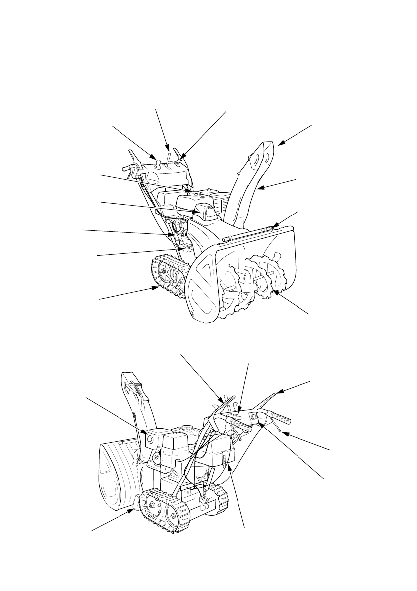
CONTROLS & FEATURES
CHUTE GUIDE
FUEL TANK CAP
CHUTE JOYSTICK
CONTROL
THROTTLE/ CHOKE LEVER
SHIFT LEVER
TRACK
AUGER
STEERING
CONTROL
LEVER (2)
LED WORK LIGHT
SNOW DISCHARGE
CHUTE
SNOW CLEARING BAR
SKID
BATTERY
(ATD)
ENGINE
SWITCH
MUFFLER
DRIVE CLUTCH LEVER
<TRACK TYPE
AT, ATD>
AUGER CLUTCH
LEVER
HEIGHT ADJUST LEVER
ENGINE OIL
FILLER CAP
ENGINE SERIAL
NUMBER
COMPONENT & CONTROL LOCATIONS
Use the illustrations on these pages to locate and identify the most
frequently used controls.
12
Page 14
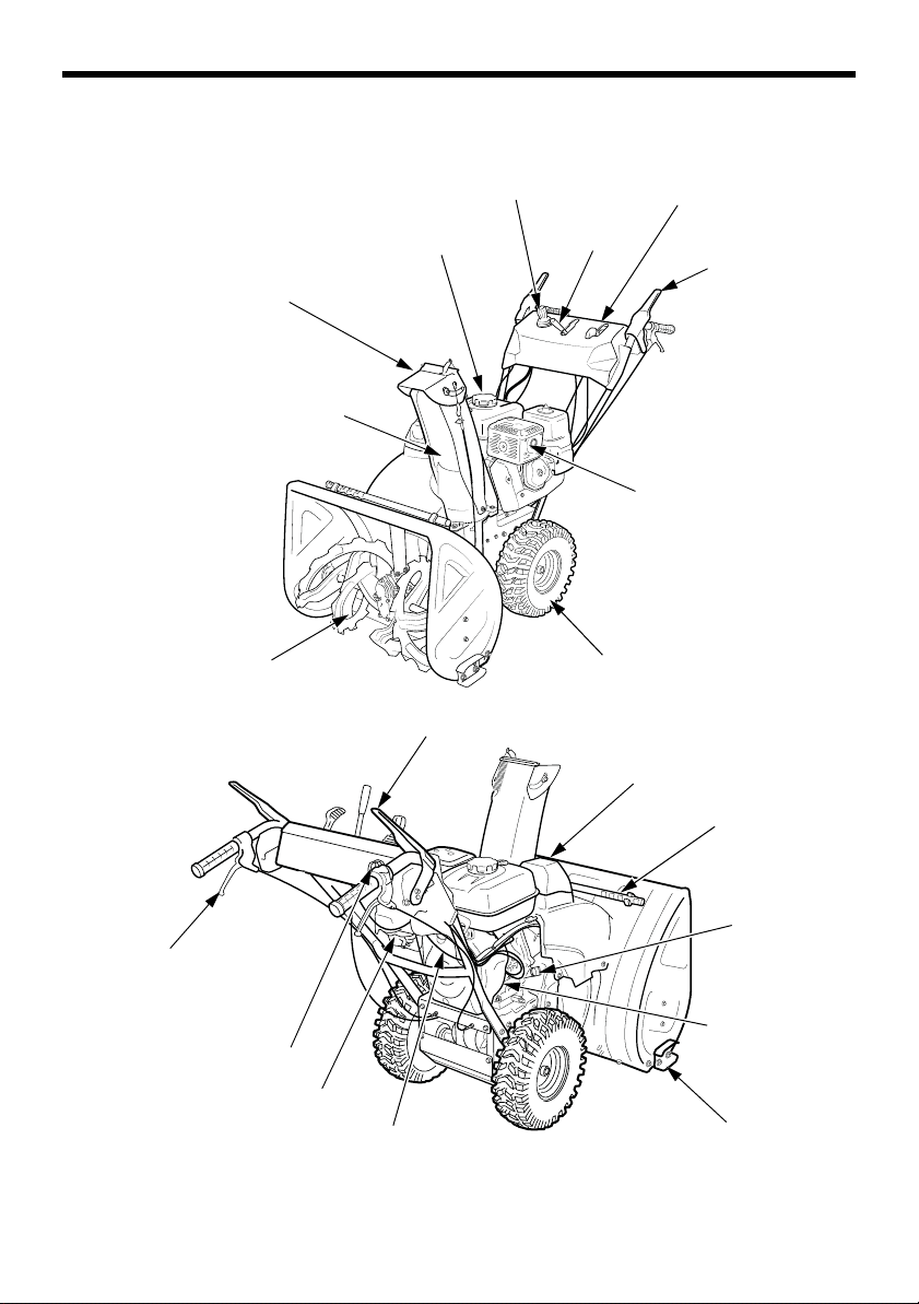
CONTROLS & FEATURES
CHUTE GUIDE
FUEL TANK CAP
JOYSTICK CHUTE CONTROL
SHIFT
LEVER
THROTTLE/ CHOKE LEVER
DRIVE CLUTCH
LEVER
MUFFLER
WHEEL
AUGER
AUGER CLUTCH LEVER
LED WORK LIGHT
SNOW DISCHARGE CHUTE
FUEL VALVE
STARTER GRIP
SNOW CLEARING BAR
ENGINE OIL
FILLER CAP
ENGINE SERIAL
NUMBER
SKID
<WHEEL TYPE
AW, AWD>
STEERING
CONTROL
LEVER (2)
ENGINE SWITCH
13
Page 15
CONTROLS & FEATURES
RECOIL ENGINE SWITCH
ONOFF
DC ELECTRIC ENGINE SWITCH
ONOFF
START
CONTROLS
Engine Switch
The engine switch controls the
ignition system. The key can only
be inserted and removed when
turned to OFF.
(Recoil Starter AT, AW)
OFF – Stops the engine.
ON – Running position, and for
starting with the recoil starter.
(Electric Starter ATD, AWD)
OFF – Stops the engine.
ON – Running position, and for
starting with the recoil starter.
START - Use this position to start
the engine with the DC starter. The
switch returns to the ON position
when you let go of the key.
14
Page 16
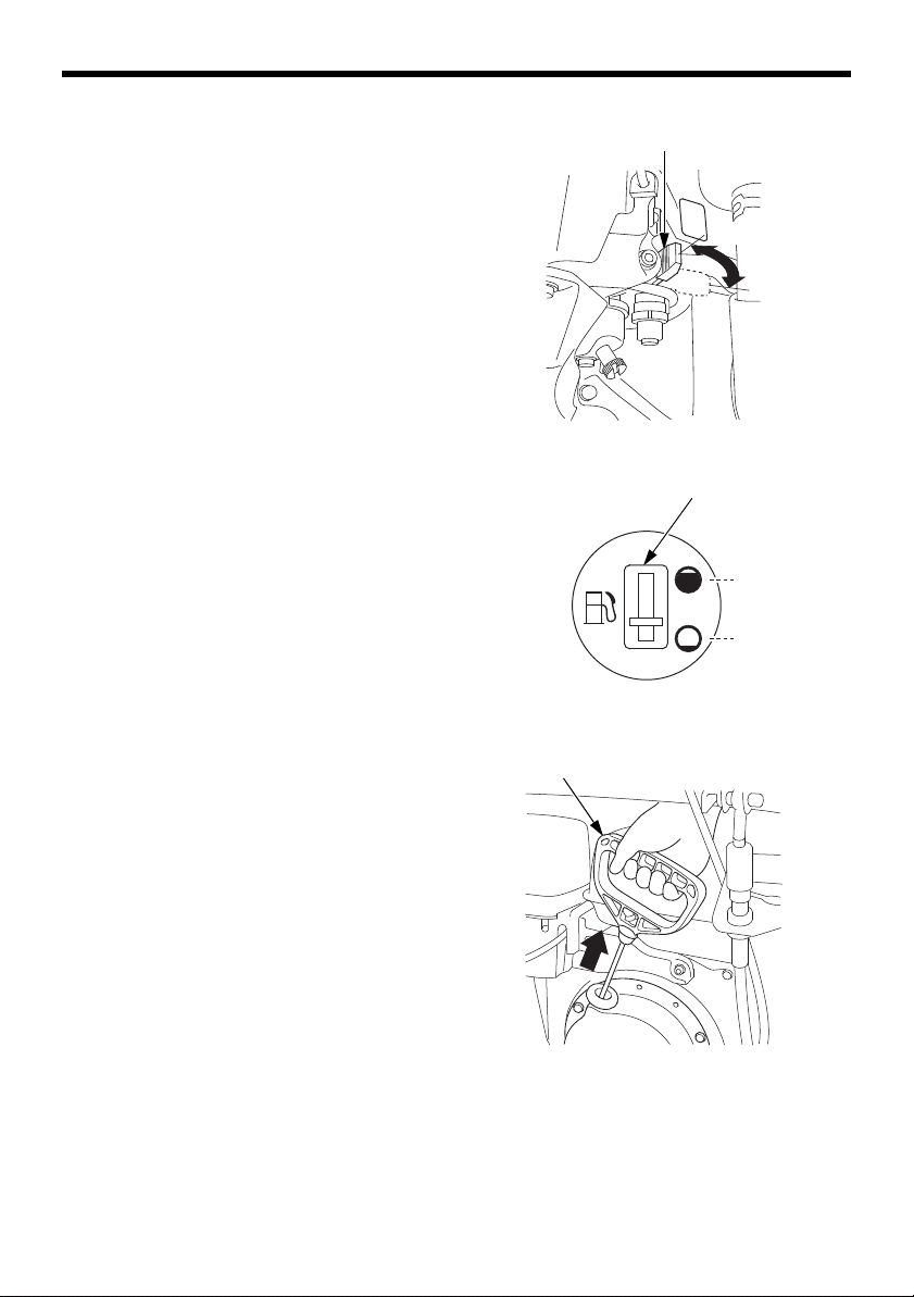
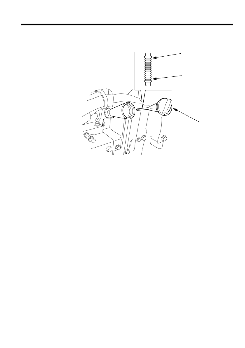
Fuel Valve Lever
ON
OFF
FUEL VALVE LEVER
FULL
EMPTY
FUEL GAUGE
STARTER GRIP
The fuel valve opens and closes
the fuel line leading from the fuel
tank to the carburetor. Make sure
that the fuel valve is positioned
exactly at either the ON or OFF
position. When the snow blower
is not in use, always leave the fuel
valve in the OFF position to
reduce the possibility of fuel
leakage.
Fuel Gauge
The fuel gauge indicates the
amount of fuel in the tank. When
the fuel gauge needle enters the
EMPTY position, refill the tank as
soon as possible.
CONTROLS & FEATURES
Starter Grip
Pull this grip to start the engine.
See page 27 for starting
procedures.
15
Page 17
CONTROLS & FEATURES
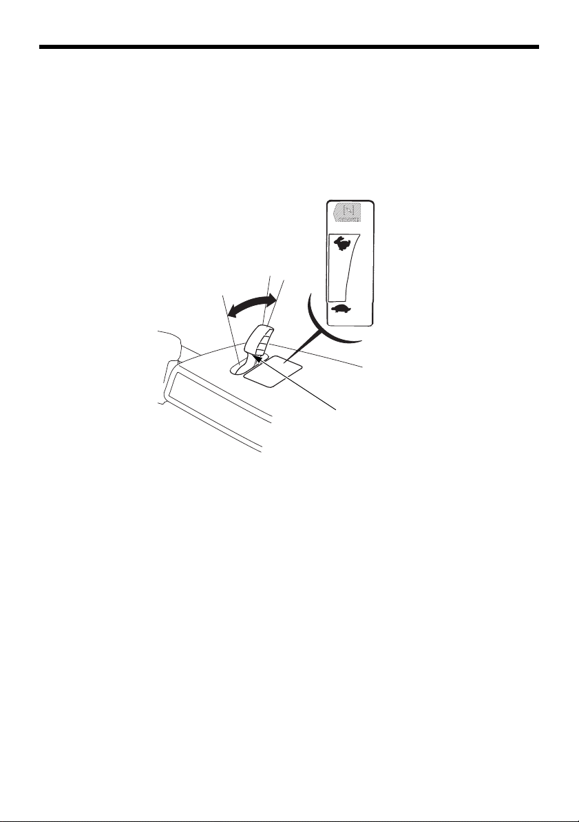
FAST
SLOW
THROTTLE LEVER
FAST
SLOW
CHOKE
Throttle Lever
The throttle lever controls engine speed from SLOW to FAST to
CHOKE, it will stay in any designated position.
NOTE: For best snow blowing performance, keep the throttle lever in
the FAST position.
FAST
SLOW
16
Page 18
CONTROLS & FEATURES
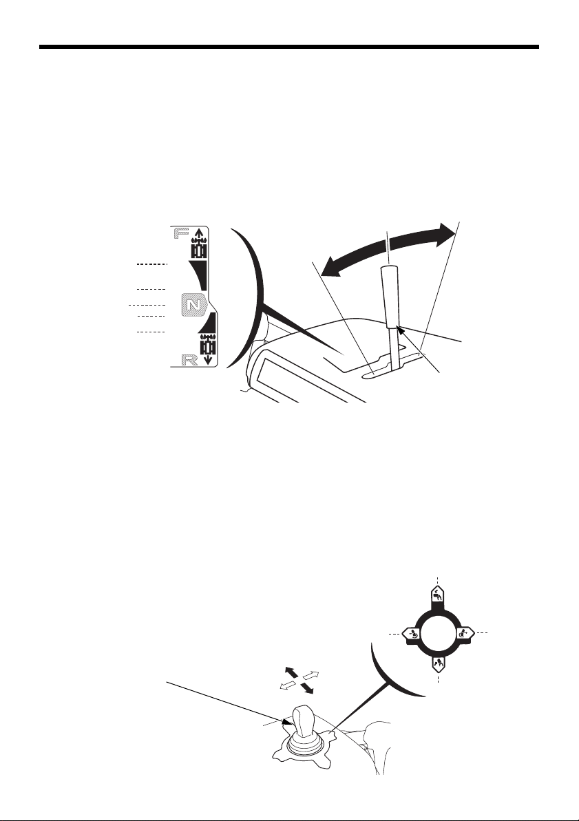
‘‘N’’ (Neutral)
FORWARD
REVERSE
FORWARD
FAST
SLOW
NEUTRAL
SLOW
FAST
REVERSE
SHIFT LEVER
DOWN
DOWN
LEFT
RIGHT
UP
CHUTE JOYSTICK CONTROL
UP
LEFT
RIGHT
Shift Lever
Forward and reverse directions can be selected by shifting this lever; it
will also remain in any designated position. Actual movement of the
snow blower will take effect when the drive clutch lever is engaged.
Set the lever in ‘‘N’’ (Neutral) when the snow blower is not in use.
Chute joystick control
Use the joystick control to turn the snow discharge chute right or left
and up or down.
The engine must be running to operate the chute joystick control.
Chute movement speed will increase with engine speed. For maximum
speed, move the throttle to the fastest position when using the chute
joystick.
17
Page 19
CONTROLS & FEATURES
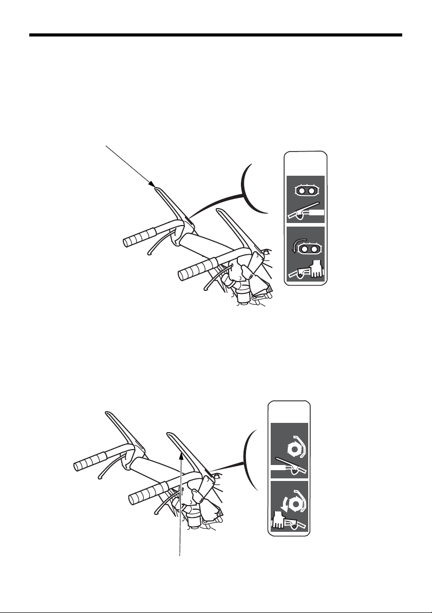
ENGAGED
DISENGAGED
DRIVE CLUTCH LEVER
ENGAGE
DISENGAGE
AUGER
CLUTCH
DISENGAGED
ENGAGED
AUGER CLUTCH LEVER
Drive clutch lever
Depress the drive clutch lever to move the snow blower forward or
backward based on the position of the shift lever (see previous page).
If the snow blower is to be transported, depress the drive clutch lever
without the auger clutch lever.
DRIVE
CLUTCH
DISENGAGE
ENGAGE
Auger clutch lever
Depress the auger clutch lever to start the snow blowing mechanism. If
the drive clutch lever is engaged, the auger clutch lever will lock
engaged when it is depressed. However, the auger clutch lever will
unlock when the drive clutch lever is released.
18
Page 20
CONTROLS & FEATURES
DRIVE CLUTCH LEVER
LOCKED
Both levers depressed
The auger clutch lever remains locked
down as long as one hand continues
to depress the drive clutch lever.
LEFT STEERING
CONTROL LEVER
RIGHT STEERING
CONTROL LEVER
When both levers are depressed, the drive clutch lever locks the auger
clutch lever down. Releasing the drive clutch lever then unlocks and
releases the auger clutch lever.
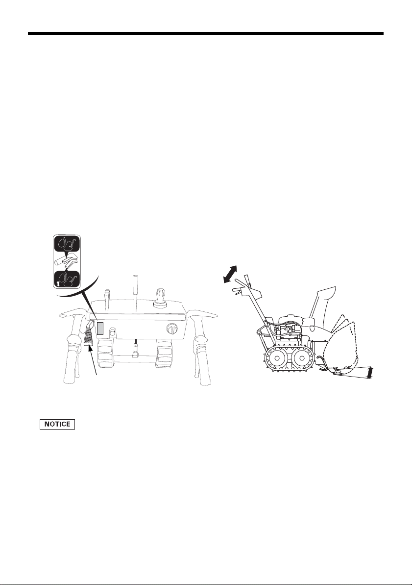
Steering controls
When both steering control levers are released, the snow blower will
advance in a straight line in either a forward or reverse direction
depending on the position of the shift lever.
19
Page 21
CONTROLS & FEATURES
LEFT TURN
RIGHT TURN
Pull the left steering control lever against the handlebar to turn the
snow blower to the left.
Pull the right steering control lever against the handlebar to turn the
snow blower to the right.
NOTE:
Do not partially engage or release the steering control levers. Always
fully engage or fully release the levers.
Pull both steering control levers at the same time to momentarily
disengage the transmission. With the transmission disengaged, the
snow blower is free to maneuver (push or pull) by hand with or without
the engine running.
20
Page 22
CONTROLS & FEATURES
HEIGHT ADJUST LEVER
HIGH
LOW
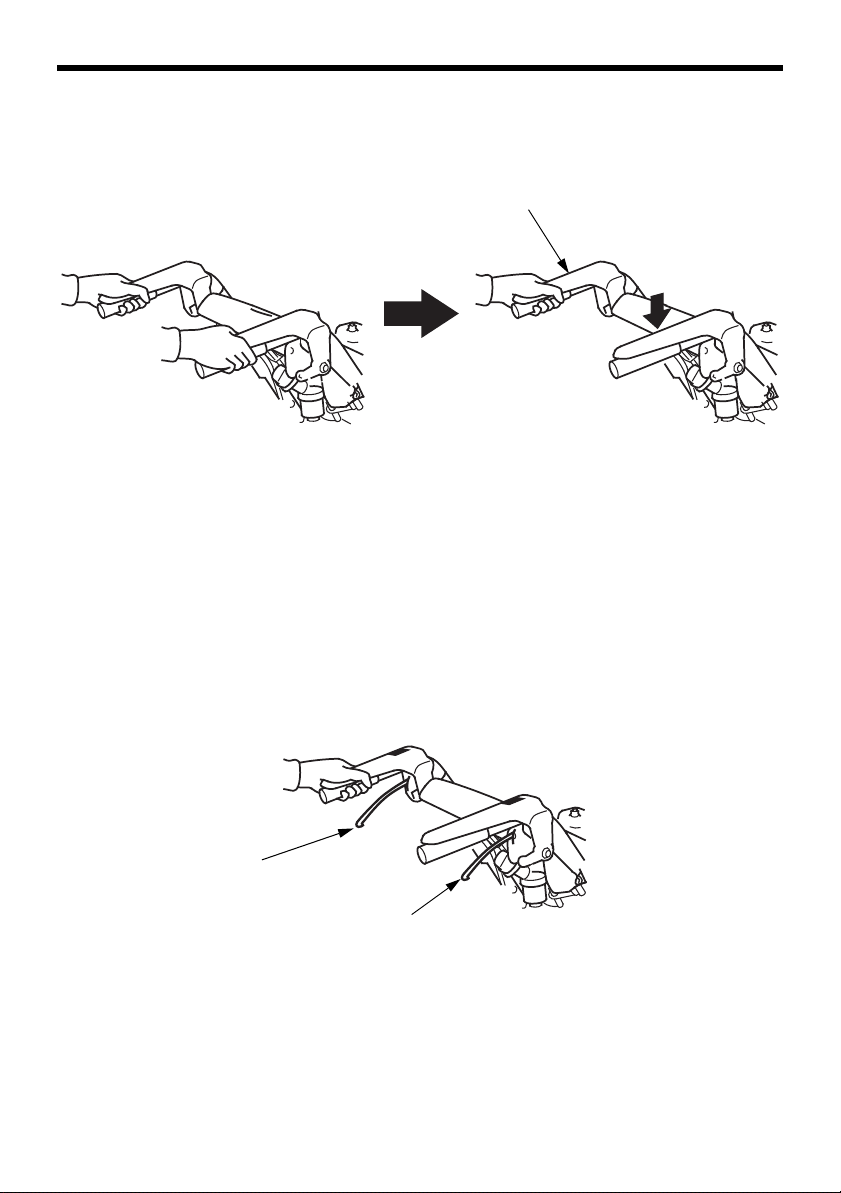
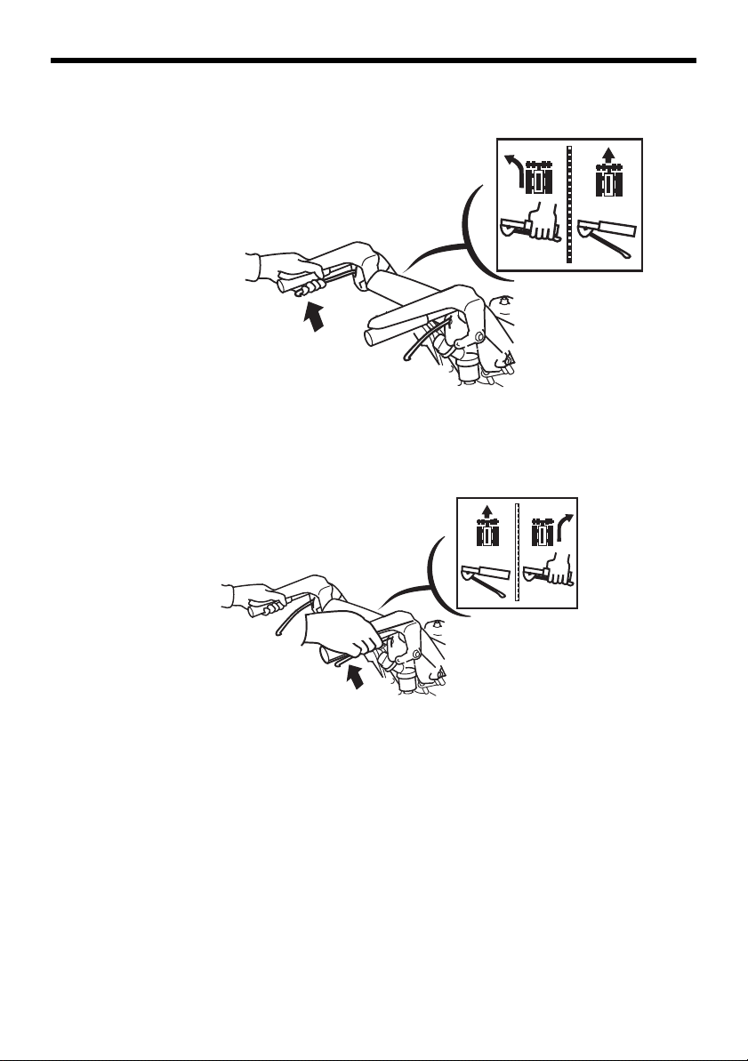
Height adjust lever (AT, ATD)
Use the infinitely variable height adjust lever to change the height of
the auger housing.
1)Hold the handlebar with both hands and depress the lever with your
left thumb.
2)Move the handle up or down as needed to obtain the desired auger
height position.
3)Release the lever to lock the height of the auger in position.
(1) LOWER: Hard snow or fine finish
(2) MIDDLE: Normal use
(3) HIGHER: Deep snow or for transporting the snow thrower.
Do not pull on the gas assisted damper or tie it with a rope, or it may
cause functional damage of the assembly.
21
Page 23
CONTROLS & FEATURES
LED WORK LIGHT
SNOW CLEARING BAR
FEATURES
LED Work Light
The light comes ON while the
engine is running, and it goes OFF
when the engine stops. The light
does not come ON when the
engine switch is turned ON unless
the engine is started.
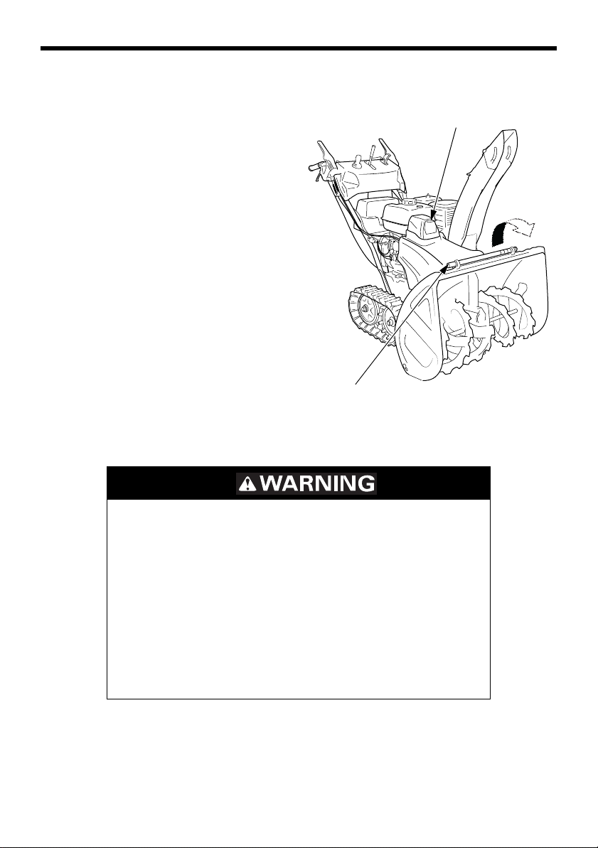
Snow Clearing Bar
If the snow discharge chute or
snow blowing mechanism
becomes restricted, stop the
engine, and make sure all rotating
parts have come to a complete
stop. Remove the spark plug cap
from the spark plug.
Use the snow clearing bar to remove the obstruction.
An obstructed auger or blower could suddenly
move when the obstruction is cleared.
Sudden auger or blower movement will cause
severe injury if your hands are being used to
clear the area.
Never clear the discharge chute or auger area
with your hands, and always stop the engine,
remove the spark plug cap, and clear
obstructions with the clearing bar.
After clearing the obstruction, wipe the bar clean, and store it in the
holders. Replace the spark plug cap.
22
Page 24
BEFORE OPERATION
ARE YOU READY TO GET STARTED?
Your safety is your responsibility. A little time spent in preparation will
significantly reduce the risk of injury.
Knowledge
Read and understand this manual. Know what the controls do and how
to operate them.
Familiarize yourself with the snow blower and its operation before you
begin using it. Know how to quickly shut off the snow blower in case
of an emergency.
IS YOUR SNOW BLOWER READY TO GO?
For your safety, and to maximize the service life of your equipment, it
is very important to take a few moments before you operate the snow
blower to check its condition. Be sure to take care of any problem you
find, or have your servicing dealer correct it, before you operate the
snow blower.
Improperly maintaining this snow blower, or
failing to correct a problem before operation,
could cause a significant malfunction.
Some malfunctions can seriously hurt or kill you.
Always perform a pre-operation inspection
before each operation, and correct any problem.
Before beginning your pre-operation checks, be sure the snow blower
is on a level surface and the engine switch is in the OFF position.
23
Page 25

BEFORE OPERATION
Check the General Condition of the Snow blower:
• Before each use, look around and underneath the snow blower for
signs of oil or gasoline leaks.
• Check the auger housing and the discharge chute for accumulation of
packed snow or ice. Clean the auger housing and discharge chute
before starting the snow blower.
• Look for signs of damage.
• Check each control for proper operation.
• Check the auger and blower for loose or broken bolts. If broken,
replace them with new ones.
• Check the skid shoes and scraper for wear. Replace them if necessary (see page 52).
• Check that all nuts, bolts, and screws are tightened.
Check the Engine
• Check the oil level (see page 44).
• Check the fuel level (see page 42). Starting with a full tank will help
to eliminate or reduce operating interruptions for refueling.
24
Page 26

BEFORE OPERATION
CHECK YOUR WORK AREA
For your safety and the safety of others, always inspect the area
before operating the snow blower.
Objects
Anything that can be picked up by the augers and thrown is a potential
hazard to you and others. Thoroughly inspect the area where the
equipment is to be used and remove all doormats, newspapers, sleds,
boards, wires, stones, and nails from the work area.
People and Pets
People and animals near the work area can move into your snow
blower’s path or into a position where they could be struck by thrown
objects. Clear the area of people, especially children, and pets. Their
safety is your responsibility.
Work Area
Check the condition of the snow. Adjust your snow blower ground
speed (not engine speed) and snow blowing swath accordingly.
Check the skid shoes for proper adjustment. Adjust the skid shoes to
obtain the auger ground clearance for the type of surface the snow
blower will be operated over (see page
52).
25
Page 27

OPERATION
SNOW BLOWING PRECAUTIONS
Before operating the snow blower for the first time, please review both
the SNOW BLOWER SAFETY chapter (see page
OPERATION chapter (see page 23).
Even if you have operated other snow blowers, take time to become
familiar with how this snow blower works, and practice in a safe area
until you build up your skills.
Never tamper with or alter any of the controls or safety devices on the
snow blower. Tampering is a violation of Federal and California law.
For your safety, do not start or operate the engine in an enclosed area
such as a garage. Your snow blower’s exhaust contains poisonous
carbon monoxide gas that can collect rapidly in an enclosed area and
cause illness or death.
Exhaust contains poisonous carbon monoxide
gas that can build up to dangerous levels in
closed areas.
5) and the BEFORE
26
Breathing carbon monoxide can cause
unconsciousness or death.
Never run the engine in a closed, or even partly
closed area where people may be present.
Page 28

STARTING THE ENGINE
SHIFT LEVER
N (Neutral)
DRAIN KNOB
ON
FUEL VALVE LEVER
THROTTLE LEVER
CHOKE
1.Move the shift lever to ‘‘N’’
(Neutral) position.
2.Be sure that the drain knob is
tightened securely. Turn the
fuel valve to the ON position.
OPERATION
3.In cold weather or when the engine is cold, follow the procedures
below.
Move the throttle lever to the CHOKE position.
4.Start the engine.
27
Page 29

OPERATION
DC ELECTRIC ENGINE SWITCH
ONOFF
START
STARTER GRIP
Direction to pull
Electric-start Models (ATD, AWD type):
a. Turn the engine switch to the
START position and release
the switch after the engine
has started. The switch auto
matically returns to the ON
position.
Do not operate the starter for
more than 1 minute. If the
engine fails to start, release
the button and allow the
starter to cool for 15 minutes
before operating it again.
Manual Starting only
a. Turn the engine switch to the
ON position.
b. Pull the starter grip lightly
until you feel resistance, then
pull briskly in the direction of
the arrow as shown.
c. Return the starter grip gently
to the engine.
-
• Do not allow the starter grip to snap back against the engine.
Return it gently to prevent damage to the starter.
• Do not pull the starter grip while the engine is running. The starter
could be damaged.
28
Page 30

OPERATION
THROTTLE LEVER
SLOW
FAST
NEUTRAL
5.Let the engine warm up for several minutes.
If the choke has been used, move the throttle lever to the SLOW
position as the engine warms up.
6.While warming the engine up, also warm the transmission as follows:
a. Check that the shift lever is in the ‘‘N’’ (Neutral) position.
29
Page 31

OPERATION
ENGAGE
DISENGAGE
DRIVE
CLUTCH
DRIVE CLUTCH LEVER
OFF
ENGINE SWITCH
b. Squeeze the drive
clutch lever for about
30 seconds to warm
up the transmission
fluid.
STOPPING THE ENGINE
To stop the engine in an
emergency, simply turn the engine
switch to the OFF position.
Under normal conditions, use the
following procedure.
30
Page 32

OPERATION
DRIVE CLUTCH LEVER
AUGER CLUTCH LEVER
SHIFT LEVER
N (Neutral)
THROTTLE LEVER
SLOW
FAST
1.Release the auger and drive clutch levers. The drive and snow blowing mechanism will stop operation.
2.Move the shift lever to ‘‘N’’ (Neutral) position.
3.Move the throttle lever to the SLOW
position.
31
Page 33

OPERATION
ENGINE SWITCH
OFF
OFF
ON
FUEL VALVE LEVER
4.Turn the engine switch to the OFF position.
5.Turn the fuel valve to the OFF position.
32
Page 34

CLEARING SNOW
FAST
SHIFT LEVER
FAST
R (Reverse)
SLOW
SLOW
FAST
N (Neutral)
F (Forward)
AUGER CLUTCH LEVER
1.Move the throttle lever to the FAST
position for normal operation.
2.Release the auger clutch lever,
and move the shift lever to
select the desired drive speed.
Faster speed is recommended
for removing heavy or wet
snow.
Slower speed is recommended
for removing deep or hardpacked snow.
OPERATION
3.Set the auger height to the
desired position (see page
21, AT, ATD).
4.Adjust the throwing direction by using the chute joystick control (see
page 17).
5.Depress the auger clutch
lever. The auger will
rotate and the machine
will clear snow when you
depress the auger clutch
lever.
33
Page 35

OPERATION
DRIVE CLUTCH LEVER
DRIVE CLUTCH LEVER
AUGER CLUTCH LEVER
6.Depress the drive clutch lever to self-propel the snow blower.
If the transmission
shift lever (see page
33) is in the
FORWARD (F)
position, the
hydrostatic drive will
propel the snow
blower forward
when you squeeze
the drive clutch
lever.
When both levers
are depressed, the drive clutch lever locks the auger clutch lever
down. This frees your right hand to operate the other snow blower
controls. Releasing the drive clutch lever unlocks and releases the
auger clutch lever.
To move from one place to another, or to change direction, use the
drive clutch lever only. Release both the drive clutch lever and auger
clutch lever, and then depress the drive clutch lever.
7.Release both clutch levers to stop clearing and moving.
34
Page 36

OPERATION
1st
2nd
3rd
SNOW-CLEARING TIPS
For best efficiency, clear snow before it melts, refreezes and hardens.
Do not reduce engine speed while clearing snow.
Operating tips for clearing hard or deep snow:
• Reduce forward speed. If that is not sufficient, use the shift lever to
clear snow with a back and forth motion.
• Clear a narrower swath. Make several passes with the auger overlapping the cleared areas.
• If the snow is deeper than the height of the auger, remove it in several steps, as shown below, or install the drift-breaker kit (optional
part) that is available from authorized Honda snow blower dealers.
35
Page 37

OPERATION
SNOW CLEARING BAR
HOLDERS
REMOVING OBSTRUCTIONS
If the snow discharge chute or snow blowing mechanism becomes
restricted, review snow clearing tips (see page
possibility of reoccurring obstructions.
1.Before removing the obstruction,
be sure to stop the engine, and
make sure that all rotating parts
have come to a complete stop.
Remove the spark plug cap from
the spark plug.
2.Remove the snow clearing bar,
or use a wooden stick to clear
the obstruction.
An obstructed auger or blower could suddenly
move when the obstruction is cleared.
35) to reduce the
Sudden auger or blower movement will cause
severe injury if your hands are being used to
clear the area.
Never clear the discharge chute or auger area
with your hands, and always stop the engine,
remove the spark plug cap, and clear
obstructions with the clearing bar.
3.After unclogging, wipe the bar clean, and secure it in the holders.
4.Reinstall the spark plug cap on the spark plug.
36
Page 38

SERVICING YOUR SNOW BLOWER
THE IMPORTANCE OF MAINTENANCE
Good maintenance is essential for safe, economical, and trouble-free
operation. It will also help reduce air pollution.
To help you properly care for your snow blower, the following pages
include a maintenance schedule, routine inspection procedures, and
simple maintenance procedures using basic hand tools. Other service
tasks that are more difficult, or require special tools, are best handled
by professionals and are normally performed by a Honda technician or
other qualified mechanic.
The maintenance schedule applies to normal operating conditions. If
you operate your snow blower under unusual conditions, consult your
servicing dealer for recommendations applicable to your individual
needs and use.
Remember that your authorized Honda servicing dealer knows your
snow blower best and is fully equipped to maintain and repair it.
Improper maintenance, or failure to correct a
problem before operation, can cause a malfunction.
Some malfunctions can seriously hurt or kill you.
Always follow the inspection and maintenance
recommendations and schedules in this owner’s
manual.
To ensure the best quality and reliability, use only new, Honda Genuine
parts or their equivalents for repair or replacement.
Maintenance, replacement, or repair of the emission control devices
and systems may be performed by any engine repair establishment or
individual, using parts that are “certified” to EPA standards.
37
Page 39

SERVICING YOUR SNOW BLOWER
MAINTENANCE SAFETY
Some of the most important safety precautions follow. However, we
cannot warn you of every conceivable hazard that can arise in
performing maintenance. Only you can decide whether or not you
should perform a given task.
Improper maintenance can cause an unsafe
condition.
Failure to properly follow maintenance
instructions and precautions can cause you
to be seriously hurt or killed.
Always follow the procedures and
precautions in this manual.
Safety Precautions
• Make sure the engine is off before you begin any maintenance or
repairs. This will eliminate several potential hazards:
– Carbon monoxide poisoning from engine exhaust.
Operate outside, away from open windows or doors.
– Burns from hot parts.
Let the engine and exhaust system cool before touching.
– Injury from moving parts.
Do not run the engine unless instructed to do so.
• Read the instructions before you begin, and make sure you have the
tools and skills required.
• To reduce the possibility of fire or explosion, be careful when working around gasoline. Use only a nonflammable solvent, not gasoline,
to clean parts. Keep cigarettes, sparks, and flames away from all
fuel-related parts.
38
Page 40

SERVICING YOUR SNOW BLOWER
SPARK PLUG WRENCH
WRENCH HANDLE
14×17 mm
WRENCH
10×12 mm
WRENCH
6 mm SELF LOCK
NUTS (6)
SHEAR
BOLTS (4)
TOOL BAG
SHEAR
BOLTS (2)
FUSE 5 A
(ATD, AWD)
TOOL KIT
The tools necessary for performing some of the periodic maintenance,
simple adjustments and repairs are supplied in the tool kit.
Spare shear bolts and nuts are also included in the tool kit.
39
Page 41

SERVICING YOUR SNOW BLOWER
REGULAR SERVICE PERIOD (1)
Perform at every
indicated month or
operating hour interval,
whichever comes first.
Item
MAINTENANCE SCHEDULE
Every year
First
Each
use
operation
Before
storage
month
or
20 hrs.
Every
100
hrs.
Every
300
hrs.
Every
4 years
PageBefore
Engine oil Check level o 44
Auger
transmission oil
Spark plug Check-adjust o (4) 47
Auger skid
shoes and
scraper
Track Check-adjust o (4) o 49
Wheel Check -
Auger and
blower shear
bolts
Bolts, nuts,
fasteners
Fuel sediment
cup
Fuel tank and
carburetor
(1)For professional commercial use, log hours of operation to determine proper maintenance
intervals.
(2)These items should be serviced by your Honda servicing dealer, unless you have the proper
tools and are mechanically proficient. Refer to the Honda Shop Manual for service proce
dures.
See ‘‘Honda Publications’’ on page 75 for ordering information.
(3)Check the belt for wear or damage. Replace the belt with a new one if it is worn or dam-
aged.
(4)These parts may required more frequent inspection and replacement under heavy use.
Change o (4) o o (4) 45
Check level o (2)
Replace o o
Check-adjust o o (4)
condition
and tire pres
sure
Check o
Check o 24
Clean o 57
Drain o 57
o o
-
—
52
58
51
-
Failure to follow this maintenance schedule could result in nonwarrantable failures.
40
Page 42

SERVICING YOUR SNOW BLOWER
REGULAR SERVICE PERIOD (1)
Perform at every
indicated month or
operating hour interval,
whichever comes first.
Item
Every year
First
Every
Each
use
operation
Before
storage
month
or
20 hrs.
100
hrs.
Every
300
hrs.
Every
4 years
PageBefore
Lubrication
points
Drive chains
(track models)
Chute guide
control cable
Auger clutch
cable
Throttle/Choke
cable
Drive clutch
cable
Height adjust
lever
Drive belt Check-adjust
Auger belt Check-adjust
Idle speed Check-adjust o (2) o (2) —
Valve clearance Check-adjust o (2) o (2) —
Combustion
chamber
Fuel tank and
filter
Fuel tube Check Every 2 years (2)
Battery (if
equipped)
(1)For professional commercial use, log hours of operation to determine proper maintenance
intervals.
(2)These items should be serviced by your Honda servicing dealer, unless you have the proper
tools and are mechanically proficient. Refer to the Honda Shop Manual for service proce
dures.
See ‘‘Honda Publications’’ on page 75 for ordering information.
(3)Check the belt for wear or damage. Replace the belt with a new one if it is worn or dam-
aged.
(4)These parts may required more frequent inspection and replacement under heavy use.
Apply
grease/lube
Lubricate o 54
Check-adjust o (2) (4)
Check-adjust o (2) (4)
Check-adjust o (2) (4)
Check-adjust o (2) (4)
Check
movement
Clean After every 1,000 hrs. (2)
Clean o (2) o (2)
Replace o (2)
Check volt-
age
Charge o o
o (2) (4)
o (2) (3) (4)
o (2) (3) (4)
Charge if voltage is less than 12.9 V.
o 54
o (2) (4)
o (2) (4)
o (2) (4)
o(2)(3)(4)
o(2)(3)(4)
—
—
—
—
—
—
—
—
—
58
-
Failure to follow this maintenance schedule could result in nonwarrantable failures.
41
Page 43

SERVICING YOUR SNOW BLOWER
FUEL TANK CAP
FUEL GAUGE
FUEL INLET
FUEL TANK TOP
MAXIMUM
FUEL LEVEL
1.4 inch
(35 mm)
REFUELING
With the engine stopped, remove the fuel tank cap and check the fuel
level. Refill the tank if the fuel level is low. Do not fill above the base of
the filler neck.
Gasoline is highly flammable and explosive.
You can be burned or seriously injured when
handling fuel.
• Keep heat, sparks, and flame away
• Stop the engine and let it cool before refueling
• Refuel only outdoors
• Wipe up spills immediately
Refuel in a well-ventilated area before starting the engine. If the engine
has been running, allow it to cool. Refuel carefully to avoid spilling fuel.
Add fuel only while standing on the fuel tank side of the snow blower.
Do not fill the fuel tank completely. Fill tank to approximately 1.4 inch
(35 mm) below the top of the fuel tank to allow for fuel expansion. It
may be necessary to lower the fuel level depending on operating
conditions. After refueling, tighten the fuel tank cap securely.
42
Page 44

SERVICING YOUR SNOW BLOWER
Never refuel the snow blower inside a building where gasoline fumes
may reach flames or sparks. Keep gasoline away from appliance pilot
lights, barbecues, electric appliances, power tools, etc.
Spilled fuel is not only a fire hazard, it causes environmental damage.
Wipe up spills immediately.
Fuel can damage paint and plastic. Be careful not to spill fuel when
filling your fuel tank. Damage caused by spilled fuel is not covered
under warranty.
FUEL RECOMMENDATIONS
These engines are certified to operate on unleaded gasoline with a
pump octane rating of 86 or higher.
You may use regular unleaded gasoline containing no more than 10%
ethanol (E10) or 5% methanol by volume. In addition, methanol must
contain cosolvents and corrosion inhibitors.
Use of fuels with content of ethanol or methanol greater than shown
above may cause starting and/or performance problems. It may also
damage metal, rubber, and plastic parts of the fuel system.
Engine damage or performance problems that result from using a fuel
with percentages of ethanol or methanol greater than shown above are
not covered under the Distributor’s Limited Warranty.
Never use stale or contaminated gasoline or an oil/gasoline mixture.
Avoid getting dirt or water in the fuel tank.
If your equipment will be used on an infrequent basis, please refer to
the fuel section of the STORAGE chapter (see page
information regarding fuel deterioration.
56) for additional
43
Page 45

SERVICING YOUR SNOW BLOWER
ENGINE OIL LEVEL CHECK
Check the engine oil level with the engine stopped and in a level
position.
1.Remove the oil filler cap.
2.Check the oil level. If it is below the upper limit, fill with the recommended oil to the upper limit (see page 46).
3.Reinstall the oil filler cap securely.
UPPER LIMIT
LOWER LIMIT
OIL FILLER CAP
Running the engine with a low oil level can cause engine damage. This
type of damage is not covered by the Distributor’s Limited Warranty.
44
Page 46

SERVICING YOUR SNOW BLOWER
DRAIN PLUG
SEALING WASHER
ENGINE OIL CHANGE
Drain the oil while the engine is still warm to assure rapid and complete
draining.
1.Place the snow blower on a level surface.
2.Place a suitable container below the engine (right side) to catch the
used oil, then remove the oil filler cap and the drain plug.
To avoid loosening the drain plug extension, hold it with a 17 mm
wrench while loosening the drain plug with a 10 mm wrench.
3.Allow the used oil to drain completely into an approved container,
then reinstall the drain plug with a new sealing washer, and tighten it
securely.
TORQUE: 8.1 ft-lb (11 N•m)
Improper disposal of engine oil can be harmful to the environment.
If you change your own oil, please dispose of used motor oil
properly. Put it in a sealed container, and take it to a recycling
center. Do not throw it in the trash, pour it on the ground, or pour it
down a drain.
45
Page 47

SERVICING YOUR SNOW BLOWER
LOWER LIMIT
OIL FILLER CAP
UPPER LIMIT
AMBIENT TEMPERATURE
4.With the engine in a level position, fill to the upper limit with the recommended oil (shown below).
Maximum oil capacity: 0.6 US qt (0.6 L)
Running the engine with a low oil level can cause engine damage.
This type of damage is not covered by the Distributor’s Limited
Warranty.
5.Reinstall the oil filler cap securely.
ENGINE OIL RECOMMENDATIONS
Oil is a major factor affecting performance and service life. Use a
4-stroke automotive detergent oil.
SAE 5W-30 is recommended for general use.
The SAE oil viscosity and service classification are on the API label on
the oil container. Honda recommends that you use API SERVICE
category SJ or later (or equivalent) oil.
46
Page 48

SERVICING YOUR SNOW BLOWER
SPARK PLUG WRENCH
SPARK PLUG CAP
SPARK PLUG SERVICE
Recommended spark plug:BPR5ES (NGK)
W16EPR-U (DENSO)
Use only the recommended spark plugs or equivalent. Spark plugs
which have an improper heat range may cause engine damage.
To ensure proper engine operation, the spark plug must be properly
gapped and free of deposits. If the engine has been running, the
muffler will be very hot. Be careful not to touch the muffler.
1.Remove the spark plug cap.
2.Clean any dirt from around the
spark plug base.
3.Use the spark plug wrench supplied in the tool kit to remove
the spark plug.
4.Inspect the spark plug. Replace
it if the electrodes are worn or if
the insulator is cracked,
chipped, or fouled.
47
Page 49

SERVICING YOUR SNOW BLOWER
SIDE ELECTRODE
0.028–0.031 in
(0.7–0.8 mm)
SEALING
WASHER
INSULATOR
5.Measure the plug gap with a
wire-type feeler gauge. Correct
as necessary by carefully bend
ing the side electrode.
The gap should be:
0.028–0.031 in (0.7–0.8 mm)
6.Make sure that the spark plug
sealing washer is in good condi
tion, and thread the spark plug in
by hand to prevent
cross-threading.
7.After the spark plug is seated, tighten with a spark plug wrench to
compress the washer.
TORQUE: 13 ft-lb (18 N•m)
If you don’t have a torque wrench, install a new spark plug and
tighten 1/2 turn after the spark plug seats to compress the washer. If
reinstalling a used spark plug, tighten 1/8 to 1/4 turn after the spark
plug seats.
-
-
The spark plug must be securely tightened. An improperly tightened
spark plug can become very hot and may damage the engine.
48
Page 50

SERVICING YOUR SNOW BLOWER
7/16–5/8 in
(11–16 mm)
TRACK
11 lbf (49 N)
TENSION BOLT
LOCK NUT
ADJUSTING NUT
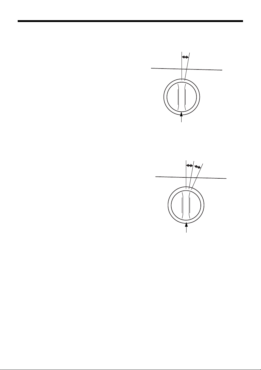
TRACK ADJUSTMENT
Make sure the tracks are clean and dry before adjustment. The tracks
cannot be correctly adjusted if clogged with snow or debris, or coated
with ice.
With the snow blower resting on its tracks, check track deflection by
pressing down midway between the wheels with a force of 11 lbf
(49 N).
When correctly adjusted, track deflection should be:
7/16–5/8 in (11–16 mm)
Adjusting Procedure
1.Loosen the left and right tension
bolt lock nuts at the rear axle,
and turn the adjusting nuts to
correctly tension both tracks.
2.After adjustment, tighten the
lock nuts securely.
TORQUE: 16 ft-lb (21.5 N•m)
49
Page 51

SERVICING YOUR SNOW BLOWER
TIRE INSPECTION
• Check the side wall and tread
surface of each tire for cracks,
damage, or excessive wear.
• Check the tire pressure
Tire pressure:
20 psi (138 kPa)
Excessive inflation pressure can
damage the tires. Do not inflate the tires beyond the recommended
pressure of 23 psi (159 kPa).
AUGER AND BLOWER INSPECTION
Check the auger, auger housing, blower, and shear bolts for signs of
damage or other faults. If any of the shear bolts are broken, replace
them with the ones furnished with the snow blower. Additional shear
bolts and nuts are available from authorized Honda snow blower
dealers.
Shear bolts are designed to break under force that would otherwise
damage auger and blower parts. Do not replace shear bolts with
ordinary hardware bolts.
50
Page 52

SERVICING YOUR SNOW BLOWER
6 mm SELF LOCK NUTS
SHEAR BOLT
SHEAR BOLTS
SHEAR BOLT REPLACEMENT PROCEDURE
Always use correctly sized replacement shear bolts. Use of bolts other
than correctly sized shear bolts can cause damage to your snow
blower.
1.Place the snow blower on a firm, level surface.
2.Turn the engine switch OFF, and remove the cap from the spark
plug.
3.Clean the auger and blower of snow, ice, or any other foreign particles.
4.Check the entire snow clearing mechanism.
5.Replace any broken shear bolts. Tighten securely.
51
Page 53

SERVICING YOUR SNOW BLOWER
SKID SHOES AND SCRAPER
Turn the engine switch to the OFF position, and disconnect the spark
plug cap, so the engine cannot be accidentally started while you are
near the auger.
The skids are installed on the auger housing: rear (track models AT,
ATD) or side (wheel models AW, AWD).
Loosen the bolts to move the skids, and then set the skid to the
convenient position and tighten the bolts securely.
Wheel models (AW, AWD):
For better clearing of hard packed snow, remove the side skid shoes
and install the included rear skid shoes to the auger housing.
Wear inspection
1.Raise the auger housing off the ground.
2.Measure the thickness of the right and left skid shoes at their thinnest point.
If the thickness of the skid contacting the ground surface is 0.02 in
(0.5 mm), turn the skid upside down.
Replace the skid if the thickness is less than 0.02 in (0.5 mm) after
turning the skid upside down.
Adjustment
1.Place the snow blower on a level surface.
2.Track models: Depress the auger height lever, push down on the
handlebars to raise the auger off the ground and then slowly lower
the auger until the skid shoes contact the ground.
3.Loosen the skid shoe bolts and adjust the skid shoes to obtain the
auger ground clearance for snow conditions recommended below.
Adjust the right and left skid shoes equally. Retighten the bolts.
52
Page 54

SERVICING YOUR SNOW BLOWER
AUGER
AUGER:
5/32–5/16 in
(4.0–8.0 mm)
SCRAPER:
3/32–5/32 in
(2.0–4.0 mm)
SKID
(AT, ATD)
SKID
(AW, AWD)
SCRAPER
4.After adjusting, raise the auger off the ground and then slowly lower
and make sure both skid shoes contact the ground at the same time.
Auger clearance:
Ordinary snow conditions 5/32–5/16 in (4.0–8.0 mm)
Smooth, ice-covered surfaces 0–3/16 in (0–5.0 mm)
Rough or uneven surfaces 1–1-3/16 in (25.0–30.0 mm)
Operation on rough or uneven surfaces with less than the
recommended auger ground clearance can damage the snow blower.
5.Check the scraper ground clearance and readjust if necessary.
Retighten the nuts and bolts.
Scraper Ground Clearance 3/32–5/32 in (2.0–4.0 mm)
Adjust the scraper equally on both sides so that it remains parallel with
the ground. Be sure to tighten the scraper bolts after making
adjustments.
TORQUE: 20 ft-lb (26.5 N•m)
53
Page 55

STORAGE
CHUTE GUIDE
LEVERS
SLIDING SURFACE
AUGER WASHERS
SHIFT AND THROTTLE LEVERS
SLIDING SURFACE
WASHER (2)
TRACK DRIVE CHAIN
Hondalube spray
STORAGE PREPARATION
Proper storage preparation is essential for keeping your snow blower
trouble-free and looking good. The following steps will help to keep
rust and corrosion from impairing your snow blower’s function and
appearance, and will make the engine easier to start when you use the
snow blower again.
Cleaning
1.Rinse the auger
housing and wheels
(or tracks) with a
garden hose. Wipe
the rest of the snow
blower with a moist
rag.
2.After the snow
blower has dried,
touch up any dam
aged paint.
-
3.Lubricate the areas
shown in the
graphic before stor
age.
54
-
Page 56

STORAGE
Fuel
Depending on the region where you operate your equipment, fuel
formulations may deteriorate and oxidize rapidly. Fuel deterioration and
oxidation can occur in as little as 30 days and may cause damage to
the carburetor and/or fuel system. Please check with your servicing
dealer for local storage recommendations.
Gasoline will oxidize and deteriorate in storage. Old gasoline will cause
hard starting, and it leaves gum deposits that clog the fuel system. If
the gasoline in your snow blower deteriorates during storage, you may
need to have the carburetor and other fuel system components
serviced or replaced.
The length of time that gasoline can be left in your fuel tank and
carburetor without causing functional problems will vary with such
factors as gasoline blend, your storage temperatures, and whether the
fuel tank is partially or completely filled. The air in a partially filled fuel
tank promotes fuel deterioration. Very warm storage/temperatures
accelerate fuel deterioration. Fuel deterioration problems may occur
within a few months, or even less if the gasoline was not fresh when
you filled the fuel tank.
The Distributor’s Limited Warranty does not cover fuel system damage
or engine performance problems resulting from neglected storage
preparation.
You can extend fuel storage life by adding a fuel stabilizer that is
formulated for that purpose, or you can avoid fuel deterioration
problems by draining the fuel tank and carburetor.
55
Page 57

STORAGE
Adding a Fuel Stabilizer to Extend Fuel Storage Life
When adding a fuel stabilizer, fill the fuel tank with fresh gasoline. If
only partially filled, air in the tank will promote fuel deterioration during
storage. If you keep a container of gasoline for refueling, be sure that it
contains only fresh gasoline.
Add fuel stabilizer following the manufacturer’s instructions.
After adding a fuel stabilizer, run the engine outdoors for 10 minutes to
be sure that treated gasoline has replaced the untreated gasoline in the
carburetor.
Service according to the table below:
STORAGE TIME RECOMMENDED SEVICE PROCEDURE TO
PREVENT HARD STARTING
Less than 1 month Fill with fresh gasoline to prevent moisture
buildup.
1 to 3 months Fill with fresh gasoline and add gasoline stabilizer
according to the manufacturers instructions.
With the fuel valve in the OFF position, start the
engine and let run until the engine stops.
More than 3 months Drain the fuel tank and carburetor (page 57).
56
Page 58

Draining the Fuel Tank and Carburetor
DRAIN KNOB
O-RING
(Replace)
SEDIMENT
CUP
1.Place an approved gasoline container
below the carburetor, and use a fun
-
nel to avoid spilling fuel.
2.Loosen the carburetor drain knob,
then move the fuel valve lever to the
ON position. Drain the carburetor until
the fuel tank is empty.
Gasoline is highly flammable and explosive.
You can be burned or seriously injured when
handling fuel.
• Keep heat, sparks, and flames away.
• Handle fuel only outdoors.
• Wipe up spills immediately.
STORAGE
3.After draining, tighten the drain
knob and turn the fuel valve OFF.
4.Remove the fuel sediment cup.
5.Empty the contents into a suitable
container. Clean the fuel sediment
cup.
6.Reinstall the sediment cup and new
O-ring and tighten securely.
57
Page 59

STORAGE
Engine Oil
1.Change the engine oil (see page 45).
2.Remove the spark plug (see page 47).
3.Pour a teaspoon (5 cc) of clean engine oil into the cylinder.
4.Pull the starter rope slowly several times to distribute the oil.
5.Reinstall the spark plug.
6.Pull the starter grip slowly until you feel resistance, then return the
starter grip gently. This will close the valves so moisture cannot
enter the engine cylinder.
Tires
Check the air pressure (see page 50).
Battery Service (ATD, AWD)
If the snow blower will be stored for an extended period, remove the
battery and store in a cool, dry place.
Recharge the battery every 6 months or if the voltage is less than
12.9 V. Recharge every year before operation and before storage.
58
Page 60

STORAGE
COVER PINS
BATTERY
STRAP
BATTERY COVER
NEGATIVE (–)
CABLE
POSITIVE (+) CABLE
NEGATIVE (–)
TERMINAL
POSITIVE (+)
TERMINAL
Battery Removal/Charging/Installation (ATD, AWD)
A commercially available 12 volt battery charger should be used that
can be adjusted to deliver 2 amps or less. An automatic battery charger
is recommended.
1.Remove the battery cover by first pulling the battery strap from the
bottom hook. Pull the cover upward to unsnap the two cover pins.
2.Remove the negative (–) cable from the battery negative (–) terminal
and then remove the positive (+) cable from the battery positive (+)
terminal.
59
Page 61

STORAGE
3.To remove the battery, remove the battery strap from the bottom
hook.
4.Connect the battery charger positive (+) cable to the battery positive
(+) terminal and then connect the battery charger negative (–) cable
to the battery negative (–) terminal.
5.Charge the battery: 5–10 hours at 1.2 A
6.Install the battery in the reverse order of removal.
7.Install the battery cover by holding the bottom of the grommet and
firmly squeezing the front side of the cover to engage each pin into
the grommets.
8.
This symbol on the battery means that this product must not be
treated as household waste.
NOTE:
An improperly disposed of battery can be harmful to the environment
and human health. Always confirm local regulations for battery
disposal.
Fuse Replacement
60
Page 62

Rotate the fuse holder cover and pull the fuse out. Replace if blown
FUSE HOLDER COVER
HSS724A (AWD, ATD)
FUSE (5 A)
with a fuse of the same type and rating.
61
Page 63

STORAGE
STORAGE PRECAUTIONS
If your snow blower will be stored with gasoline in the fuel tank and
carburetor, it is important to reduce the hazard of gasoline vapor
ignition. Select a well-ventilated storage area away from any appliance
that operates with a flame, such as a furnace, water heater, or clothes
dryer. Also avoid any area with a spark-producing electric motor, or
where power tools are operated.
If possible, avoid storage areas with high humidity, because that
promotes rust and corrosion.
Unless all fuel has been drained from the fuel tank, leave the fuel valve
in the OFF position to reduce the possibility of fuel leakage.
Place the snow blower on a level surface. Tilting can cause fuel or oil
leakage.
With the engine and exhaust system cool, cover the snow blower to
keep out dust. A hot engine and exhaust system can ignite or melt
some materials. Do not use sheet plastic as a dust cover. A nonporous
cover will trap moisture around the engine, promoting rust and
corrosion.
REMOVAL FROM STORAGE
Check your snow blower as described in the BEFORE OPERATION
chapter (see page 23) of this manual.
If the fuel was drained during storage preparation, fill the tank with
fresh gasoline. If you keep a container of gasoline for refueling, be sure
that it contains only fresh gasoline. Gasoline oxidizes and deteriorates
over time, causing hard starting.
If the cylinder was coated with oil during storage preparation, the
engine may smoke briefly at startup. This is normal.
62
Page 64
TRANSPORTING
Model
Type
L
H
BEFORE LOADING
1.Loading the snow blower on a trailer should be performed on a firm,
level surface.
2.Use a loading ramp that is strong enough to support the combined
weight of the snow blower and the operator:
Weight of snow blower: (Operating weight)
HSS724A
AT 243 lbs (110 kg)
ATD 253 lbs (115 kg)
AW 220 lbs (100 kg)
AWD 231 lbs (105 kg)
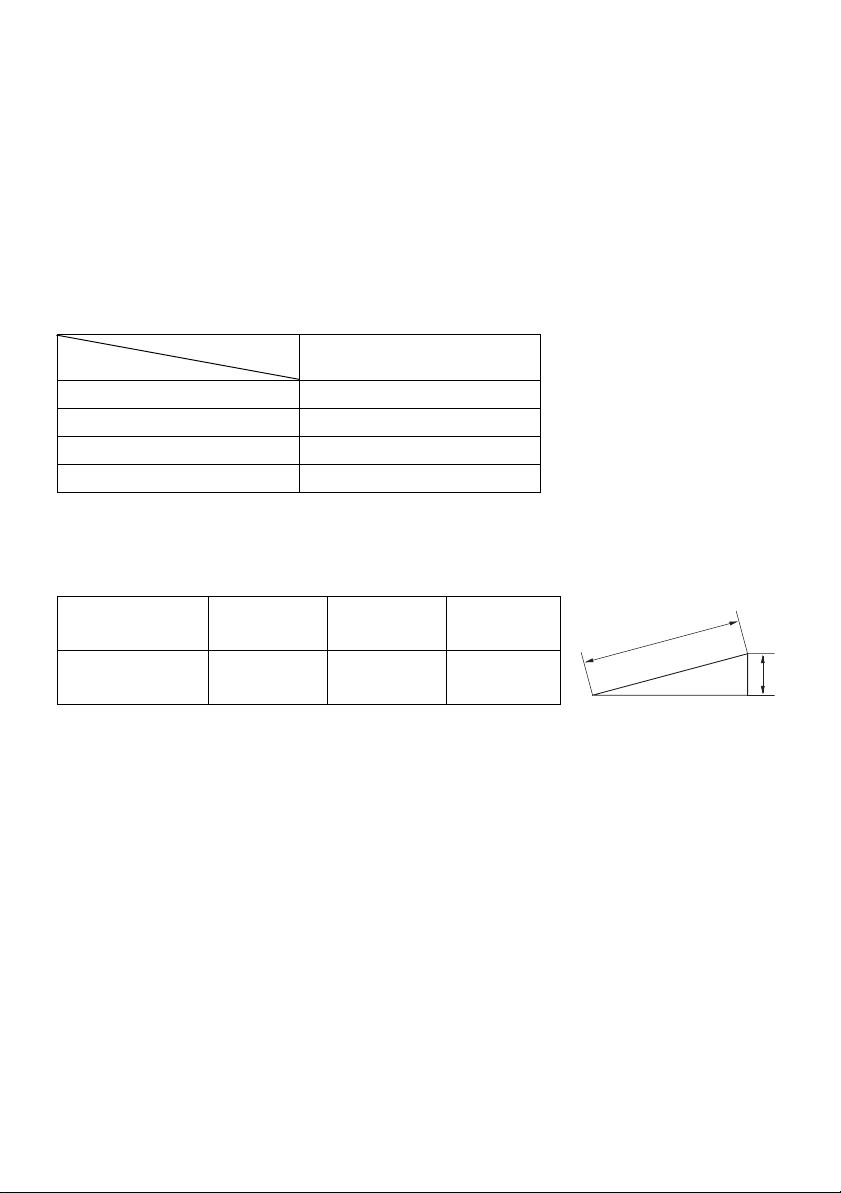
3.The loading ramp must be long enough so that
its slope is 15° (26%) or less.
Length of
Ramp (L)
Height (H) 2.1 ft
4.If the truck bed has a low roof or cover, with less than 5 ft (1.5 m)
of headroom, lower the discharge deflector for better clearance, or
remove the chute assembly.
5.Check that there is sufficient fuel in the tank. The engine may stall
on the ramp if there is not enough fuel in the tank.
8.2 ft
(2.5 m)
(65 cm)
9.8 ft
(3.0 m)
2.5 ft
(75 cm)
11.5 ft
(3.5 m)
3.0 ft
(90 cm)
63
Page 65

TRANSPORTING
DOWN
UP
BACKWARD
L
H
5 ft (1.5 m)
minimum
headroom
LOADING
1.Track type: Raise the auger to the HIGH position (see page 21).
2.Start the engine and maneuver the snow blower backward into line
with the loading ramp.
3.Track type: Run the snow blower backward slowly up the loading
ramp.
Wheel type: Push down the handles to raise the auger and run the
snow blower up the loading ramp.
Be careful to avoid striking the chute or other parts of the machine.
4.After the snow blower is in the truck, stop the engine, and turn the
fuel valve to the OFF position. This will prevent the possibility of
carburetor flooding and will reduce the possibility of fuel leakage.
5.Tie the snow blower down with rope or straps, and block the treads.
Keep the tie-down rope or straps away from controls and cables.
64
Page 66

TRANSPORTING
Front
Rear
Track type:
Wheel type:
Track models: Lower the auger housing so the skids rest on the vehicle
floor.
Do not tie with rope or straps stronger than necessary to prevent
damage to the snow blower.
Tie-down Points
65
Page 67

TAKING CARE OF UNEXPECTED PROBLEMS
ENGINE PROBLEMS
Starter operates, but engine will not start
Possible cause Correction
Throttle not in proper position. Throttle must be in FAST
position, choke OFF for a hot
start, choke ON for a cold start.
Fuel valve is OFF.
Sediment cup obstructed.
Stale or old fuel. Be sure tank has fresh fuel. Drain
Spark plug cap off.
Improper electrode gap or
deposits in the spark plug gap.
Engine has low power
Possible cause Correction
Too fast ground speed when
blowing wet, deep snow puts
excessive load on engine.
Throttle lever not in FAST. Always move the throttle to
Wet, deep cuts place excessive
load on engine.
Discharge chute restricted. Clear discharge chute
Spark plug cap not secure.
Improper electrode gap or
deposits on the electrodes.
Choke in wrong position or
choke plate sticking.
Stale or old fuel. Add fresh fuel. Drain carburetor
Turn fuel valve to ON (see page
15). Check for contaminates in
sediment cup (see page
carburetor and sediment cup (see
57).
page
Make sure cap is connected.
Verify that spark plug is free of
deposits, and has proper gap
(see page 48).
Blow snow at slower ground
speed.
FAST when blowing snow.
Reduce snow blowing swath.
obstructions (see page 22).
Make sure spark plug cap is
securely connected.
Verify the spark plug is free of
deposits and has the proper gap.
Check choke plate movement.
and sediment cup (page
57).
57).
66
Page 68

TAKING CARE OF UNEXPECTED PROBLEMS
DRIVE PROBLEMS
Engine runs, but snow blower doesn’t move
Possible cause Correction
Drive clutch lever is in the
DISENGAGED position.
Shift lever is in ‘‘N’’ (neutral). Move shift lever to “F” or “R”
Drive clutch lever mechanism or
cable not functioning properly.
Drive belt worn, broken or not on
pulleys.
SNOW BLOWER PROBLEMS
Won’t blow snow
Possible cause Correction
Auger clutch lever is the
DISENGAGED position.
Shear bolt(s) broken. Replace broken shear bolt(s)
Discharge chute restricted.
Foreign object stopping auger
from rotating.
Belt worn, not on pulleys or not
properly installed.
Move lever to the ENGAGED
position (see page 18).
(see page 17).
See servicing Honda snow
blower dealer.
See servicing Honda snow
blower dealer.
Move lever to the ENGAGED
position (see page 18).
(see page 51).
Clear discharge chute of
obstructions (see page 22).
Remove foreign object.
See servicing Honda snow
blower dealer.
Snow not discharging properly
Possible cause Correction
Auger spinning too slowly. Keep throttle in FAST position
(see page 16).
Wet, deep snow is difficult to
blow.
Belt worn, not on pulleys or not
properly installed.
Snow blower moving too fast for
snow conditions.
Reduce snow blowing swath or
speed.
See servicing Honda snow
blower dealer.
Use shift lever to reduce ground
speed (see page 17).
67
Page 69

TAKING CARE OF UNEXPECTED PROBLEMS
Engine stalls when auger clutch lever is depressed
Possible cause Correction
Engine running too slow. Keep throttle in FAST position
when engaging auger clutch
(see page 16).
Discharge chute restricted.
Foreign object stopping auger
from rotating.
Auger frozen by ice.
Clear discharge chute or auger
housing of obstruction.
68
Page 70

TECHNICAL INFORMATION
FRAME SERIAL NUMBER
ENGINE SERIAL
NUMBER
Serial Number Locations
Record the engine and frame serial numbers in the spaces below. You
will need these serial numbers when ordering parts, and when making
technical or warranty inquiries (see page 75).
Engine serial number:
Frame serial number:
Date of purchase:
69
Page 71

TECHNICAL INFORMATION
Carburetor Modification for High Altitude Operation
At high altitude, the standard carburetor air-fuel mixture will be too
rich. Performance will decrease, and fuel consumption will increase. A
very rich mixture will also foul the spark plug and cause hard starting.
Operation at an altitude that differs from that at which this engine was
certified, for extended periods of time, may increase emissions.
High altitude performance can be improved by specific modifications to
the carburetor. If you always operate your snow blower at altitudes
above 5,000 feet (1,500 meters) have your servicing dealer perform
this carburetor modification. This engine, when operated at high
altitude with the carburetor modifications for high altitude use, will
meet each emission standard throughout its useful life.
Even with carburetor modification, engine horsepower will decrease
about 3.5% for each 1,000-foot (300-meter) increase in altitude. The
effect of altitude on horsepower will be greater than this if no
carburetor modification is made.
When the carburetor has been modified for high altitude operation, the
air-fuel mixture will be too lean for low altitude use. Operation at
altitudes below 5,000 feet (1,500 meters) with a modified carburetor
may cause the engine to overheat and result in serious engine damage.
For use at low altitudes, have your servicing dealer return the
carburetor to original factory specifications.
70
Page 72

TECHNICAL INFORMATION
Emission Control System Information
Source of Emissions
The combustion process produces carbon monoxide, oxides of
nitrogen, and hydrocarbons. Control of hydrocarbons and oxides of
nitrogen is very important because, under certain conditions, they react
to form photochemical smog when subjected to sunlight. Carbon
monoxide does not react in the same way, but it is toxic.
Honda utilizes appropriate air/fuel ratios and other emissions control
systems to reduce the emissions of carbon monoxide, oxides of
nitrogen and hydrocarbons.
The U.S., California Clean Air Acts, and Environment Canada
EPA, California, and Canadian regulations require all manufacturers to
furnish written instructions describing the operation and maintenance
of emission control systems.
The following instructions and procedures must be followed in order to
keep the Honda engine emissions within the emission standards.
Tampering and Altering
Tampering is a violation of Federal and California law.
Tampering with or altering the emission control system may increase
emissions beyond the legal limit. Among those acts that constitute
tampering are:
• Removal or alteration of any part of intake, fuel or exhaust system.
• Altering or defeating the governor linkage or speed-adjusting mechanism to cause the engine to operate outside its design parameters.
71
Page 73

TECHNICAL INFORMATION
Problems That May Affect Emissions
If you are aware of any of the following symptoms, have your engine
inspected and repaired by your authorized Honda servicing dealer.
• Hard starting or stalling after starting.
• Rough idle.
• Misfiring or backfiring under load.
• Afterburning (backfiring).
• Black exhaust smoke or high fuel consumption.
Replacement parts
The emission control systems on your new Honda engine were
designed, built, and certified to conform with EPA and California
emission regulations. We recommend the use of Honda Genuine parts
whenever you have maintenance done. These original-design
replacement parts are manufactured to the same standards as the
original parts, so you can be confident of their performance. The use of
replacement parts that are not of the original design and quality may
impair the effectiveness of your emission control system.
A manufacturer of an aftermarket part assumes the responsibility that
the part will not adversely affect emission performance. The
manufacturer or rebuilder of the part must certify that use of the part
will not result in a failure of the engine to comply with emission
regulations.
Maintenance
Follow the Maintenance Schedule on pages 40 and 41. Remember that
this schedule is based on the assumption that your machine will be
used for its designed purpose. Sustained high-load operation will
require more frequent service.
72
Page 74

TECHNICAL INFORMATION
Air Index
An Air Index Information hang tag/label is applied to engines certified
to an emission durability time period in accordance with the
requirements of the California Air Resources Board.
The bar graph is intended to provide you, our customer, the ability to
compare the emissions performance of available engines. The lower the
Air Index, the less pollution.
The durability description is intended to provide you with information
relating to the engine’s emission durability period. The descriptive term
indicates the useful-life period for the engine’s emission control
system. See your Emission Control Warranty for additional information.
Descriptive Term Applicable to Emission Durability Period
Moderate 50 hours (0 – 80 cc, inclusive)
125 hours (greater than 80 cc)
Intermediate 125 hours (0 – 80 cc, inclusive)
250 hours (greater than 80 cc)
Extended 300 hours (0 – 80 cc, inclusive)
500 hours (greater than 80 cc)
1,000 hours (225 cc and greater)
73
Page 75

Specifications
Frame
TECHNICAL INFORMATION
Model
Type AT
Items
Description code
Overall length
Overall width
Overall height
Handlebar height
Dry mass [weight]
Width of snow clearance
Height of snow clearance
Snow throwing distance
(varies with snow conditions)
Clearing capacity
HSS724A
ATD
AW
AWD
SABA
58.5 in (1,485 mm)
24.8 in (630 mm) 26.3 (670 mm)
43.5 in (1,105 mm)
37.0 in (940 mm) 36.6 in (930 mm)
231 lbs
(105 kg)
242 lbs
(110 kg)
209 lbs
(95kg)
220 lbs
(100kg)
23.8 in (605 mm)
21.6 in (550 mm)
Max. 49.2 ft (15 m)
42 metric (46 short) Ton/hour
Engine
Model Honda GX200T2
Displacement
Bore×stroke 2.68×2.13 in (68.0×54.0 mm)
Starting method Recoil starter
Ignition system Transistor magneto
Oil capacity 0.6 US qt/20 oz (0.6 L)
Fuel tank capacity 0.82 US gal (3.1 L)
Spark plug BPR5ES (NGK)
12.0 cu-in (196 cm3)
W16EPR-U (DENSO)
Tune-up
ITEM SPECIFICATION MAINTENANCE
Spark plug gap
Valve clearance IN: 0.15±0.02 mm
Other specifications No other adjustments needed.
0.028–0.031 in
(0.7–0.8 mm)
EX: 0.20±0.02 mm
Refer to page: 48
See your authorized
Honda dealer
Specifications are subject to change without notice.
74
Page 76

CONSUMER INFORMATION
Dealer Locator Information
To find an authorized Honda Servicing Dealer anywhere in the United
States. Visit our web site:
powerequipment.honda.com and click on Dealer Locator.
Honda Publications
Shop Manual
This manual covers complete maintenance and overhaul procedures.
It is intended to be used by a skilled technician.
Visit: powerequipment.honda.com/support/shop-manuals
Parts Catalog
This manual provides complete, illustrated parts lists. Available through
your Honda dealer.
Accessories Catalog
Your authorized Honda power equipment dealer offers a selection of
accessories (optional equipment) to make your snow blower even more
useful.
Visit: powerequipment.honda.com/snowblowers/accessories
and click on Snow blowers to see the entire catalog of accessories.
75
Page 77

CONSUMER INFORMATION
Customer Service Information
Honda Power Equipment dealership personnel are highly trained
professionals. They should be able to answer any question you may
have. If you encounter a problem that your dealer does not solve to
your satisfaction, please discuss it with the dealership’s management.
The Service Manager or General Manager can help. Almost all problems
are solved in this way.
If you are dissatisfied with the decision made by the dealership’s
management, contact the Honda Power Equipment Customer Relations
Office. You can write:
American Honda Motor Co., Inc.
Power Equipment Division
Customer Relations Office
4900 Marconi Drive
Alpharetta, Georgia 30005-8847
Or telephone: (770) 497-6400 M-F, 8:30 am to 7:00 pm ET
When you write or call, please give us this information:
• Model and serial number (see page 69)
• Name of the dealer who sold the snow blower to you
• Name and address of the dealer who services your snow blower
• Date of purchase
• Your name, address, and telephone number
• A detailed description of the problem
CONSUMER INFORMATION
76
Page 78

REPLACEMENT PARTS, OPTIONAL EQUIPMENT, AND
SERVICE ITEMS
Contact an authorized Honda servicing dealer to purchase any of these (or other) Honda
Genuine items for your snow blower.
Replacement Parts
Item Part Number Notes
Spark plug 98079-55846 NGK - BPR5ES
Shear bolt 90121-V45-A00
90119-V45-A00
Fuse 98200-40500 5 Amp
Optional Equipment
Item Part Number Notes
Cover Custom fitted, waterproof, and
Blower 6 x 18
Auger 6 x 18
breathable
NO-SPILL® gas can
Battery Tender® Plus
Drift Breaker Kit 06760-768-000AH
No-Spill® is a registered trademark of NoSpill LLC.
See your local dealer. 1-1/4 gallon
2-1/2 gallon
31670-HPE-000 Battery Charger
Service Items
Item Part Number Notes
SAE 5W-30 engine oil 08207-5W30 Honda Genuine recommended oil
Fuel stabilizer (500 ml) 08732-0800 For long term storage
Hondalube 08732-RP001 Track drive model chain only
Touch Up Paint 08707-R280 Honda Red
77
Page 79

DISTRIBUTOR’S LIMITED WARRANTY
Honda Power Equipment
This warranty is limited to the following Honda Power Equipment products when distributed by American Honda Motor Co., Inc., Power Equipment Division, 4900 Marconi
Drive, Alpharetta, Georgia 30005. The following warranty applies to products purchased at retail or placed in rental service on or after January 1, 2010.
Product Covered by this
Snow Blower 36 months 36 months
Warranty
(from date of original retail purchase)
Private Residential Commercial/Rental/
Length of Warranty
Institutional
To Qualify for This Warranty:
The product must be purchased in the United States, Puerto Rico, or the U.S. Virgin
Islands from American Honda or a dealer authorized by American Honda to sell those
products. This warranty applies to first retail purchaser and each subsequent owner
during the applicable warranty time period, unless noted otherwise.
What American Honda Will Repair or Replace Under Warranty:
American Honda will repair or replace, at its option, any part that is proven to be defective in material or workmanship under normal use during the applicable warranty time
period. Warranty repairs and replacements will be made without charge for parts or
labor. Anything replaced under warranty becomes the property of American Honda
Motor Company, Inc. All parts replaced under warranty will be considered as part of
the original product, and any warranty on those parts will expire coincident with the
original product warranty.
To Obtain Warranty Service:
You must, at your expense, take the Honda Power Equipment product, accessory,
replacement part, apparel, or the power equipment on which the accessory or
replacement part is installed, and proof of purchase to any Honda Power
Equipment dealer in the United States, Puerto Rico, or the U.S. Virgin Islands who
is authorized to sell and/or service that product, during the dealer’s normal
business hours. To locate a dealer near you, visit our web site at http://
PowerEquipment.Honda.com and click on Find a Dealer.
If you are unable to obtain warranty service or are dissatisfied with the warranty service you receive,
contact the owner of the dealership involved; normally this will resolve the problem. However, if you
should require further assistance, write or call the Power Equipment Customer Relations Department
of American Honda Motor Co., Inc. at the address on page 74.
78
Page 80

Exclusions:
1. Any damage or deterioration resulting from the following:
- Neglect of the periodic maintenance as specified in the product owner’s manual
- Improper repair or maintenance
- Operating methods other than those indicated in the product owner’s manual
- The use of non-genuine Honda parts, accessories, lubricants, and fluids other than those
approved by Honda
- Exposure of the product to soot and smoke, chemical agents, bird droppings, sea water, sea
breeze, salt, or other environmental phenomena
- Collision, fuel contamination or deterioration, neglect, unauthorized alteration, misuse, incor-
poration or use of unsuitable attachments or parts
- Normal wear and tear (including, but not limit ed to, nor mal f ading of painted or plated surfaces, sheet peeling, and other natural deterioration)
2.Consumable parts: Honda does not warrant parts deterioration due to normal wear and tear. The following parts are not covered by this warranty unless they are needed during an other repair covered
under this warranty: spark plug, fuel filter, air cleaner element, clutch disc, tire, wheel bearing,
recoil starter rope, cable, belt, cutter blade, oil, and grease.
3.Cleaning, adjustment, and normal periodic maintenance work (carburetor cleaning, engine oil
draining, blade sharpening, belt and cable adjustments).
4.Any product that has ever been declared a total loss or sold for salvage by a financial institution or
insurer.
5.Auger and paddle assemblies of snow throwers, tiller tines of roto-tillers, and mower blades and
mower deck housings are specifically not warranted against impact damage including, but not limited to, abrasive damage.
Disclaimer of Consequential Damage and Limitation of Implied Warranties:
American Honda disclaims any responsibility for loss of time or use of the p roduct,
transportation, commercial loss, or any other incidental or consequential damage.
Any implied warranties are limited to the duration of this written limited warranty.
Some states do not allow limitations on how long an implied warranty lasts and/or
do not allow the exclusion or limitation of incidental or consequential damages,
therefore the above exclusions and limitations may not apply to you. This warra nty
gives you specific legal rights, and you may also have other rights, which vary from
state to state.
79
Page 81

EMISSION CONTROL SYSTEM WARRANTY
Your new Honda Power Equipment engine complies with the U.S. EPA,
Environment Canada, and State of California (models certified for sale
in California only) emission regulations. American Honda Motor Co.,
Inc. provides the emission warranty coverage for engines in the United
States and its territories. Honda Canada Inc. provides the emission
warranty for engines in the 13 provinces and territories of Canada. In
the remainder of this Emission Control System Warranty, American
Honda Motor Company Inc. and Honda Canada Inc. will be referred to
as Honda.
YOUR WARRANTY RIGHTS AND OBLIGATIONS:
CALIFORNIA
The California Air Resources Board and Honda are pleased to explain the emission control system
warranty on your 2015 and later Honda Power Equipment engine. In California, new spark-ignited
small off-road equipment engines must be designed, built, and equipped to meet the state's stringent
anti-smog standards. Specific Honda products that do not meet the California emissions regulations
can be identified by a “Not for sale in California” decal.
Other States, U.S. territories, and Canada
In other areas of the United States and in Canada, your engine must be designed, built, and equipped
to meet the U.S. EPA and Environment Canada emission standards for spark-ignited engines at or
below 19 kilowatts.
All of the United States and Canada
Honda must warrant the emission control system on your power equipment engine for the period of
time listed below, provided there has been no abuse, neglect, or imp roper maintenance of your power
equipment engine. Where a warrantable condition exists, Honda will repair your power equipment
engine at no cost to you including diagnosis, parts, and labor.
Your emission control system may include such parts as the carburetor or fuel injection system, the
ignition system, and catalytic converter. Also included may be ho ses, connectors, and other emissionrelated assemblies (see page 80 for additional covered parts
OWNER'S WARRANTY RESPONSIBILITY
As the power equipment engine owner, you are responsible for completing all required maintenance
listed in your owner's manual. Honda recommends that you retain all receipts covering maintenance
on your power equipment engine, but Honda cannot deny warranty coverage solely for the lack of
receipts or for your failure to ensure that all scheduled maintenance has been completed.
As the power equipment engine owner, you sh ould however be aware Honda may deny you warranty
coverage if your power equipment engine or a part has failed due to abuse, neglect, improper
maintenance, or unapproved modifications.
Y ou are responsible for presenting your power equipment engine to a Honda Power Equipment dealer
as soon as a problem exists. The emission related warranty repairs should be completed in a reasonable
amount of time, not to exceed 30 days.
If you have any questions regarding your emission warranty rights and responsibilities, you should
.
80
Page 82

contact the Honda office in your region:
American Honda Motor Co., Inc.
Power Equipment Customer
Relations
4900 Marconi Drive
Alpharetta, Georgia 30005-8847
Telephone: (888) 888-3139
Email:
powerequipmentemissions@ahm.ho
nda.com
or
Honda Canada Inc.
Power Equipment Customer
Relations
180 Honda Blvd.
Markham, ON, L6C 0H9
Telephone: (888) 946-6329
81
Page 83

WARRANTY COVERAGE
Honda power equipment engines sold in the United States and Canada are covered by this warranty
for a period of two years from the date of delivery to the original retail purchaser o r the length of the
Honda Distributor’s Limited Warranty, whichever is longer. This warranty is transferable to each
subsequent purchaser for the duration of the warranty period.
If any emission-related part on your engine is defective, the part will be repaired or replaced by Honda
without charge for diagnosis, parts, or labor . All defective parts replaced under this warranty become
the property of Honda. Only Honda approved replacement parts may be used in the performance of
any warranty repairs and must be provided without charge to the owner . A list of warranted parts is on
the reverse side of this warranty statement. Normal maintenance items, such as spark plugs and filters,
that are on the warranted parts list are warranted up to their required replacement interval only.
Honda will also replace other engine components damaged by a failure of any warranted part during
the warranty period.
The use of replacement parts not equivalent to the original parts may impair the effectiveness of your
engine emission control system. If such a replacement part is used in the repair or maintenance of your
engine, and an authorized Honda dealer determines it is defective or causes a failure of a warranted
part, your claim for repair of your engine may be denied. If the part in question is not related to the
reason your engine requires repair, your claim will not be denied.
TO OBTAIN WARRANTY SERVICE
Y ou must, at your own expense, take y our Honda Power Equipment engine or the product on which it
is installed, along with your sales registration card or other proof of original purchase date, to any
Honda Power Equipment dealer who is authorized by Honda to sell and service that Honda product
during their normal business hours. Claims for repair or adjustment found to be caused solely by
defects in material or workmanship will not be denied because the engine was not properly maintained
and used.
If you are unable to obtain emission warranty service or are dissatisfied with the warranty service you
received, contact the owner of the dealership involved. Normally this should resolve your problem.
However, if you require further assistance, contact the Honda office in your region:
American Honda Motor Co., Inc.
Power Equipment Customer Relations
4900 Marconi Drive
Alpharetta, Georgia 30005-8847
Telephone: (888) 888-3139
Email:
powerequipmentemissions@ahm.honda.co
Honda Canada Inc.
Power Equipment
Customer Relations
180 Honda Blvd.
o
Markham, ON, L6C 0H9
r
Telephone: (888) 9466329
m
EXCLUSIONS
Failures other than those resulting from defects in material or workmanship are not covered by this
warranty. This warranty does not extend to emission control systems or parts that are affected or
damaged by owner abuse, neglect, improper maintenance, misuse, misfueling, improper storage,
collision, the incorporation of, or use of, unsuitable attachments, or the unauthorized alteration of any
part.
This warranty does not cover replacement of expendable maintenance items made in connection with
required maintenance service after the item’s first scheduled replacement as listed in the maintenance
section of the product owner’s manual, such as: spark plugs and filters.
82
Page 84

DISCLAIMER OF CONSEQUENTIAL DAMAGE AND LIMITATION OF IMPLIED
WARRANTIES
American Honda Motor Co., Inc. and Honda Canada Inc. disclaim any responsibility for incidental or
consequential damages such as loss of time or the use of the power equipment, or any commercial loss
due to the failure of the equipment; and any implied warranties are limited to the duration of this
written warranty. This warranty is applicable only where the California, U.S. EPA, or Environment
Canada emission control system warranty regulation is in effect.
EMISSION CONTROL SYSTEM WARRANTY PARTS
SYSTEMS COVERED
BY THIS WARRANTY:
Carburetor assembly (includes starting enrichment system), Oxygen
Fuel Metering
Evaporative Fuel tank, Fuel cap, Fuel hoses, Vapor hoses, Carbon canister, Canister
Exhaust Catalyst, Exhaust pipe, Muffler (with cat alyst)
Air Induction Air cleaner case, Air cleaner element*
Ignition
Crankcase Emission
Control
Miscellaneous Parts Tubing, fittings, seals, gaskets, and clamps
Note: This list applies to parts supplied by Honda and does not cover parts supplied by the
equipment manufacturer. Please see the original equipment manufacturer’s emissions warranty for
non-Honda parts.
* Covered up to the first required replacement only. Se e the Maintenance Schedule in this manual.
sensor, Throttle body, Engine temperature sensor, Engine control
module, Fuel injector, Fuel regulator, Intake manifold
mounting brackets, Fuel strainer, Fuel valve, Fuel pump, Fuel hose
joint, Canister purge hose joint
Flywheel comp., Flywheel magneto, Ignition pulse generator,
Crankshaft position sensor, Power coil, Igni tion coil assem bly, Ignition
control module, Spark plug cap, Spark plug*
Crankcase breather tube, Breather valve assembly, Oil filler cap
associated with these listed systems
PARTS
DESCRIPTION:
83
Page 85

QUICK REFERENCE INFORMATION
Fuel Type Unleaded gasoline with an
ethanol content of no more than
10% and a pump octane rating of
86 or higher
Engine Oil
Spark Plug Type BPR5ES (NGK)
Tires Tire
Maintenance Before each
Type SAE 5W-30 API SJ or later for
general use
Maximum oil capacity:
1.1 US qt (1.1 L)
W16EPR-U (DENSO)
20 psi (138 kPa)
Pressure
Engine oil level.
use, check the
following.
First
20 hours
Subsequent See Maintenance Schedule
Tire air pressure.
Auger skid shoes and scraper.
Auger and blower lock bolt.
Bolt and nut torque.
Change engine oil.
(see page 40)
84
Page 86

© 2015 American Honda Motor Co., Inc.
—All Rights Reserved
Printed on
Recycled Paper
HPE.2015.10
PRINTED IN U.S.A
Page 87

PRODUCT REGISTRATION
(commercial/rental users)
(check one)
(private, homeowner use) (for-hire use)
Owner's Last Name
Company Name
Address
City
Purchased Via
First Name
Telephone
()
State ZIP Code
Application
Commercial
Serial number
(professional use)
* Dealer ZIP code
* Dealer Store number
*If available
E-mail address
Date of Purchase
MONTH YEARDAY
(check one)
In Store Online
Non-commercial Rental
S
A
Print the serial number here.
Thank you for choosing Honda!
Please register your snow blower within 30 days of purchase to ensure you receive
important service information in the event of a product update or recall
and for added coverage during certain sales promotions.
Your information will remain confidential. It will not be released to any other company or organization.
There are three ways to register, select one:
• Complete and mail the postage paid card shown below
• Complete and submit the online form at powerequipment.honda.com
• Scan the QR code below and then complete and submit the online form
Page 88

1. Go to PowerEquipment.Honda.com to register your unit.
2. Click on Product Registration.
3. Complete the required information and click Submit.
It’s that simple!
Power Equipment Division
American Honda Motor Co. Inc.
4900 Marconi Dr
Alpharetta GA 30005-9956
NO POSTAGE
NECESSARY
IF MAILED
IN THE
UNITED STATES
Product Registration
BUSINESS REPLY MAIL
FIRST-CLASS MAIL ALPHARETTA GAPERMIT NO. 117
POSTAGE WILL BE PAID BY ADDRESSEE
00X51V45 A000
HPE.2015.08
PRINTED IN U.S.A.
 Loading...