

Page 1

Owner,s Manual
SNOWBLOWER
HS1336i
C
2011 Honda Motor Co., Ltd. -All Rights Reserved
Page 2

The engine exhaust from this product
contains chemicals known to the State
of California to cause cancer, birth
defects or other reproductive harm.
Keep this owner’s manual handy, so you can refer to it any time. This
owner’s manual is considered a permanent part of the snowblower
and should remain with the snowblower if resold.
The information and specifications included in this publication were in
effect at the time of approval for printing. Honda Motor Co., Ltd.
reserves the right, however, to discontinue or change specifications or
design at any time without notice and without incurring any obligation
whatever.
Page 3

INTRODUCTION
Congratulations on your selection of a Honda snowblower. We are
certain you will be pleased with your purchase of one of the finest
snowblowers on the market.
We want to help you get the best results from your new snowblower
and to operate it safely. This manual contains the information on how
to do that; please read it carefully.
As you read this manual, you will find information preceded by a
symbol. That information is intended to help you avoid
damage to your snowblower, other property, or the environment.
We suggest you read the
understand its coverage and your responsibilities of ownership. The
Distributor’s Limited Warranty
have been given to you by your dealer.
When your snowblower needs scheduled maintenance, keep in mind
that your Honda servicing dealer is specially trained in servicing
Honda snowblowers. Your Honda servicing dealer is dedicated to your
satisfaction and will be pleased to answer your questions and
concerns.
Best Wishes,
Honda Motor Co., Ltd.
Distributor’s Limited Warranty
is a separate document that should
to fully
1
Page 4
INTRODUCTION
A FEW WORDS ABOUT SAFETY
Your safety and the safety of others are very important. And using this
snowblower safely is an important responsibility.
To help you make informed decisions about safety, we have provided
operating procedures and other information on labels and in this
manual. This information alerts you to potential hazards that could
hurt you or others.
Of course, it is not practical or possible to warn you about all the
hazards associated with operating or maintaining a snowblower. You
must use your own good judgment.
You will find important safety information in a variety of forms,
including:
on the snowblower.
Safety Labels
Safety Messages
of three signal words, DANGER, WARNING, or CAUTION.
−
preceded by a safety alert symbol and one
−
These signal words mean:
You WILL KILLED SERIOUSLY HURT
you don’t follow instructions.
You CAN KILLED SERIOUSLY HURT
you don’t follow instructions.
You CAN HURT
instructions.
such as
Safety Headings
Safety Section
Instructions
This entire book is filled with important safety information please
read it carefully.
−
−
such as
−
how to use this snowblower correctly and safely.
be or if
be or if
be if you don’t follow
IMPORTANT SAFETY INFORMATION
SNOWBLOWER SAFETY
.
−
2
.
Page 5

CONTENTS
............................................................................................CONTROLS .14
......................................................................................Reset Switch .27
.............................................................................................FEATURES .28
.......................................................................................Oil Indicator .29
.........................................................................................Fuel Gauge .31
............................................................................................Headlight .31
...........................................................................................Wheel Pin .32
...........................................................................SNOWBLOWER SAFETY .6
..................................................IMPORTANT SAFETY INFORMATION .6
.................................................................SAFETY LABEL LOCATIONS .9
........................................................................CONTROLS & FEATURES .11
...........................................COMPONENT & CONTROL LOCATIONS .11
....................................................................................Engine Switch .14
................................................................................Fuel Valve Lever .15
............................................................................Manual Start Lever .15
......................................................................Mode Selector Switch .16
.......................................................................Throttle Control Lever .19
................................................................................Main Shift Lever .22
.............................................................................Drive Clutch Lever .23
.........................................................................Auger Clutch Switch .23
...................................................................................Steering Lever .24
........................................................................Chute Control Switch .25
........................................................Auger Housing Control Switch .26
.............................................Drive Control Warning Indicator (red) .28
......................................Drive Control Warning Indicator (orange) .28
............................................................................Charging Indicator .29
................................................................................Battery Indicator .30
............................................................................Snow Clearing Bar .33
.....................................................................................Skid, Scraper .34
...............................................................................BEFORE OPERATION .35
................................................ARE YOU READY TO GET STARTED? .35
.........................................IS YOUR SNOWBLOWER READY TO GO? .35
..........................Check the General Condition of the Snowblower .36
...............................................................................Check the Engine .36
.................................................................CHECK YOUR WORK AREA .37
3
Page 6

CONTENTS
..............................................................................................OPERATION .38
...............................................................................................TOOL KIT .75
......................................................................................................FUSE .95
.......................................................SNOWBLOWING PRECAUTIONS .38
......................................................................STARTING THE ENGINE .39
.....................OPERATING THE CONTROLS FOR CLEARING SNOW .42
...............................................................................Skid and Scraper .42
......................................................................Auger Housing Height .45
.................................................................Auger Housing Tilt Angle .47
...........................................................................................Operation .48
.................................................................Turning the Snowblower .58
..........................................................................Battery Run System .61
.............................................Auger Housing Reset Height Position .63
.................................................................................CLEARING SNOW .65
..............................................................REMOVING OBSTRUCTIONS .68
......................................................................STOPPING THE ENGINE .69
........................................................SERVICING YOUR SNOWBLOWER .73
.............................................THE IMPORTANCE OF MAINTENANCE .73
......................................................................MAINTENANCE SAFETY .74
................................................................MAINTENANCE SCHEDULE .76
...........................................................................................REFUELING .77
...............................................................FUEL RECOMMENDATIONS .78
..................................................................ENGINE OIL LEVEL CHECK .79
...........................................................................ENGINE OIL CHANGE .80
....................................................ENGINE OIL RECOMMENDATIONS .81
.........................................................................SPARK PLUG SERVICE .82
.........................................................................TRACK ADJUSTMENT .84
..................................................AUGER AND BLOWER INSPECTION .85
......................................SHEAR BOLT REPLACEMENT PROCEDURE .86
......................................................AUGER/BLOWER REPLACEMENT .87
...............................................................................BATTERY SERVICE .88
...................................................................Battery Electrolyte Level .89
............................................................Battery Removal/Installation .91
...............................................................................Battery Charging .94
4
Page 7

CONTENTS
..................................................................................................STORAGE .97
....................................................................STORAGE PREPARATION .97
.............................................................................................Cleaning .97
...................................................................................................Fuel .100
........................................................................................Engine Oil .104
..............................................................................................Battery .104
.................................................................STORAGE PRECAUTIONS .105
................................................................REMOVE FROM STORAGE .105
....................................................................................TRANSPORTING .106
..............................................................................BEFORE LOADING .106
.............................................................................................LOADING .107
.....................................TAKING CARE OF UNEXPECTED PROBLEMS .109
................................................................ENGINE WILL NOT START .109
...........................................................SELF-DIAGNOSIS FUNCTION .111
................................................................................JUMP STARTING .122
...............................................................EMERGENCY TRANSPORT .124
..................................................................TECHNICAL INFORMATION .125
...................................................................Serial Number Locations .125
.....................Carburetor Modification for High Altitude Operation .126
.............................................Emission Control System Information .127
..............................................................................................Air Index .129
......................................................................................Specifications .130
.................................................................CONSUMER INFORMATION .131
................................................................Dealer Locator Information .131
............................................................................Honda Publications .131
..........................................................Customer Service Information .132
.............................QUICK REFERENCE INFORMATION .Inside back cover
5
Page 8

SNOWBLOWER SAFETY
IMPORTANT SAFETY INFORMATION
Honda snowblowers are designed to clear snow from driveways and
walkways. Other uses can result in injury to the operator or damage to
the snowblower and other property.
Most injuries or property damage with snowblowers can be prevented
if you follow all instructions in this manual and on the snowblower.
The most common hazards, are discussed below, along with the best
way to protect yourself and others.
Avoid Rotating Impeller and Auger
Hand contact with the rotating impeller inside the discharge chute is
the most common cause of injury associated with snowblowers. The
snowblower auger can also cause serious injury. Keep away from the
impeller and auger whenever the engine is running. If you need to
work around the snowblower to clear snow for any reason, always
shut off the engine. If the snow discharge chute becomes clogged,
stop the engine and disconnect the spark plug cap. Use the snow
clearing bar or a wooden stick to remove the obstructions. Never put
your hand into the snow discharge chute while the engine is running;
serious personal injury could result.
Clear Operation Area
The snowblower can throw rocks and other objects with enough force
to cause serious injury. Before operating the snowblower, carefully
inspect the area and remove any visible stones, sticks, bones, nails,
pieces of wire, and other loose objects. Never use the snowblower to
clear snow from a gravel road or driveway, as rocks may be picked up
and ejected. They may cause injury to bystanders.
6
Page 9

SNOWBLOWER SAFETY
Keep Shields in Place
Guards and shields are designed to protect you from being hit by
thrown objects and to keep you from touching hot engine parts and
moving components. For your safety and the safety of others, keep all
shields in place when the engine is running.
Adjust the snow discharge chute to avoid hitting the operator,
bystanders, windows, and other objects with ejected snow. Stay clear
of the snow discharge chute while the engine is running.
Children and pets must be kept away from the area of operation to
avoid injury from flying debris and contact with the snowblower.
The muffler and engine become very hot during operation and
remains hot for a while after stopping the engine. Be careful not to
touch the muffler and engine while they are hot. Let the engine cool
before storing the snowblower indoors.
Refuel with Care
Gasoline is extremely flammable, and gasoline vapor can explode.
Allow the engine to cool if the snowblower has been in operation.
Refuel only outdoors in a well-ventilated area with the engine OFF. Do
not overfill the fuel tank. Never smoke near gasoline, and keep other
flames and sparks away. Always store gasoline in an approved
container. Make sure that any spilled fuel has been wiped up before
starting the engine.
Turn Engine OFF When Not Operating the Snowblower
If you need to leave the snowblower for any reason, even just to
inspect the area ahead, always turn the engine off.
Operation on Slopes
To avoid overturning, be careful when changing the direction of the
snowblower while operating it on a slope. Do not use the snowblower
to remove snow from roofs. The snowblower may overturn on steep
slopes if left unattended, causing injury to the operator or bystanders.
7
Page 10

SNOWBLOWER SAFETY
Operating Conditions
Do not use the snowblower when visibility is poor. Under conditions
of poor visibility, there is a greater risk of striking an obstacle or
causing injury. Adjust the snow discharge chute to avoid hitting
passing bystanders or vehicles.
Stay clear of the snow discharge chute while the engine is running and
be aware that loose clothing can get drawn into the moving parts.
Operating Near Roads
Always watch for vehicle traffic when operating the snowblower near
roads and driveways.
Operator Responsibility
Know how to stop the snowblower quickly in case of emergency.
Understand the use of all snowblower controls.
Never permit anyone to operate the snowblower without proper
instruction. Do not let children operate the snowblower. If people or
pets suddenly appear in front of the snowblower while it is in
operation, immediately release the auger and drive clutch levers to
stop the snowblower and avoid possible injury from rotating auger
blades.
While operating the snowblower, hold the handle firmly and walk,
don’t run. Wear suitable winter boots that resist slipping.
Wear safety glasses or eye shields during operation to protect eyes
from thrown objects.
Exercise caution on slippery surfaces to avoid falling, especially when
operating in reverse.
8
Page 11
SNOWBLOWER SAFETY
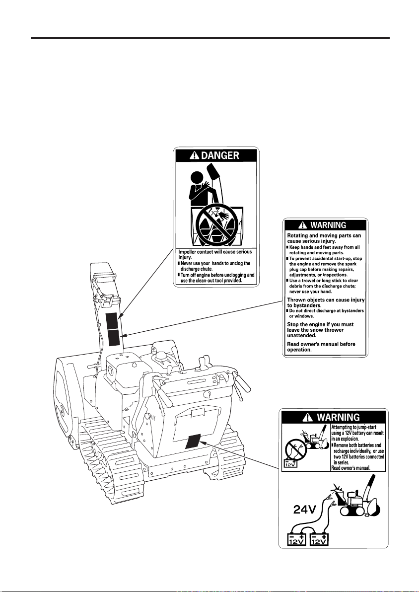
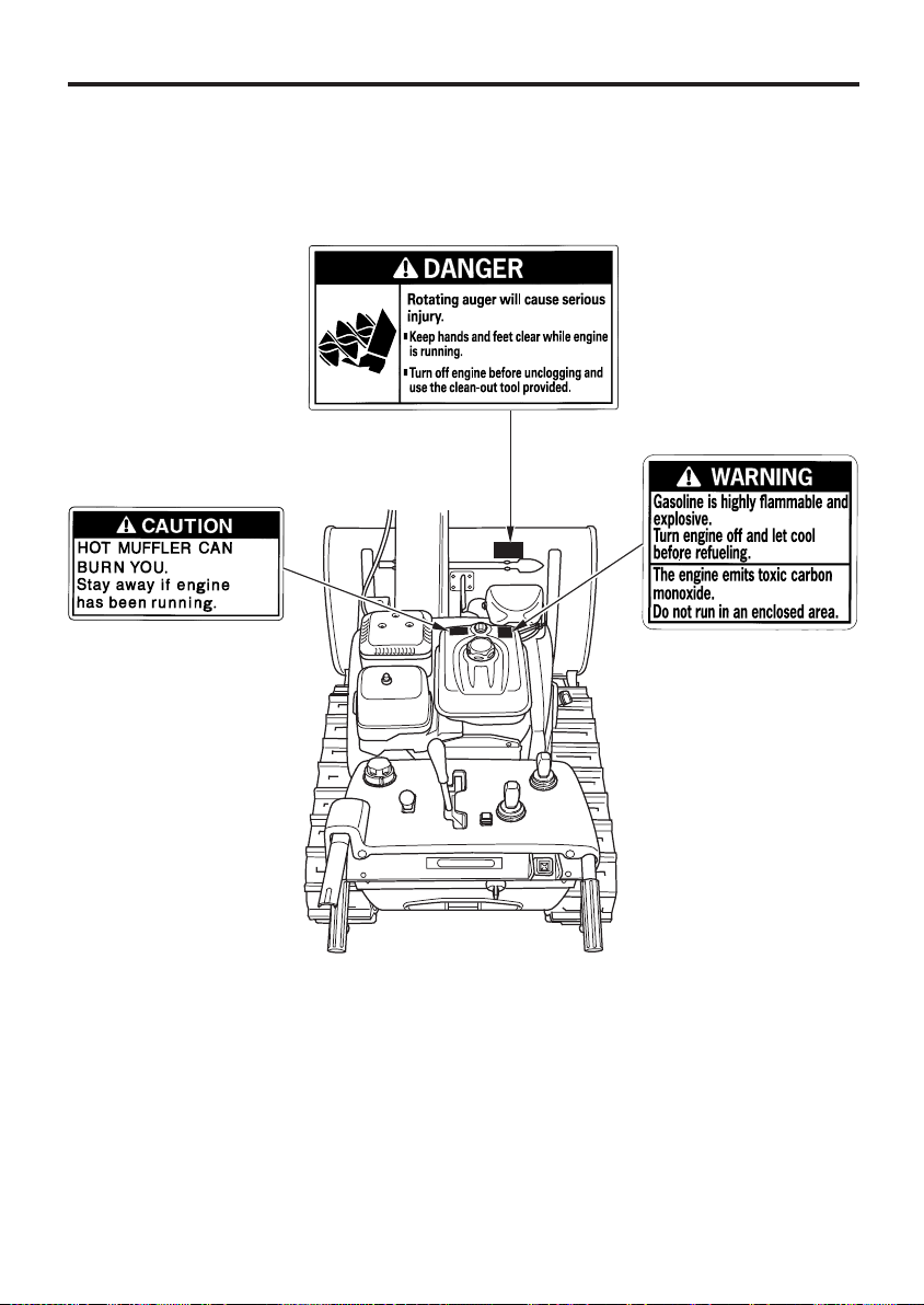
SAFETY LABEL LOCATIONS
These labels warn you of potential hazards that can cause serious
injury. Read them carefully.
If a label comes off or becomes hard to read, contact your Honda
dealer to purchase a replacement.
9
Page 12
SNOWBLOWER SAFETY
10
Page 13
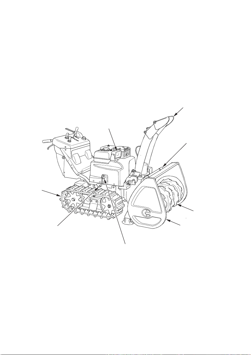
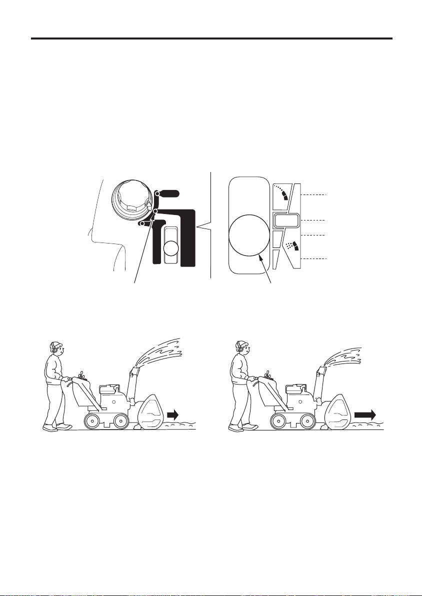
CONTROLS & FEATURES
COMPONENT & CONTROL LOCATIONS
Use the illustrations on these pages to locate and identify the most
frequently used controls.
DISCHARGE CHUTE
HEADLIGHT
SNOW CLEARING BAR
TRACK
ENGINE OIL DRAIN BOLT
AUGER
AUGER HOUSING
ENGINE OIL FILLER CAP/DIPSTICK
11
Page 14
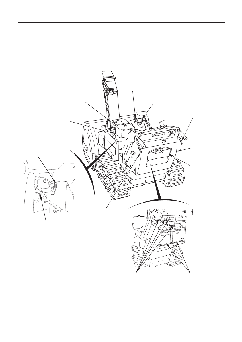
CONTROLS & FEATURES
FUEL GAUGE
SPARK PLUG CAP
FUEL VALVE LEVER
MANUAL START LEVER
MUFFLER
STEERING
LEVER (left)
FUEL TANK CAP
STEERING LEVER (right)
REAR COVER
TOOL BOX
12
FUSE BOXES
BATTERIES (12V 2)
×
Page 15
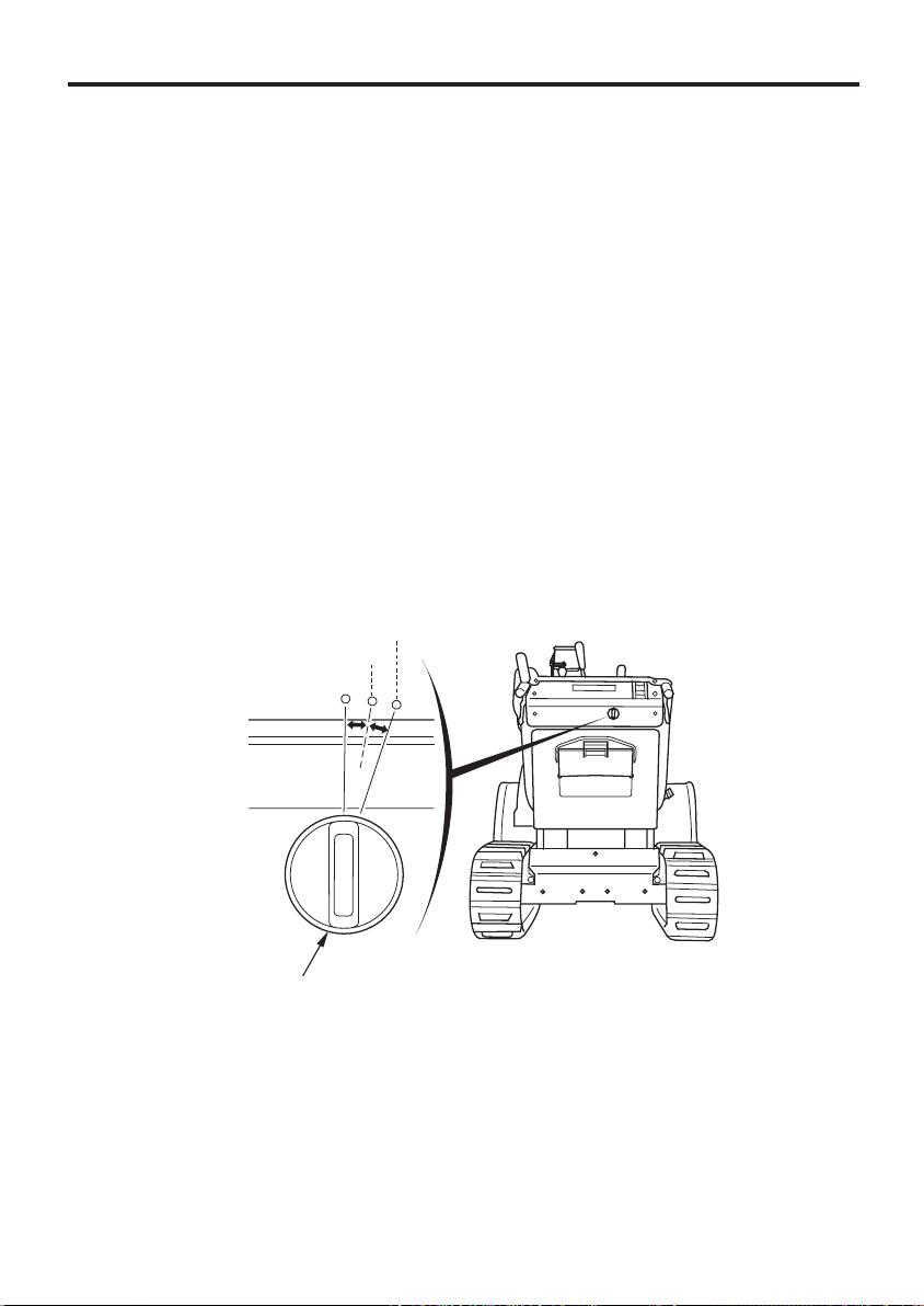
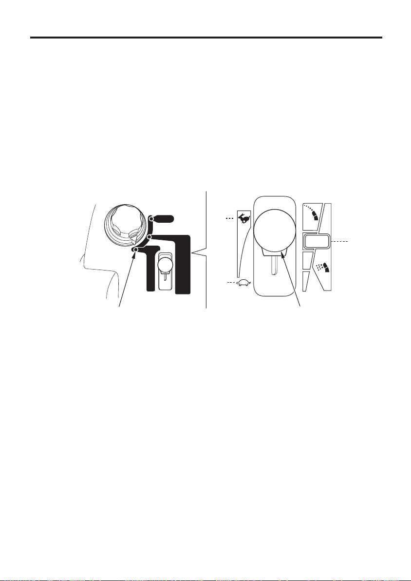
MODE SELECTOR SWITCH
CONTROLS & FEATURES
MAIN SHIFT LEVER
CHUTE CONTROL SWITCH
THROTTLE CONTROL
LEVER
DRIVE CLUTCH
LEVER
DRIVE CONTROL WARNING
INDICATOR (red)
DRIVE CONTROL WARNING
INDICATOR (orange)
AUGER HOUSING
CONTROL SWITCH
RESET SWITCH
AUGER CLUTCH
SWITCH
ENGINE SWITCH
BATTERY INDICATOR (orange)
OIL INDICATOR (red)
CHARGING INDICATOR (red)
13
Page 16
CONTROLS & FEATURES
CONTROLS
Engine Switch
The engine switch controls the ignition system. The key (if equipped)
can only be inserted and removed when turned to OFF.
−
OFF
ON
Engine switch position to stop the engine.
(The engine switch key can be removed/inserted with the switch
in this position.)
−
Engine switch position while the engine is running.
Each electric circuit comes on.
(It produces a clicking sound with the switch set in this position.)
START
−
Engine switch position to start the engine. The starter motor
turns. Release the engine switch key, and the engine switch
automatically returns to the ON position.
START
ON
OFF
ENGINE SWITCH
14
Page 17
CONTROLS & FEATURES
Fuel Valve Lever
The fuel valve opens and closes the fuel line leading from the fuel tank
to the carburetor. Make sure that the fuel valve is positioned exactly at
either the ON or OFF position. When the snowblower is not in use,
always leave the fuel valve in the OFF position to reduce the possibility
of fuel leakage.
ON
FUEL VALVE LEVER
OOFFFF
Manual Start Lever
This snowblower is equipped with the auto choke system. Do not need
to operate the manual start lever to start using the normal starting.
However, it may not function properly when foreign material (ice, etc.)
is stuck on the system.
If the engine does not start after 5 attempts, push and release the
manual start lever one time and try to start the engine (see page ).40
MANUAL START LEVER
OONN
((PPUUSSHH))
15
Page 18

CONTROLS & FEATURES
Mode Selector Switch
Use the mode selector switch to change the work mode (automatic
adjustment) of the snowblower. The work mode can be selected from
one of three modes: AUTO, POWER, or MANUAL.
MODE SELECTOR SWITCH
AUTO
MANUAL
POWER
16
Page 19

CONTROLS & FEATURES
Characteristics of AUTO mode:
Travel speed is automatically adjusted according to the workload,
which reduces the tendency of snow to pile up in front of the
snowblower.
Engine speed is automatically adjusted according to operating
conditions so the snow discharge distance remains constant.
The auger is automatically raised when the snowblower is reversing.
In case the auger clutch switch is in the ON position, the auger is
automatically returned to the original position when the
snowblower begins moving forward again.
Forward speed is set low. Select another mode to make the
snowblower travel faster.
Characteristics of POWER mode:
Travel speed is automatically adjusted according to the workload so
engine power can be maintained at or near the maximum level.
Engine speed is automatically adjusted according to operating
conditions so the snow discharge distance remains constant that
have been set with the throttle control lever.
The auger is automatically raised when the snowblower is reversing.
In case the auger clutch switch is in the ON position, the auger is
automatically returned to the original position when the
snowblower begins moving forward again.
17
Page 20

CONTROLS & FEATURES
Characteristics of MANUAL mode:
No automatic adjustment is made. Manually adjust the engine
speed and travel speed according to the workload.
Do not turn the mode selector switch to another position while the
snowblower is moving. The electronic control unit will interpret this as
a failure; the snowblower will stop moving and the auger will stop
turning.
When the snowblower and auger stop moving/turning, move the main
shift lever to the N (neutral) position, release the drive clutch lever
once, and then squeeze it again.
Check each part to verify it is in its proper position before resuming
operation.
18
Page 21

CONTROLS & FEATURES
Throttle Control Lever
Use the throttle control lever to adjust the engine speed and/or snow
discharge distance with the mode selector switch set at the POWER or
MANUAL position.
Note that the engine speed and snow discharge distance cannot be
adjusted by operating the lever when the AUTO mode is selected.
MANUAL
FAST
SLOW
THROTTLE CONTROL LEVER
POWER
4th (Long)
3rd
2nd
1st (Short)
Moving the throttle control lever to the FAST side increases both the
engine speed and snow discharge distance.
Moving the throttle control lever to the SLOW side decreases both the
engine speed and snow discharge distance.
19
Page 22
CONTROLS & FEATURES
POWER mode:
Travel speed is automatically reduced so that the engine speed and
snow discharge distance are held at the given speed and distance that
have been set with the throttle control lever.
Setting the discharge distance control lever in the second range from
the bottom clears snow the fastest (maximum snow-clearing
efficiency), but the snow discharge distance is shorter. Set the control
lever in most appropriate engine speed and snow discharge distance
for the work.
4th (Long)
3rd
2nd
1st (Short)
20
POWER mode
Long Short
THROTTLE CONTROL LEVER
Slow Fast
Page 23
CONTROLS & FEATURES
MANUAL mode:
When the workload increases while clearing the snow, the engine
speed and snow discharge distance drop below the given speed and
distance that have been set with the throttle control lever. Reduce the
workload applied to the snow clearing part of the snowblower to hold
the engine speed/snow discharge distance at the given speed/distance.
If you are not sure of the appropriate position to set the engine speed
and snow discharge distance, we recommend that you set the control
lever in the third position from the bottom (maximum power position).
Then, adjust the snow discharge distance at the desired position while
you are clearing the snow.
FAST
3rd
SLOW
MANUAL mode THROTTLE CONTROL LEVER
21
Page 24
CONTROLS & FEATURES
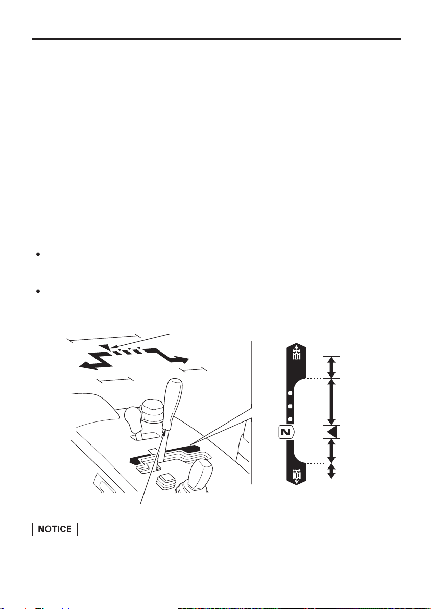
Main Shift Lever
Operate the main shift lever to drive the snowblower in forward or in
reverse direction.
The lever has two ranges, slow range and fast range.
The speed of the snowblower can be increased and decreased in any
of these two speed ranges.
To drive forward:
Move the main shift lever slowly forward from the N (neutral) position.
To reverse:
Move the main shift lever slowly rearward from the N (neutral)
position.
Set the main shift lever in the N (neutral) position while the
snowblower is not in operation.
Set the travel speed by setting the main shift lever to the desired
position within the low speed range according to the nature of the
snow, and clear the snow.
Set the travel speed according to the road surface condition and
environment before moving the snowblower.
SLOW RANGE
REVERSE
FAST
RANGE
MAIN SHIFT LEVER
N (neutral)
FORWARD
FAST
RANGE
FAST
SLOW
SLOW
FAST
FORWARD
FAST RANGE
SLOW RANGE
N (neutral)
SLOW RANGE
FAST RANGE
REVERSE
This snowblower has a function that limits the maximum speed in
reverse. Consult to your authorized Honda snowblower dealer for
details.
22
Page 25
CONTROLS & FEATURES
Drive Clutch Lever
Squeezing the drive clutch lever drives the snowblower forward or
backward with the main shift lever operation.
If you are moving the snowblower from one place to another, squeeze
the drive clutch lever only.
DRIVE CLUTCH LEVER
DISENGAGED
ENGAGED
Auger Clutch Switch
If you continue pressing the auger clutch switch, the indicator comes
on as a reminder and the snow blowing mechanism starts. Releasing
the switch stops the mechanism and the indicator goes off. With the
drive clutch lever squeezed, the auger clutch switch will be on
continuously by pressing it once. Releasing the drive clutch lever
stops the snowblower from moving and stops the auger.
If the indicator (green) does not come on and neither the auger nor
blower turns by pressing the auger clutch switch, have your
authorized Honda snowblower dealer check the snowblower.
Both the auger and blower stop turning by pushing the auger clutch
switch for 4 seconds or more.
AUGER CLUTCH SWITCH
OONN
OOFFFF
23
Page 26
CONTROLS & FEATURES
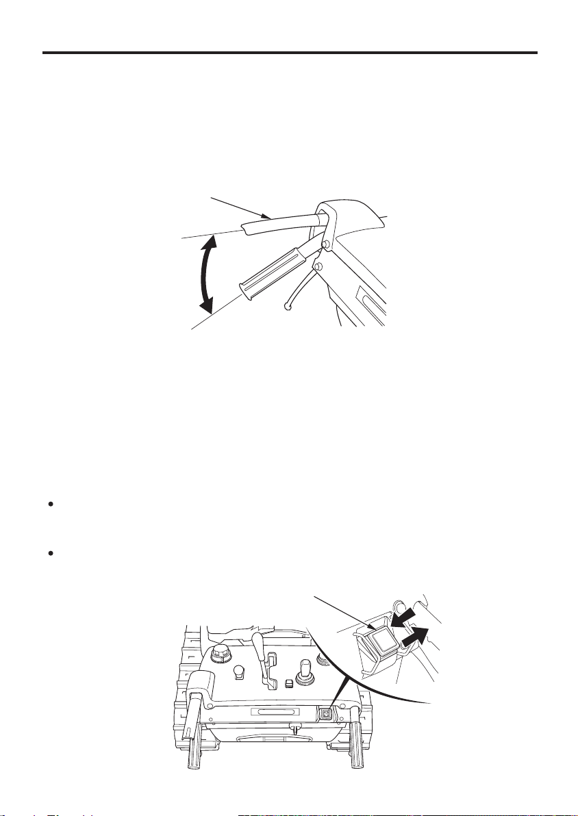
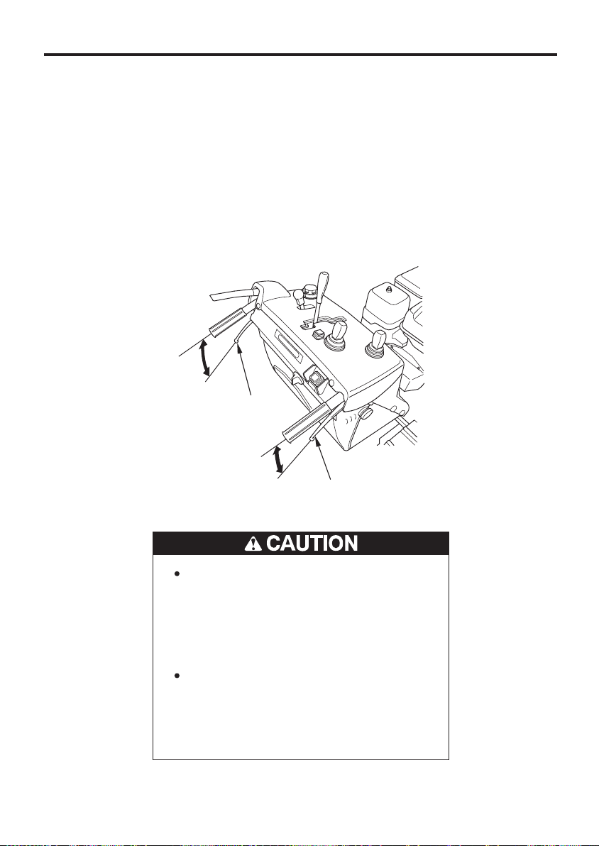
Steering Lever
Use the steering lever to turn the snowblower.
Squeeze the steering lever on the side to which you want to turn the
snowblower. Note that the radius of turn can be adjusted depending
on a position of the main shift lever and the amount of squeeze of the
steering lever.
To turn to the right: Squeeze the right steering lever.
To turn to the left: Squeeze the left steering lever.
STEERING LEVER
(left)
24
STEERING LEVER
(right)
Reduce speed when making turns.
Use extra care when making turns
as the location of the handle and
panels relative to the operator will
change suddenly and can cause
injury.
Note that the road condition (e.g.
asphalt road, covered with snow,
slope, bumpy surface, etc.) can
affect the radius of turn and your
steering feel.
Page 27
CONTROLS & FEATURES
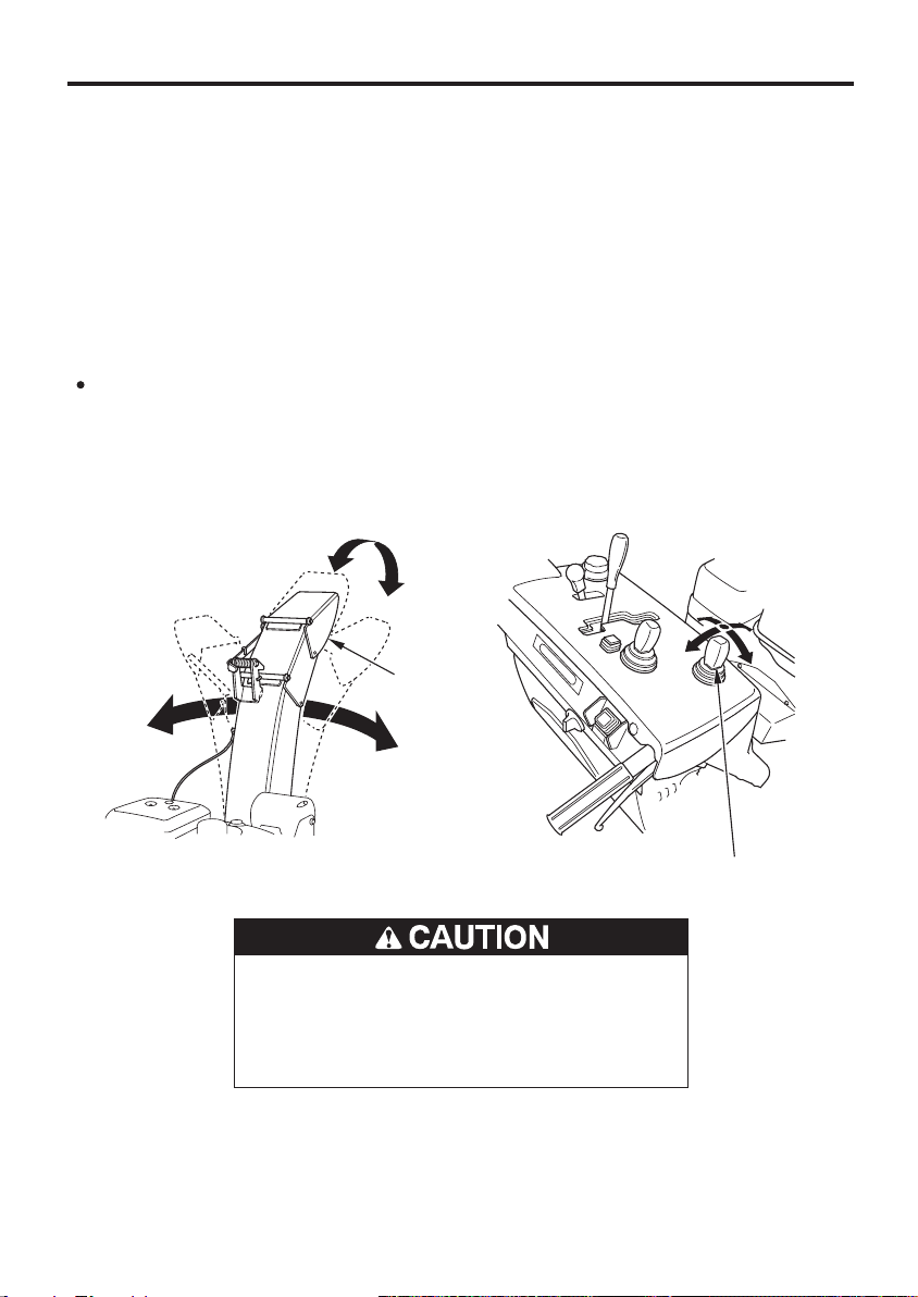
Chute Control Switch
The snow discharge direction and angle can be adjusted by operating
the chute control switch.
Turn the engine switch to the ON position and operate the chute
control switch to adjust the snow discharge direction and angle up/
down or right/left (see pages , and ).
Operate the chute control switch while the engine is running.
Operating the chute control switch while the engine is OFF may cause
a dead battery.
Do not keep operating the chute control switch with the chute/chute
guide motor locked. The protection function gets armed, preventing
the chute from moving. Wait a few minutes before operating the
chute control switch again.
HIGH
555249
LEFT
LOW
CHUTE
RIGHT
HHIIGGHH
CHUTE CONTROL SWITCH
Adjust the snow discharge direction
and angle with care not to hit bystanders, windows, and other
objects with thrown snow.
LLEEFFTT
LLOOWW
RRIIGGHHTT
25
Page 28
CONTROLS & FEATURES
Auger Housing Control Switch
Operate the auger housing control switch to adjust the auger housing
height and tilt angle (see pages and for adjustment).
Operate the auger housing control switch while the engine is running.
Operating the auger housing control switch while the engine is OFF
maycauseadeadbattery.
45 47
LLEEFFTT
UUPP
HIGH (UP)
MIDDLE
LOW (DOWN)
DDOOWWNN
RRIIGGHHTT
AUGER HOUSING CONTROL SWITCH
RIGHT
LEFT
26
AUGER HOUSING AUGER HOUSING
Page 29

CONTROLS & FEATURES
Reset Switch
Use the reset switch to return the auger housing to the reset height
position (current set position). This switch is convenient to move the
auger housing by operating the auger housing control switch and to
return the auger housing to the original height position. The reset
height position has been set at the factory in the position where the
snow clearing part contacts the ground with the snowblower set on a
level ground.
The reset height position can be changed (see page for reset height
position changing procedure).
The reset switch can not reset the right and left direction of the auger
housing angle to the reset position.
OOFFFF
OONN
63
RESET SWITCH
27
Page 30
CONTROLS & FEATURES
FEATURES
Drive Control Warning Indicator (red)
The drive control warning indicator (red) turns on for a few seconds
when the engine switch is turned from OFF to ON. The indicator goes
off while the engine is running. If the indicator does not come on when
starting and it comes on or blinks while the engine is running, contact
your authorized Honda snowblower dealer.
DRIVE CONTROL WARNING INDICATOR (red)
Drive Control Warning Indicator (orange)
The drive control warning indicator (orange) turns on when the engine
switch is turned from OFF to ON. The indicator (orange) turns off when
the engine is started. The indicator goes off while the engine is
running. If the indicator does not come on when starting and it comes
on or blinks while the engine is running, contact your authorized
Honda snowblower dealer.
If the orange indicator blinks, the drive control protection system may
be activated because of such things as a drive control system problem
or overload. See page for the protection system.60
DRIVE CONTROL WARNING INDICATOR (orange)
28
Page 31

CONTROLS & FEATURES
Charging Indicator
The charging indicator (red) turns on when the engine switch is turned
from OFF to ON. The indicator turns off when the engine is started. If
the indicator does not come on when starting or comes on while the
engine is running, contact your authorized Honda snowblower dealer.
CHARGING INDICATOR (red)
Oil Indicator
The oil indicator (red) comes on when the engine oil level is low.
Turn the engine switch to the ON position. If it is normal, the oil
indicator (red) comes on for a few seconds and then it goes off. The
engine does not start unless the oil indicator (red) goes off. Check the
engine oil level (see page ).
If the oil indicator (red) comes on while the snowblower is running,
move the snowblower immediately to a safe, level place, stop the
engine, and check the engine oil level (see page ).
79
79
Do not keep operating the snowblower with the oil indicator (red) on. It
will cause the engine to malfunction.
OIL INDICATOR (red)
29
Page 32

CONTROLS & FEATURES
Battery Indicator
The battery indicator will blink when the voltage is getting low (see
pages and for battery charge or replacement).
The battery indicator (orange) turns on for a few seconds when the
engine switch is turned from OFF to ON and then go off. The indicator
should be off when the engine is running. If the indicator does not
come on when starting, or it comes on while the engine is running,
contact your authorized Honda snowblower dealer.
Even if the engine is not running, the indicator will blink when the
engine switch is in the ON position (The engine switch should be
turned OFF immediately).
91 94
BATTERY INDICATOR (orange)
30
Page 33

CONTROLS & FEATURES
Fuel Gauge
The fuel gauge indicates the amount of fuel in the tank. When the fuel
gauge needle enters the EMPTY range, refill the tank as soon as
possible.
FUEL GAUGE
Headlight
The headlight turns on when the engine switch is in the ON position.
The battery may become discharged when the light is ON while the
engine is OFF.
If the headlight does not come on, the battery might be faulty or the
bulb might be blown. Check the battery.
HEADLIGHT
31
Page 34

CONTROLS & FEATURES
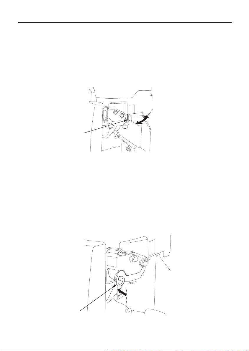
Wheel Pin
Do not remove the wheel pins with
the snowblower on a slope. The
snowblower might move
unintentionally, causing serious
injury.
Before removing the wheel pins, place the snowblower on a level
surface. Stop the rotating parts, stop the engine, and remove the
engine switch key.
Remove the cotter pins and wheel pins from the rear right and left
wheels. This allows the track to rotate freely so the operator can move
the snowblower if the motor malfunctions. Use a new cotter pin when
replacing the wheel pin.
WHEEL PIN
32
COTTER PIN
Page 35

CONTROLS & FEATURES
Snow Clearing Bar
If the snow discharge chute or snow blowing mechanism becomes
clogged, stop the engine and use this bar to unclog it.
SNOW CLEARING BAR
Before removing clogged snow, be
sure to stop the engine, and make
sure that all rotating parts have
come to a complete stop. Remove
the key from the engine switch.
Failure to do so can cause serious
injury or death.
33
Page 36

CONTROLS & FEATURES
Skid, Scraper
Adjust the skid and the scraper according to the road surface condition
where you are to clear the snow. Use the skid to determine the height
from the ground to the auger, and adjust the scraper to make the snow
surface even (see page ).42
AUGER
34
SKID
SCRAPER
Page 37

BEFORE OPERATION
ARE YOU READY TO GET STARTED?
Your safety is your responsibility. A little time spent in preparation will
significantly reduce your risk of injury.
Knowledge
Read and understand this manual. Know what the controls do and
how to operate them.
Familiarize yourself with the snowblower and its operation before you
begin using it. Know how to quickly shut off the snowblower in case of
an emergency.
IS YOUR SNOWBLOWER READY TO GO?
For your safety, and to maximize the service life of your equipment, it
is very important to take a few moments before you operate the
snowblower to check its condition. Be sure to take care of any problem
you find, or have your servicing dealer correct it, before you operate
the snowblower.
Improperly maintaining this
snowblower, or failing to correct a
problem before operation, could
cause a malfunction in which you
could be seriously injured.
Always perform a pre-operation
inspection before each operation,
and correct any problem.
Before beginning your pre-operation checks, be sure the snowblower
is on a level surface and the engine switch is in the OFF position.
35
Page 38

BEFORE OPERATION
Check the General Condition of the Snowblower:
Look around and underneath the snowblower for signs of oil or
gasoline leaks.
Check the auger housing and the discharge chute for accumulation
of packed snow or ice. Clean the auger housing and discharge chute
before starting the snowblower.
Look for signs of damage.
Check each control for proper operation.
Check the battery electrolyte level (see page ).
Check the auger and blower for loose or broken bolts. If broken,
replace them with new ones (see page ).
Check the skid and scraper (see page ).
Check that all nuts, bolts, and screws are tightened.
Check that the indicators work properly.
Check the entire machine for any other faults that might have been
caused previously.
Check the Engine
Check the oil level (see page ).
Check the fuel level (see page ). Starting with a full tank will help
to eliminate or reduce operating interruptions for refueling.
79
77
42
89
85
36
Page 39

BEFORE OPERATION
CHECK YOUR WORK AREA
For your safety and the safety of others, always inspect the area before
operating the snowblower.
Objects
Anything which can be picked up by the augers and thrown is a
potential hazard to you and others. Thoroughly inspect the area where
the equipment is to be used and remove all doormats, sleds, boards,
wires, stones, and nails, and remove them from the work area.
People and Pets
People and animals near the work area can move into your
snowblowers path or into a position where they could be struck by
thrown objects. Clear the area of people, especially children, and pets.
Their safety is your responsibility.
Work Area
Check the condition of the snow. Adjust your snowblower ground
speed (not engine speed) and snowblowing swath accordingly.
Check the skid for proper adjustment. Adjust the skid to obtain the
auger ground clearance for the type of surface the snowblower will be
operated over (see page ).
Carefully check the area before backing the snowblower.
42
37
Page 40

OPERATION
SNOWBLOWING PRECAUTIONS
Before operating the snowblower for the first time, please review both
the
SNOWBLOWER SAFETY
OPERATION
Even if you have operated other snowblowers, take time to become
familiar with how this snowblower works, and practice in a safe area
until you build up your skills.
Never tamper with or alter any of the controls or safety devices on the
snowblower.
For your safety, do not start or operate the engine in an enclosed area
such as a garage. Your snowblower’s exhaust contains poisonous
carbon monoxide gas that can collect rapidly in an enclosed area and
cause illness or death.
chapter (see page ).
Exhaust contains poisonous carbon
monoxide gas that can build up to
dangerous levels in closed areas.
Breathing carbon monoxide can
cause unconsciousness or death.
chapter (see page ) and the
35
6
BEFORE
38
Never run the generator in a closed,
or even partly closed area where
people may be present.
Page 41

OPERATION
STARTING THE ENGINE
Turn the fuel valve lever to the ON position. Be sure that the drain
1.
knob is tightened securely.
FUEL VALVE LEVER
ON
DRAIN KNOB
Set the main shift lever in the N (neutral) position.
2.
MAIN SHIFT LEVER
N (neutral)
FORWARD
FAST
SLOW
N (neutral)
SLOW
FAST
REVERSE
39
Page 42

OPERATION
Turn the engine switch to the START position and release the switch
3.
key after the engine starts. The switch automatically returns to the
ON position.
SSTTAARRTT
ON
ENGINE SWITCH KEY
ENGINE SWITCH
If the engine does not start within 5 seconds after cranking the
starter, wait for about 10 seconds and restart the engine.
Note that the starter does not crank when the auger clutch switch
or drive clutch lever is operated (engine start interlock).
This snowblower is equipped with the auto choke system.
However, it may not function properly when foreign material (ice,
etc.) is stuck on the system.
If the engine does not start after 5 attempts, push and release the
manual start lever one time and try to start the engine.
If the engine still does not start, push and hold the manual start
lever and try again.
OONN
((PPUUSSHH))
MANUAL START LEVER
40
Page 43

OPERATION
After starting the engine, check that the engine speed is stabilizing.
4.
Move the throttle control lever to the SLOW position gradually and
warm up the engine to the normal operating temperature.
SLOW
THROTTLE CONTROL LEVER
41
Page 44

OPERATION
OPERATING THE CONTROLS FOR CLEARING SNOW
Before operating this equipment you should read and understand
the
SNOWBLOWER SAFETY
Efficiency of the snow removal work is significantly affected by the
snow condition (e.g. dry, wet etc.). Adjust the skid position, the
scraper position, and the auger housing height as needed for
optimum snow removal.
Skid and Scraper
Adjust the skid for the auger housing ground clearance best suited
to your snow removal conditions.
1.
Hold the auger housing horizontally and lower the auger on the
ground by operating the auger control switch.
2.
Turn the engine switch OFF and remove the key from the engine
switch.
on page through .
610
3.
Loosen the bolts and adjust the skid and scraper height in
accordance with the road surface condition where you are to clear
the snow (see pages and ).
43 44
BOLTS
AUGER
SKID SCRAPER
42
Page 45

OPERATION
Adjust the skid equally on both sides.
Be sure to tighten the skid and scraper bolts securely after making
adjustment.
Do not use the snowblower on rough or uneven surfaces with the
auger ground clearance set for hard snow or surfaces.
This may cause serious damage to the snow blowing mechanism.
Adjust the skid and scraper in the following cases
When the auger interferes with the road surface while it is turning:
When clearing the snow from the graveled road:
Raise the auger approximately 0.5 in (12 mm) from the ground
and secure the skid in this position.
Secure the scraper by raising it 0.3 in (7 mm) from the ground.
Do not clear the snow thoroughly from the ground. Leave some
on the ground to prevent gravel and other foreign material being
caught in the auger.
SKID
SCRAPER
0.3 in (7 mm) min. Approx. 0.5 in (12 mm) min.
AUGER
To break down the hardened snow that dropped from the roof:
When the snow is too hard to dig in, making the snowblower rise
on the snow:
Raise the skid and scraper to the uppermost position of the
adjustment range with the auger in contact with the ground, and
secure the skid and scraper in position.
SKID
Raise to the uppermost
position.
SCRAPER
AUGER
Note that the road surface can be damaged and stones can be thrown
out of the auger if it comes in contact with the ground. Return the skid
and scraper to the original position when operating the snowblower
under normal conditions.
43
Page 46

OPERATION
To clear the snow more neatly:
Bring the skid to be in contact with the ground with the auger
raised approximately 0.4 in (10 mm) from the ground. Secure the
skid in this position.
Secure the scraper by bringing it in contact with the ground.
AUGER
SKID
Approx. 0.4 in (10 mm)
SCRAPER
Factory pre-set clearance:
At the scraper (A):
At the auger (B):
−−
0.1 0.3 in (3 7 mm)
−−
0.3 0.5 in (8 12 mm)
44
SKID
SCRAPER
AUGER
AB
Page 47

OPERATION
Auger Housing Height
Operate the auger housing control switch back and forth. The auger
1.
housing height can be adjusted without discrete steps.
To raise: Pull the auger housing control switch to UP.
To lower: Push the auger housing control switch to DOWN.
Release the auger housing control switch, and the auger housing is
2.
secured in the position.
HIGH:
MIDDLE:
LOW:
UUPP
Use this position when clearing the snow in steps and use
it when reversing or driving the snowblower. (When the
mode selector switch is AUTO or POWER, use this
position when reversing the snowblower.)
Position for normal clearing. (Use this position to clear
the snow normally.)
Position for clearing hardened snow. (Use this position
when the snow you are to clear is hardened and the snow
clearing part of the snowblower tends to get raised.)
DDOOWWNN
HIGH (UP)
MIDDLE
AUGER HOUSING
CONTROL SWITCH
AUGER HOUSING
LOW (DOWN)
45
Page 48

OPERATION
Use the LOW position (i.e. position for clearing hardened snow) only
for clearing hardened snow. Do not set the auger housing in this
position while clearing soft snow or clearing on a bumpy road. This
can damage the road surface or cause stones to be thrown out of the
auger, which is very dangerous. Also, it can cause excessive wear and
damage to the snow clearing part of the snowblower.
When the mode selector switch is in AUTO or POWER, the auger
housing automatically rises while going in reverse.
In case the auger clutch switch is in the ON position, the auger is
automatically returned to the original position when the
snowblower is transporting forward again.
If you want to stop the automatic movement of the auger housing,
change the mode selector switch to the ‘‘MANUAL’’ position.
To stop the automatically movement of the auger housing, push the
control switch once to the opposite direction of the movement.
Frequent operation of the auger housing control switch activates the
protection function and makes the drive control warning indicator
(orange) blink, which prevents you from adjusting the snow clearing
part of the snowblower. Stop operating the auger housing control
switch and wait a few seconds before operating the switch again.
46
Page 49

OPERATION
Auger Housing Tilt Angle
When the auger housing is tilted during snow removal, adjust the tilt
angle by operating the auger housing control switch.
When the auger is tilted toward the right: Move the switch toward the
right.
When the auger is tilted toward the left: Move the switch toward the
left.
LLEEFFTT
RRIIGGHHTT
RIGHT
LEFT
AUGER HOUSING
CONTROL SWITCH
AUGER HOUSING
The control motor may overheat, which can cause a malfunction of
the protector circuit and motor and make the auger housing
unadjustable.
Stop operating the switch when the auger housing reaches the right
end or left end position. Do not hold the auger housing control
switch operated.
47
Page 50

OPERATION
Operation
1.
Start the engine (see pages through ).
2.
Select the snow clearing work mode.
1.
Check that the main shift lever is in the N (neutral) position.
−
2.
Select the appropriate work mode to clear the snow by turning
−
39 41
the mode selector switch to either the MANUAL, POWER, or
AUTO position.
Note that the operation and performance of the snowblower differ
according to the work mode you select. Select the appropriate work
mode for your situation (see pages and for the characteristics
17 18
of each mode).
MODE SELECTOR SWITCH
AUTO
MANUAL
POWER
Tips for selecting the work mode:
AUTO mode: see page .
1)
Not familiar with operating the snowblower.
2)
Does not want to operate the various switches while clearing the
49
snow.
3)
Want to clear the snow as quietly as possible.
4)
Want the auger to rise up as little as possible.
POWER mode: see page .
1)
Want to adjust the traveling speed automatically according to the
52
workload while clearing the snow.
2)
Want to throw the snow far from the snowblower.
3)
Want to finish clearing the snow as quickly as possible.
MANUAL mode: see page .
55
Want to operate the switches as you like.
48
Page 51

OPERATION
Do not turn the mode selector switch to another position while the
snowblower is moving. The electronic control unit will interpret this as
a failure; the snowblower will stop moving and the auger will stop
turning.
When the snowblower and auger stop moving/turning, move the main
shift lever to the N (neutral) position, release the drive clutch lever
once, and then squeeze it again.
Check each part to verify it is in its proper position before resuming
operation.
3a.
ClearinginAUTOmode
Setting the mode selector switch at the AUTO position can
simplify clearing the snow. AUTO mode keeps the auger from
rising, adjusts the engine speed automatically, etc.
1)
Operate the chute control switch to
adjust the snow discharge direction
andangle(seepage ).
25
CHUTE CONTROL SWITCH
AUGER HOUSING
CONTROL SWITCH
RESET SWITCH
2)
Operate the auger housing control
switch to adjust the auger to be
parallel to the road surface (see
pages and ).
45 47
You can return the auger to the
initial height position by pushing
the reset switch.
If you return the auger to the
initial height position by pushing
the reset switch, the auger can hit
against the road surface or can be
raised from the road, resulting in
some snow left on the ground,
depending on the road condition
and the position of the
snowblower. Adjust the auger
height position as needed.
49
Page 52

OPERATION
DRIVE CLUTCH
LEVER
MAIN SHIFT LEVER
AUGER CLUTCH SWITCH
N (neutral)
3)
Check that the main shift lever is in
the N (neutral) position and squeeze
the drive clutch lever.
4)
Push the auger clutch switch to
operate on the auger and blower.
The indicator (green) comes on
when you push the auger clutch
switch.
When the auger clutch switch is
pushed for four seconds or longer,
the protection function gets
armed. This stops the auger and
blower from turning.
The auger and blower keep
turning while the drive clutch
lever is squeezed. Push the auger
clutch switch again to stop the
auger and blower. (Interlocking
operation of the drive clutch lever
and auger clutch switch)
50
The auger and blower will start to
turn when the drive clutch lever and
auger clutch switch is operated.
Check around the snowblower for
safety before operating the lever
and switch.
Page 53

MAIN SHIFT LEVER
MAIN SHIFT LEVER
DRIVE
CLUTCH
LEVER
LOW
RANGE
FAST
RANGE
OPERATION
5)
Move the main shift lever fully to
the end of the forward low speed
range slowly and clear the snow.
When the auger hits against the
road or inclines to a side, adjust
the auger housing position by
operating the auger housing
control switch.
When the snow is small in
volume or light in nature, move
the main shift lever to the high
speed side. Perform minor
adjustment of the main shift lever
to stabilize the operating speed if
necessary.
6)
When the drive clutch lever is
released, the auger clutch switch
indicator (green) goes off, both the
auger and blower stop turning, and
the snowblower stops moving.
AUGER CLUTCH SWITCH
Turn the auger clutch switch OFF if
you move the snowblower without
performing the snowblowing
operation.
51
Page 54

OPERATION
3b.
Clearing in POWER mode
With the mode selector switch in the POWER position you can
adjust the engine speed and snow discharge distance. Use the
throttle control lever to adjust the engine speed, which determines
how fast snow is picked up and how far it is thrown. Use the chute
control switch to adjust height and direction of the snow
discharge.
Note that the throttle control lever only functions after the auger
is turning. The engine speed is maintained automatically in
POWER mode.
THROTTLE CONTROL LEVER
POWER mode
CHUTE CONTROL SWITCH
RESET SWITCH
3rd
AUGER HOUSING
CONTROL SWITCH
1)
Set the throttle control lever in the
third position from the bottom.
2)
Operate the chute control switch to
adjust the snow discharge direction
andangle(seepage ).
3)
Operate the auger housing control
25
switch to adjust the auger to be
parallel to the road surface (see
pages and ).
4745
You can return the auger to the
initial height position by pushing
the reset switch.
If you return the auger to the
initial height position by pushing
the reset switch, the auger can hit
against the road surface or can be
raised from the road, resulting in
some snow left on the ground,
depending on the road condition
and the position of the
snowblower. Adjust the auger
height position as needed.
52
Page 55

DRIVE CLUTCH
LEVER
MAIN SHIFT LEVER
AUGER CLUTCH SWITCH
N (neutral)
OPERATION
4)
Check that the main shift lever is in
the N (neutral) position and squeeze
the drive clutch lever.
5)
Push the auger clutch switch to
operate on the auger and blower.
The indicator (green) comes on
when you push the auger clutch
switch.
When the auger clutch switch is
pushed for four seconds or longer,
the protection function gets
armed. This stops the auger and
blower from turning.
The auger and blower keep
turning while the drive clutch
lever is squeezed. Push the auger
clutch switch again to stop the
auger and blower. (Interlocking
operation of the drive clutch lever
and auger clutch switch)
The auger and blower will start to
turn when the drive clutch lever and
auger clutch switch is operated.
Check around the snowblower for
safety before operating the lever
and switch.
53
Page 56

OPERATION
MAIN SHIFT LEVER
MAIN SHIFT LEVER
THROTTLE CONTROL LEVER
LOW
RANGE
FAST
RANGE
6)
Move the main shift lever fully to
the end of the forward low speed
range slowly and clear the snow.
When the auger hits against the
road or inclines to a side, adjust
the auger housing position by
operating the auger housing
control switch.
When the snow is small in
volume or light in nature, move
the main shift lever to the high
speed side. Perform minor
adjustment of the main shift lever
to stabilize the operating speed if
necessary.
7)
After stabilizing the operating speed,
adjust the snow discharge distance
by operating the throttle control
lever as needed.
Traveling speed will decrease by
increasing the snow discharge
distance, while the speed will
increase by decreasing the snow
discharge distance. Adjust the
snow discharge distance by
operating the throttle control
lever as needed.
DRIVE
CLUTCH
LEVER
54
AUGER CLUTCH SWITCH
8)
When the drive clutch lever is
released, the auger clutch switch
indicator (green) goes off, both the
auger and blower stop turning, and
the snowblower stops moving.
Turn the auger clutch switch OFF if
you move the snowblower without
performing the snowblowing
operation.
Page 57

OPERATION
3c.
Clearing in MANUAL mode
Nothing is controlled automatically when the mode selector
switch is set at the MANUAL position. Engine speed and operating
speed can be adjusted freely by selecting the MANUAL mode.
THROTTLE CONTROL LEVER
MANUAL mode
RESET SWITCH
N (neutral)
3rd
CHUTE CONTROL
SWITCH
AUGER HOUSING
CONTROL SWITCH
1)
Set the throttle control lever in the
third position from the bottom.
2)
Operate the chute control switch to
adjust the snow discharge direction
andangle(seepage ).
3)
Operate the auger housing control
25
switch to adjust the auger to be
parallel to the road surface (see
pages and ).
45 47
You can return the auger to the
initial height position by pushing
the reset switch.
If you return the auger to the
initial height position by pushing
the reset switch, the auger can hit
against the road surface or can be
raised from the road, resulting in
some snow left on the ground,
depending on the road condition
and the position of the
snowblower. Adjust the auger
height position as needed.
DDRRIIVVEE CCLLUUTTCCHH
LLEEVVEERR
MAIN SHIFT LEVER
4)
Check that the main shift lever is in
the N (neutral) position and squeeze
the drive clutch lever.
55
Page 58

OPERATION
AUGER CLUTCH SWITCH
5)
Push the auger clutch switch to
operate on the auger and blower.
The indicator (green) comes on
when you push the auger clutch
switch.
When the auger clutch switch is
pushed for four seconds or longer,
the protection function gets armed.
This stops the auger and blower
from turning.
The auger and blower keep turning
while the drive clutch lever is
squeezed. Push the auger clutch
switch again to stop the auger and
blower. (Interlocking operation of
the drive clutch lever and auger
clutch switch)
The auger and blower will start to
turn when the drive clutch lever and
auger clutch switch is operated.
Check around the snowblower for
safety before operating the lever
and switch.
MAIN SHIFT LEVER
56
FAST
SLOW
SLOW
FAST
FAST
RANGE
LOW
RANGE
Adjust the operating speed by moving
6)
the main shift lever to a position
within the slow speed range
according to the volume and nature of
the snow, and clear the snow.
Even when you are clearing the
snow, adjust the operating speed as
needed by operating the main shift
lever according to the change of the
volume and nature of the snow.
When the snow is small in volume
or light in nature, move the main
shift lever to the high speed side.
Perform minor adjustment of the
main shift lever to stabilize the
operating speed if necessary.
Page 59

DRIVE
CLUTCH
LEVER
AUGER CLUTCH SWITCH
OPERATION
7)
When the drive clutch lever is
released, the auger clutch switch
indicator (green) goes off, both the
auger and blower stop turning, and
the snowblower stops moving.
Turn the auger clutch switch OFF if
you move the snowblower without
performing the snowblowing
operation.
57
Page 60

OPERATION
Turning the Snowblower
You can change the direction of your snowblower while moving by
squeezing either the right or left steering lever. You can make two
types of turns, normal turn and turn on the spot (to correct the driving
direction on the spot), depending on the position of the main shift
lever and the degree of squeezing pressure on the steering lever.
To turn to the left: Squeeze the steering lever (left).
To turn to the right: Squeeze the steering lever (right).
Normal turn
To make a large turn: Squeeze a steering lever lightly.
To make a small turn: Squeeze a steering lever fully.
Turn on the spot
Squeeze the steering lever fully on the side to which you want to
turn the snowblower while driving forward at low speed, and you
can make a turn on the spot (i.e. correct the direction on the spot).
This function facilitates changing or correcting the direction in a
narrow place such as when moving the snowblower in or out of the
storage.
N (neutral)
STEERING LEVER
(left)
MAIN SHIFT
LEVER
58
SLOW RANGE
REVERSE
FFAASSTT RRAANNGGEE
FORWARD
FFAASSTT RRAANNGGEE
STEERING LEVER (right)
FAST
SLOW
SLOW
FAST
FORWARD
REVERSE
FAST RANGE
(normal turn)
SLOW RANGE
(possible a turn
on the spot)
N (neutral)
(normal turn)
Page 61

OPERATION
Example: To turn to the left (To turn to the right is the mirror image of
the illustrations.)
Normal turn (Left steering lever squeezed halfway)
OPERATOR
STEERING LEVER
CENTER OF
SNOW BLOWER
SMALL
LARGE
WHEN DRIVING FORWARD
WHEN REVERSING
LARGE SMALL
(TURN RADIUS)
SMALLLARGE
RADIUS OF TURN
RADIUS OF TURN
CENTER OF
SNOW BLOWER
59
Page 62

OPERATION
Turn on the spot (Steering lever fully squeezed)
The track on the side to which you are to turn turns in the reverse
direction, which makes the snowblower turn on the spot (corrects
the direction on the spot).
CENTER OF SNOW BLOWER
OPERATOR
CENTER OF TURN
OPERATOR
Track turns in
the reverse
direction.
STEERING LEVER
(Squeeze fully)
Track turns in
the normal
direction.
Drive motor control protection system
This snowblower is designed to drive with the motor power. When an
excessive load is applied to the motor, which depends on an operation
condition of the snowblower, the protection circuit is armed making
the drive control warning indicator (orange) come on and blink and
possibly slowing down or stopping the snowblower.
If this symptom occurs, turn the engine switch to the OFF position and
wait until the motor cools down before restarting the engine. If the
drive control warning indicator (orange) does not come on and blink
this time, it indicates that the snowblower has been restored to its
normal condition and you can continue clearing the snow.
Note that the protection system functions frequently if the motor is
under an excessive load. Adjust the load to a proper level.
The snowblower might be faulty if the engine does not restart or the
drive control warning indicator (orange) blinks when restarting the
engine. Move the snowblower to a safe place by removing the wheel
pins from the tracks and check for the trouble by referring to the
symptom-to-troubleshooting table (see pages and ). Have your
112 113
authorized Honda snowblower dealer check and repair your
snowblower if necessary.
See page for wheel pin removal.
124
60
Page 63

OPERATION
Battery Run System
Use the battery run system to drive the snowblower in case the engine
does not start.
1.
Set the main shift lever in the N (neutral) position.
−
2.
Release the drive clutch lever to set it in the STOP position.
−
3.
Turn the engine switch to the ON position.
−
4.
Squeeze the right and left steering levers simultaneously for
−
approximately 3 seconds.
DRIVE CLUTCH LEVER
STEERING LEVER
(left)
ENGINE SWITCH
STEERING LEVER (right)
5.
Both the drive control warning indicator (red) and the drive control
−
MAIN SHIFT LEVER
warning indicator (orange) blink after squeezing the right and left
steering levers for approximately 3 seconds. Squeeze the drive
clutch lever when the indicators blink.
If the drive clutch lever and the main shift lever are not operated
within 5 seconds after the drive control warning indicators start to
blink, the indicators stop blinking but they stay on automatically.
The battery run system is automatically disarmed this time, which
prevents the snowblower from running with the battery power.
Return the engine switch to the OFF position and restart the
engine.
The battery run mode keeps on while the drive clutch lever is
squeezed.
DRIVE CONTROL WARNING
INDICATOR (red)
DRIVE CONTROL WARNING
INDICATOR (orange)
61
Page 64

OPERATION
6.
−
Run the snowblower at an adequate speed by operating the main
shift lever.
7.
−
After running, turn the engine switch to the OFF position.
Use the battery run system to drive the snowblower in case the
engine does not start.
The battery run system consumes battery power. Take care not to
operate the battery run system for longer than 3 aggregate minutes
and operate it with the battery fully charged. Operating the battery
run system for longer than 3 minutes or frequent operation will
discharge the batteries, which prevents you from starting the engine
and snowblower.
Be sure to turn the engine switch to the OFF position after starting
with the battery run system. Leaving the engine switch at the ON
position will discharge the battery and may cause an accident.
Recharge the battery as needed (see page ).
The battery run system allows you to drive the snowblower when
the engine is not running.
Be sure to set the main shift lever in the N (neutral) position before
starting the battery run system.
The snowblower may not start under the following conditions. If it
does not start, move the snowblower to a safe place by removing
the wheel pins (see page ).
•
Battery is discharged.
•
Drive motor is faulty.
•
Wheel pin(s) is/are broken or missing.
•
Motor drive controller is faulty.
124
94
62
Page 65

OPERATION
Auger Housing Reset Height Position
This snowblower allows you to change the auger housing reset height
position (the position where the auger housing returns when you push
the reset switch) as needed.
Change the reset height position (auger housing return position set at
present) in case of the following.
1.
When you do not want to lower the auger housing to be level to the
ground, as the gravel can be caught in the auger during clearing on
a graveled ground.
2.
When the scraper/skid position was changed, making the reset
height position no longer adequate for clearing the snow.
3.
When each part of the snowblower is worn, making the reset height
position no longer adequate for clearing the snow.
4.
When you want to change the reset height position to a position you
want.
Park the snowblower on firm, level ground to change the reset height
position.
1.
Turn the engine switch to the ON
−
position (see page ).
40
PPuusshh ffoorr 55 sseecc.. oorr lloonnggeerr
RESET SWITCH
2.
Push the reset switch and hold it
−
pushed for five seconds or longer.
The auger housing moves to
the reset height position by
pushing the reset switch. Keep
pushing the reset switch.
3.
Release the reset switch and
−
check whether the reset switch
indicator is blinking.
63
Page 66

OPERATION
AUGER HOUSING
CONTROL SWITCH
Operate the auger housing
4.
−
control switch to set the auger
housing in a height position you
want.
AUGER CLUTCH SWITCH
Push the auger clutch switch. The
5.
−
reset switch indicator goes off
and the reset height position is
changed.
ON
OFF
Turn the engine switch to the OFF
6.
−
position.
Note that you cannot operate the
snowblower without turning the
engine switch to the OFF position
once.
ENGINE SWITCH
If you cannot change the reset height position properly or if you want
to return the reset height position to the factory set position, consult
with your authorized Honda snowblower dealer.
64
Page 67

OPERATION
CLEARING SNOW
For efficient operation, it is important to select an adequate engine
speed for the required snow discharge distance and clear the snow
without lowering the engine speed. If the engine speed keeps
dropping by setting the main shift lever in the LOW position, clear the
snow as follows.
Clearinginnarrowwidth
Clear the snow with the main shift lever in LOW and in narrow width
by using a part of the snow blowing mechanism when the snow is
deep or hard.
Clearing with back and forth motions
If the snow is so hard that the snowblower tends to ride over the sur-
face, push it back and forth to remove snow gradually.
When the mode selector switch is in AUTO or POWER, the auger
housing automatically rises while going in reverse.
In case the auger clutch switch is in the ON position, the auger is
automatically returned to the original position when the snowblower
is transporting forward again.
65
Page 68

OPERATION
Intermittent clearing
Follow the steps below when the engine lugs against deep or heavy
snow.
Operate the main shift lever and move it to the N (neutral) position
1.
until the snowblower recovers the engine speed. (Allow the auger
clutch switch indicator (green) to come on and keep the auger
turning this time.)
After the auger is clear of snow and the snowblower recovers the
2.
engine speed, move the main shift lever to the forward low speed
range.
Repeat the above steps if engine speed is still reduced.
3.
Wait until the auger is
clear of snow.
Clearinginsteps
If the height of the snow is greater than the height of the snow
blowing mechanism, remove it in several steps as shown.
1.
To ascend the slope:
Operate the auger housing control switch to raise the auger a
little.
2.
To dig into the snow:
Operate the auger housing control switch to lower the auger a
little.
Adjust the skid position as needed (see page ).
1st
2nd
3rd
43
66
3rd
1st 2nd
Page 69

OPERATION
Adjust the snow discharge chute to
avoid hitting the operator,
bystanders, windows, and other
objects with thrown snow. Stay
clear of the snow discharge chute
while the engine is running.
To move from one place to another,
or to change direction, use the drive
clutch lever. Using the auger clutch
switch will cause the snowblowing
mechanism to rotate, possibly
resulting in equipment damage or
personal injury.
Be sure to set the main shift lever in SLOW RANGE when removing
the snow.
67
Page 70

OPERATION
REMOVING OBSTRUCTIONS
If the snow discharge chute
becomes clogged, stop the engine,
remove the engine switch key, and
use a snow clearing bar or a
wooden stick to unclog the snow
discharge chute.
Never put your hand into the snow
discharge chute while the engine is
running; serious personal injury
could result.
1.
If the snow discharge chute is clogged with snow during operation,
remove the snow from it using the snow clearing bar.
SNOW CLEARING BAR
2.
After clearing the snow, clean and return the snow clearing bar to its
original position.
68
Page 71

OPERATION
STOPPING THE ENGINE
Park the snowblower on a firm, level
ground. You could be hurt of killed
if the snowblower moves
unexpectedly.
Emergency engine stopping
Turn the engine switch to the OFF position and remove the key.
Be sure to release the drive clutch lever and move the main shift lever
to the N (neutral) position before restarting the engine.
ON
OFF
ENGINE SWITCH
ENGINE SWITCH KEY
Normal engine stopping
Release the drive clutch lever. The snowblower stops traveling and
1.
the auger stops turning a few seconds later.
DRIVE CLUTCH LEVER
69
Page 72

OPERATION
Set the main shift lever in the N (neutral) position.
2.
N (neutral)
FAST
MAIN SHIFT LEVER
SLOW
SLOW
FAST
Move the throttle control lever to the SLOW position.
3.
N (neutral)
70
SLOW
THROTTLE CONTROL LEVER
Page 73

OPERATION
Operate the auger housing control switch until the snow blowing
4.
mechanism is resting on the ground firmly.
LLEEFFTT
Turn the engine switch to the OFF position and remove the key.
5.
ON
OFF
DDOOWWNN
RRIIGGHHTT
AUGER HOUSING
CONTROL SWITCH
ENGINE SWITCH
ENGINE SWITCH KEY
71
Page 74

OPERATION
6.
Turn the fuel valve lever to the OFF position.
FUEL VALVE LEVER
OOFFFF
After operation, remove the snow from each part of the snowblower
and store the snowblower. Snow left on the snowblower may freeze,
possibly damaging the snowblower and hindering operation the next
time.
72
Page 75

SERVICING YOUR SNOWBLOWER
THE IMPORTANCE OF MAINTENANCE
Good maintenance is essential for safe, economical, and trouble-free
operation. It will also help reduce air pollution.
To help you properly care for your snowblower, the following pages
include a maintenance schedule, routine inspection procedures, and
simple maintenance procedures using basic hand tools. Other service
tasks that are more difficult, or require special tools, are best handled
by professionals and are normally performed by a Honda technician or
other qualified mechanic.
The maintenance schedule applies to normal operating conditions. If
you operate your snowblower under unusual conditions, consult your
servicing dealer for recommendations applicable to your individual
needs and use. Remember that your servicing dealer knows your
snowblower best and is fully equipped to maintain and repair it.
Improper maintenance, or failure to
correct a problem before operation,
can cause a malfunction in which
you can be seriously hurt or killed.
Always follow the inspection and
maintenance recommendations and
schedules in this owner’s manual.
To ensure the best quality and reliability, use only new, Honda
Genuine parts or their equivalents for repair or replacement.
Maintenance, replacement, or repair of the emission control devices
and systems may be performed by any engine repair establishment or
individual, using parts that are ‘‘certified’’ to EPA standards.
73
Page 76

SERVICING YOUR SNOWBLOWER
MAINTENANCE SAFETY
Some of the most important safety precautions follow. However, we
cannot warn you of every conceivable hazard that can arise in
performing maintenance. Only you can decide whether or not you
should perform a given task.
Failure to properly follow
maintenance instructions and
precautions can cause you to be
seriously hurt or killed.
Always follow the procedures and
precautions in the owner’s manual.
Safety Precautions
Make sure the engine is off before you begin any maintenance or
repairs. This will eliminate several potential hazards:
−
Carbon monoxide poisoning from engine exhaust.
Operate outside, away from open windows or doors.
−
Burns from hot parts.
Let the engine and exhaust system cool before touching.
−
Injury from moving parts.
Do not run the engine unless instructed to do so.
Read the instructions before you begin, and make sure you have the
tools and skills required.
To reduce the possibility of fire or explosion, be careful when
working around gasoline. Use only a nonflammable solvent, not
gasoline, to clean parts. Keep cigarettes, sparks, and flames away
from all fuel-related parts.
74
Page 77

SERVICING YOUR SNOWBLOWER
TOOL KIT
The tools necessary for performing some of the periodic maintenance,
simple adjustments and repairs are supplied in the tool kit.
Spare shear bolts and nuts are also located in the tool kit.
PLIERS
TOOL BAG
BLOWER SHEAR BOLT (5)
10 12 mm BOX-END WRENCH
×
10 14 mm WRENCH
×
12 17 mm WRENCH (2)
×
PLUG WRENCH HANDLE
SPARK PLUG WRENCH
5A
SPARE FUSE
15 A
AUGER SHEAR
BOLT (10)
8mmSELF
LOCK NUT (15)
COTTER PIN (2)
TUBE (2)
(for battery terminal covers)
SPAREFUSECOVER
TOOL BOX
75
Page 78

SERVICING YOUR SNOWBLOWER
MAINTENANCE SCHEDULE
REGULAR SERVICE PERIOD (3)
Performed at every
indicated month or
operating hour interval,
whichever comes first.
Item
Engine oil
Motor reduction
gear oil
Auger
transmission oil
Battery electrolyte
(If applicable)
Spark plug
Auger skid shoes
and scraper
Track
Auger and blower
shear bolt
Bolts, Nuts,
Fasteners
Fuel sediment cup
Fuel tank and
carburetor
Anti corrosion oil
Chute cable
Auger belt
ACG belt
Idle speed
Valve Clearance
Combustion
chamber
Fuel tank and filter
Fuel tube
Check level
Change
Check
Change
Check level
Check level
and gravity
Check-adjust
Replace
Check-adjust
Check-adjust
Check
Check
Check
Drain
Apply oil
Check-adjust
Check-adjust
Check-adjust
Check-adjust
Check-adjust
Clean
Clean
Check
Replace
Each
use
Every Year
Before
operation
(1)
(2)
(1) (2)
(1)
(1)
(1)
(1) (2)
(1) (2) (4)
(1) (2) (4)
(2)
(2)
First
Before
storage
After every 1,000 hrs. (2)
month
or
20 hrs.
Every 2 years (2)
(1) (2)
(1) (2) (4)
(1) (2) (4)
Every 2 years (2)
Every
100 hrs.
(1)
(2)
Every
300 hrs.
(2)
(2)
Every
4 years
(2)
(2)
These parts may required more frequent inspection and replacement under heavy use.
(1)
These items should be serviced by your servicing dealer.
(2)
For professional commercial use, log hours of operation to determine proper maintenance
(3)
intervals.
Check the belt for wear or damage. Replace the belt with a new one if it is worn or damaged.
(4)
Failure to follow this maintenance schedule could result in non-warrantable failures.
76
Page 79

SERVICING YOUR SNOWBLOWER
REFUELING
With the engine stopped, check the fuel gauge. Refill the tank if the
fuel level is low. Do not fill above the maximum fuel level.
Gasoline is highly flammable and
explosive.
You can be burned or seriously
injured when handling fuel.
Stop the engine and keep heat,
sparks, and flames away.
Handle fuel only outdoors.
Wipe up spills immediately.
Refuel in a well-ventilated area before starting the engine. If the engine
has been running, allow it to cool. Refuel carefully to avoid spilling fuel.
Do not fill above the maximum fuel level. After refueling, tighten the
fuel tank cap securely.
Never refuel the snowblower inside a building where gasoline fumes
may reach flames or sparks. Keep gasoline away from appliance pilot
lights, barbecues, electric appliances, power tools, etc.
FUEL TANK CAP
MAXIMUM
FUEL GAUGE
FULL
EMPTY
FUEL LEVEL
77
Page 80

SERVICING YOUR SNOWBLOWER
Refill the fuel tank from the right side (fuel tank side) of the
snowblower.
Spilled fuel is not only a fire hazard, it causes environmental damage.
Wipe up spills immediately.
Fuel can damage paint and plastic. Be careful not to spill fuel when
filling your fuel tank. Damage caused by spilled fuel is not covered
under warranty.
FUEL RECOMMENDATIONS
This engine is certified to operate on unleaded gasoline with a pump
octane rating of 86 or higher.
You may use regular unleaded gasoline containing no more than 10%
ethanol (E10) or 5% methanol by volume. In addition, methanol must
contain cosolvents and corrosion inhibitors.
Use of fuels with content of ethanol or methanol greater than shown
above may cause starting and/or performance problems. It may also
damage metal, rubber, and plastic parts of the fuel system.
Engine damage or performance problems that result from using a fuel
with percentages of ethanol or methanol greater than shown above
are not covered under warranty.
Never use stale or contaminated gasoline or an oil/gasoline mixture.
Avoid getting dirt or water in the fuel tank.
If your equipment will be used on an infrequent basis, please refer to
the fuel section of the STORAGE chapter (see page ) for additional
information regarding fuel deterioration.
100
78
Page 81

SERVICING YOUR SNOWBLOWER
ENGINE OIL LEVEL CHECK
Check the engine oil level with the engine stopped and in a level
position.
Remove the oil filler cap/dipstick and wipe it clean.
1.
Insert and remove the dipstick without screwing it into the filler hole.
2.
Check the oil level shown on the dipstick.
If the oil level is low, fill with the recommended oil (see page ) to
3.
the upper limit on the oil filler cap/dipstick.
Reinstall the oil filler cap/dipstick.
4.
OIL FILLER CAP/DIPSTICK
81
OIL FILLER CAP/DIPSTICK
UPPER LIMIT
Running the engine with a low oil level can cause engine damage. This
type of damage is not covered by the
Distributor’s Limited Warranty.
79
Page 82

SERVICING YOUR SNOWBLOWER
ENGINE OIL CHANGE
Drain the oil while the engine is still warm to assure rapid and
complete draining.
Place a suitable container below the engine to catch the used oil,
1.
and then remove the oil filler cap/dipstick, 10 15 mm drain plug,
and sealing washer.
×
To avoid loosening the 10 15 mm drain plug extension, hold it
×
with a 17 mm wrench while loosening the drain plug with a 10 mm
box-end wrench.
OIL FILLER CAP/DIPSTICK
10 15 mm
×
DRAIN PLUG
Allow the used oil to drain completely into an approved container,
2.
and then reinstall the 10 15 mm drain plug with a new sealing
×
SEALING WASHER
washer, and tighten it securely.
Improper disposal of engine oil can be harmful to the environment.
If you change your own oil, please dispose of used motor oil
properly. Put it in a sealed container, and take it to a recycling center.
Do not throw it in the trash, pour it on the ground, or pour it down a
drain.
80
Page 83

SERVICING YOUR SNOWBLOWER
3.
Fill with new recommended oil up to the upper limit.
OIL FILLER CAP/DIPSTICK
UPPER LIMIT
Running the engine with a low oil level can cause engine damage.
This type of damage is not covered by the
Warranty.
Screw in the oil filler cap/dipstick securely.
4.
Wash your hands with soap and water after handling used oil.
Distributor’s Limited
ENGINE OIL RECOMMENDATIONS
Oil is a major factor affecting performance and service life. Use a
4-stroke automotive detergent oil.
SAE 5W-30 is recommended for general use.
The SAE oil viscosity and service classification are on the API label on
the oil container. Honda recommends that you use API SERVICE
category SJ or later (or equivalent) oil.
AMBIENT TEMPERATURE
81
Page 84

SERVICING YOUR SNOWBLOWER
SPARK PLUG SERVICE
Recommended spark plug:
BPR5ES (NGK)
W16EPR-U (DENSO)
Use only the recommended spark plugs or equivalent. Spark plugs
which have an improper heat range may cause engine damage.
To ensure proper engine operation, the spark plug must be properly
gapped and free of deposits. If the engine has been running, the
muffler will be very hot. Be careful not to touch the muffler.
1.
Remove the spark plug cap.
2.
Clean any dirt from around the
spark plug base.
3.
Use the spark plug wrench
supplied in the tool kit to remove
the spark plug.
SPARK PLUG WRENCH
82
SPARK PLUG CAP
Page 85

SERVICING YOUR SNOWBLOWER
Inspect the spark plug. Replace it
4.
SIDE ELECTRODE
if the electrodes are worn or if the
insulator is cracked, chipped, or
fouled.
Measure the plug gap with a wire-
5.
type feeler gauge. Correct as
necessary by carefully bending
0.028 0.031 in
−
(0.7 0.8 mm)
SEALING
WASHER
thesideelectrode.
The gap should be:
−−
0.028 0.031 in (0.7 0.8 mm)
Make sure that the spark plug
6.
INSULATOR
sealing washer is in good
condition, and thread the spark
plug in by hand to prevent crossthreading.
After the spark plug is seated, tighten with a spark plug wrench to
7.
compress the washer.
If installing a new spark plug, tighten 1/2 turn after the spark plug
seats to compress the washer. If reinstalling a used spark plug,
tighten 1/8 to 1/4 turn after the spark plug seats.
−
The spark plug must be securely tightened. An improperly tightened
spark plug can become very hot and may damage the engine.
Attach the spark plug cap.
8.
83
Page 86

SERVICING YOUR SNOWBLOWER
TRACK ADJUSTMENT
Make sure the tracks are clean and dry before adjustment. The tracks
cannot be correctly adjusted if clogged with snow or debris, or coated
with ice. Check the track deflection by pressing down midway between
the wheels. When correctly adjusted, the track will deflect 0.63 0.79
in (16 20 mm) when pressed with a force of 22 lbf (10 kgf).
−
PRESS
−
0.63 0.79 in
−
(16 20 mm)
TRACK
Adjusting Procedure
−
Loosen the lock nuts of the left and right tension bolt, and turn the
1.
adjusting nuts to correctly tension both tracks.
After adjustment, tighten the lock nuts securely.
2.
ADJUSTING NUT
TENSION BOLT
LOCK NUT
84
Page 87

SERVICING YOUR SNOWBLOWER
AUGER AND BLOWER INSPECTION
Check the auger, auger housing, blower, and shear bolts for signs of
damage or other faults. If any of the shear bolts are broken, replace
them with the ones furnished with the snowblower. Additional shear
bolts and nuts are available from authorized Honda snowblower
dealers.
Shear bolts are designed to break under force that would otherwise
damage auger and blower parts. Do not replace shear bolts with
ordinary hardware bolts.
85
Page 88

SERVICING YOUR SNOWBLOWER
SHEAR BOLT REPLACEMENT PROCEDURE
1.
Place the snowblower on a firm, level surface.
2.
Make sure the auger clutch switch is in the OFF position.
3.
Release the drive clutch lever.
4.
Lower the auger to the lowest position with the auger housing
control switch.
5.
Turn the engine switch OFF, remove the engine switch key, and be
sure that each rotating part comes to a complete stop.
6.
Clean the auger and blower of snow, ice, or any other foreign
particles.
7.
Check the entire snow clearing mechanism.
8.
Replace any broken shear bolts. Tighten securely.
86
8mmSELF
LOCK NUT
8 mm SELF LOCK NUTS
BLOWER SHEAR BOLT
AUGER SHEAR BOLTS
Page 89

SERVICING YOUR SNOWBLOWER
AUGER/BLOWER REPLACEMENT
The auger is subject to wear as it contacts the road surface and gravel.
A snowblower with a worn auger performs poorly. Replace a worn
auger with a new one.
WEAR
SERVICE LIMIT
The snow clearing performance
CUTOUTS
decreases as the auger
becomes worn.
Replace the auger with a new
one if it is worn and shows the
poor performance in catching
the snow.
To prevent the early failure of
the auger, do not let the auger
contact the road surface.
Whentheaugerorbloweris
deformed, do not try to correct it
with external force. That can cause
cracks and injury as a result.
Replace the auger and blower with new ones if they contact the
housing while turning, when the snow clearing performance
becomes poor, or when the snow is not thrown far enough.
Consult with your authorized Honda snowblower dealer for auger
and blower replacement.
87
Page 90

SERVICING YOUR SNOWBLOWER
BATTERY SERVICE
Your snowblower’s engine charging system charges the batteries
while the engine is running. However, if the snowblower is only used
periodically, the batteries must be charged monthly to maintain the
battery service life.
The batteries contain sulfuric acid
(electrolyte), which is highly
corrosive and poisonous. Getting
electrolyte in your eyes or on your
skin can cause serious burns.
Wear protective clothing and eye
protection when working near the
batteries.
KEEP CHILDREN AWAY FROM THE
BATTERY.
Emergency Procedures
Flush with water from a cup or other container for at least
−
Eyes
fifteen minutes. (Water under pressure can damage the eye.)
Immediately call 911 (USA only) or a physician.
Remove contaminated clothing. Flush the skin with large
−
Skin
quantities of water. Call a physician immediately.
Drink water or milk. Call your local Poison Control
Swallowing
Center (USA only) or a physician immediately.
−
88
Page 91

SERVICING YOUR SNOWBLOWER
Battery Electrolyte Level
Remove the rear cover (see page ) and check electrolyte level of the
91
battery by looking at the test indicator window. The label on the
battery explains the test indicator’s colors.
The location of the test indicator window varies between
manufacturers.
If the battery electrolyte is low level, add the distilled water to the
upper level.
TEST INDICATOR WINDOW
UPPER LEVEL
LOWER LEVEL
BATTERY
Remove the batteries (see page ).
91
Remove the caps of the battery, and then fill the battery with distilled
water to the upper level line. Never overfill the battery.
Any corrosion around the positive and negative terminals should be
washed off with a solution of baking soda and warm water.
Dry the terminals and retighten the terminal bolts if necessary, and
then coat the terminals with grease.
DISTILLED WATER
CAP
LOWER LEVEL
UPPER LEVEL
89
Page 92

SERVICING YOUR SNOWBLOWER
After checking the electrolyte level, reinstall the rear cover (see page
).
93
Use only distilled water in the battery. Tap water will shorten the
service life of the battery.
Do not fill the battery beyond the UPPER LEVEL. If overfilled,
electrolyte may overflow and corrode snowblower components.
Immediately wash off any spilled electrolyte.
90
Page 93

SERVICING YOUR SNOWBLOWER
Battery Removal/Installation
WARNING:
lead and lead compounds.
Turn the engine switch to the OFF position and remove the key.
1.
Pulling the rear cover back and up for remove, after loosen the 2
2.
Battery posts, terminals, and related accessories contain
Wash hands after handling.
knobs.
KNOBS
REAR COVER
PROJECTION
GROMMET
PROJECTION
GROMMET
91
Page 94

SERVICING YOUR SNOWBLOWER
3.
Disconnect the negative ( ) cable at the battery A negative ( )
−−
terminal and put the tube on the terminal.
4.
Disconnect the positive ( ) cable at the battery B positive ( )
++
terminal and put the tube on the terminal.
5.
Loosen the nuts holding the battery set plate.
6.
Disconnect the battery joint cable at the battery B negative ( )
terminal and at the battery A positive ( ) terminal.
NEGATIVE ( ) CABLE POSITIVE ( ) CABLE
−+
+
BATTERY JOINT CABLE
BATTERY SET PLATE
BATTERY B
BATTERY A
NEGATIVE ( )
TERMINAL
POSITIVE ( )
TERMINAL
−
−
+
TUBES
NUTS
POSITIVE ( ) TERMINAL
7.
Remove the battery and clean the battery terminals and battery
NEGATIVE ( ) TERMINAL
+
−
(Two 12V batteries are connected in series)
cable terminals with a wire brush or sand paper.
Clean the battery with a solution of baking soda and warm water
with care not to get the solution or water in the battery cells. Dry the
battery thoroughly.
92
Page 95

SERVICING YOUR SNOWBLOWER
Reinstall the batteries in their original position.
8.
Connect one battery joint cable terminal at the battery A positive ( )
9.
terminal, and connect the other cable terminal at the battery B
negative ( ) terminal.
10.
Reinstall the battery set plate and tighten the nuts.
11.
Connect the positive ( ) cable at the battery B positive ( ) terminal,
and then the negative ( ) cable at the battery A negative ( )
terminal.
12.
Coat the battery terminals with grease.
13.
Reinstall the rear cover by aligning the grommets with the
projections of the rear cover, and tighten the knobs securely.
−
++
−−
+
REAR COVER
SPRING
Install the upper side of the rear
cover between the right and left
springs.
GROMMET
KNOBS
REAR COVER
PROJECTION
GROMMET
PROJECTION
When disconnecting the battery cable, be sure to disconnect the
battery negative ( ) terminal first. Connect the positive ( ) terminal
first, then the negative ( ) terminal. Never disconnect the battery
−+
−
cables in the reverse order; that could cause a short circuit if a tool
contacts the terminals.
93
Page 96

SERVICING YOUR SNOWBLOWER
Battery Charging
The battery will expel explosive
hydrogen gas when overcharged.
A spark or flame can cause the
battery to explode with enough
force to kill or seriously hurt you.
Always use a regulated charger that
provides the correct charging
current to prevent overcharging.
Wear protective clothing and a face
shield, or have a skilled mechanic
perform the battery maintenance.
The snowblower is equipped with two 12 V batteries connected in
series (24 V total). Recharge each battery separately if you use a 12 V
battery charger.
The battery is rated at 35 Ah (Ampere-hours). Charging current should
equal 10% of the battery’s Ampere-hour rating. A battery charger
should be used that can be adjusted to deliver 3.5 amps.
1.
Connect the battery charger following the manufacturer’s
instructions.
2.
Charge the battery 5 10 hours.
3.
Clean the outside of the battery and the battery tray compartment
with a solution of baking soda and water.
−
94
Page 97

SERVICING YOUR SNOWBLOWER
FUSE
In the event of fuse failure, locate the cause of failure and repair it
before you continue operation. If the fuse continues to fail, discontinue
snowblower use and consult an authorized Honda snowblower dealer.
Never use a fuse with a different rating from that specified. Serious
damage to the electrical system or fire may result.
Block fuse replacement requires specific tools. Ask an authorized
Honda snowblower dealer for replacement.
Fuse replacement (blade fuse only)
Remove the rear cover (see page
1.
).
91
Open the fuse box cover.
2.
Replace the fuse as shown.
3.
Specified fuse:
Close the fuse box cover.
4.
Reinstall the rear cover (see page
5.
).
93
5A,15A,30A
(Blade fuses)
FUSE BOX COVER
PULL
30 A (BATTERY)
30 A (SPARE FUSE)
BLOCK FUSE BOXES
(Consult with your authorized
Honda snowblower dealer for
replacement of these fuses.)
FUSE BOXES
5A(ECU)
15 A (MAIN)
PUSH
FUSE BOX COVER
5 A (AUGER CLUTCH)
5 A (HEAD LIGHT)
BLOWN BLADE FUSE
The5Aand15Asparefuses
are stored in the tool bag.
15 A (SPARE FUSE) 5 A (INDICATORS)
5 A (SPARE FUSE)
95
Page 98

SERVICING YOUR SNOWBLOWER
(Block fuses)
Consult with your authorized Honda snowblower dealer for
replacement of the block fuse (charging and drive motors).
80 A (RIGHT DRIVE MOTOR)
70 A (CHARGING)
PPUUSSHH
PPUUSSHH
80 A (LEFT DRIVE MOTOR)
FUSE BOX COVER
BLOWN BLOCK FUSE
When a part of the snowblower does not operate.
Check the fuse.
If the fuse is normal, have your snowblower checked and repaired
by your authorized Honda snowblower dealer.
Operation check
Perform the following checks every year before initial operation in the
season.
Engine for secure start and stop
Levers for operation
Switches for operation
Other moving parts for operation
96
Page 99

STORAGE
STORAGE PREPARATION
Proper storage preparation is essential for keeping your snowblower
trouble-free and looking good. The following steps will help to keep
rust and corrosion from impairing your snowblower’s function and
appearance, and will make the engine easier to start when you use the
snowblower again.
Cleaning
Rinse the auger housing and tracks with a garden hose. Wipe the
1.
rest of the snowblower with a moist rag.
After the snowblower has dried, touch up any damaged paint.
2.
Apply grease to the following areas for lubrication.
3.
:Anti-corrosion oil
:GREASE
AUGER ROLLING CYLINDER PIVOT
AUGER/BLOWER
97
Page 100

STORAGE
AUGER HEIGHT
CYLINDER PIVOT
CHUTE GUIDE LINK
98
MAIN FRAME PIVOT
or
CHUTE ROLLING GEAR
 Loading...