

Page 1

40PERATOR'S
A
MANUAL
J
Front Loader
Model
for
I
Multi-purpose Tractor
Honda H5518A4
FL5540KO
I
Page 2

Page 3
Thank you for purchasing an HTA Front Loader attachment for your tractor.
This manual covers the assembly, operation and maintenance of the HTA
for the
troubleshooting section and warranty service information.
Read this manual and the owner’s manual
you operate the front loader.
NOTE: The information in this publication is based on the latest product information available
at the time of printing. American Honda
any time without notice and without incurring any obligation.
No part of this publication may be reproduced without written permission.
This manual should be considered a permanent part of the front loader and should remain with
it
H5518 A4 Multi-purpose Tractor. For your convenience,
forthe Honda H5518 A4 Multi-purpose Tractor before
if
resold.
Motor
Co.,
Inc. reserves the right to make changes at
it
also provides a parts guide,
FL5540 front loader
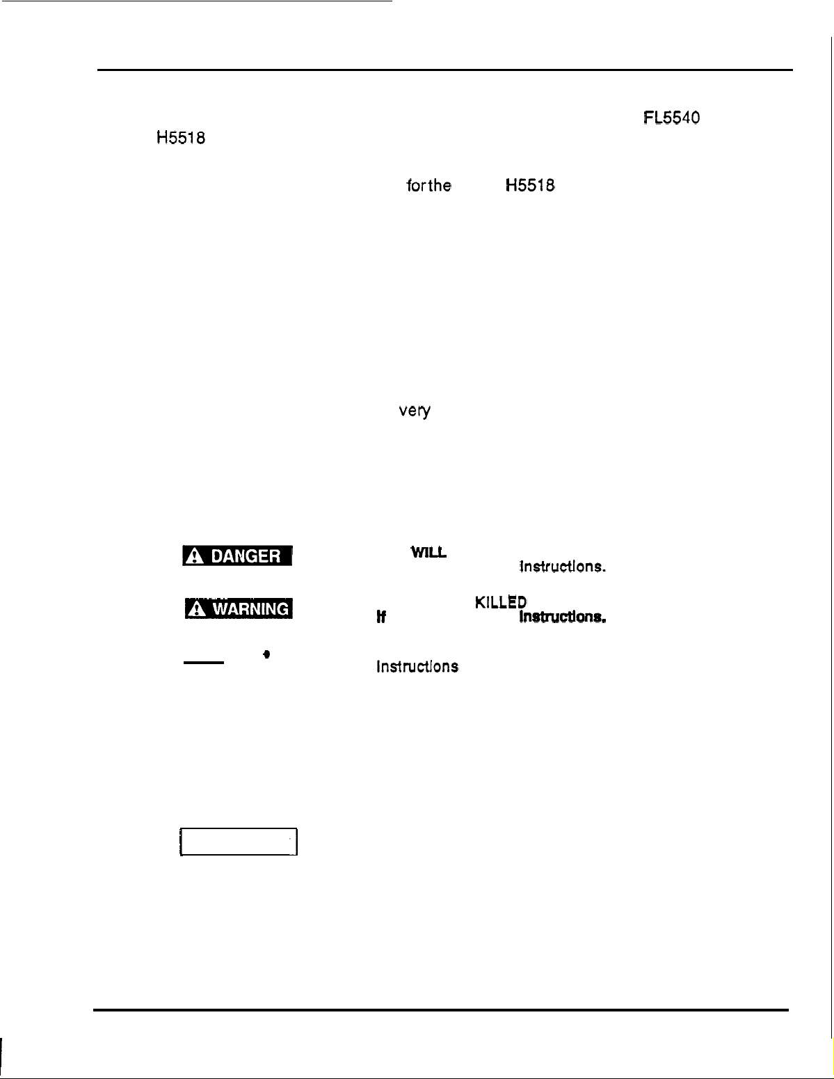
Safety Messages
Your safety and the safety of others are very important. We have provided important safety
messages in this manual ond on the front loader. Please read these messages carefully.
A
safety message alerts you to potential hazards that could hurt you or others. Each safety
message is proceded by
WARNING, CAUTION.
These words mean:
a
safety alert symbol and one of three words: DANGER,
You
WILL be
If you
You
tf
0
Each message tells you what the hazard is, what can happen, and what
or reduce injury.
Damage Prevention
You will also see other important messages that are proceded by the word NOTICE.
This word means:
I
NOTICE
Messages.
.I
You
lnstnrctlons
Your equipment
CAN
you
CAN
don’t
don’t
damaged
Using this product
Read
to
and understand this Operator’s Manual
do
so
could result in personal injury
for
a
purpose not intended can cause injury
or
equipment damage.
KILLED
follow
be
KILLED
follow
be HURT
if
you
don’t follow instructions.
before
or
SERIOUSLY
Instructlons.
or
SERIOUSLY
Instructlons.
If you
don’t
follow
you
or
other property can
or
operating
the
front
HURT
HURT
can
do
be
property damage.
loader;
to avoid
failure
If a problem should arise, or
-
authorized Honda Multi
purpose Tractor dealer.
if
you have any questions about your front loader, consult an
1
Page 4
CONTENTS
TOPIC
1 .GENERAL
2 . INTRODUCTION
Front loader safety
Maintenance safety
Safety label locations
3
.
PACKAGING INVENTORY
4 . TRACTOR PREPARATION
5 . LOADER SPECIFICATIONS
6
.
ASSEMBLY INFORMATION
Sub-frame installation/removal
Front loader assembly
Operational checks
......................
......................
...................
.................
.................
................
...............
.................
.........
.........
......
.........
.........
.........
....
1
.......
.............
............
.............
............
.........
.........
.........
.........
.........
.........
.........
5..
PAGE
1
3
4
7
8
9
10
11
12
13
19
25
7 . OPERATING INSTRUCTIONS
8
.
LOADER REMOVAL
Storage
9
.
LOADER INSTALLATION
10 .TROUBLESHOOTING
11 . LUBRICATION and MAINTENANCE
Lubrication and maintenance chart.
12 . PARTS
13 . WARRANTY SERVICE
.......................
.........................
..................
................
...............
............
..............
.........
........
.........
.........
.........
........
.........
.........
.........
..........
.........
27
-31
35
37
41
43
44
45
.
51
.
2
Page 5
~
INTRODUCTION
INTRODUCTION
The purpose of this manual is to instruct you in maintaining and operating your HTA
Front Loader. Read it carefully; it furnishes information and instructions that will help you
of
achieve years
to unknown and varying conditions. However, through experience and these instructions, you
should be able to develop operating procedures suitable to your particular situation.
"
Right" and "Left
machine will travel when in use.
The illustrations and data used in this manual are current at time of printing, but due to possible
-
line production changes, your machine may vary slightly in detail. Extra equipment that may
in
be shown
redesign and change the machine as may be necessary without notification.
on
dependable performance. Some information may be general in nature due
"
as
used throughout this manual are determined by facing the direction the
the machine
is
optional at extra cost. The manufacturer reserves the right to
NOTE: Illustrations used in this manual may not show
to
ensure safe operation of tractorAoader. Referto Safety Section of this manual and the Tractor
Owner's Manual for information concerning safety equipment. Consult your dealer for further
information.
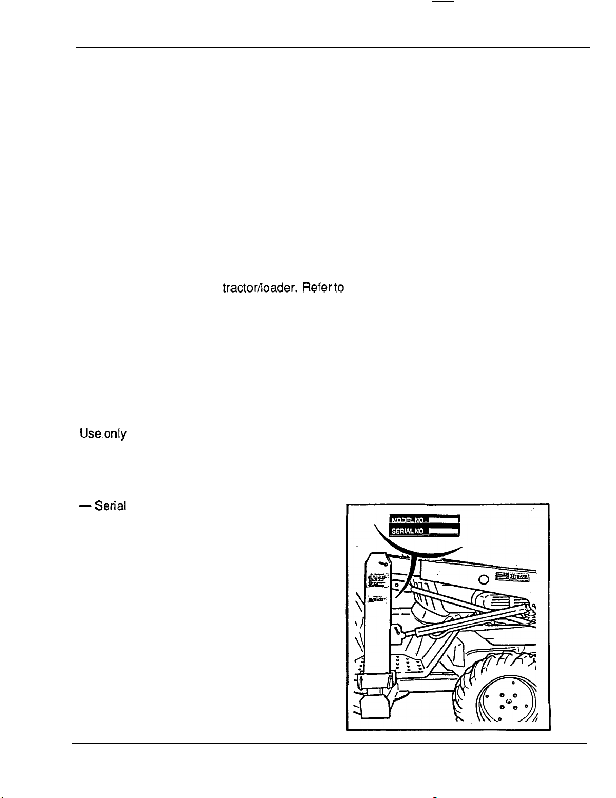
SERIAL NUMBER and LOCATION
The serial number is important information about the machine, and
it before obtaining the correct replacement parts. The serial number is located on the right side
mast as shown.
REPLACEMENT PARTS
Use.only Genuine Honda Replacement parts to repair this machine. Honda replacement parts
are available from your Honda Multi
service, always remember to give the dealer the following information:
-
Correct part description or part number.
-
Model number
-Serial number of your machine.
of
your machine.
-
purpose Tractor Dealer. To obtain prompt, efficient
all
safety equipment that is recommended
it
may be necessary to know
3
Page 6

FRONT
LOADER
SAFETY
FRONT LOADER SAFETY
Operating the tractor
and
the safety of others. Know these requirements before you operate the tractor
and
front loader requires
special
efforts
on
your
part
to ensure your safety
loader.
SAFE
OPERATING RULES
Severe personal injury
(
pages
Always make pre
accident
To avoid severe personal injury
25
thru
30
or
equipment damage.
All parts, especially guards and shields, should be
place.
Be sure all nuts, bolts and screws are tight.
Do
not remove any guards, warning labels, shields or safety devices; they are installed for your
saf.ety.
The tractor
-
you are also wearing the seat belt.
-
the
roll
ROPS
is securely attached and has not been modified
or
equipment damage may result
)
are not followed.
-
operation checks ( page
or
equipment damage, observe the following precautions.
over protective structure
if
the operating instructions on
25
)
before you start the engine. You may prevent an
in
good condition, and securely fastened in
(ROPS)
will only protect you from injury
or
structurally damaged.
if;
or
front
Know how to stop the engine quickly. Thoroughly understand operation of all controls.
or
Never permit anyone to operate the tractor
The tractor
loader.
Keep children and pets at a safe distance during operation.
Never allow anyone to get under the front loader bucket
bucket is raised or tractor engine
Always wear sturdy shoes
tractor
Be alert.
or
drugs.
Work with the equipment only in daylight or good artificial light.
Watch out for and avoid rocks, roots, holes and other objects.
If
you hit an object, stop and inspect for damage; repair any damage before you operate the
equipment again.
Replace damaged,
is
an operator
or
the front loader.
Do
not operate the front.loader when you are tired,
worn
only
vehicle,
or
boots
or broken parts immediately.
do
is
running.
and avoid wearing bulky
front loader without proper instructions.
not allow passengers to ride on the tractor.or front
or
reach through the
or
loose clothing while operating the
ill
or
under the influence
lift
arms when the
of
alcohol
The exhaust contains poisonous carbon monoxide gas that can cause
if
and may lead to death,
the front loader
is
operated in an enclosed place.
loss
of consciousness
Page 7

The use of heavy equipment andor pulling or lifting excessive loads may adversely affect
To
avoid
loss
vehicle stability or control.
-
Use only recommended tractor hitch attachment points.
-
Limit loads to those within tractor and front loader limitations as stated in this manual and in the
tractor owner’s manual.
-
Be extra careful when turning or backing up, and when on uneven terrain.
-
Use counterweights as indicated in this manual and the tractor’s owner’s manual.
Before installing or using the front loader, carefully read all instructions and precautions.
OPERATION
Be sure to fasten the seat belt whenever driving the tractor with the Roll Over Protection
Structure (ROPS) attached. Use of either device (seat belt or ROPS) without the other will
a
increase the chance of injury in
rollover.
of control that can result in severe personal injury:
Adjust the seat belt
Be sure that the main transmission lever is in
(PTO) levers are
Operate the tractor and
operating characteristics and controls.
Do
not operate the tractor or front loader until you are sure the area in front and behind
of people and pets.
Sudden stops
Be especially careful during sharp turns and when front loader bucket has material in it.
Carry the front loader
and front vision.
Using the front loader for handling large objects such
recommended.
equipment damage or severe personal injury,
This tractor utilizes Four Wheel Steering
tractors and will affect front loader operation. Practice use of the front loader
so
it is snug.
“Neutral” and the front and rear Power Take
in
the
“Off‘
position before starting the engine.
the front loader at slow speeds until you become familiar with all
of
the tractor or front loader during operation could cause the tractor to overturn.
arms at a
These items can easily shift or roll down the front loader arms causing
low
position during transport. This will enhance vehicle stability
as
round hay bales, logs or oil drums is not
(4WS). The feel of 4WS
is
slightly different from other
in
a
wide safe area.
of
is
Off
the
clear
Page 8

FRONT
LOADER
SAFETY
Never operate the tractor or front loader when visibility
weather; your ability to see obstacles will become impaired.
Avoid loose
overturn.
The front loader is intended for relatively flat terrain
Avoid overhead wires and obstacles when the front loader is in the raised position. Contacting
electric wires can cause electrocution.
Allow for the added length of the front loader attachment when making turns to prevent striking
people or objects.
When operating the front loader on a slope, always drive up and down the face of the grade.
Turning or driving across the face of the slope may cause the tractor to overturn.
Operate the front loader arms gradually by
movements that could cause damage to the front loader
Use added caution when working with shifting or loose loads
cause vehicle instability
To avoid
when operating the front loader on sloping or uneven surfaces.
fill,
loss
rocks and holes. They may cause vehicle instability or cause the vehicle to
"
feathering" the loader controls to prevent abrupt
or
fall out of the bucket and cause personal injury.
of control
or
overturning, always reduce speed and exercise extreme caution
is
diminished by darkness
useage.
and
tractor.
in
the.loader bucket. It could
or
by bad
Operate loader controls only from the operator's seat to prevent possible severe personal injury.
Attempting to change gears while operating the front loader on a slope may adversely affect
vehicle stability and control and severe personal injury could result.
Do
not back down,
To
avoid
loss
Do
not operate the front loader near the edge of a ditch or an embankment. Slipping off the
edge could lead to severe personal injury or equipment damage.
When descending a slope, disengaging the clutch or shifting into neutral can cause
control that may result in severe personal injury.
Be sure to follow instructions below whenever applying the tractor differential lock during front
loader use.
-
Do
not apply the tractor differential lock while turning, use the differential
in
a
straight line.
-
Never apply the differential lock on paved surfaces.
TO
avoid injury to yourself and others; before leaving the front loader unattended,
-park on level ground and lock the parking brake.
of
control
or
rapidly accelerate up a sloping surface.
or
overturning, do not stop or turn on sloping surfaces.
loss
lock
only while driving
ALWAYS;
of
6
-lower the front bucket flat to the ground.
-
disengage the front loader drive system.
-
stop the engine and remove the key.
If
you find
the wheels.
it
necessary to park on a grade, be sure to lock the parking brake and securely block
Page 9
MAINTENANCE SAFETY
MAINTENANCE SAFETY
Maintenance of the
safety
the
and
the safety of others. Know these requirements before perfoming maintenance on
tractor or front loader.
Before performing
Before cleaning, inspecting or servicing the loader be sure to;
-lower the front loader bucket flat to the ground.
-move the front
-
stop the engine and remove the key.
Always wear safety glasses when servicing or replacing the front loader cylinder pins. Use a
brass drift and hammer. Failure to do
objects.
Operating the front loader or the tractor with damaged,
severe personal injury.
Before disconnecting any hydraulic lines, relieve all hydraulic pressure.
Keep hands and body from pressurized lines. Use paper ,or cardboard, not body parts, to check
for leaks. Hydraulic oil under pressure will penetrate the skin causing serious injury.
Make sure that all operating and service personnel know that in the event hydraulic fluid
penetrates the skin, it must be surgically removed within
this form
tractor
of
injury, or gangrene may result.
and
front loader requires
maintenance/inspections,read
PTO
to the off position
special
the instructions thoroughly.
so
could result in eye injuries from possible flying metal
efforts on your part to ensure your
worn,
or
broken parts may result in
a
few hours by a doctor familiar with
All nuts, bolts, and fasteners must be properly secured.
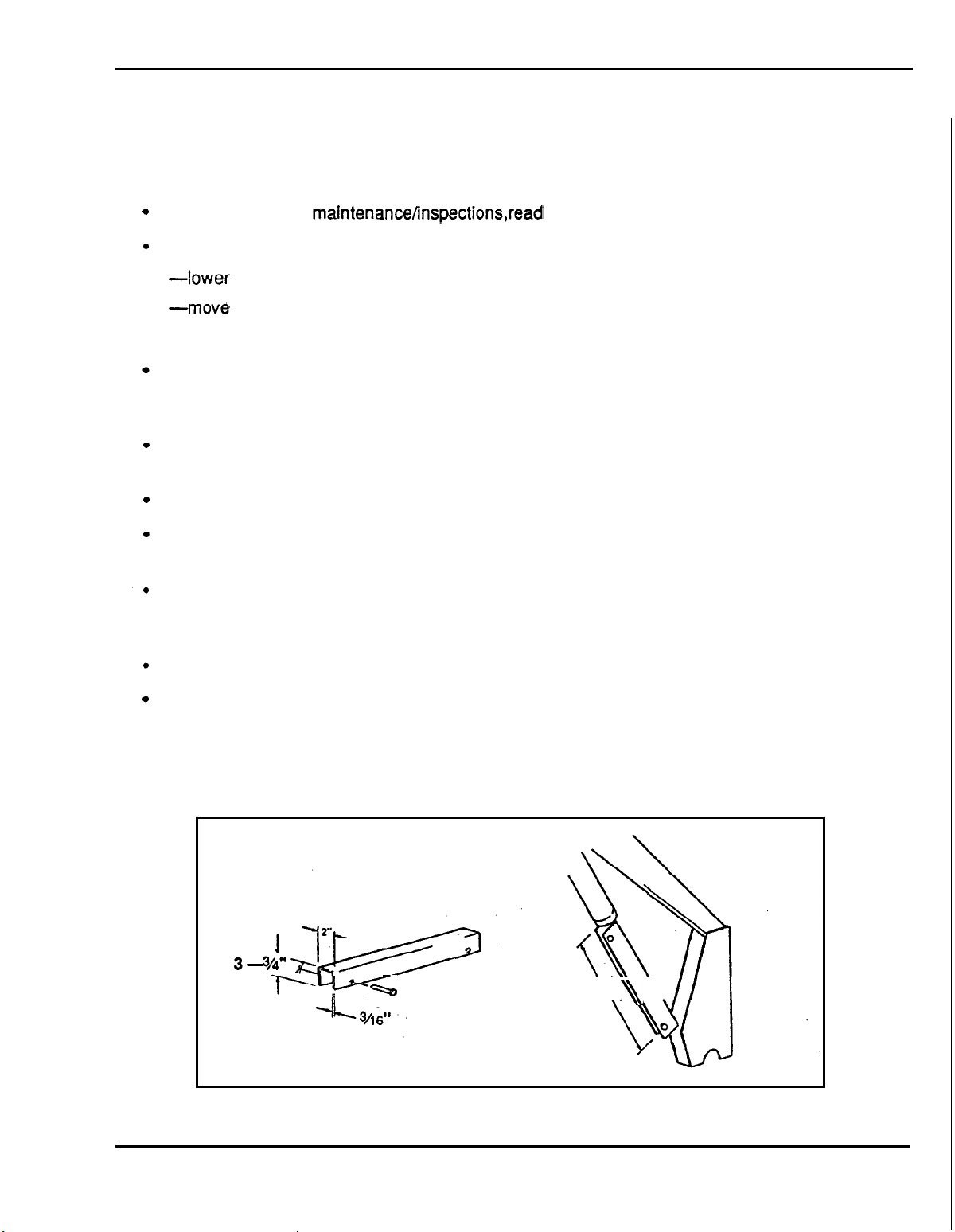
If
you must work underneath a raised loader, make sure the arms are blocked in the raised
position with a safety bar. A suitable steel safety bar can be manufactured following the
dimensions as illustrated below.
-
AS REQUIRED
.\\
\
7
Page 10
SAFETY LABEL LOCATIONS
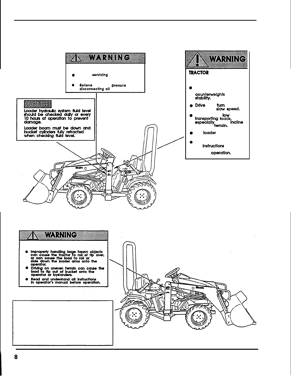
SAFETY LABEL LOCATIONS
Read these
SAFETY
LABELS
IMPROPER
SERIOUS INJURY
0
Before
lower loader to fho ground and
shut off engine.
Rolleve hydraulic
dlreonnecHng oil lines.
before
SERVICING
conlclng
you
CAN
OR
or
adjustment
pressure
operate the front loader.
CAUSE
DEATH
before
MCTOR
CAUSE SERIOUS INJURY
OR
a
Add
wheel
oounterwelghts
rtablllly.
Ddve
tractor
Place
transpomng
especially on an lncllne
or
e
Put
when
TIP-OVER
DEATH
recommended
ballast and/or
and
at
loader
rough tenaln.
Mer
parked.
Read
and understand
lnstructlons
all
operator‘s manual
before
operation.
for
turn
slow
speed.
low
kads,
on ground
In
CAN
when
FALL
FROM
LOADS CAN
CAUSING SERIOUS INJURY OR DEATH
BUCKET
INFORMATION
Special loader attachments
handling large objects are
available from agricultural
suppliers.
i
for
Page 11
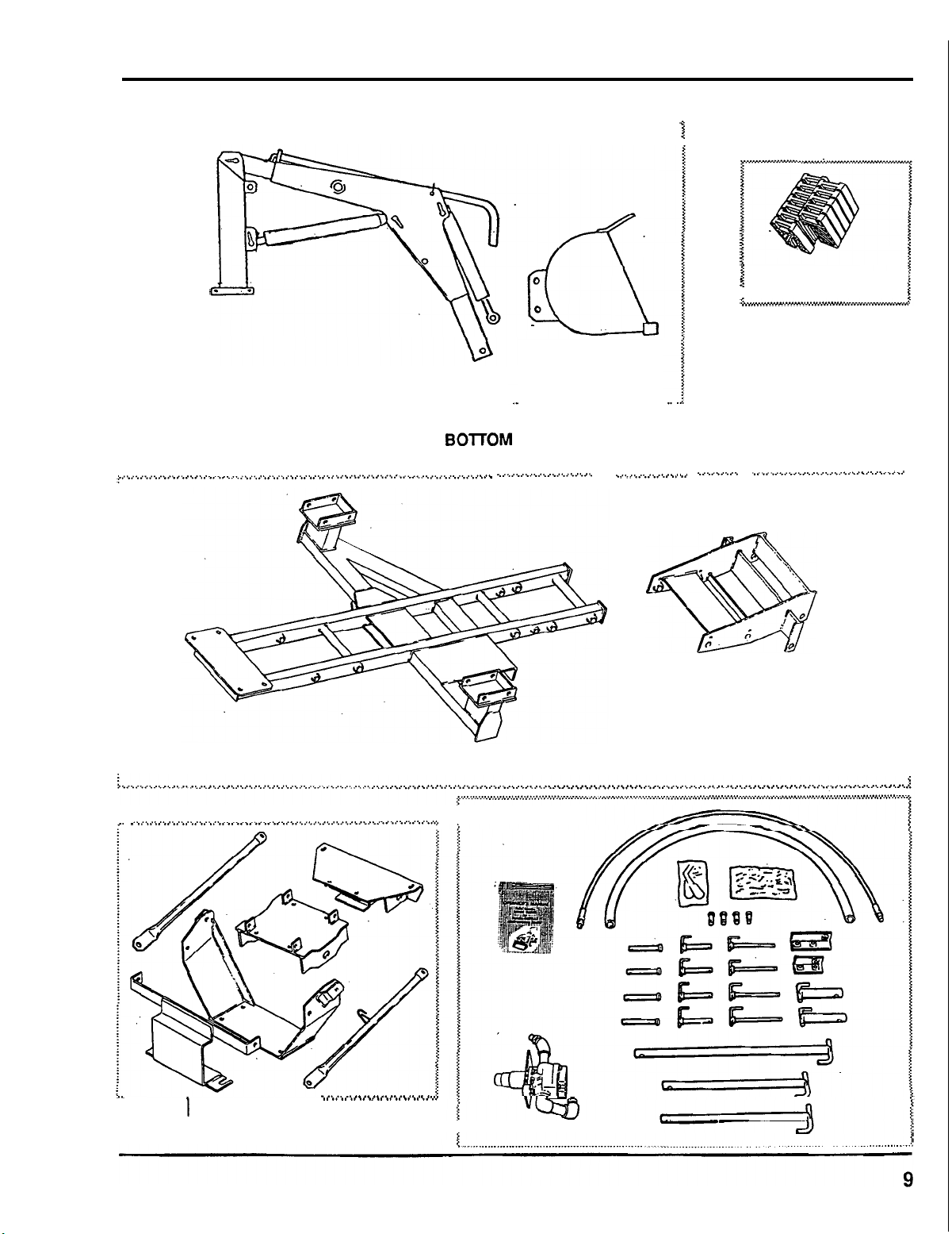
PACKAGING INVENTORY
.............................................................................................................................................
.................
................~....,..~.....................~...~..~~..............~...~....................................................,........,,..
....................................................................
SECURED
T
PACKAGING
I
O
C
RATE
BO~OM
I
INVENTORY
................................
.
..................,....CIC.......,,
........
\
.............,...,.....
12
Required
37.5
Ibs.
I
3
j
1
..
c,,..,,..,,
...
WEIGHTS
.........,.....\,.....I..........
each
...l.l\>llll.i
.
..................................................................................................
...............................................
LARGE CARTON
1
SMALL CARTON
..........................
..
Page 12

TRACTOR PREPARATION
HARDWARE BAG CONTENTS
QNT'Y DESCRIPTION
5
h"
lynchpin
2 1Omm x 30mm
2
12mm x 25mm
2
%!-13Xl
16
12 3/4xl'/4
2
2
2
#11
V2-13xl3AW
98"
7/16-14Xl
lh"
clipxpin
0
flat washer
V4"
hex
hd
hex
hd
hex
hd
capscrew
ga. machine bushing
hex
hd capscrew
hex
hd capscrew
capscrew
capscrew
-
2
2
4
6
4
4
4
2
2
2
2
1
%6"-14
7/ls"
V2"-13
l!"
1s
5/1sW-l
5/16
VIS"
5/16"-l8 13A"
54s"
#
2
nylon
hex
lockwasher
hex
flat washer
lock
washer
8
x
1
"
"
lockwasher
flatwasher
flatwasher
hose clamp
tie
nut
nut
hex
hex
hd capscrew
hd
capscrews
TRACTOR PREPARATION
This loader is not intended to be used with any other attachments mounted on tractor.
REAR COUNTER WEIGHT
m-
The use of adequate rear countenveight is required for proper loader stability.
Refer to Tractor Owner's Manual for specific recommendations on counterweighting tractor.
1-
DO NOT EXCEED THE RATING
REFER TO OWNER'S MANUAL PROVIDED WITH TRACTOR.
FOR
MAXIMUM
GROSS
VEHICLE WEIGHT.
Weight added to the rear of the tractor provides better traction and easier, more efficient loader
operation. The tractor must be counterweighted by installation of rear weights.
Additional counterweight requirements will vary with loader attachments and equipment
applications.
--Certain specific conditions may not permit safe use
or may require more carefully restricted Operation at
ROLL-OVER PROTECTION STRUCTURE (ROPS) SYSTEM
The tractor
ROPS
system must be in place and used properly to ensure adequate operator
of
loader at loader rating
the
rated load.
protection.
LOADER HYDRAULIC SYSTEM
Follow
TRACTOR
recommendations in this operator's manual for hydraulic fluid specifications.
TIRES
Selection of tires should be restricted to.tire recommendations as specified by your
Tractor owner's manual.
Ag tires are recommended when using the front loader
TIRE INFLATION
Front tires must be maintained at the maximum recommended inflation with the added weight
of loader and material.
Ag
Tire pressure
34
psi.
Rear tires must be maintained at equal pressure within the recommended tire inflation range.
24
Ag Tire pressure
psi.
10
Page 13
LOADER SPECIFICATIONS
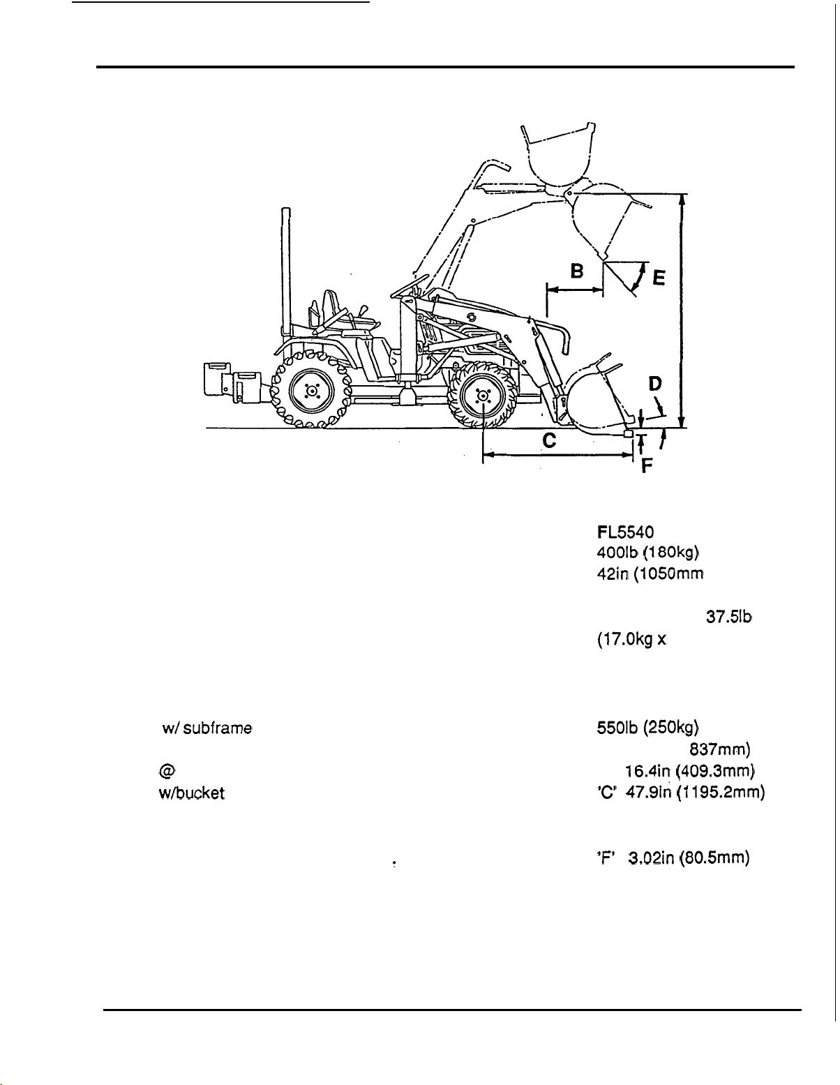
LOADER SPECIFICATIONS
A
-
-
LOADER SPECIFICATIONS
ITEM
Rated
Bucket Size (width)
Hydraulic cylinder
Counterweights
........................
Lift
Capacity
................
................
................
..................
...........................
Sub-frame
Hydraulic Pump Drive
Tractor Type
Weight w/ subframe
Maximum Lift Height
Reach @ Maximum Height.
Reach whucket
Bucket roll
Maximum Dump angle
Digging Depth Below Grade
.....................
...............
.................
................
................
............
on
back
ground
angle
............
...............
...............
.....
......
........
........
........
.........
.........
........
........
.........
H55
18 A4 only
........
........
........
........
........
........
........
FL5540
400lb
42in (1050mm
Double acting
Suit case type 37.5lb x 12
(17.0kgx 12)
Frame mount type
Front PTO coupled
-
Ag tires recommended
5501b
'A'
'B'
'C'
'D' 17'36'
'E'
'F'
(180kg)
(250kg)
72.1 in (1 837mm)
16.4in (409.3mm)
47.9in (1195.2mm)
47'31
.
3.02in (80.5mm)
)
11
Page 14
ASSEMBLY INFORMATION
GENERAL
ASSEMBLY INFORMATION
Read assembly instructions completely prior
to
installing loader
to
familiarize yourself with all
mounting and hydraulic system installation procedures.
The loader operates from its self contained hydraulic system with the pump driven from the
tractor front PTO.
A
pipe thread sealant must be used on all pipe threads.
All
hardware required for mounting loader is supplied.
Loader mount component hardware should be
left
loose until all mount components have been
installed.
Unless otherwise specified, refer to torque specification table for torque values
of
hardware
required for assembly.
Lay
out
and identify all components prior
to
installation.
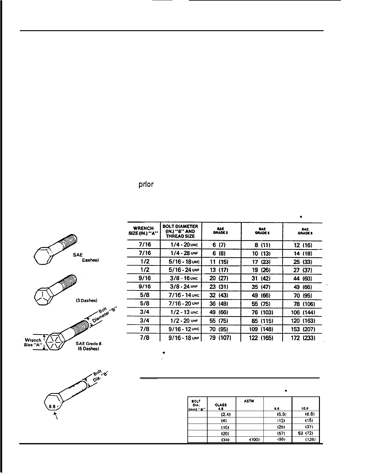
TORQUE SPECIFICATIONS
used
on Honda equipment
Pounds (Newton Meters).
AMERICAN
Bolt Head Markings
Proper torque for American fasteners
in
Recommended Torque
Foot
SA€
Grade
(No
Dashes1
SAE
Grade 5
(3
Dashes1
METRIC
4;$d
6
Numbers appearing on bolt heads
indicate ASTM class.
2
2
Use
75%
'
fasteners. Use
for lubricated fasteners;
Proper torque for metric fasteners used on Honda equipment.
Recommended Torque
of the specified torque'value for plated
85%
of the specified torque values
in
Foot Pounds (Newton Meters).
eoLT
(mm)
DIA.
5
6
8
10
12
"8"
CLASS
1.8
7.3
14.5
25
ASTY
4.0
(2.41
3
(41
(10)
(20)
(34)
74
*STY
8.8
(100)
CLASS CLASS
5.1
8.7
21.1
42
73
ASTY
9.8
(6.91
(12)
(29)
(57)
(99)
ASTY
CLASS
10.0
6.5
(8.8)
11.1 (15)
27
(37)
53
(72)
93
(126)
I
12
Page 15
FL5540
FL5540 SUB-FRAME
and
COUNTERWEIGHT
INSTALLATION/REMOVAL
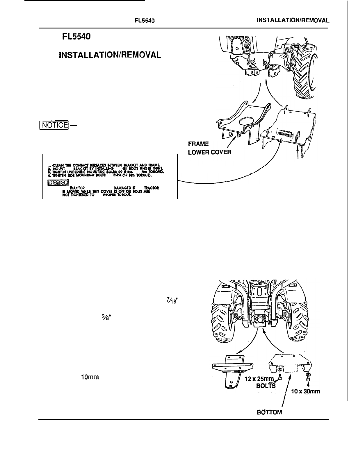
1.
Remove the existing frame lower cover
and replace with the new lower cover
using existing mounting bolts and collar
washers.
SUB-FRAME
and
COUNTERWEIGHT INSTALLATION/REMOVAL
--
1-d-
Never operate the tractor without
the lower cover.
INSTALLATION INSTRUCTIONS
1
C(M#ECO)IUCISWFACESBEIWEENBUWMrPrJllL
i
MOW
ME
BRAcILl
DY
3.
WHEN
1.
m
UNDBnDE
IIcHlEN
SIDE
LHWW
ME
IpAm
ISMOVEDWHLEMHL1COMRISOCFORWIJSAB3
NOT
lWITWE0
INSWING
MOUmNC
IOU&
FRAME
Io
ME
CAN
KHTr
29
BE
mofm
WE
Q)
WLR
29
ft-&
8-09
Hn
DAMACED
TopOK
RMCBl
09
TopouD.
F ME
h
TOpouO.
lpAcrop
lWIT.
Note: A second label is included with this
operator's manual. Install this label onto the
original
2.
frame
lower
cover.
Remove the drawbar and replace it with
the bottom bracket using the two
x
25mm hex
12
washers and two
capscrews with
hd
capscrews
10
3%"
washers.
with
x
30mm hex hd
7/16"
NEW LOWER
FRONT COVER
Torque
follows:
front
cover
and rear bracket bolts
10mm
12mm
Bolts
Bolts
29
43
ft-lbs.
ft-lbs.
(29
(60
as
Nm).
Nm).
DRAWBAR
BOirOM
..
. . -.
/
BRACKET
BOLTS
.
. .
13
Page 16
FLS540 SUB-FRAME
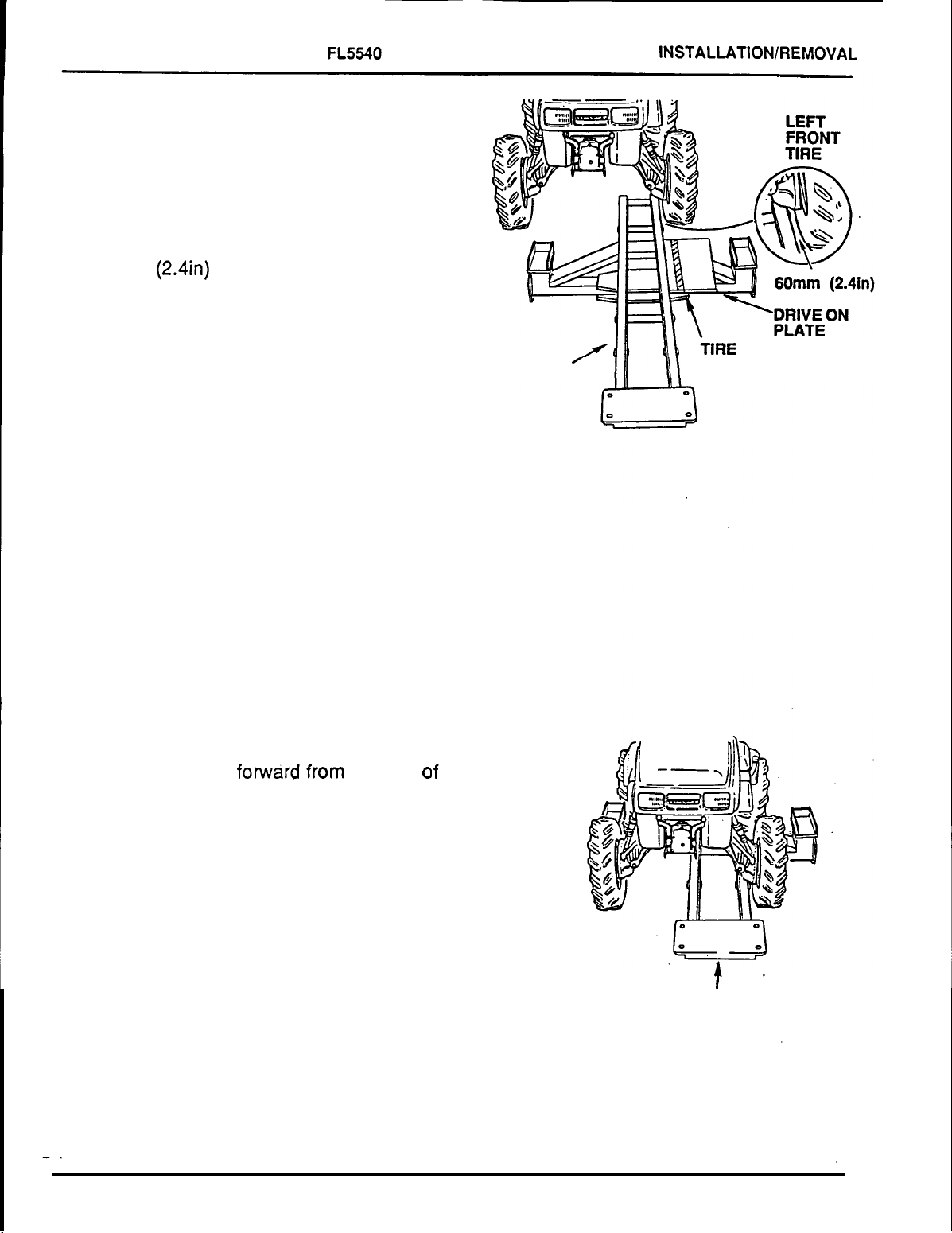
3.
Lay the sub-frame on a level, solid area.
4.
Position the tractor in line with the
sub
-
frame and tire guide on drive on plate,
allowing
60mm
inner wall
a
clearance of approximately
(2.4in) between sub-frame and the
of
the left front tire.
and
COUNTERWEIGHT INSTALLATlONlREMOVAL
5.
Drive the tractor fomvarc
,,om the rear
the sub-frame, over the drive on plate
keeping it parallel with the sub
-
frame.
o
SUB-FRAME
If
GUIDE
Page
14
SUB
-
FRAME
Page 17
FL5540 SUB-FRAME
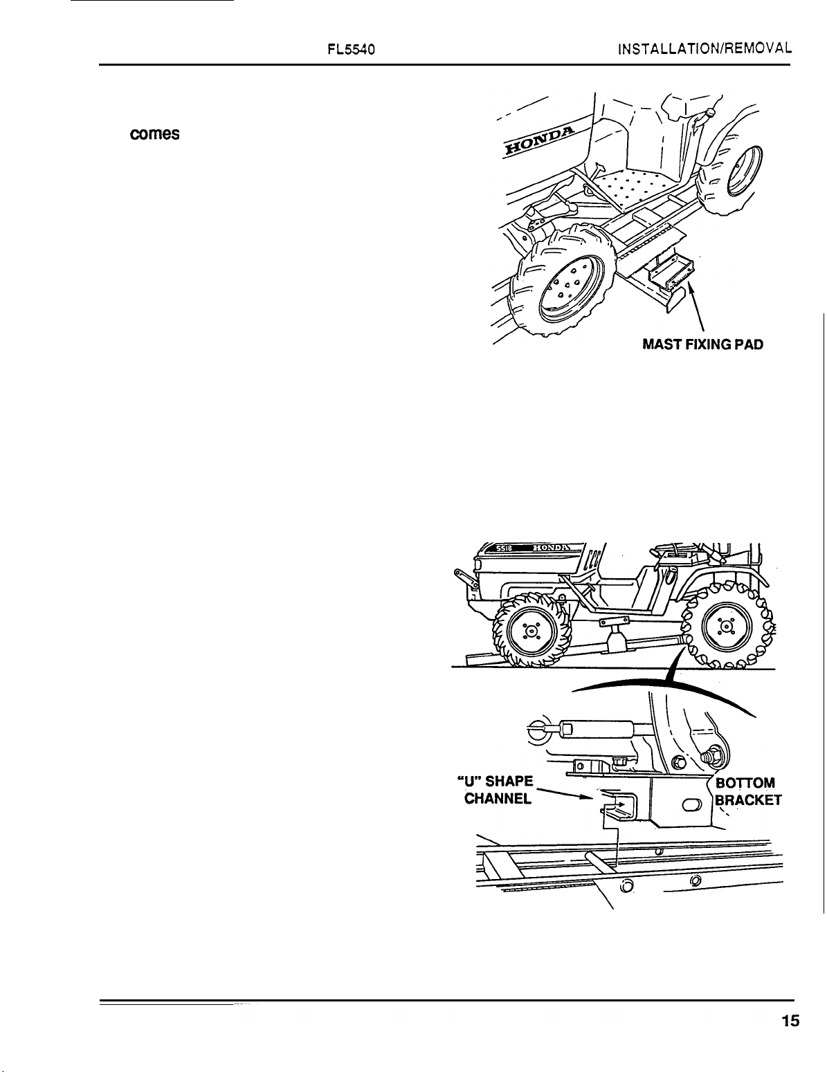
6.
Stop the tractor when the mast fixing pad
comes even with the floor board of the
tractor.
and
COUNTERWEIGHT INSTALLATION/REMOVAL
7.
Using two people, lift the sub-frame and
-
engage the pipe of sub
-
shaped channel of the bottom bracket.
U
NOTE:
Use two people to lift sub-frame.
frame into the
Page 18

FL5540
8.
SUB-FRAME
and
COUNTERWEIGHT INSTALLATION/REMOVAL
Lift the front of the sub-frame and slip it
into the channel of the lower cover. Insert
two mounting pins
inside sub
cover. Slip
-
frame through frame lower
a
(3/4 x 3.19in) from
3/4in washer over each
mounting pin and insert the clip pins
through the holes.
NOTE:
Mounting pins have a flat side that
must be pointing down.
9.
Insert two mounting pins (3/4 x 3.19inj
from inside the bottom bracket through the
sub
-
frame. Slip a washer over each pin
and retain with a clip pin as shown.
MOUNTING PIN
FLAT
SIDE
DOWN
NOTE:
Mounting pins have a flat
must be pointing down.
16
side
that
Page 19

FL5540
COUNTERWEIGHT BRACKET
INSTALLATION
10.
Place the rear counterweight bracket on
the rear
mounting holes of the bracket with those
of the sub
mounting pins in the forward holes and
one
hole. Secure with linchpins.
1
of
the sub-frame aligning the
-
frame. Insert two
x
12
inch mounting pin in rear lower
1
x
SUB-FRAME
FIXING PINS
3.5
inch
and
COUNTERWEIGHT INSTALLATlONlREMOVAL
MOUNTING PINS
-
-
LINCHPIN
COUNTERWEIGHT BRACKET
11.
Install the twelve counterweights. Insert
the
countetweight fixing pins through the
bracket and secure with linchpins.
NOTE:
procedures.
For sub-frame removal use reverse
17
Page 20

~
FL5540 SUB-FRAME and COUNTERWEIGHT INSTALLATlON/REMOVAL
Page 21

FRONT LOADER ASSEMBLY
HY
'DRAULIC PUMP MOUNTING
1.
Pump mounting plate and pump drive joint
are installed on pump. Ensure bolts and
set screw are tight.
Attach the pump brackets to the pump
mounting plate using two each %6x2 inch
5/16
"
bolts and
bracket is shorter than the
tighten the bolts at this time.
Apply a light coating of grease to tractor
front PTO at this time.
flatwashers. The right
left.
Do
not
LEFT BRACKET
RIGHT
BRACKET
FRONT LOADER ASSEMBLY
PUMP
MOUNTING
PLATE
'
-
Mount hydraulic pump to tractor by sliding
2.
splined pump drive joint onto front PTO
shaft with mounting brackets inside main
frame and attaching with four
and
5/16"
bolts
lockwashers. Tighten
5/lsx?4i inch
all
pump mounting bolts.
LOADER INSTALLATION
NOTE: The masts and main frame come
.assembled. All cylinders and hoses 'have
been attached to the frame except the
two
hoses from the hydraulic pump.
3.
Set the loader on its stands and move the
tractor centrally between the masts.
19
Page 22

FRONT
LOADER ASSEMBLY
PRESSURE
CONNECTION
4.
Remove the pipe plug from the valve body
and
SUCTION HYDRAULIC HOSE
and clean the threads and then install the
pressure hose. Remove the plastic caps
from the pump outlets.
Use
sealer on
threads and screw the other end (swivel
connector end) into the threaded pipe
fitting on the pump. Slide the suction hose
(large hose) over the pipe end at the
bottom of
mastkeservoir and pipe end on
the pump. Attach with hose clamps and
tighten securely.
HOSE CLAM
PUMP
w,
ESSURE
SUCTION HOSE
HOSE
5.
Attach the front guard on the front of the
sub
-
frame using two each
1/2x15/16
112
inch bolts, and four each
inch nuts and washers.
lhxl
inch and
Do
not tighten
bolts at this time.
AlTACHlNG LOADING MASTS
6.
Move the tractor until the masts 'are
positioned over the upright pads on the
sub
-
frame, use
two
people to lower the
masts onto the pads and insert the fixing
pins through the masts and pads. Install
clip pins to retain fixing pins.
NOTE:
Masts may have to be shaken to align
fixing pin holes.
20
FIXING
PIN.
\IF
Page 23

7.
Attach brace arms to masts with clevis
pins and clip pin.
~ ~ ~~ ~
FRONT LOADER ASSEMBLY
Tighten front guard bolts installed in step
Torque:
8.
76
ft-lb
(1
03
Nm).
Bring the two hoses along the left side
brace arm to the
on the
left
brace arm with metal loops.
left
mast. Route hoses
Ensure that the high pressure hose
(smaller diameter)
is
positioned on top of
the suction hose (large diameter).
Install the nylon tie strap to bind the two
hoses together at front corner of hoodline.
5.
9.
Install valve handles to the hydraulic
control valve mounted on the left mast.
The
"A"
handle attaches to the spool used
for loader operation and the
attaches to the
spool
for bucket operation.
"B"
handle
COTTER PIN
-
PIN
21
Page 24

FRONT LOADER ASSEMBLY
BUCKET AlTACHlNG
10.
Using the bottom holes on the bucket,
attach both sides of bucket to loader
3/4
x
3
frame. Use two each
inch pins and
clip pins.
Attach both cylinders to top holes on
bucket. Use two each
314 x 3
inch pins
and clip pins.
The loader is now ready for hydraulic fluid.
314
x
3111
PINS
HYDRAULIC FLUID SERVICING
You will need 6 1/2 quarts of a good grade
hydraulic fluid or
ATF
automatic transmission
fluid.
11.
Remove
back of
filler
left
plug
mast.
and
Fill
oil
check screw
with 4 quarts.of
on
hydraulic fluid.
.
Start tractor engine and set speed at
throttle. Engage tractor front
lift
operate loader
and bucket cylinders at
PTO
1/2
and
least five or six times to purge the system
of
air. Lower the loader to the ground.
Retract bucket cylinders by pulling back
on handle
Add
2
"
B.
1
/2 more quarts of hydraulic fluid or
until oil runs out of check hole. Replace oil
fill
plug and oil check screw.
VALVE HANDLES
NOTE:
When lowering loader,
loader handle
FLOAT.
22
DO
"A"
all the way forward into
NOT
push
I'
Page 25

~~ ~ ~~~~ ~
LOADER STAND REMOVAL
12.
Raise the loader with the loader control
until the stands clear the ground.
13.
Remove latch pin from the stands and
remove the stands.
FRONT
LOADER
ASSEMBLY
14.
Align the hole in the
bottom
of the stand
with the mounting hook at rear of
mainframe. Slide the stand over the
mounting hook and then insert the latch
pin previously removed through main
frame and through the stand. Repeat the
above steps for the other side. Lower the
loader to the ground.
Front Loader
is
ready to become operational.
MOUNTING
=I
HOOK
23
Page 26

FRONT
NOTES
LOADER
ASSEMBLY
24
Page 27

OPERATIONAL
CHECK
OPERATIONAL
CHECK
Check all pivot points on the loader.
Lubricate as necessary.
(See lubrication chart.) on page number
44
Check loader hydraulic fluid.
Note: Check fluid level with loader arms
down and bucket flat on the ground.
if
Remove oil check screw and see
out hole.
If
oil level is low, remove oil
(Do
not overfill)
fill
oil will run
plug and add
hydraulic fluid until it runs out of oil check hole.
Re
-
install and tighten the oil check screw and
oil fill plug. Operate the loader up and down
several times and recheck oil level.
Replenish as necessary.
Note: Bucket and
lift
cylinders should be fully
retracted when checking hydraulic fluid level:
Check
all
hydraulic hose connections to
ensure that they are not leaking.
Lubricate all pivot points that incorporate
grease fittings.
Start tractor and run engine at approximately
1200
-
1400
RPM
for initial cycling of loader.
Push PTO lever forward to
1-
the first time, cycle
-
Before using front loader for
lift
purge air from cylinder.
system can cause unexpected fall
"ON"
and bucket cylinders to
Air
in
the hydraulic
of
main
frame, causing Injury or damage to loader or
tractor.
Operate and check the loader main frame and
bucket for interference, noise, and bending of
parts.
--Before using loader, double
check:
Tractor Owner's Manual for recommended
tire,pressure
That all bolts and hoses have been tight
ened and that all tools have been removed
from tractor and loader.
Counterweights are Installed and correct.
UP
START
Ensure tractor meets
PROCEDURE
all
requirements in
Tractor Preparation Section.
Cycle lift and bucket cylinders with bucket
empty several times to seat
-
in cylinder
components.
Check all hydraulic hose routings to ensure
adequate clearances exist between hoses
and adjacent components.
1
-
-
The tractorlfront loader
should only be operated with all safety
-
equipment properly Installed.
-
Operate loader from
,tractor seat only. Engine will not run with
engaged unless operator's seat
Is
occupied.
the
BTO
Check front loader hydraulic fluid level. Refer
to front loader operator's manual.
25
Page 28

~_____
OPERATIONAL
OPERATING
NOTICE-Do not use the bucket for pushing
down material with bucket cylinders partially
extended. Cylinder and rod may be
damaged.
Do
not
extend bucket cylinders) during
backfillinghackgrading operation. Cylinder
and rod may be damaged.
Position vehicles
as possible and in such a direction
minimize the amount
required to dump.
Do
not use the spill guard
it will deform and become damaged.
Keep the unit clean and perform regular
service. Observe safety instructions
whenever cleaning,
We urge you
CHECK
TIPS
..
tip bucket cutting edge down (fully
to
be loaded as near the pile
as
to
of
tractor turning
to
push objects as
setvicing,or lubricating.
to
follow
this advice:
6.
When lowering a heavy load, ease
downward slowly. Never drop a loaded
bucket and “catch” hydraulically.
it
Stopping a load after
downward momentum places undue
strain on the unit and may cause damage
to the loader or tractor.
m
-
A-
hydraullc lines, relieve all
Escaping hydraulic oil under pressure can
have sufficient force to penetrate the skin
causing serious personal injury.
escaplng hydraulic oil, consult a physlcian
Immediately.
I-
the hydraulic fittings or hoses are leaking or
damaged.
main frame to drop suddenly, causing damage
to the tractor or loader
-
Before disconnecting
hydraullc pressure.
-
Do
not operate the loader
A
sudden line burst can cause the
or
injury
has gained
If
Injured by
to
personnel.
it
if
1.
Read and understand this manual as
as the tractor owner’s manual.
2.
Remember and observe the Safety
Precautions
this manual, the tractor manual and on the
loader itself.
3.
Use good common sense in the everyday
operation of this unit, Safety instructions
can never be all inclusive. You are
responsible for watching out for, and
avoiding, unsafe conditions.
4.
Never exceed the limits of
machinery.
so
safely
5.
Don’t hurry the learning process or take
the unit for granted. Ease
become familiar with your new loader and
tractor.
brought
to your attention in
a
If
its ability to do a job or to do
is
in question-Don’t try it.
into
piece of
it
well
and
BEFORE OPERATING, LUBRICATE ALL
MOVING PARTS. (Refer to lubrication section)
COLD
To assure smooth operation in cold weather,
allow the tractor to warm up. Slowly cycle the
loader and bucket several times to warm the
fluid in the hydraulic system. The loader may
operate erratically until the hydraulic fluid has
warmed to operating temperatures.
WEATHER OPERATION
26
Page 29

OPERATING INSTRUCTIONS
OPERATING INSTRUCTIONS
Main,
acting type (both push and pull under
hydraulic power). This means that the loader
can be forced down as well as up. It means
that the bucket can be tilted down or up with
hydraulic pressure.
HYDRAULIC CONTROL VALVE
Your loader control valve has two handles.
The right handle operates the
(the loader) and has a float position. The
handle operates the bucket cylinders. Both
handles
position when released.
LEFT HANDLE
A
B
c
lift
-
-
-
and bucket cylinders are double
lift
cylinders
will
return to neutral except from float
RIGHT
-
BUCKET
Bucket Dump
Neutral
Bucket Back
HANDLE - LOADER
A
-
Float
Position
Loader Down
Neutral
Loader Up
C
D
B
-
-
-
left
LOADER
A
POSITION
way forward (this
--Right handle pushed all the
is
float position). Handle will
stay until pulled back.
POSITION
forward, bucket
POSITION
POSITION
bucket
B -Right handle pushed half way
will
lower.
C
-
Neutral position.
D
--Right handle pulled back,
will
raise.
Note: In float position there is no hydraulic
pressure going
loader frame
to the ground by gravity. When the bucket
on the ground (and the valve
the bucket will
to
is
up
follow
the
lift
cylinders.
off
the ground, it will lower
is
still in float)
the shape
of
the ground
If
the
is
even when the tractor is moving. This allows
hydraulic
oil
to
flow
back and forth in the
hydraulic system as the loader is raised and
lowered by the ground contour.
-Do
not
allow
bucket
Into ground when tractor is moving forward in
float. The bucket bottom should be level with
the ground or slightly rolled back.
lip
to
dig
HANDLE USE
BUCKET
POSITION
A -Left handle pushed forward,
bucket will dump.
POSITION
POSITION
B
-
Neutral position.
C
-
Left handle pulled back,
bucket will roll back.
NOTE: The float position is most commonly
used with attachments in snow removal.
Tractor should be run at slow ground speed
and the
material loose and
lift
and bucket cylinders used to work
fill
the bucket.
27
Page 30

OPERATING INSTRUCTIONS
CONTROLLED RATE
of
LOADER FUNCTIONS
By feathering (slightly moving) the control
levers, precise operational speeds can be
obtained. This action controls the position
of
the valve spools in the control valve and
regulates flow of oil fromho cylinders.
is
important to utilize this operational
It
SCRAPING
When scraping, the "float" position should be
utilized to maintain the bucket firmly on the
ground and at the same time allow the bucket
to follow ground contours.
"B
..
..
..
'
'
LE^
.
..
"ANOLE
A
-
8
-
C
-
A
-
BUCKET
Bucket Dump
Neutral
Bucket Back
'.
CB
*:
RIG'HT
HANDLE - LOADER
A
-
Float
B
-
Loader
C
-
Neutral
D
-
Loader
Position
Down
Up
The bucket should be positioned level to the
ground during
BACKFILLING/BACKGRADING
"
scraping" operations.
When "backfilling" or "backgrading", position
the bucket
so
it is level on the ground. Do not
dump material from the bucket. Additional
weight of material in bucket will assist in
"
backgrading" and increases loader efficiency
during
"
backfilling".
28
Page 31

LOADING
OPERATING INSTRUCTIONS
As
bucket begins to
roll the bucket back and raise the loader
increase
”fill”
fill
with material, gradually
to
capacity. This procedure also
results in the material being removed in layers
from the top
for
maximum loading efficiency.
.-.
..
When th
the bucket
out
le bucket is full, rais e loade
is
clear
of
material and slowly back
of
pile.
!r
so
that
For maximum loading efficiency, minimize
angle
of
turn and distance between the
loading and unloading points.
29
Page 32

OPERATING
TRANSPORTING MATERIAL
INSTRUCTIONS
Transport material to
loader bucket as
spillage and maintain maximum
tractorfloader stability.
-1-
should be in a position that will not impair
operatots vision,
Observe the following safety messages.
Bh
obstacles when loader
damage or possible death by electrocution.
During transport the loader
.
-Avoid any overhead wires or
"
unloading point" with
low
as possible to prevent
Is
raised, to avoid
.-
-
A loaded bucket should be
transported
speeds, especially
Make turns slowly and use the tractor brakes
cautiously. Afull bucket In the raised position
alters the center of gravity of the
Increases the possibility of mishaps.
In
a low position at slow ground
if
the
ground is irregular.
unit and
1-
on a loader or attachment; a
cause serious Injury.
UNLOADING
As
the tractor approaches the "unloading
point
"
, raise the loader to the height required
for
clearance
Drive slowly to position bucket above
"
unloading point", stop tractor and dump
bucket.
NOTE:
required for
As
"
dumping" clearance height increases, the
bucket position must be adjusted to maintain
a level bucket to prevent excessive spillage
of material from bucket.
-do
Do
"
not
lift
or carry personnel
slip or fall could
to
"
dump" bucket.
not raise loader higher than
dumping" clearance.
30
Page 33

LOADER REMOVAL FROM
TRACTOR
1.
Select a level, safe, and solid place for
loader removal. Lower bucket to the
ground and remove the stands from the
loader main frame.
LOADER REMOVAL FROM
TRACTOR
2.
Raise the loader until the stands can be
inserted into the loader arms.
clip
Install the
Lower the loader until the stands rest on
3.
pins into the stand ends.
the ground.
Dump the bucket until the edge of bucket
touches the ground.
31
Page 34

LOADER REMOVAL FROM TRACTOR
4.
Using the bucket to support the loader
main frame, remove loader mast fixing
pins.
Note: Use bucket operation to make fixing
pin removal easier.
5.
Remove the clip pins and mounting pins
from the masts and the front guard.
Remove the hydraulic hoses from the
brace loops.
Remove the brace arms.
6.
Roll
back the bucket to detach loader from
sub
-
frame. Operate the bucket
slowly
avoid loader to tractor interference.
left
to
32
~
Page 35

7.
Put the tractor in reverse and drive it back
2
feet. Remove the front guard from
sub
-
frame.
LOADER REMOVAL
FROM
TRACTOR
8.
Remove the hydraulic pump by removing
the four bolts holding the mounting
brackets to the tractor frame.
PTO
Remove the pump from the
NOTE:
Loader
For sub
Do
not disconnect hoses.
is
now parked and ready for storage.
-
frame removal
see
pages
shaft.
13
thru
17.
33
Page 36

LOADER REMOVAL FROM
NOTES:
TRACTOR
34
Page 37

STORAGE
STORAGE
END
OF
SEASON
1.
If
loader is to be dismounted from the
tractor during storage, make sure parking
area is on hard, level ground.
2.
Store in
Note:
All
retracted position.
3.
Thoroughly clean the loader of all
accumulated dirt and grease.
4.
Completely lubricate the loader as
specified in lubrication section of manual.
5.
Using an oil soaked cloth, lubricate
hydraulic cylinder rods to protect them
from rust and corrosion.
6.
Repaint any areas where paint is worn or
damaged.
7.
Wear areas on buckets or other
attachmentsshould
to prevent rust or corrosion.
8.
Replace any safety or warning labels that
are not readable due
1-
on or around
a
dry,
sheltered area,
hydraulic cylinders should
be
coated with grease
to
wear or damage.
-
Do
not allow children to
the
tractor or loader.
if
possible.
be
in the
all
play
PROCEDURES
BEGINNING
1.
Review safety precautions and operation
sections of manual.
2.
Thoroughly clean loader of all
accumulated
3.
If
removed from tractor for storage,
remount loader per
section of this manual.
4.
Completely lubricate the loader per the
lubrication section of this manual. Make
sure
5.
Clean with solvent any exposed surfaces
which had been coated with grease. Wipe
dry
an oil soaked cloth.
6.
Tighten any bolts that may have been
loosened and make sure all pins are in
place.
7.
Start tractor and operate loader to make
sure it is operating properly and
are properly connected.
8.
Check hydraulic fluid level in loader mast
and
in this manual.
9.
Make sure, hydraulic hoses, lines and
fittings are in good shape and are not
leaking. Repair or replace as, needed.
OF
SEASON
dirt
and grease.
“Loader
all
fittings are taking grease properly.
Installation”
with a clean cloth, then lubricate with
all
fill
if
required. Use oil recommended
hoses
35
Page 38

STORAGE
NOTES
36
Page 39

LOADER INSTALLATION
LOADER INSTALLATION
I
NOTE: Install sub-frame and weights (Page
13
-
17).
-
The sub
assembled.
frame, masts and main frame are
All
cylinders and hoses are
attached to the loader frame and hydraulic
pump.
1.
Move the tractor centrally between the
masts.
2.
Mount hydraulic pump to tractor by sliding
splined pump drive joint onto front PTO
shaft with mounting brackets inside main
frame and attaching with four
inch
bolts.
5/16
x
7/8
3.
Attach the front guard on the front of the
-
frame using two each 1/2 x 1 inch and
sub
1/2
x
1 5/16 inch bolts, and four each 1/2
inch nuts and washers. Tighten bolts and
nuts.
Torque: 76 ft
-
lb (1
03
Nm)
37
Page 40

LOADER INSTALLATION
AlTACHlNG
4.
Move the tractor until the masts are.
LOADER
MASTS
positioned in line with upright pads on the
sub
-
frame, use two people and the bucket
to lower and guide the masts onto the
pads.
5.
Use bucket movement to shake masts to
align pin holes. Insert the fixing pins
through the masts and pads. Install clip
pins through holes.
6.
Attach brace arms to mast and front guard
as shown with clevis pins and clips.
NOTE: Route hydraulic hoses along left
brace arm through hose holder
loops.
Ensure high pressure hose (smaller
two)
is
positioned on top of larger suction
hose.
of
Page 41

LOADER STAND REMOVAL
7.
Raise the loader with the loader control
until the stands clear the ground.
8.
Remove fixing pin
from the stands and
remove the stands.
LOADER INSTALLATION
9.
Align the hole in the bottom of the stand
with the mounting
ho.ok at rear of
mainframe. Slide the stand over the
mounting hook and then insert the fixing
pin previously removed through main
frame and through the stand. Repeat the
above steps for the other side. Lower the
loader
Front Loader
(Page
25)
to
the ground.
is
ready for operational check.
Page 42

I
40
Page 43

TROUBLE
SHOOTING
TROUBLE
SYSTEM DOES NOT WORK AT ALL
PTO
in
'OFF'
No oil
Check system for leaks.
Oil low
proper level. Check system for leaks.
Restriction
could be collapsing to cut off oil supply.
Replace line.
Air leaks
hose clamps or replace hose.
Dirt
needed, drain and flush hydraulic system.
Badly worn pump
causing pump wear.
Oil leak
or replace defective lines.
Hoses attached improperly
properly and tighten securely.
in
in
in
pump - Clean and repair pump.
in
position
system
reservoir - Check and
in
system - Oil suction line
in
pump suction line - Check
pressure lines -Tighten fittings
SHOOTING
-
Put
to
'ON'.
-
Fill to proper level.
-
Check for problems
-
fill
to
If
Attach
SYSTEM
Cold oil - Allow to warm up before
operating.
Oil viscosity too heavy
specifications on proper oil.
Not enough engine speed
engine speed.
Low
oil
if
could cause low
Air
system for leaks.
Badly worn pump
pump. Check for problems causing pump
wear such as contaminated oil.
Restriction
could be dirty or have inner walls that are
collapsing to cut
replace suction line.
Oil
or
replace defective lines.
RUNS
OR
WORKS SLOWLY
-
-
Increase
oil
supply - Check reservoir and add
needed. Check system for leaks that
oil.
in
system
leaks
in
-
Check suction side of
-
Repair
in
suction line - Suction line
off
oil supply. Clean or
pressure lines-Tighten fittings
or
replace
See
Control Valve Defective
SYSTEM RUNS WITH
Air
in
system - Examine suction side
system for leaks. Make sure oil level is
To
correct.
is correct and leaks fixed, use bucket and
loader cylinders
system of air.
Cold oil
start. Before operating, allow oil to warm up.
Components sticking or binding
for
dirt
Pump damaged
parts.
get air out of system after oil level
5
to
-
Oil viscosity may be too high at
or gummy deposits.
-
Check for worn or broken
-
Replace
STOPS
6
AND STARTS
times to purge the
-
of
Check
OVERHEATING
Using incorrect oil - See specifications on
proper oil.
Low oil level
Engine
Restriction
replace.
Controls stuck
position
to neutral.
running
-
OF
OIL
IN SYSTEM
-
Fill reservoir. Look for leaks.
too fast - Reduce throttle.
in
hydraulic line - Clean or
in
partially or
Free both handles
full
so
they return
open
41
Page 44

TROUBLE
SHOOTING
FOAMING
Low oil level - Fill reservoir. Look for leaks.
Water
Wrong
specifications on proper oil.
Air
leak
Tighten or replace suction line.
Kink
Worn seal around pump shaft
sealing area and replace seal. Check oil for
contamination.
PUMP MAKES NOISE
Low oil level - Fill reservoir. Check system
for leaks.
OF
OIL IN SYSTEM
in
oil - Drain and replace oil.
kind
in
in
oil suction line - Replace oil line.
of oil being used
line from reservoir to
-
pump
-
See
-
Clean
LOAD DROPS WITH CONTROL VALVE IN
NEUTRAL POSITION
Leaking or broken oil lines from control
to
valves
Tighten or replace lines.
Oil leaking past cylinder packing or
“0”
rings
caused
system and determine source of dirt.
Oil leaking past control valve
replace valve. Wear may be caused by
contamination. Clean system and determine
source of dirt.
CONTROL VALVE STICKS
Valve broken or scored internally
Replace valve.
cylinder
-
Replace worn parts.
by
contamination, clean hydraulic
-
Check for leaks.
If
-
Clean or
OR
WORKS HARD
wear is
-
-
Oil viscosity too high
on proper
Cold oil - Allow oil
operating.
Suction line plugged or pinched
replace
Reservoir air vent plugged
plug, flush, and clean air vent.
in
Air
Check system for leaks. Check pump shaft
seal.
.Worn or scored
-
Replace pump.
PUMP LEAKS OIL
Damaged
Replace seal.
oil.
line
between reservoir and pump.
oil
-
Tighten or replace suction line.
pump
seal
around
See specifications
to
warm up before
-
Clean or
-
Remove vent
bearings or shafts
pump
shaft
-
CONTROL VALVE LEAKS OIL
Worn or damaged
rings.
to wear, clean system and look for source.
Broken valve parts
valve.
CYLINDER LEAKS OIL
Damaged cylinder bowl
cylinder. Correct cause
Rod seal leaking
contamination caused seal
source. Wear may be caused by external as
well as internal contaminants. Check piston
rod
Loose
If
contamination has caused
for
scratches
parts - Tighten parts.
“0”
rings - Replace
-
Replace parts or
of
damage.
-
Replace seal.
or
misalignment.
to
-
Replac4
wear.
“0
“0
rings
look
for
If
42
Piston rod damaged
or scratches that could cause seal damage or
allow oil leakage. Replace defective cylinder.
-
Check rod for nicks
Page 45

LUBRICATION
and
MAINTENANCE
LUBRICATION
Do
not perform any service/maintenance
and
MAINTENANCE
operations with front loader raised
ground.
Note: Lower front loader to the ground and
relieve pressure in loader hydraulic lines prior
to performing any
service/maintenance
operations on tractor or loader.
!
Bh
'
pressurized lines. Use paper or cardboard,
-
Keep hands and body from
not body parts, to check for leaks. Hydraulic
oil under pressure will penetrate the skin
causing serious injury.
Make sure that
all
operating and service
personnel know that in the event hydraulic
fluid penetrates the skin, it must be surgically
removed within
familiar
with this form
a
few hours by a doctor
of
injury, or gangrene
may result.
off
the
Inspect hydraulic hoses, connections, control
valve and cylinders for evidence of leakage
Note:
If
oil seepage past cylinder rod is
evident, look for scoring on rod.
Tractor tire inflation should be checked as
listed in tractor owner's manual to ensure tire
inflation is to specification.
Unequal inflation can result in bucket not
being level to the ground.
Front tires should be maintained at maximum
recommended inflation to maintain normal
tire profile with added loader weight and
material.
A-
m
If
the
fittings or the hoses are leaking or
damaged.
the
main frame to drop suddenly, causing
damage
-
Do
A
sudden
to
the tractor
not operate the front loader
line
burst could cause
or
loader
or
injury
personnel.
1-
-Accidental movement of
control lever or leak in the hydraulic system
could
serious Injury.
cause main frame to drop, causing
Do
not stand or walk under
raised attachment.
Note: When checking hydraulic system oil
level, the loader should be on the ground and
bucket fully retracted (all cylinders in the
retracted position). Grease all loader pivot
points as indicated on lubrication chart.
to
a
Page 46

LUBRICATION AND MAINTENANCE
LUBRICATION AND MAINTENANCE CHART
LUBRICATION AND MAINTENANCE CHART
Hydraulic oil level
Tire inflation
Loader pivot points
Hydraulic lines hoses
and connections
Lift and bucket cylinders
Mounting pins, Clip pins
-
Fixing pins
Sub
-
frame mounting
and hardware Re-torque
..........
......
......
.....
...
...
.....
Check
Check
Lubricate
Check for leakage
wear and damage
Check for seepage
Check,.
.
replace
Check
.............
.............
............
.......
.......
..............
if
missing
.............
.Daily/l 0 Hrs
.Weekly/SO Hrs
.Daily/l 0 Hrs
.Daily
.Daily/l 0 Hrs
.Daily/lO Hrs
.Weekly/50Hr
/lo
Hrs
I
44
Page 47
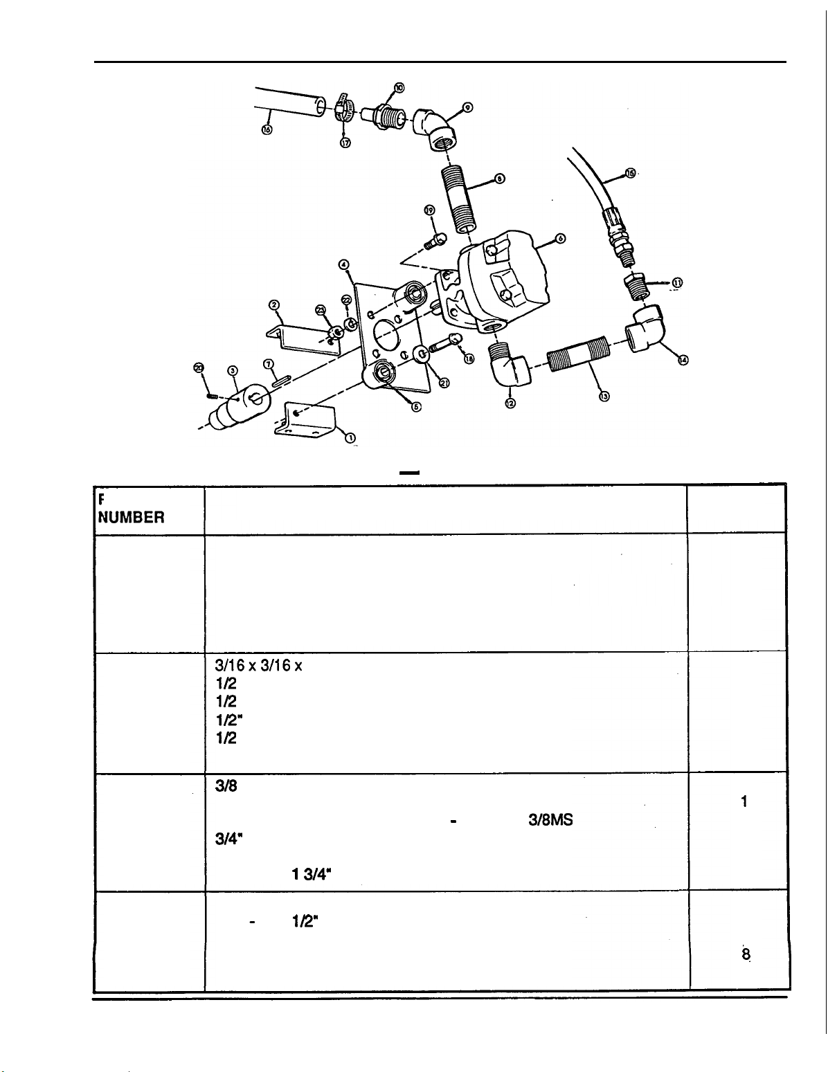
PARTS
IEFERENCE
SUMBER
1
2
3
4
5
6
7
8
9
10
11
12
13
14
15
16
17
18
REPAIR PARTS - PUMP ASSEMBLY
DESCRIPTION QUANTITY
ANGLE
ANGLE - LH
PUMP COUPLER
PUMP PLATE
RUBBER BUSHING
304
3/16x3/16x 1 KEY
1/2
1/2 x 45' PIPE ELBOW
1/2"
1/2 - 3/8 HEX REDUCER BUSHING
3/8
318 x 3" PIPE NIPPLE
3/8 90' PIPE ELBOW
3/8
3/4" SUCTION HOSE
#
16 HOSE CLAMP
5/16 - 18
-
RH
PUMP
x
2
"
PIPE NIPPLE
PIPE END
90'
ST ELBOW
X
60" HYDRAULIC HOSE 9/16 - 18 ORB X 3/8MS
X
1
3/4" HEX HEAD CAPSCREW
REQ'D
'2
1
1
1
1
1
1
1
1
1
1
1
1
1
1
48
2
2
"
19
20
21
22
23
-
18
5/16
5/16
5/16
5/16
5/16
X
-
18 X 1/2" SOCKET HEAD SETSCREW
"
FLAT WASHER
"
LOCK WASHER
-
18 HEX NUT
1
"
HEX HEAD CAPSCREW
8
1
2
8
4
45
Page 48

46
Page 49

PARTS
REPAIR PARTS
IEFERENCE
IUMBER
1
2
3
4
5
6
7
8
9
10
11
12
13
14
15
16
17
18
19
20
21
22
23
24
-
MAIN FRAME
DESCRIPTION
MAIN FRAME
-
UPRIGHT
UPRIGHT
STAND
BUCKET
PIN -A
x
5/32
#11 CLIP PIN
x
2 1/4" LYNCH PIN
3/8
x
1 1/4
LIFT CYLINDER
LIFT CYLINDER
BUCKET CYLINDER
VALVE
FEEDLINE
FEEDLINE
FEEDLINE
FEEDLINE - BOTTOM
-
9/16
1/4 X 24" HYDRAULIC HOSE 9/16 - 18 ORB
3/8
x
20
1/4 x 16" HYDRAULIC HOSE 1/4 MP x 318 MJIC
1/2"
x
1/2"
VENT PLUG
RH
-
LH
-
42
"
1" COTTER PIN
3/4" x 10ga. MACHINERY BUSHING
-
RH
-
LH
-
TOP
-
2nd
-
3rd
18 SWIVEL NUT 90' ELBOW
"
HYDRAULIC HOSE 9/16 - 18 ORB
90'
ST. ELBOW
'
x3/8.MJlC
x
3/8MS
ASSEMBLY
I
U
ANTlTY
IEQ'D
1
1
1
2
1
12
8
4
2
12
1
1
2
1
1
1
1
1
.2
4
1
8
1
1
25
26
27
28
29
30
31
32
33
34
35
36
37
38
39
1/2" PIPE END
3/8: x 90' ST. ELBOW
1/4" x 90' ST. ELBOW
#10
X
1/2"
HEX HEAD SELF-TAPPING SCREW
1/4"
-
28 UNF ST. GREASE ZERK
-
20
X
2
"
1/4
1/4" LOCK WASHER
1/4"
-
20 HEX NUT
DECAL
DECAL
DECAL
DECAL
DECAL
DECAL
DECAL
I
HEX HEAD CAPSCREW
-
VALVE OPERATION
-
HONDA
-
WARNING - IMPROPER SERVICE
-
WARNING - TRACTOR TIP OVER
-
WARNING - LOADS CAN FALL
-
NOTICE - LOADER HYDRAULIC SYSTEM
-
SERVICE INFORMATION - SPECIAL ATTACHMENTS
1
1
4
1
12
2
2
2
1
2
1
1
1
1
1
I
47
Page 50

PARTS
IEFERENCE
NUMBER
1
2
3
4
5
6
7
'8
9
10
11
12
13
14.
15
16
17
18
19
20
21
22
23
24
25
26
27
28
29
30
REPAIR PARTS - SUB-FRAME
DESCRIPTION
SUB FRAME
FRONT BRACKET
LOWER FRONT COVER, FRAME
BOTTOM BRACKET
WEIGHT BRACKET, COUNTERWEIGHTS
PUMP GUARD
BRACE ARM, RH
BRACE ARM, LH
PIN. COUNTERWEIGHT BRACKET A
PIN, COUNTERWEIGHT BRACKET B
PIN, COUNTERWEIGHT BRACKET C
PIN D. WITH FLAT (Mounting Pin)
PIN E
(Fixing
Pin)
54
x
1
114' CLEVIS PIN
711
6'
LYNCH
#11
CLIP PIN
1'114"~314"x
12
x
25mm HEX HEAD CAPSCREW
10
x
30mm HEX HEAD CAPSCREW
1/2
-
13
1/2
-
13
112.
FLATWASHER
1R'
LOCKWASHER
1/2.-
13 HEX NUT
7/16
-
711
6
"
FLAT WASHER
711
6
"
LOCKWASHER
711 6'-
3/8'
FLATWASHER
DECAL - INSTALLATION
PIN
lOga
MACHINERY BUSHING
X
1
314' HEX HEAD CAPSCREW
X
1
1M'
Hf3
HEAD CAPSCREW
14 X 1
114' HEX HEAD CAPSCREW
14
HEX NUT
QUANTITY
REQ'D
1
1
1
1
1
1
1
1
2
1
2
4
4
4
5
12
4
2
2
2
2
6
4
4
2
2
2
2
2
1
Page 51
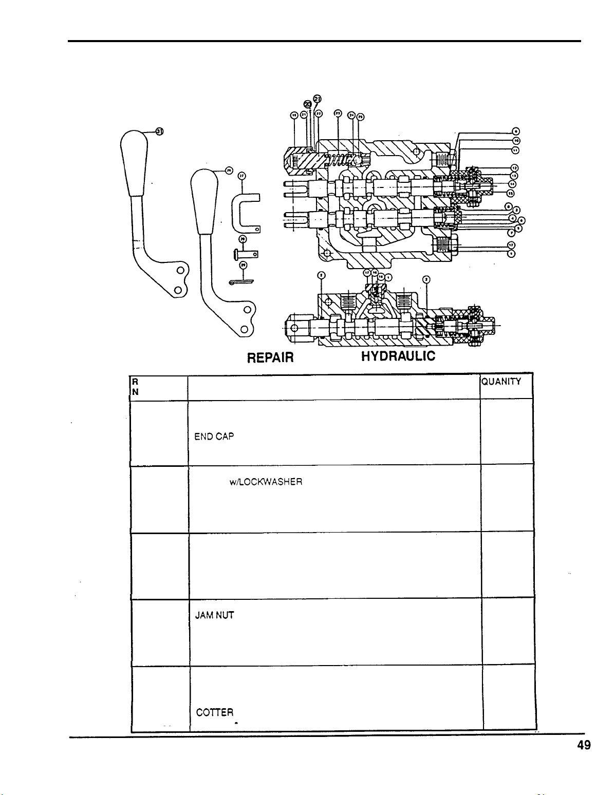
PARTS
REPAIR
EFERENCE DESCRIPTION QUANITY
UMBER REQ'D
1
O-RING
2 O-RING
3
SCREW
4
ENDCAP
5
RETURN SPRING
6
SPACER
7
WASHER
8 SCREW wROCKWASHER 2
9
SPACER
10
11
12
13
14
15
16
17
18 LOAD CHECK SPRING
19
20
21
22
23
24
25 STEEL BALL
26
27
28 PIN
29
30
DETENT SPOOL
RETURN SPRING
DETENTPLUG
DETENT SPRING
STEEL BAU
DETENT END CAP
LOAD CHECK POPPET
LOAD MCHECK PLUG
TAMPER PROOF CAP 1
JAMNUT
GASKET
ADJUSTMENT SCREW 1
RELIEF SPRING
BAU RETAINER
HANDLE, STRAIGHT
C-HOOK
COlTER PIN
HANDLE - BENT 1
.
P
A
RT
S
.
-
HYDRAKIC
VALVE
4
4
1
1
1
1
1
1
1
1
2
2
2
1
1
2
1
1
2
1
1
1
1
2
2
4
Page 52

NOTES:
Page 53

WARRANTY
SERVICE
WARRANTY SERVICE
OWNER SATISFACTION
Your satisfaction and good will are important to your dealer and to us. All Honda warranty details are
explained in the Distributor's Limited Warranty. Normally any problems concerning the product will be
handled by your dealer's service department.
to your satifaction, we suggest you take the following action:
Discuss your problem with a member of the dealership management. Often complaints can be
quickly resolved at that level.
Manager, contact the owner of the dealership or the General Manager.
If
your problem still has not been resolved to your satisfaction, contact the Power Equipment
Customer Relations Department of American Honda Motor Co., Inc.
If
the problem has already been reviewed with the Service
If
you have a warranty problem that has not been handled
American Honda Motor
Power Equipment Customer Relations Department
P.O. Box 10021
Duluth, Georgia 30136
Telephone: (770) 497
We will need the following information to assist you:
-
Your name, address, and telephone number
-
Product model and serial number
-
Date
of
purchase
-
Dealer name and address
-
Nature of problem
After reviewing all the facts involved, you will be advised of what action can be taken. Please bear in
mind that your problem will likely be resolved at the dealership, using the dealer's facilities, equipment,
and personnel,
Your purchase of a Honda product is greatly appreciated by both your dealer and American Honda Motor
Co.,lnc. We want to assist you in every way possible to assure your satisfaction with your purchase.
so
it is very important that your initial contact be with the dealer.
Co.,
-
9421
-
6400
Inc.
Page
51
Page 54

Page 55

Page 56

 Loading...