

Thank you for purchasing a Honda generator. We want to help you get the best
results from your new generator and to operate it safely. This manual contains
the information on how to do that; please read it carefully.
This owner’s manual describes the operation and maintenance of the EM650
Honda generator. All information in this publication is based on the latest
product information available at the time of printing. Honda Motor CO., Ltd.
reserves the right to make changes at any time without notice and without
incurring any obligation. No part of this publication may be reproduced without
written permission.
This manual should be considered a permanent part of the generator and
should remain with it if it is resold.
Safety Messages
Your safety and the safety of others is very important. We have provided
important safety messages in this manual and on the generator. Please read
these messages carefully.
A safety message alerts you to potential hazards that could hurt you or others.
Each safety message is preceded by a safety alert symbol A and one of
three words: DANGER, WARNING, or CAUTION.
These mean
B You WILL be KILLED or SERIOUSLY HURT if you don’t follow
instructions.
m You CAN be KILLED or SERIOUSLY HURT if you don’t follow
instructions.
m
Each message tells you what the hazard is, what can happen, and what you
can do to avoid or reduce injury.
Damage Prevention Messages
You will also see other important messages that are preceded by the word
NOTICE.
This word means:
-1 Your generator or other property could be damaged if you
don’t follow instructions.
The purpose of these messages is to help prevent damage to your generator,
other property, or the environment.
You CAN be HURT if you don’t follow instructions.
1
CONTENTS
SAFETY
COMPONENT
CONTROLS
Choke Lever
...............................................................................................
Safety
Safety
Label Locations ..................................................................
Information
..........................................................................
IDENTIFICATION .......................................................
.......................................................................................
Engine Switch
Recoil
Starter ................................................................................
...............................................................................
.................................................................................
Pilot Lamp ....................................................................................
Ground Terminal
Oil Alert
AC Circuit
System ...........................................................................
Protector
DC Terminals
DC Circuit Protector
GENERATOR USE..
AC Operation
DC Operation
Connecting the
Disconnecting the
High Altitude
PRE-OPERATION
Engine Oil
.....................................................................................
Fuel Recommendation..
STARTING/STOPPING THE ENGINE
...........................................................................
......................................................................
................................................................................
......................................................................
..........................................................................
................................................................................
................................................................................
battery cables
.....................................................
battery cables .................................................
Operation.. ..............................................................
CHECK ..............................................................
................................................................
.............................................. 24
4
.4
.6
.8
10
10
10
11
.l 1
12
.13
13
14
14
15
16
17
.17
.18
.19
.20
20
21
2
MAINTENANCE..
Maintenance
Engine Oil Change
Air Cleaner Service
Spark Plug Service
Spark Arrester
TRANSPORTING/STORAGE
TROUBLESHOOTING
WIRNING
SPECIFICATIONS..
CUSTOMER
INDEX
DIAGRAM
................................................................................................
...............................................................................
Schedule
Maintenance
SERVICE
................................................................
........................................................................
......................................................................
.......................................................................
.......................................................................
........................................................................
..........................................................................
INFORMATION
........................................................
............................................................
..........................................
25
.25
26
.27
28
.31
33
35
.37
.38
.39
40
3
SAFETY
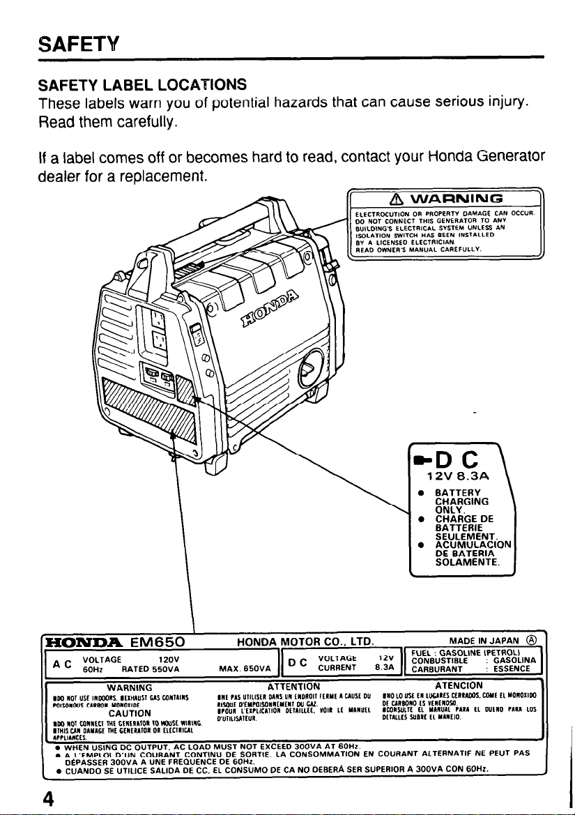
SAFETY LABEL LOCATIONS
SAFETY LABEL LOCATIONS
These labels warn you of potential hazards that can cause serious injury.
These labels warn you of potential hazards that can cause serious injury.
Read them carefully.
Read them carefully.
If a label comes off or becomes hard to read, contact your Honda Generator If a label comes off or becomes hard to read, contact your Honda Generator
dealer for a replacement. dealer for a replacement.
0 BATTERY
%K?NG
0 CHARGE DE
EATTERIE
SEULEMENT.
0 ACUMULACION
DE BATERIA
SOLAMENTE.
‘XONDA EM650
. WHEN “SlNG DC OUTPUT. AC LOAD MUST NOT EXCEED 300VA AT 60Hz.
. A L’EMPLOI D’UN COVRANT CONTIN” DE SORTIE. LA CONSOMMATION EN COURANT ALTERNATIF NE PEUT
@PASSER 300VA A UNE FREQUENCE DE 60Hz.
. CUANDO SE UTILICE SALIDA DE CC, EL CONSLJMO DE CA NO DEBERA SER SUPERIOR A 300VA CON 60th.
4
\
PAS
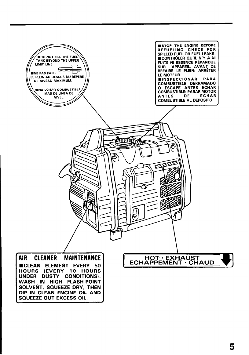
LE PLElN AU OESSUS 0” REPtRE
DE NWEA” MAXIMUM.
MAS DE LINEA DE
n STOP THE ENGINE BEFORE
REFUELING. CHECK FOR
SPILLED FUEL OR FUEL LEAKS.
ICONTR6LER QU’IL N’Y A NI
FUITE NI ESSENCE RtPANOUE
SUR L’APPAREIL. AVANT DE
REFAIRE LE PLEIN: ARRtTER
LE MOTEUR.
n INSPECCIONAR
COMBUSTIBLE DERRAMADO
0 ESCAPE ANTES ECHAR
~N~USSTIBLE: PARAR MOTOR
COMBUSTIBLE AL DEPOSITO.
DE
PARA
ECHAR
AIR CLEANER MAINTENANCE
WCLEAN ELEMENT EVERY 50
HOURS (EVERY 10 HOURS
UNDER DUSTY CONDITIONS).
WASH IN HIGH FLASH-POINT
SOLVENT, SQUEEZE DRY, THEN
DIP IN CLEAN ENGINE OIL AND
SQUEEZE OUT EXCESS OIL.
HOT-. EXHAUST
ECHAPPEMENT - CHAUD
5
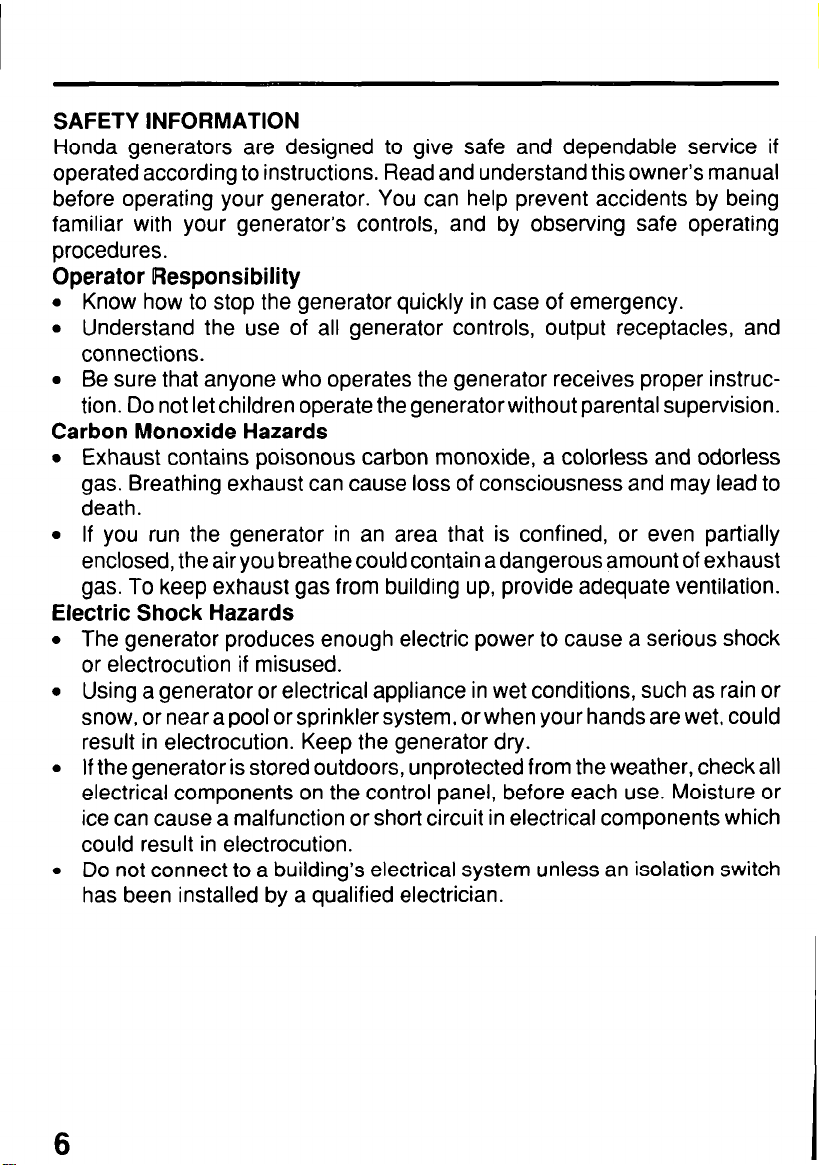
SAFETY INFORMATION
Honda generators are designed to give safe and dependable service if
operated according to instructions. Read and understand this owner’s manual
before operating your generator. You can help prevent accidents by being
familiar with your generator’s controls, and by observing safe operating
procedures.
Operator Responsibility
l Know how to stop the generator quickly in case of emergency.
l Understand the use of all generator controls, output receptacles, and
connections.
l Be sure that anyone who operates the generator receives proper instruc-
tion. Do not let children operate the generator without parental supervision.
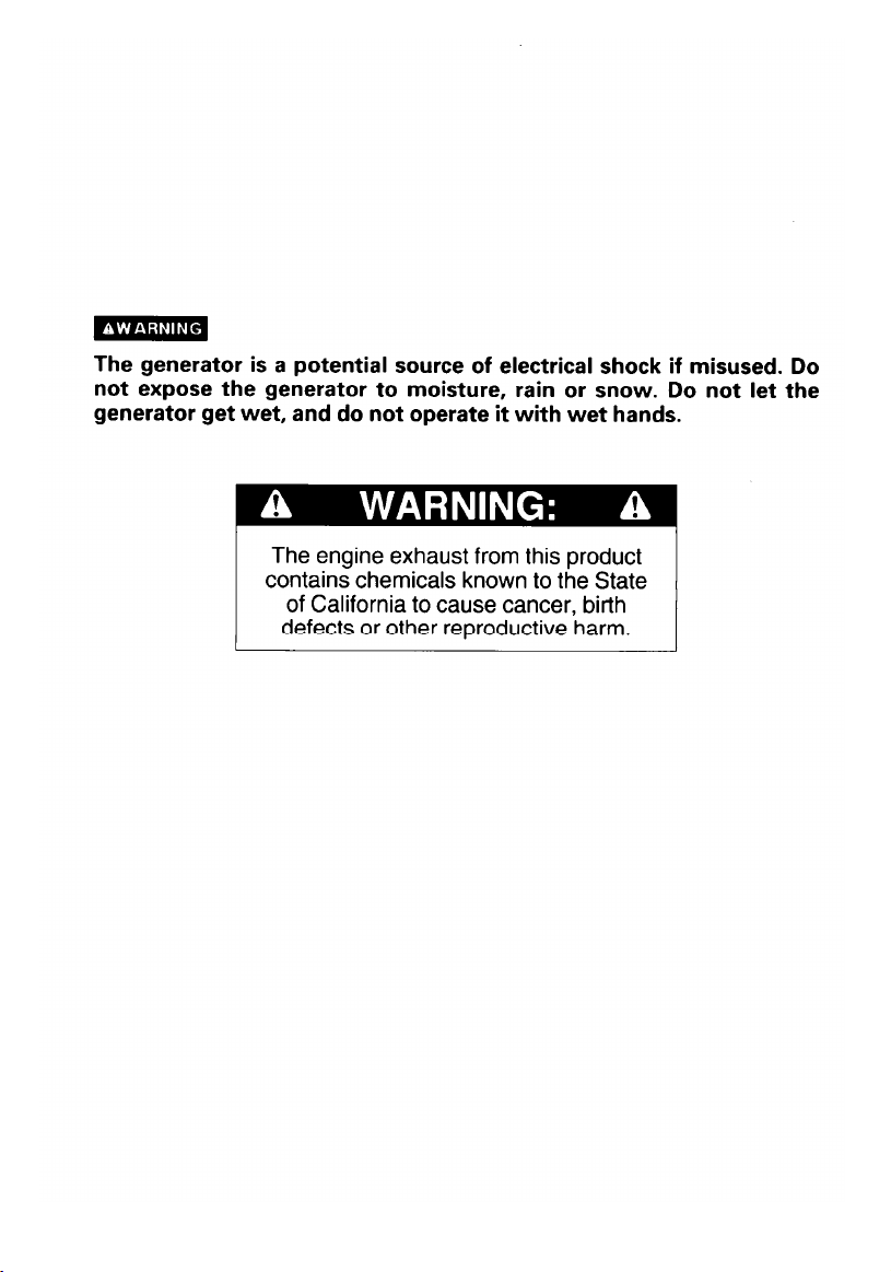
Carbon Monoxide Hazards
l Exhaust contains poisonous carbon monoxide, a colorless and odorless
gas. Breathing exhaust can cause loss of consciousness and may lead to
death.
l If you run the generator in an area that is confined, or even partially
enclosed, the air you breathe could contain a dangerous amount of exhaust
gas. To keep exhaust gas from building up, provide adequate ventilation.
Electric Shock Hazards
l The generator produces enough electric power to cause a serious shock
or electrocution if misused.
l Using a generator or electrical appliance in wet conditions, such as rain or
snow, or near a pool or sprinkler system, or when your hands are wet, could
result in electrocution. Keep the generator dry.
l If the generator is stored outdoors, unprotected from the weather, check all
electrical components on the control panel, before each use. Moisture or
ice can cause a malfunction or short circuit in electrical components which
could result in electrocution.
l Do not connect to a building’s electrical system unless an isolation switch
has been installed by a qualified electrician.
6
Fire and Burn Hazards
The exhaust system gets hot enough to ignite some materials.
-
Keep the generator at least 1 meter (3 feet) away from buildings and
other equipment during operation.
- Do not enclose the generator in any structure.
-
Keep flammable materials away from the generator.
The muffler becomes very hot during operation and remains hot for a while
after stopping the engine. Be careful not to touch the muffler while it is hot.
Let the engine cool before storing the generator indoors.
Gasoline is extremely flammable and is explosive under certain conditions.
Do not smoke or allow flames or sparks where the generator is refueled or
where gasoline is stored. Refuel in a well-ventilated area with the engine
stopped.
Fuel vapors are extremely flammable and may ignite after the engine has
started. Make sure that any spilled fuel has been wiped up before starting
the generator.
7
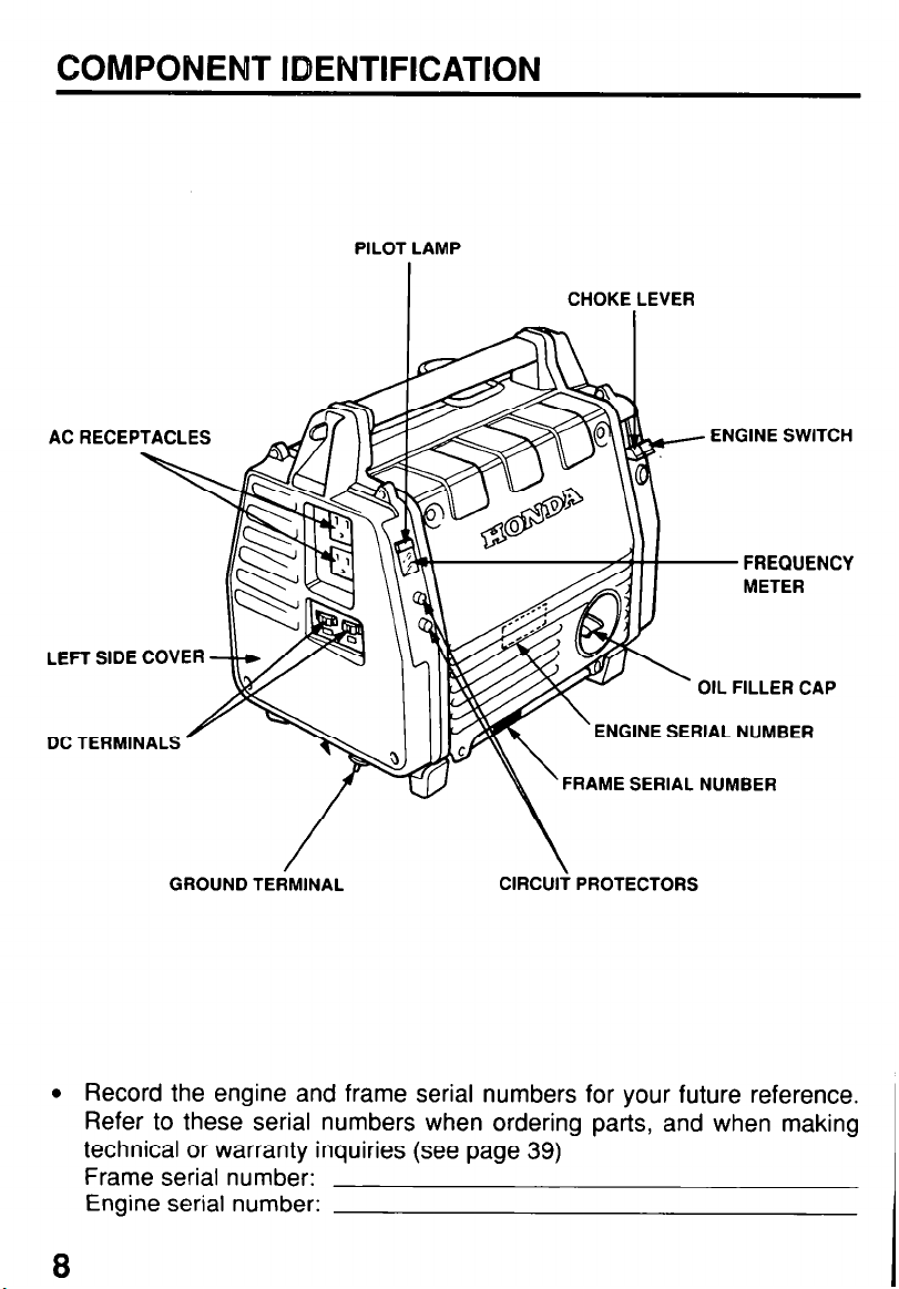
COMPONENT IDENTIFICATION
PILOT LAMP
ACRECEPTACLES
LEFT SIDE COVER
DC TERMINALS
GROUND TEdMlNAL
I
ClRCUli PROTECTORS
CHOKE LEVER
FREQUENCY
METER
OIL FILLER CAP
ENGINE SERIAL NUMBER
FRAME SERIAL NUMBER
l Record the engine and frame serial numbers for your future reference.
Refer to these serial numbers when ordering parts, and when making
technical or warranty inquiries (see page 39)
Frame serial number:
Engine serial number:
8
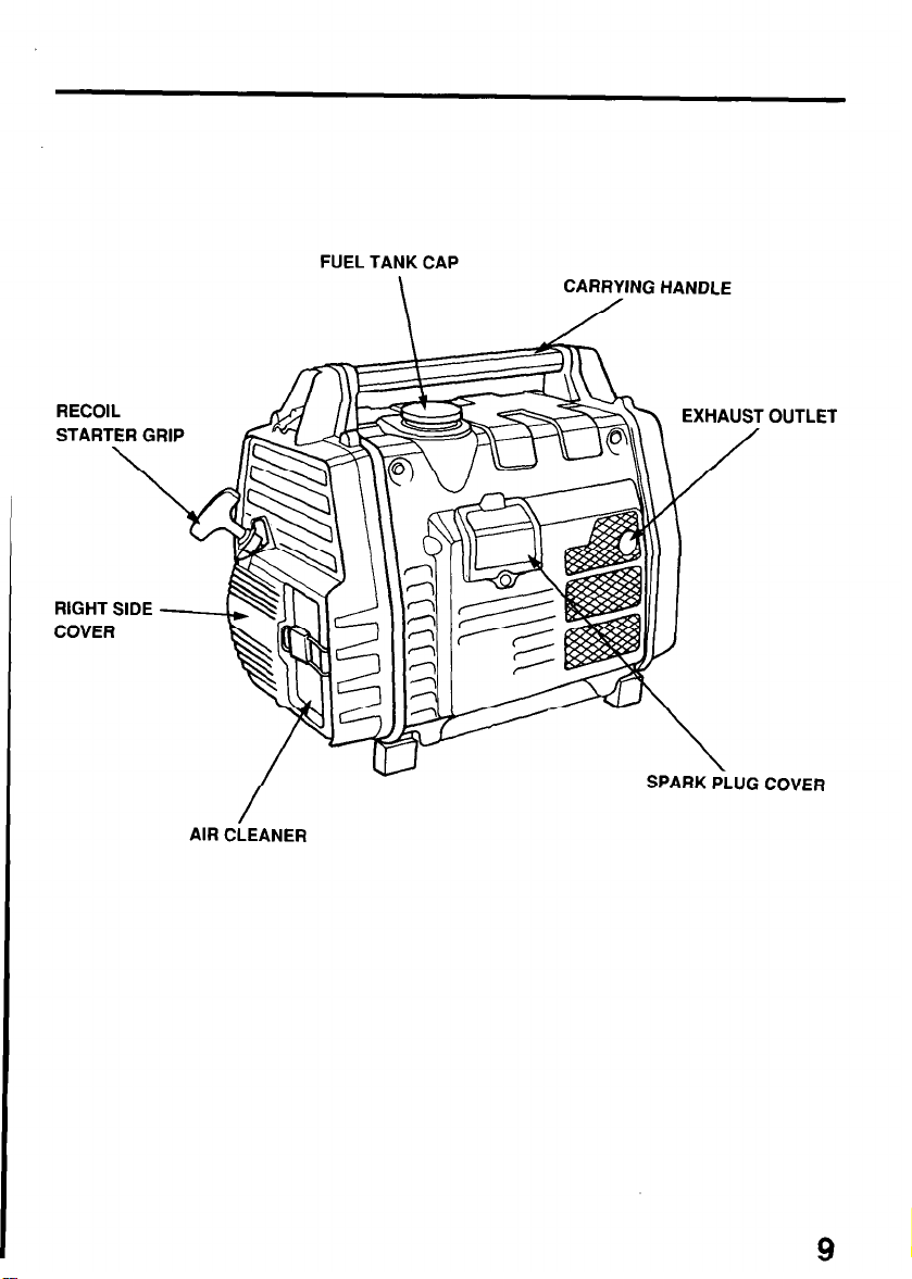
FUEL TANK CAP
\
CARRYING HANDLE
/
RECOIL
STARTER GRIP
\
AIR CLEANER
SPARK P\LUG
OUTLET
COVER
9
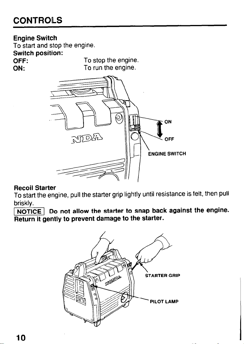
CONTROLS
Engine Switch
To start and stop the engine.
Switch position:
OFF:
ON:
Recoil Starter
To start the engine, pull the starter grip lightly until resistance is felt, then pull
briskly.
I] Do not allow the starter to snap back against the engine.
Return it gently to prevent damage to the starter.
To stop the engine.
To run the engine.
ON
OFF
NGINE SWITCH
10
STARTER GRIP
PILOT LAMP
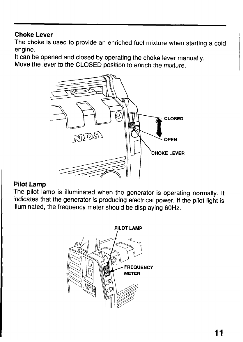
Choke Lever
The choke is used to provide an enriched fuel mixture when starting a cold
engine.
It can be opened and closed by operating the choke lever manually.
Move the lever to the CLOSED position to enrich the mixture.
CLOSED
OPEN
\
CHOKE LEVER
Pilot Lamp
The pilot lamp is illuminated when the generator is operating normally. It
indicates that the generator is producing electrical power. If the pilot light is
illuminated, the frequency meter should be displaying 60Hz.
11
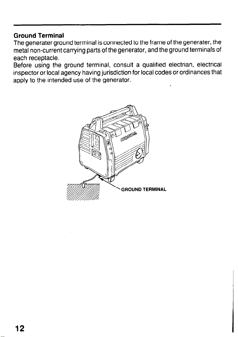
Ground Terminal
The generater ground terminal is connected to the frame of the generater, the
metal non-current carrying parts of the generator, and the ground terminals of
each receptacle.
Before using the ground terminal, consult a qualified electrian, electrical
inspector or local agency having jurisdiction for local codes or ordinances that
apply to the intended use of the generator.
GROUND TERMINAL
12
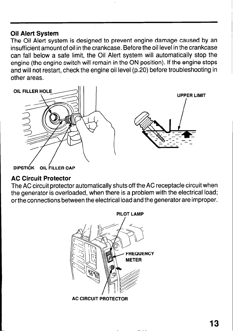
Oil Alert System
The Oil Alert system is designed to prevent engine damage caused by an
insufficient amount of oil in the crankcase. Before the oil level in the crankcase
can fall below a safe limit, the Oil Alert system will automatically stop the
engine (the engine switch will remain in the ON position). If the engine stops
and will not restart, check the engine oil level (p.20) before troubleshooting in
other areas.
OIL FILLER HOLE
DIPSTICK OIL FILLER CAP
UPPER LIMIT
AC Circuit Protector
The AC circuit protector automatically shuts off the AC receptacle circuit when
the generator is overloaded, when there is a problem with the electrical load;
or the connections between the electrical load and the generator are improper.
PILOT LAMP
AC CIRCUIT PROTECTOR
13

DC Terminals
The DC terminals may ONLY be used for charging 12 volt automotive type
batteries.
The terminals are colored red to identify the positive (+) terminal and black to
identify the negative (-) terminal. The battery must be connected to the
generator DC terminals with the proper polarity (battery positive to generator
red terminal and battery negative to the generator black terminal).
DC TERMINAL (RED)
DC TERMINAL (BLACK)
DC Circuit Protector
The DC circuit protector automatically shuts off the DC battery charging circuit
when the generator is overloaded, when there is a problem with the battery;
or the connections between the battery and the generator are improper.
14
GENERATOR USE
Connections to a Building’s Electrical System
Connections for standby power to a building’s electrical system must be made
by a qualified electrician. The connection must isolate the generator power
from utility power, and must comply with all applicable laws and electrical
codes.
m
Improper connections to a building’s electrical system can
allow electrical current from the generator to backfeed into the utility
lines. Such backfeed may electrocute utility company workers or others
who contact the lines during a power outage. Consult the utility com-
pany or a qualified electrician.
-1 Improper connections to a building’s electrical system can
allow electrical current from the utility company to backfeed into the
generator. When utility power is restored, the generator may explode,
burn, or cause fires in the building’s electrical system.
Ground System
Honda portable generators have a system ground that connects generator
frame components to the ground terminals in the AC output receptacles. The
system ground is not connected to the AC neutral wire. If the generator is
tested by a receptacle tester, it will not show the same ground circuit condition
as for a home receptacle.
Special Requirements
There may be Federal or State Occupational Safety and Health Administration
(OSHA) regulations, local codes, or ordinances that apply to the intended use
of the generator. Please consult a qualified electrician, electrical inspector, or
the local agency having jurisdiction.
l In some areas, generators are required to be registered with local utility
companies.
l If the generator is used at a construction site, there may be additional
regulations which must be observed.
15

AC Operation
1. Start the engine (refer to page 23) and make sure the pilot lamp comes on.
If not, the filament may be burnt out.
2. Plug in the appliance.
1 NOTICE ( Substantial overloading will switch off the circuit protector.
Marginal overloading may not switch off the circuit protector, but it will
shorten the service life of the generator.
Be sure that all appliances are in good working order before connecting
them to the generator. If an appliance begins to operate abnormally,
becomes sluggish, or stops suddenly, turn off the generator engine
switch immediately. Then disconnect the appliance and examine it for
signs of malfunction.
NOTE: If an overloaded circuit trips the AC circuit protector, reduce the
electrical load on the circuit, and wait a few minutes before resuming
operation.
The green indicator inside the circuit protector button will pop out to show that
the circuit protector has switched off.
Push the button in to reset the circuit protector.
AC CIRCUIT BREAKER
16
PILOT LAMP
AC RECLPTACLES

DC Operation
The DC terminals may ONLY be used for charging 12 volt automotive-type
batteries.
Connecting the battery cables:
1. Before connecting charging cables to a battery that is installed in a vehicle,
disconnect the vehicle’s ground cable from the battery.
m
The battery gives off explosive gases; keep sparks, flames
and cigarettes away. Provide adequate ventilation when charging or
using batteries.
2. Connect the positive (+) battery cable to the battery positive (+) terminal.
3. Connect the other end of the positive (+) battery cable to the generator
positive (+) terminal.
NEGATIVE
DC TERMINAL (BLACK)
POSITIVE
4. Connect the negative (-) battery cable to the battery negative (-) terminal.
5. Connect the other end of the negative (-) battery cable to the generator
negative (-) terminal.
6. Start the generator.
-1 Do not start the vehicle while the battery charging cables are
connected and the generator is running. The vehicle or the generator
may be damaged.
An overloaded DC circuit, excessive current draw by the battery, or a wiring
problem will trip the DC circuit protector (PUSH button extends out). If this
happens, wait a few minutes before pushing in the circuit protector to resume
operation. If the circuit protector continues to go OFF, discontinue charging
and see your authorized Honda generator dealer.
17

Disconnecting the battery cables:
1. Stop the engine.
2. Disconnect the negative (-) battery cable from the generator negative (-)
terminal.
3. Disconnect the other end of the negative (-) battery cable from the battery
negative (-) terminal.
4. Disconnect the positive (+) battery cable from the generator positive (+)
terminal.
5. Disconnect the other end of the positive (+) battery cable to the battery
positive (+) terminal.
6. Connect the vehicle ground cable to the battery negative (-) terminal.
DC TERMINAL (RED)
18
DC TERMINAL (BLACK)

High Altitude Operation
At high altitude, the standard carburetor air-fuel mixture will be excessively
rich. Performance will decrease, and fuel consumption will increase.
High altitude performance can be improved by installing a smaller diameter
main fuel jet in the carburetor and readjusting the pilot screw. If you always
operate the engine at altitudes higher than 6,000 feet above sea level, have
an authorized Honda generator dealer perform this carburetor modification.
Even with suitable carburetor jetting, engine horsepower will decrease ap-
proximately 3.5%for each 1,000 foot increase in altitude. The effect of altitude
on horsepower will be greater than this if no carburetor modification is made.
-1 If a generator jetted for high altitude is used at a lower
altitude the lean air fuel mixture will reduce performance and may
overheat and seriously damage the engine.
19

PRE-OPERATIOIN CHECK
Engine Oil
-1 Engine oil is a major factor affecting engine performance
and service life. Non-detergent and 2-stroke engine oils will damage the
engine and are not recommended.
Check the oil level BEFORE EACH
USE with the generator on a level surface with the engine stopped.
Use Honda 4-stroke oil, or an equiva-
lent high detergent, premium quality
motor oil certified to meet or exceed
U.S. automobile manufacturer’s re-
quirements for Service Classification
SG, SF/CC, CD.
Motor oils classified SG, SF/CC, CD
will show this designation on the container.
SAE 1 OW-30 is recommended for general, all-temperature use. Other viscosi-
ties shown in the chart may be used when the average temperature in your
area is within the indicated range.
TEMP-20 0
c
-30 -20
AMBIENT TEMPERATURE
20
-10
40 60
0 10 20
80 100°F
30 40°C
1. Remove the oil filler cap and wipe the dipstick clean.
2. Check the oil level by inserting the dipstick into the filler neck without
screwing it in.
3. If the oil level is low, fill to the top of the oil filler neck with the recommended
oil.
UPPER LIMIT
DIPSTICK
OIL FILLER CAP
\
20

Fuel Recommendation
1. Check the fuel level gauge.
2. Refill the tank if the fuel level is low. Do not fill above the shoulder of the fuel
strainer.
Gasoline is extremely flammable and is explosive under certain
conditions.
Refuel in a well-ventilated area with the engine stopped. Do not
smoke or allow flames or sparks in the area where the engine is
refueled or where gasoline is stored.
Do not overfill the fuel tank (there should be no fuel in the filler neck).
After refueling, make sure the tank cap is closed properly and
securely. Be careful not to spill fuel when refueling. Spilled fuel or fuel
vapor may ignite. If any fuel is spilled, make sure the area is dry before
starting the engine.
Avoid repeated or prolonged contact with skin or breathing of vapor.
KEEP OUT OF REACH OF CHILDREN.
Fuel tank capacity: 2.8 ! (0.74 US gal, 0.62 Imp gal)
FUEL TANK CAP
UPPER LIMIT FUEL FILTER
I
SCREEN
Use gasoline with a pump octane rating of 86 or higher
We recommend unleaded gasoline because it produces fewer engine and
spark plug deposits and extends exhaust system life.
Never use stale or contaminated gasoline or oil/gasoline mixture. Avoid
getting dirt or water in the fuel tank.
21

Occasionally you may hear light “spark knock” or “pinging” (metallic rapping
noise) while operating under heavy loads. This is no cause for concern.
If spark knock or pinging occurs at a steady engine speed, under normal load,
change brands of gasoline. If spark knock or pinging persists, see an
authorized Honda generator dealer.
[ NOTICE 1 Running the engine with persistent spark knock or pinging
can cause engine damage.
Running the engine with persistent spark knock or pinging is misuse, and the
Distributor’s Limited Warranty does not cover parts damaged by misuse.
22

Oxygenated Fuels
Some conventional gasolines are being blended with alcohol or an ether
compound. These gasolines are collectively referred to as oxygenated fuels.
To meet clean air standards, some areas of the United States and Canada use
oxygenated fuels to help reduce emissions.
If you use an oxygenated fuel, be sure it is unleaded and meets the minimum
octane rating requirement.
Before using an oxygenated fuel, try to confirm the fuel’s contents. Some
states/provinces require this information to be posted on the pump.
The following are the EPA approved percentages of oxygenates:
ETHANOL - (ethyl or grain alcohol) 10% by Volume
You may use gasoline containing up to 10% ethanol by
volume. Gasoline containing ethanol may be marketed under
the name “Gasohol”.
MTBE - (methyl tertiary butyl ether) 15% by Volume
You may use gasoline containing up to 15% MTBE by volume.
METHANOL - (methyl or wood alcohol) 5% by Volume
You may use gasoline containing up to 5% methanol by
volume as long as it also contains cosolvents and corrosion
inhibitors to protect the fuel system. Gasoline containing
more than 5% methanol by volume may cause starting and/
or performance problems. It may also damage metal, rubber, and plastic parts of your fuel system.
If you notice any undesirable operating symptoms, try another service station
or switch to another brand or gasoline.
Fuel system damage or performance problems resulting from the use of an
oxygenated fuel containing more than the percentages of oxygenates men-
tioned above are not covered under warranty.
23

STARTING/STOPPING THE ENGINE
24
Starting the engine
1. The generator may be hard to start if a load is connected.
2. Move the choke lever to the CLOSE position.
3. Move the engine switch to the ON position.
4. Pull the starter grip until compression is felt, then pull briskly.
1 Do not allow the starter grip to snap back. Return it slowly by NOTICE 1
hand.
5. Move the choke lever to the OPEN position as the engine warms up.
Stopping the engine
In an emergency:
l To stop the engine in an emergency, move the engine switch to the OFF
position.
In normal use:
1. Turn off any AC electrical appliance, and disconnect DC battery charging
cables.
2. Move the engine switch to the OFF position.

MAINTENANCE
Periodic maintenance and adjustment is necessary to keep the generator in
good operating condition. Perform the service and inspection at the intervals
shown in the Maintenance Schedule below.
m Exhaust gas contains poisonous carbon monoxide. Shut off
the engine before performing any maintenance. If the engine must be
run, make sure the area is well ventilated.
-1 Use only genuine HONDA parts or their equivalent for maintenance or repair. Replacement parts which are not of equivalent quality
may damage the generator.
MAINTENANCE SCHEDULE
d at every indicated
ing hour interval, whichev
Combustion chamber and Valves
Fuel tank and
filter
Fuel line
(1) Service more frequently when used in dusty areas.
(2) These items should be serviced by an authorized Honda generator dealer, unless the
owner has the proper tools and is mechanically proficient. See the Honda Shop Manual.
(3) For professional commercial use, log hoursof operation to determine proper maintenance
intervals.
Clean
Check
(Replace if
necessary)
mont
0 (2)
Every 2 years (2)
25

Engine Oil Change
Drain the oil while the engine is warm to assure complete and rapid draining.
1. Remove the oil filler cap.
2. Turn the engine switch OFF and tilt the generator to drain the oil.
3. Refill with the recommended oil (see page 20 and check the oil level).
Oil capacity: 0.35 e (0.37 US qt, 0.31 Imp qt)
Please dispose of used motor oil and the oil containers in a manner that is
compatible with the environment. We suggest you take it in a sealed container
to your local service station or recycling center for reclamation. Do not throw
it in the trash or pour it on the ground.
26

Air Cleaner Service
A dirty air cleaner will restrict air flow to the carburetor. To prevent carburetor
malfunction, service the air cleaner regularly. Service more frequently when
operating the generator in extremely dusty areas.
m Using gasoline or flammable solvent to clean the filter
element can cause a fire or explosion. Use only soapy water or nonflammable solvent.
-1 Never run the generator without the air cleaner. Rapid engine
wear will result.
1. Unsnap the air cleaner case spring, and remove the cleaner case and air
cleaner element.
2. Wash the element in a solution of household detergent and warm water,
then rinse thoroughly, or wash in nonflammable or high flash point solvent.
Allow the element to dry thoroughly.
3. Soak the element in clean engine oil and squeeze out the excess oil. The
engine will smoke during initial startup if too much oil is left in the element.
4. Reinstall the air cleaner element and cleaner case.
CASE SPRING
AIR CLEANER CASE
27

Spark Plug Service
Recommended spark plugs:
BMR4A (NGK)
or W14MR-U (NIPPONDENSO)
To ensure proper engine operation, the spark plug must be properly gapped
and free of deposits.
If the engine has been running, the muffler will be very hot. Be careful not to
touch the muffler.
1. Remove the spark plug cap.
2. Clean any dirt from around the spark plug base.
3. Use the proper size plug wrench to remove the spark plug.
PLUG WRENCH
28
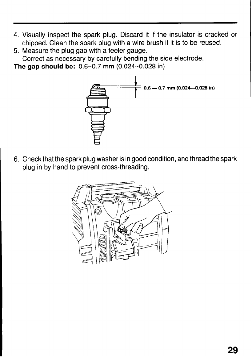
4. Visually inspect the spark plug. Discard it if the insulator is cracked or
chipped. Clean the spark plug with a wire brush if it is to be reused.
5. Measure the plug gap with a feeler gauge.
Correct as necessary by carefully bending the side electrode.
The gap should be: 0.6-0.7 mm (0.024-0.028 in)
0.6 - 0.7 mm (0.024-0.028 in)
6. Check that the spark plug washer is in good condition, and thread the spark
plug in by hand to prevent cross-threading.
29

7. After the spark plug is seated, tighten with a spark plug wrench to compress
the washer.
- If installing a new spark plug, tighten l/2 turn after the spark plug seats
to compress the washer. If reinstalling a used spark plug, tighten 1/8-l /4
turn after the spark plug seats to compress the washer.
I- The spark plug must be securely tightened. An improperly
tightened spark plug can become very hot and could damage the engine.
Never use spark plugs which have an improper heat range. Use only the
recommended spark plugs or equivalent.
30

Spark Arrester Maintenance
If the generator has been running, the muffler will be very hot. Allow to cool
before proceeding.
-1 The spark arrester must be serviced every 100 hours to
maintain its efficiency.
1. Remove the fuel tank cap.
2. Remove the four 5 mm pan-screws, and then remove the rear cover.
Retighten the fuel tank cap.
3. Remove the two 6 mm bolts, and then remove the muffler protector.
REAR COVER
FUEL TANK CAP
iCTOR
4. Remove the three 6 mm bolts that hold the muffler. Move the muffler to the
right and up as far as possible. Carefully remove the spark arrester from the
muffler.
6 mm BOLT (2)
SPARK ARRESTER
31

5. Check for carbon deposits around the exhaust port and the spark arrester.
Use a brush to remove carbon deposits from the spark arrester screen.
Inspect the spark arrester screen for holes or tears. Replace if necessary.
NOTE: The spark arrester must be free of breaks and holes. Replace, if
necessary.
6. Install the spark arrester and the muffler in a reverse order.
Check the exhaust pipe gasket and replace if damaged. Reinstall the
muffler and the protector.
32

TRANSPORTING/STORAGE
When transporting the generator, turn engine switch and the fuel valve OFF.
Keep the generator level to prevent fuel spillage. Fuel vapor or spilled fuel may
ignite.
w Contact with a hot engine or exhaust system can cause
serious burns or fires. Let the engine cool before transporting or storing
the generator.
Take care not to drop or strike the generator when transporting. Do not place
heavy objects on the generator.
Before storing the unit for an extended period:
1. Be sure the storage area is free of excessive humidity and dust.
2. Service according to the table below:
STORAGE TIME
RECOMMENDED SERVICE PROCEDURE TO
PREVENT HARD STARTING
Less than 1 month
1 to 2 months
2 months to 1 year
1 year or more
*Use gasoline conditioners that are formulated to extend storage life.
Contact your authorized Honda generator dealer for conditioner recommendations.
No preparation required
Fill with fresh gasoline and add gasoline condi-
tioner*.
Fill with fresh gasoline and add gasoline condi-
tioner*.
Drain the carburetor float bowl (page 33).
Fill with fresh gasoline and add gasoline conditioner*.
Drain the carburetor float bowl (page 33).
Remove the spark plug. Put a tablespoon of engine
oil into the cylinder. Turn the engine slowly with the
pull rope to distribute the oil. Reinstall the spark
plug.
Change the engine oil (page 26).
After removal from storage, drain the stored gasoline into a suitable container, and fill with fresh
gasoline before starting.
33

1. Drain the carburetor by loosening the drain screw. Drain the gasoline into
a suitable container.
m Gasoline is extremely flammable and is explosive under
certain conditions. Perform this task in a well ventilated area with the
engine stopped. Do not smoke or allow flames or sparks in the area
during this procedure.
2. Drain the fuel a. With the engine switch ON, re-
move the fuel filler cap.
b. Loosen the drain screw and drain
the fuel into a suitable container.
Retighten the screw.
c. Move the engine switch to OFF.
DRAIN
SCREW
\
62’
LP
r
/’
1
2. Change the engine oil (page 26).
3. Remove the spark plug, and pour about a tablespoon of clean engine oil
into the cylinder. Crank the engines several revolutions to distribute the oil,
then reinstall the spark plug.
4. Slowly pull the starter grip until resistance is felt. At this point, the piston is
coming up on its compression stroke and both the intake and exhaust
valves are closed. Storing the engine in this position will help to protect it
from internal corrosion.
34

1
When the engine will not start:
TROUBLESHOOTING
Is there fuel in the tank?
YES
NO
YES
Isthereenoughoilinthe NO
engine?
YES
1
Is there a spark at the
spark plug?
Be sure there is no
spilled fuel around the
spark plug. Spilled fuel
may ignite.
NO Replace the
- spark plug
To check:
1) Remove the rear cover
2) Remove the spark plug
YES
3) Set the plug side electrode
4) Pull the recoil starter,
p oil.
Still No spark
and spark plug cap, and
clean any dirt from around
the spark plug.
and install the spark plug
in the plug cap.
on the cylinder head to
ground.
sparksshouldjumpacross
the gap.
Refill the fuel tank.
Turn the engine switch
on.
Add the recommended
Take the generator to
* an authorized HONDA
dealer.
start, take the generator
to an authorized HONDA
1) Turn off the engine switch
and loosen the drain
2) Fuel should flow from the
drain when the engine
switch is turned on.

No electricity at the AC receptacles:
36
Is the AC circuit protector on?
NO
- tector button in.
YES
+
Check the electrical appliance or equipment for
any defects
NO DEFECTS
DEFECTS
No electricity at the DC terminals
Push the AC circuit pro-
Take the generator to
w an authorized HONDA
dealer.
l Replace the electrical
appliance or equipment.
* l Take the electrical
appliance or equipment to an electrical
shop for repair.
YES
Take the generator to an
) authorized HONDA
dealer.

WIRING DIAGRAM

SPECIFICATBONS
Dimension
Power product description code
Length x Width x Height
Dry Weight
Engine
Engine Type
Displacement
[Bore x Stroke]
Compression Ratio
Engine Speed
Cooling System
Ignition System
Oil Capacity
Fuel Tank Capacity
Spark Plug
1 EA3
41Ox270x375mm
(16.1 x 10.6 x 14.8 in)
1 22 kg (48.5 ib)
4-stroke, side valve, 1 cylinder
76 cc (4.65 cu in)
(46 x 46 mm (1.81 x 1.81 in)]
16:l
3,600 r.p.m.
Forced air cooling
Transistorized magneto
0.35 e (0.37 us qt)
2.8 Q (0.74 US qt)
BMR-4A (NGK), W14MR-U
(NIPPONDENSO)
I
Generator
AC output
DC output
NOTE: Specifications are subject to change without notice.
$1
Maximum Output
650 VA
Only for charging 12 V
automotive batteries.
Maximum charging output = 8.3 A
38

CUSTOMER SERVICE INFORMATION
Honda power equipment dealership personnel are trained professionals.
They should be able to answer any question you may have. If you encounter
a problem that your dealer does not solve to your satisfaction, please discuss
it with the dealership’s management. The Service Manager or General
Manager can help. Almost all problems are solved in this way.
If you are dissatisfied with the decision made by the dealership’s management, contact the Honda Power Equipment Customer Service Office. You can
writ0 to:
American Honda Motor Co.,lnc.
Honda Power Equipment Division
Customer Service Office
4475 River Green Parkway
Duluth, Georgia 30136-2565
Or telephone:
(404)497-6400
When you write or call, please give us this information:
l Model and serial number (see page 8)
l Name of dealer who sold the generator to you
l Name and address of dealer who services your generator
l Date of purchase
l Your name, address, and telephone number
l A detailed description of the problem
39

Current customer service contact information:
United States, Puerto Rico, and U.S. Virgin Islands:
Honda Power Equipment dealership personnel are trained professionals. They should
be able to answer any question you may have. If you encounter a problem that your
dealer does not solve to your satisfaction, please discuss it with the dealership's
management. The Service Manager or General Manager can help. Almost all problems
are solved in this way.
If you are dissatisfied with the decision made by the dealership's management, contact
the Honda Power Equipment Customer Relations Office. You can write:
American Honda Motor Co., Inc.
Power Equipment Division
Customer Relations Office
4900 Marconi Drive
Alpharetta, GA 30005-8847
Or telephone: (770) 497-6400 M-F, 8:30 am - 7:00 pm EST
When you write or call, please provide the following information:
• Model and serial numbers
• Name of the dealer who sold the Honda power equipment to you
• Name and address of the dealer who services your equipment
• Date of purchase
• Your name, address, and telephone number
• A detailed description of the problem

INDEX
COMPONENT IDENTIFICATION
CONTROLS
AC Circuit Protector..
Choke Lever
DC Circuit Protector..
DC Terminals
Engine Switch ...............................................................................
Ground Terminal.. ........................................................................
Oil Alert System ...........................................................................
Pilot Lamp
Recoil Starter
CUSTOMER SERVICE INFORMATION
GENERATOR USE..
AC Operation
Connecting the battery cables
DC Operation
Disconnecting the battery cables
High Altitude Operation
MAINTENANCE
Air Cleaner Service..
Engine Oil Change ......................................................................
Maintenance Schedule
Spark Arrester Maintenance..
Spark Plug Service ......................................................................
.......................................................................................
................................................................... .13
................................................................................. 11
................................................................... .14
................................................................................
....................................................................................
................................................................................
.......................................................................... 15
................................................................................
...............................................................................
.................................................................................
.....................................................................
.................................................................
........................................................ 8
.......................................... .39
......................................................
.................................................
................................................................ 19
.......................................................
10
14
10
.12
.13
11
10
16
17
17
17
25
27
.26
25
31
.28
40

INDEX
PRE-OPERATION CHECK ...............................................................
Engine Oil .....................................................................................
Fuel Recommendation ................................................................. 21
SAFETY ............................................................................................... 4
Safety Information
Safety Label Locations ................................................................... 4
SPECIFICATIONS
STARTING/STOPPING THE
TRANSPORTING/STORAGE ............................................................
TROUBLESHOOTING
WIRING
DIAGRAM..
..........................................................................
.............................................................................
ENGINE
.......................................................................
.........................................................................
............................................. .24
20
20
6
38
33
35
.37
41

I
MEMO
42

MEMO
43

MEMO
44


 Loading...