

I -
!
w The generator is a potential source of electrical shock
if misused. Do not expose the generator to moisture, rain or snow. Do
not let the generator get wet, and do not operate it with wet hands.
Thank you for purchasing a Honda generator. We want to, help you get the
best results from your new generator and to operate it safely. This manual
contains the information on how to do that; please read it carefully.
This owner’s manual describes the operation and maintenance of the
EG1400X and EG2500X Honda Generators. All information in this publica-
tion is based on the latest product information available at the time of
printing. Honda Motor Co., Ltd. reserves the right to make changes at any
time without notice and without incurring any obligation. No part of this
publication may be reproduced wihtout written permission.
This manual should be considered a permanent part of the generator and
should remain with it if it is resold.
Safety Messages
Your safety and the safety of others is very important. We have provided
important safety messages in this manual and on the generator. Please read
these messages carefully.
A safety message alerts you to potential hazards that could hurt you or
others. Each safety message is preceded by a safety alert symbol A and
one of three words: DANGER, WARNING, or CAUTION.
These mean
! D’
w You WILL be KILLED or SERIOUSLY HURT if you don’t
follow instructions.
A -
!
m You CAN be KILLED or SERIOUSLY HURT if you don’t
follow instructions.
9 A
m You CAN be HURT if you don’t follow instructions.
.
Each message tells you what the hazard is, what can happen, and what you
can do to avoid or reduce injury.
l
Damage Prevention Messages
You will also see other important messages that are preceded by the word
NOTICE.
This word means:
-1 Your generator or other property could be damaged if
you don’t follow instructions.
The purpose of these messages is to help prevent damage to your generator,
other property, or the environment.
1
CONTENTS
SAFETY . . . . . . . . . . . . . . . . . . . . . . . . . . . . . . . . . . . . . . . . . . . . . . . . . . . . . . . . . . . . . . . . . . . . . . . . . . . . . . . . . . . . . . 4
Safety Label Locations . . . . . . . . . . . . . . . . . . . . . . . . . . . . . . . . . . . . . . . . . . . . . . . . . . . . . . . . . . . . 4
Safety tnformation . . . . . . . . . . . . . . . . . . . . . . . . . . . . . . . . . . . . . . . . . . . . . . . . . . . . . . . . . . . . . . . . . .
COMPONENT IDENTIFICATION
. . . . . . . . . . . . . . . . . . . . . . . . . . . . . . . . . . . . . . . . . . . . . . 3
6
CONTROLS ..............................................................................
Engine Switch ......................................................................
Recoil Starter ........................................................................ 1 0
Fuel Valve ............................................................................ 11
Choke Lever ......................................................................... 11
Circuit Breaker
Grond Terminal ...................................................................... I 2
Oil Alert System
DC Terminals ........................................................................ I 3
DC Circuit Protector .............................................................. I 3
GENERATOR USE.. ..................................................................
Connections to a Building’s Electrical System ......................
Generator Ground Circuits .................................................... I 4
AC Applications.. ....................................................................
AC Operation ........................................................................
DC Operation
Disconnecting the battery cables ........................................ 18
High Altitude Operation .......................................................... 1 9
PREOPERATION CHECK
Engine Oil ............................................................................ 20
Fuel Recommendation
STARTING THE ENGINE.. ...................................................... 23
STOPPING THE ENGINE ...................................................... 23
......................................................................
....................................................................
...................................................................... 17
...................................................... 20
........................................................ 21
1 0
10
1 2
13
I 4
14
1 5
16
2
MAINTENANCE .
Maintenance
Tool Kit ..................................................................................
Engine Oil Change
Air Cleaner Service
Fuel Sediment
Spark Plug Service
Spark Arrester Maintenance
TRANSPORTING/STORAGE
Storage procedure
TROUBLESHOOTING ............................................................
WIRING DIAGRAM
SPECIFICATIONS
WARRANTY SERVICE.. ..........................................................
INDEX.. .........................
.......................................................................
Schedule .......................................................... 24
................................................................
................................................................
Cup Cleaning ................................................. 26
................................................................ 29
..................................................
..................................................
................................................................
....................................................................
..................................................................
. ..........................................................
24
25
26
27
31
32
33
34
36
37
36
39
3
T
SAFETY
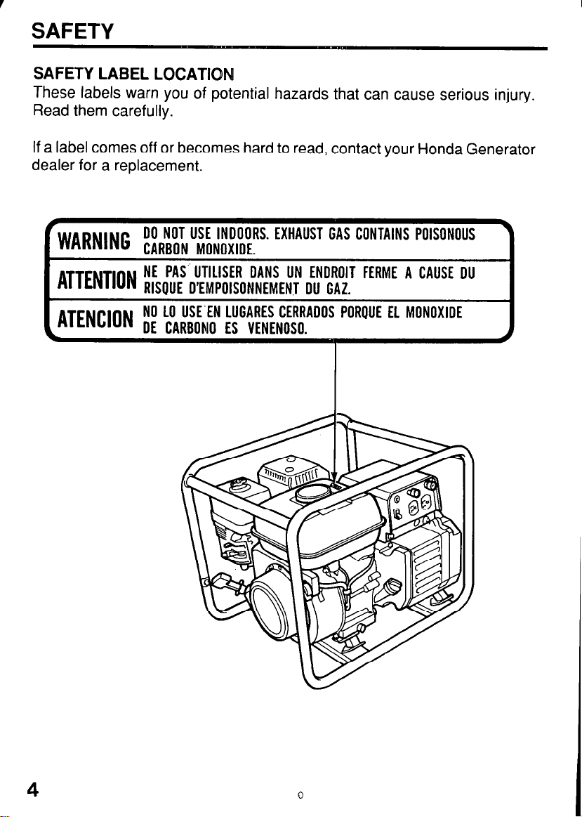
SAFETY LABEL LOCATPON
These labels warn you of potential hazards that can cause serious injury.
Read them carefully.
If a label comes off or becomes hard to read, contact your Honda Generator
dealer for a replacement.
rWARNINc DO NOT USE INDOORS. EXHAUST GAS CONTAINS POISONOUS
J
CARBON MONOXIDE.
ATTENTION NE PAS” UTILISER OANS UN ENOROIT FERME A CAUSE DU
RISGUE D’EMPOISONNEMENT DU GAZ.
ATENCj()N NO LO USE’EN LUGARES CERRADOS POROUE EL MONOXIDE
DE CARBON0 ES VENENOSO.
4
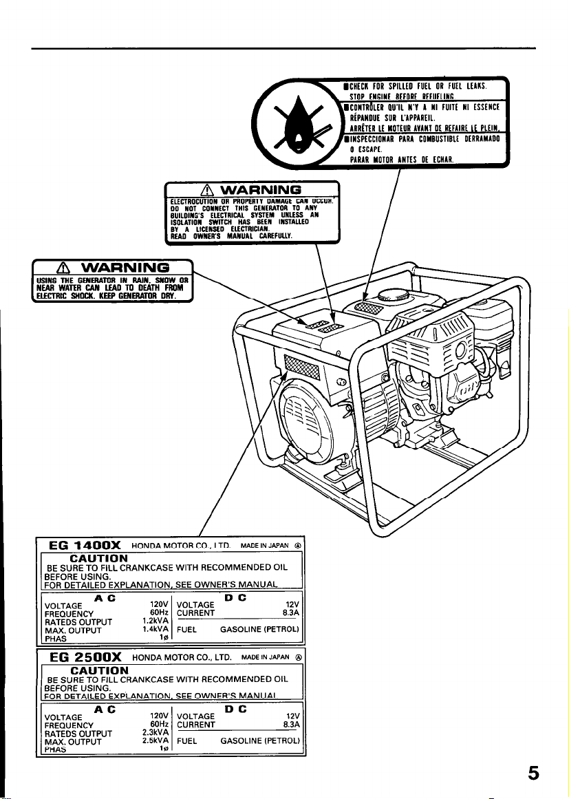
ICRfCK KJR SPlllfD fUfl OR fUf1
STOP tN6lNt BffORf RtfUfllN6.
RiPANOUf SUR L’APPARflL.
hRRiltR Lt HOTfUR AVANI Of RtRlRt It PlflN.
LtlKS.
l
EG
1400x
I.
CAUTION
BE SURE TO FILL CRANKCASE WITH RECOMMENDED OIL
BEFORE USING.
FOR DETAILED EXPLANATION, SEE OWNER’S MANUAL
MAX. OUTPUT
DYdC
CAUTION
BE SURE TO FILL CRANKCASE WITH RECOMMENDED OIL
BEFORE USING.
FOR DETAILED EXPLANATION, SEE OWNER’S MANUAL
FREQUENCY
RATEDS OUTPUT
MAX. OUTPUT
HONDA MOTOR CO., LTD. MADE IN JAPAN Q
1.4kVA FUEL
16
HONDA MOTOR CO., LTD. MADEINJAPAN 8
120V VOLTAGE
60Hz CURRENT 6.3A
2.3kVA
2.5kVA FUEL
GASOLINE (PETROL) 11
DC
GASOLINE (PETROL)
12v
6.3A
12v
PARAR MOTOR ANTfS Of fCHAR.
l
5
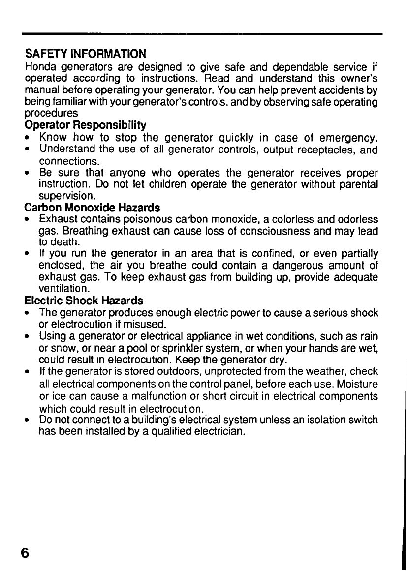
SAFETY INFORMATION
Honda generators are designed to give safe and dependable service if
operated according to instructions. Read and understand this owner’s
manual before operating your generator. You can help prevent accidents by
being familiar with your generator’s controls, and by observing safe operating
procedures
Operator Responsibility
l
Know how to stop the generator quickly in case of emergency.
l
Understand the use of all generator controls, output receptacles, and
connections.
l
Be sure that anyone who operates the generator receives proper
instruction. Do not let children operate the generator without parental
supervision.
Carbon Monoxide Hazards
l
Exhaust contains poisonous carbon monoxide, a colorless and odorless
gas. Breathing exhaust can cause loss of consciousness and may lead
to death.
l
If you run the generator in an area that is confined, or even partially
enclosed, the air you breathe could contain a dangerous amount of
exhaust gas. To keep exhaust gas from building up, provide adequate
ventilation.
Electric Shock Hazards
l
The generator produces enough electric power to cause a serious shock
or electrocution if misused.
l
Using a generator or electrical appliance in wet conditions, such as rain
or snow, or near a pool or sprinkler system, or when your hands are wet,
could result in electrocution. Keep the generator dry.
l
If the generator is stored outdoors, unprotected from the weather, check
all electrical components on the control panel, before each use. Moisture
or ice can cause a malfunction or short circuit in electrical components
which could result in electrocution.
l
Do not connect to a building’s electrical system unless an isolation switch
has been installed by a qualified electrician.
6
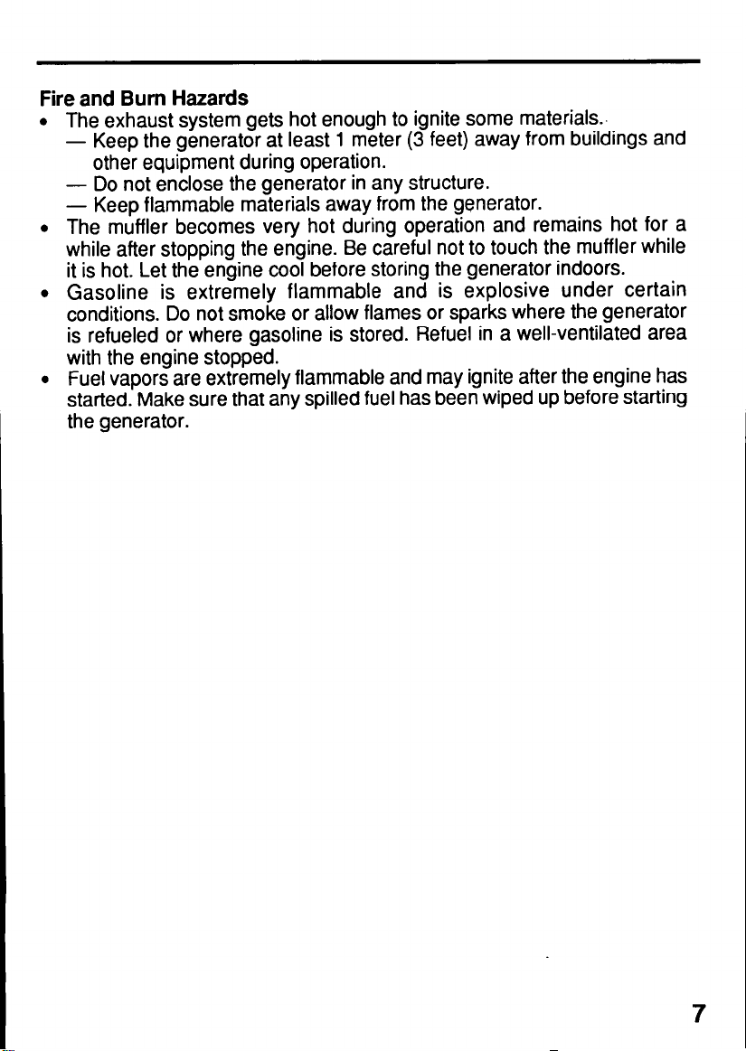
Fire and Burn Hazards
The exhaust system gets hot enough to ignite some materials..
-
Keep the generator at least 1 meter (3 feet) away from buildings and
other equipment during operation.
- Do not enclose the generator in any structure.
-
Keep flammable materials away from the generator.
The muffler becomes very hot during operation and remains hot for a
while after stopping the engine. Be careful not to touch the muffler while
it is hot. Let the engine cool before storing the generator indoors.
Gasoline is extremely flammable and is explosive under certain
conditions. Do not smoke or allow flames or sparks where the generator
is refueled or where gasoline is stored. Refuel in a well-ventilated area
with the engine stopped.
Fuel vapors are extremely flammable and may ignite after the engine has
started. Make sure that any spilled fuel has been wiped up before starting
the generator.
7
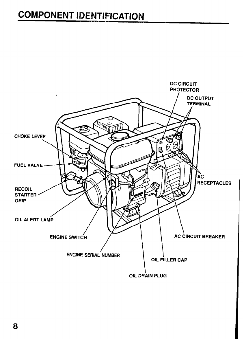
COMPONENT IDENTIFICATION
DC CIRCUIT
PROTECTOR
DC OUTPUT
TERMINAL
CHOKE LEVER
FUEL VALVE +-i-p ~
\\\w
ENGINE SWITCiH
ENGINE SERIAL NUMBER
-
/
OIL FILLER CAP
OIL DRAIN PLUG
AC CIRCUIT BREAKER
I
8
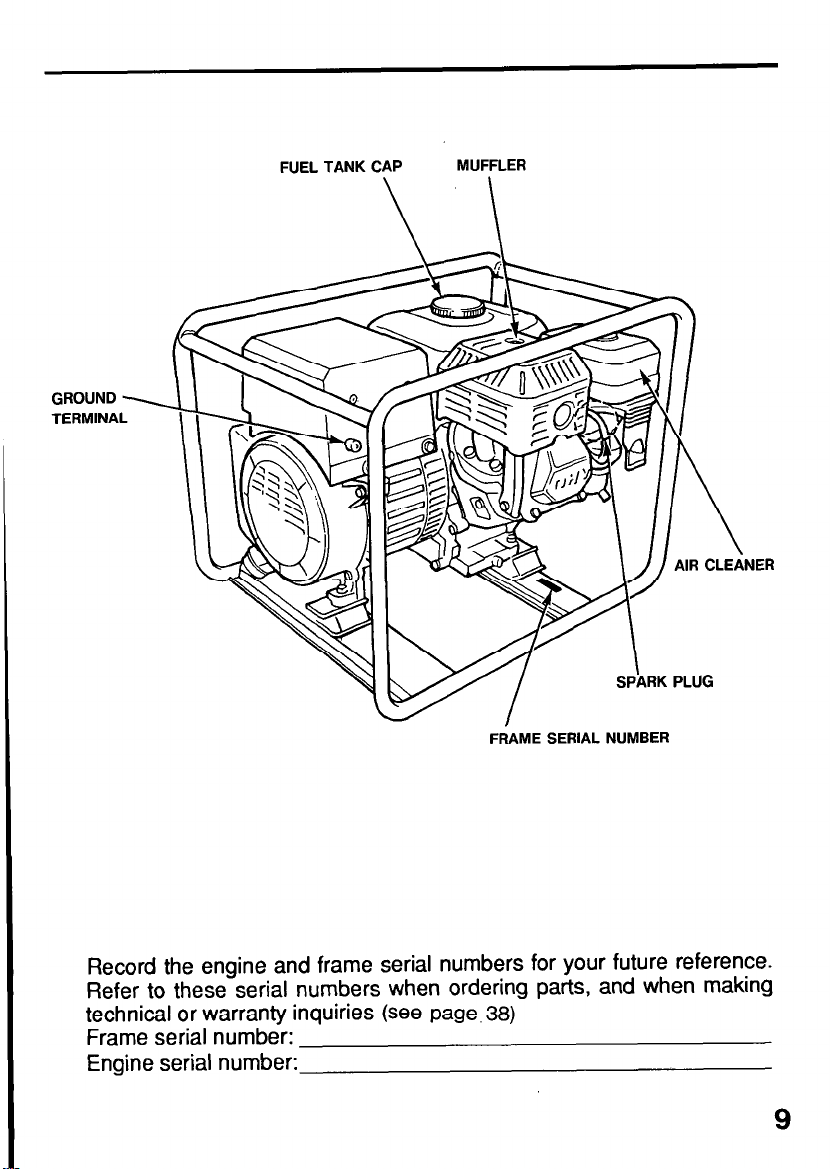
GROUND
TERMINA
FUEL TANK CAP
MUFFLER
NER
FRAME SERIAL NUMBER
Record the engine and frame serial numbers for your future reference.
Refer to these serial numbers when ordering parts, and when making
technical or warranty inquiries (see page, 38)
Frame serial number:
Engine serial number:
9
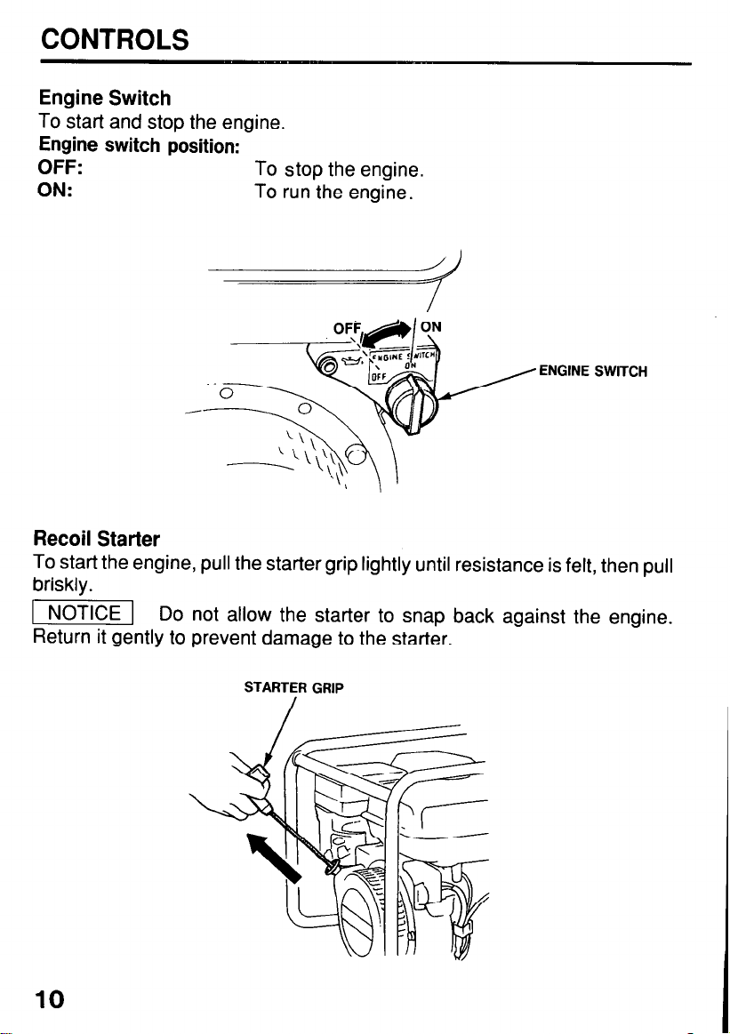
CONTROLS
Engine Switch
To start and stop the engine.
Engine switch position:
OFF:
ON:
Recoil Starter
To start the engine, pull the starter grip lightly until resistance is felt, then pull
briskly.
1 NOTICE 1 Do not allow the starter to snap back against the engine.
Return it gently to prevent damage to the starter.
To stop the engine.
To run the engine.
10
STARTER GRIP
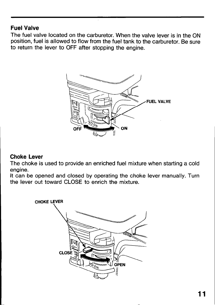
Fuel Valve
The fuel valve located on the carburetor. When the valve lever is in the ON
position, fuel is allowed to flow from the fuel tank to the carburetor. Be sure
to return the lever to OFF after stopping the engine.
FUEL VALVE
Choke Lever
The choke is used to provide an enriched fuel mixture when starting a cold
engine.
It can be opened and closed by operating the choke lever manually. Turn
the lever out toward CLOSE to enrich the mixture.
CHOKE LEVER
\
11
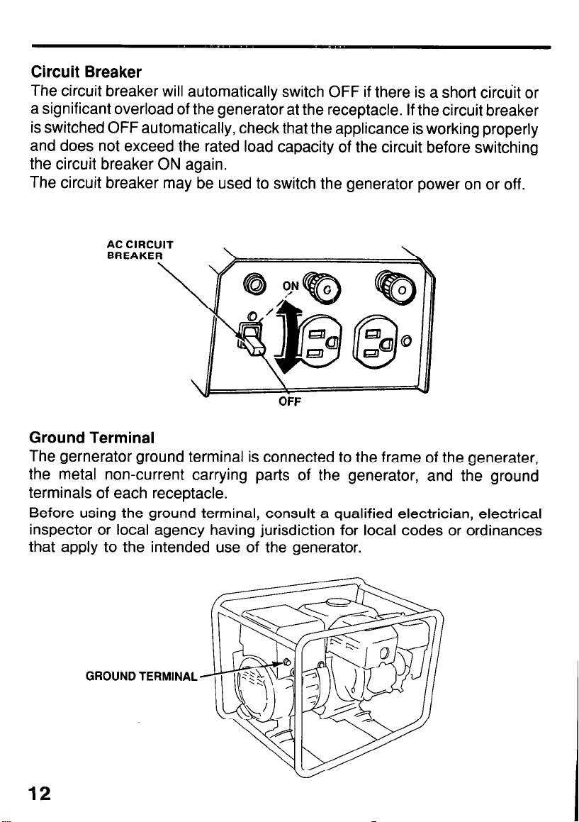
Circuit Breaker
The circuit breaker will automatically switch OFF if there is a short circuit or
a significant overload of the generator at the receptacle. If the circuit breaker
is switched OFF automatically, check that the applicance is working properly
and does not exceed the rated load capacity of the circuit before switching
the circuit breaker ON again.
The circuit breaker may be used to switch the generator power on or off.
Ground Terminal
The gernerator ground terminal is connected to the frame of the generater,
the metal non-current carrying parts of the generator, and the ground
terminals of each receptacle.
Before using the ground terminal, consult a qualified electrician, electrical
inspector or local agency having jurisdiction for local codes or ordinances
that apply to the intended use of the generator.
12
GROUND TERMINAL

Oil Alert System
The Oil Alert system is designed to prevent engine damage caused by an
insufficient amount of oil in the crankcase. Before the oil level in the
crankcase can fall below a safe limit, the Oil Alert system will automatically
shut down the engine (the engine switch will remain in the ON position). If the
Oil Alert system shuts down the engine, the Oil Alert lamp will flash when you
operate the starter, and the engine will not start. If this occurs, add engine oil
(P.20).
OIL ALERT LAMP
DC Terminals
The DC terminals
batteries.
The terminals are colored red to identify the positive (+) terminal and black
to identify the negative (-) terminal. The battery must be connected to the
generator DC terminals with the proper polarity (battery positive to generator
red terminal and battery negative to the generator black terminal).
may ONLY be used for charging
12
volt automotive type
DC Circuit Protector
The DC circuit protector automatically shuts off the DC battery charging
circuit when the generator is overloaded, when there is a problem with the
battery or the connections between the battery and the generator are
improper.
DC CIRCUIT
13

GENERATOR USE
Connections to a Building’s Electrical System
Connections for standby power to a building’s electrical system must be
made by a qualified electrician. The connection must isolate the generator
power from utility power, and must comply with all applicable laws and
electrical codes.
Improper connections to a building’s electrical system
trical current from the generator to backfeed into the
utility lines. Such backfeed may electrocute utility company workers
or others who contact the lines during a power outage. Consult the
utility company or a qualified electrician
A
m Improper connections to a buildng’s electrical system can
allow electrical current from the utility company to backfeed into the
generator. When utility power is restored, the generator may explode,
burn, or cause fires in the building’s electrical system.
Ground System
Honda portable generators have a system ground that connects generator
frame components to the ground terminals in the AC output receptacles. The
system ground is not connected to the AC neutral wire. If the generator is
tested by a receptacle tester, it will not show the same ground circuit
condition as for a home receptacle.
8
Special Requirements
There may be Federal or State Occupational Safety and Health Administration (OSHA) regulations, lacal codes, or ordinances that apply to the
intended use of the generator. Please consult a qualified electrician,
electrical inspector, or the local agency having jurisdiction.
l
In some areas, generators are required to be registered with local utility
companies.
l
If the generator is used at a construction site, there may be additional
regulations which must be observed.
14

AC Applications
Before connecting an appliance or power cord to the generator:
l
Make sure that it is in good working order. Faulty appliances or power
cords can create a potential for electrical shock.
l
If an appliance begins to operate abnormally, becomes sluggish or stops
suddenly, turn it off immediately. Disconnect the applicance, and determine
whether the problem is the appliance, or if the rated load capacity of the
generator has been exceeded.
l
Make sure that the electrical rating of the tool or appliance does not
exceed that of the generator, Never exceed the maximum power rating
of the generator. Power levels between rated and maximum may be used
for no more than 30 minutes.
-1 Substantial overloading will open the circuit breaker.
Exceeding the time limit for maximum power operation or slightly
overloading the generator may not switch the circuit breaker OFF, but
will shorten the service life of the generator.
Limit operation requiring maximum power to 30 minutes.
Maximum power is:
EG1400X: 1.4KVA, EG2500X: 2.5KVA
For continuous operation, do not exceed the rated power.
Rated power is:
EGl400X: 1.2KVA, EG2500X: 2.3KVA
In either case, the total.power requirements (VA) of all appliances connected
must be considered. Appliance and power tool manufacturers usually list
rating information near the model number or serial number.
15

AC Operation
1. Start the engine(refer to page 23).
2. Switch ON the AC circuit breaker.
3. Plug in the appliance.
Most motorized
startup.
appliances require more than their rated wattage for
AC CiRCUlT
BREAKER
Do not exceed
the current limit specified for any one receptacle. If an
overloaded circuit causes the AC circuit breaker or circuit protector to
switch OFF, reduce the electrical load on the circuit, wait a few minutes
and then reset the circuit breaker.
16

DC Operation
The DC terminals may ONLY be used for charging 12 volt automotive-type
batteries .
Connecting the battery cables:
1. Before connecting charging cables to a battery that is installed in a vehicle,
disconnect the vehicle’s grounded battery cable.
. -
!
m The battery gives off explosive gases; keep sparks,
flames and cigarettes away. Provide adequate ventilation when charging
or using batteries.
2. Connect the positive (+) battery cable to the battery positive (+) terminal.
3. Connect the other end of the positive (+) battery cable to the generator
positive (+) terminal.
DC CIRCUIT
NEGATIVE
TERMINAL
PQSITIVE TERMINAL
4. Connect the negative (-) battery cable to the battery negative (-) terminal.
5. Connect the other end of the negative (-) battery cable to the generator
negative (-) terminal.
6. Start the generator.
piimq
Do not start the vehicle while the battery charging cables
are connected and the generator is running. The vehicle or the
generator may be damaged.
An overloaded DC circuit, excessive current draw by the battery, or a wiring
problem will trip the DC circuit protector (PUSH button extends out). If this
happens, wait a few minutes before pushing in the circuit protector to resume
operation. If the circuit protector continues to go OFF, discontinue charging
and see your authorized Honda generator dealer.
17

Disconnecting the battery cables:
1. Stop the engine,
2. Disconnect the negative (-) battery cable from the generator negative (-)
terminal.
3. Disconnect the other end of the negative (-) battery cablefrom the battery
negative (-) terminal.
4. Disconnect the positive (+) battery cable from the generator positive (+)
terminal.
5. Disconnect the other end of the positive (+) battery cable from the
battery positive (+) terminal.
6. Reconnect the vehicle grounded battery cable.
DC CIRCUIT
PROTECTOR
NEGATIVE TERMINAL
POSITIVE TERMINAL
18

High Altitude Operation
At high altitude, the standard carburetor air-fuel mixture will be excessively
rich. Performance will decrease, and fuel consumption will increase.
High altitude performance can be improved by installing a smaller diameter
main fuel jet in the carburetor and readjusting the pilot screw. If you always
operate the engine at altitudes higher than 6,000 feet above sea level, have
an authorized Honda generator dealer perform this carburetor modification.
Even with suitable carburetor jetting, engine horsepower will decrease
approximately 3.5% for each 1,000 foot increase in altitude. The effect of
altitude on horsepower will be greater than this if no carburetor modification
is made.
pimicq
If a generator jetted for high altitude is used at a lower
altitude the lean air fuel mixture will reduce performance and may overheat and seriously damage the engine.
19

PRE-OPERATION CHECK
Engine oil
’ -1 Engine oil is a major factor affecting engine performance
and service life. Non-detergent and 2-stroke engine oils will damage
the engine and are not recommended.
.Check the oil level BEFORE EACH
USE with the generator on a level
surface with the engine stopped.
Use Honda 4-stroke oil, or an
equivalent high detergent, premium
quality motor oil certified to meet or
exceed
manufacturer’s requirements for TEMP-i:o .;,” -;:’ ; i. i. 1 I
Service Classification SG, SF/CC, CD.
Motor oils classified SG, SF/CC, CD
will show this designation on the container.
SAE low-30 is recommended for general, all-temperature use. Other
viscosities shown in the chart may be used when the average temperature
in your area is within the indicated range.
1. Remove the oil filler cap and wipe the dipstick clean.
U.S. automobile
30 40-C
AMBIENT TEMPERATURE
2. Check the oil level by inserting the dipstick into the filler neck without
screwing it in.
3. If the level is low, add the recommended oil to the upper mark on the
dipstick. Over filling with oil can cause the engine to smoke after start-up.
UPPER
LEVEL
\
OIL FlLLEd HOLE
I
DIP STICK
OIL FILLER CAP
20

Fuel Recommendation
1. Check the fuel level.
2. Refill the tank if the fuel level is low. Do not fill above the shoulder of the
fuel strainer.
Gasoline is extremely flammable and is explosive under certain
conditions.
Refuel in a well-ventilated area with the engine stopped. Do not
smoke or allow flames or sparks in the area where the engine is
refueled or where gasoline is stored.
Do not overfill the fuel tank (there should be no fuel in the filler neck).
After refueling, make sure the tank cap is closed properly and
securely. Be careful not to spill fuel when refueling. Spilled fuel or
fuel vapor may ignite. If any fuel
is
spilled, make sure the area is dry
before starting the engine.
Avoid repeated or prolonged contact with skin or breathing of vapor.
KEEP OUT OF REACH OF CHILDREN.
Fuel tank Capacity: EG1400X: 2.7 e (0.71 US gal)
EG2500X: 3.7 e (0.98 US gal)
FUEL STRAINER
Use gasoline with a pump octane rating of 86 or higher
We recommend unleaded gasoline because it produces fewer engine and
spark plug deposits and extends exhaust system life.
Never use stale or contaminated gasoline or oil/gasoline mixture. Avoid
getting dirt or water in the fuel tank.
21

Occasionally you may hear light “spark knock” or “pinging” (metallic rapping
noise) while operating under heavy loads. This is no cause for concern.
If spark knock or pinging occurs at a steady engine speed, under normal
load, change brands of gasoline. If spark knock or pinging persists, see an
authorized Honda generator dealer.
-1 Running the engine with persistent spark knock or
pinging can cause engine damage.
Running the engine wilh persistent spark knock or pinging is misuse, and
the Distributor’s Limited Warranty does not cover parts damaged by misuse.
Oxygenated Fuels
Some gasolines are being blended with alcohol or an ether compound to
increase the octane. These gasolines are collectively referred to as oxygenated
fuels:Some areas of the United States use oxygenated fuels to help meet
clean air standards.
If you use an oxygenated fuel, be sure its pump octane rating is 86 or higher.
Ethanol (ethyl or grain alcohol)
Gasoline containing more than 10% ethanol by volume may cause starting
and/or performance problems. Gasoline containing ethanol may be
marketed under the name “Gasohol”.
Methanol (methyl or wood alcohol)
Gasoline containing methanol must contain cosolvents and corrosion
inhibitors to protect the fuel system. Gasoline containing more than 5%
methanol by volume may cause starting and/or performance problems and
may damage metal, rubber and plastic parts of your fuel system.
MTBE (methyl tertiary butyl ether)
You may use gasoline containing up to 15% MTBE by volume.
Before using an oxygenated fuel, try to confirm the fuel’s contents. Some
states (provinces in Canada) require this information to be posted on the
pump. If you notice any undesirable operating symptoms, switch to a
conventional unleaded gasoline. Fuel system damage or performance
problems resulting from the use of an oxygenated fuel are not the
responsibility of Honda and are not covered under warranty.
-1 Oxygenated fuels can damage paint and plastic. Be
careful not to spill fuel when filling your fuel tank. Damage caused by
spilled fuel is not covered under warranty.
22

STARTING THE
ENGINE /STOPPING THE ENGINE
Starting the engine
1. Make sure that the AC circuit breaker is in the OFF position.
The generator may be hard to start if a load is connected.
2. Turn the fuel valve to the ON position.
3. Turn the choke lever to the CLOSE position.
4. Turn the engine switch to the ON position.
5. Pull the starter grip lightly until resistance is felt, then pull briskly.
-1 Do not allow the starter grip to snap back against the
engine. Return it gently to prevent damage to the starter or housing.
6. As the ehgine warm up, slowly turn the choke lever to OPEN position.
Stopping the engine
In an emergency:
1. To stop the engine in an emergency, turn the engine switch to the OFF
position.
In normal use:
1. Turn the AC circuit breaker to the OFF position.
Disconnect DC battery charging cables.
2. Turn the engine switch to the OFF position.
3. Turn the fuel valve to the OFF position.
23

MAINTENANCE
,
Periodic maintenance and adjustment is necessary to keep the generator in
good operating condition. Perform the service and inspection at the intervals
shown in the Maintenance schedule below.
I -
!
m Exhaust gas contains poisonous carbon monoxide.
Shut off the engine bef&e performing bny maintenance. If the engine
must be run, make sure the area is well ventilated.
. 1-1 Use only genuine HONDA parts or their equivalent for
maintenance or repair. Replacement parts which are not of equivalent
quality may damage the generator.
MAINTENANCE SCHEDULE
I
REGULAR SERVICE PERIOD First Every
Performed at every indicated month
or operating hour interval, whichever
comes first.
ITEM
Engine oil
Air cleaner
Sediment Cup
Spark pulg Check-Clean
Spark Arrester Clean
Check level
Change
Check
Clean
Clean
Each
month 3 months 6 months
or or or
use
0
0
20 Hrs.
(3) (3) (3)
0
50 Hrs. 100 Hrs.
0 (1)
Every
0
0
0
0
Every
year
or
300 Hrs.
(3)
Valve clearance Check-Adjust
Fuel tank and strainer Clean
Check
Fuel line
(1) Service more frequently when used in dusty areas.
(2) These items should be serviced by an authorized Honda generator dealer, unless the
owner has the propertools and is mechanically proficient. See the Honda Shop Manual.
(3) For professional commercial use, log hours of operation to determine proper maintenance
intervals.
(Replace if
necessary)
Every 2 years (2)
0
0
24
(2)
(2)
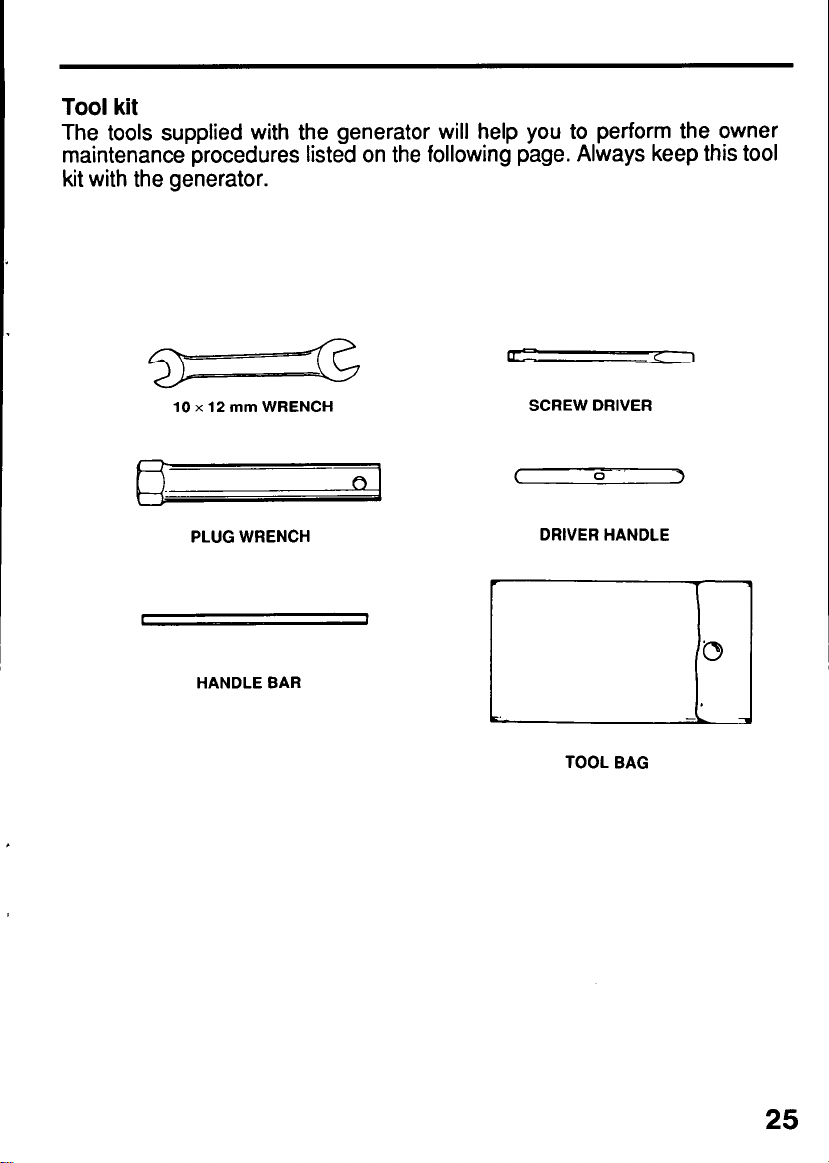
Tool kit
The tools supplied with the generator will help you to perform the owner
maintenance procedures listed on the following page. Always keep this tool
kit with the generator.
10 x 12 mm WRENCH
PLUG WRENCH
t 1
HANDLE BAR
SCREW DRIVER
C
0 -.
DRIVER HANDLE
TOOL BAG
3
25

Engine oil change
Drain the oil while the engine is warm to assure rapid and complete draining.
1. Remove the drain plug and sealing washer, oil filler cap, and drain the oil.
2.
Reinstall the drain plug and sealing washer. Tighten the plug securely.
3. Refill with the recommended oil (see page
oil Capacity: 0.6 e
(0.63US qt, 0.53lm qt)
OIL FILLER CAP
20)
and check the oil level.
! ’
m Used motor oil may cause skin cancer if reDeatedlv left
0
in contact with the skin for prolon&d periods. Although th’is is unlikely
unless you handle used oil on a daily basis, it is still advisable to
thoroughly wash your hands with soap and water as soon as possible
after handling used oil.
Please dispose of used motor oil in a manner that is compatible with the
environment. We suggest you take it in a sealed container to your local
service station or recycling center for reclamation. Do not throw it in the trash
or pour it on the ground.
26

Air cleaner service
A dirty air cleaner will restrict air flow to the carburetor. To prevent carburetor
malfunction, service the air cleaner regularly. Service more frequently when
operating the generator in extremely dusty areas.
. -
!
w Usina gasoline or flammable solvent to clean the filter
element can causk % fire or explosion. Use only soapy water or
nonflammable solvent.
-1 Never run the generator without the air cleaner. Rapid
engine wear will result.
1. Remove the wing nut and the air cleaner cover. Remove the elements
and separate them. Carefully check both elements for holes or tears and
replace if damaged.
2. Foam element: Wash the element in a solution of household detergent
and warm water, then rinse thoroughly; or wash in nonflammable or high
flash point solvent.
Allow the element to dry thoroughly.
Soak the element in clean engine oil, and squeeze out the excess oil.
The engine will smoke during initial start-up if too much oil is left in the
foam.
3. Paper element:Tap the element lightly several times on a hard surface
to remove excess dirt, or blow compressed air through the filter from the
inside out.
Never try to brush the dirt off; brushing will force dirt into the fibers.
Replace the paper element if it is excessively dirty.
WING NUT
AIR CLEANER
COVER
FOAM ELEMENT
PAPER ELEMENT
27

Fuel Sediment Cup Cleaning
The sediment cup prevents dirt or water which may be in the fuel tank from
entering the carburetor. If the engine has not been run for a long time, the
sediment cup should be cleaned.
1. Turn the fuel valve to the OFF position. Remove the sediment cup and O-ring.
2. Clean the sediment cup and O-ring in nonflammable or high flash point solvent.
3. Reinstall the O-ring and sediment cup.
4. Turn the fuel valve ON and check for leakes.
28
FUEL VAL
O-RING
SEDIMENT CUP

Spark Plug Service
Recommended spark plugs:
Bl?RGES (NGK)
W20EPR-U (NIPPONDENSO)
To ensure proper engine operation, the spark plug must be properly gapped
and free of deposits.
If the engine has been running, the muffler will be very hot. Be careful not to
touch the muffler.
1. Remove the spark plug cap.
2. Clean any dirt from around the spark plug base.
3. Use the wrench supplied in the tool kit to remove the spark plug.
PLUG CAP
5. Visually inspect the spark plug. Discard it if the insulator is cracked or
chipped. Clean the spark plug with a wire brush if it is to be reused.
6. Measure the plug gap with a feeler gauge.
correct as necessary by carefully bending the side electrode.
The gap should be: 0.70-0.80
0.70-0.80mm
(0.028-0.031 in)
mm (0.028-0.031 in)
29

7. Check that the spark plug washer is in good condition, and thread the
spark plug in by hand to prevent cross-threading.
8. After the spark plug is seated, tighten with a spark plug wrench to
compress the washer.
If installing a new spark plug, tighten l/2 turn after the spark plug seats
to compress the washer. If reinstalling a used spark plug, tighten
l/8 - l/4 turn after the spark plug seats to compress the washer.
-1 The spark plug must be securely tightened. An
improperly tightened spark plug can become very hot and could
damage the engine.
Never use spark plugs which have an improper heat range. Use only
the recommended spark plugs or equivalent.
30

Spark Arrester Maintenance
If the generator has been running,the muffler will be very hot. Allow it to
cool before proceeding.
pciEq
The spark arrester must be serviced every 100 hours to
maintain its efficiency.
Clean the spark arrester as follows:
1. Loosen @ two 8 mm nuts and 0 6 mm bolt to remove the @ muffler
assembly.
2. Loosen @ four 5 mm screws and remove the @ muffler protector
from the muffler.
3. Loosen @ 4 mm screw and remove @I spark arrester from the muffler.
4. Use a brush to remove carbon deposits from the spark arrester screen.
Inspect the screen for breaks or tears and replace it if necessary.
5. Install the spark arrester and the muffler in reverse order of disassembly.
31

TRANSPORTING/STORAGE
When transporting the generator, turn the engine switch and the fuel valve
OFF. Keep the generator level to prevent fuel spillage. Fuel vapor or spilled
fuel may ignite.
A -
v
m Contact with a hot engine or exhaust system can cause
serious burns or fires. Let the engine cool before transporting or
storing the generator.
Take care not to drop or strike the generator when transporting. Do not
place heavy objects on the generator.
Before storing the unit for an extended period:
1. Be sure the storage area is free of excessive humidity and dust.
2. Service according to the table below:
STORAGE TIME
RECOMMENDED SERVICE PROCEDURE TO
PREVENT HARD STARTING
Less than 1 month No preparation required
1 to 2 months
2 months to 1 year
1 year or more
*Use gasoline conditioners that are formulated to extend storage life.
Contact your authorized Honda generator dealer for conditioner
recommendations.
Fill with fresh gasoline and add gasoline
conditioner*.
Fill with fresh gasoline and add gasoline
conditioner*.
Drain the carburetor float bowl (Page 33).
Drain the fuel sediment cup (Page 28).
Fill with fresh gasoline and add gasoline
conditioner*.
Drain the carburetor float bowl (Page 33).
Drain the fuel sediment cup (Page 28).
Remove the spark plug. Put a tablespoon of engine
oil into the cylinder. Turn the engine slowly with the
pull rope to distribute the oil. Reinstall the spark
plug.
Change the engine oil (Page 26).
After removal from storage, drain the stored gasoline
into a suitable container, and fill with fresh gasoline
before starting.
32

Storage Procedure
1. Drain the carburetor by loosening the drain screw. Drain the gasoline
into a suitable container.
Gasoline is extremely flammable and is explosive under certain
conditions Perform this task in a well ventilated area with the engine
stopped. Do not smoke or allow flames or sparks in the area during this
procedure.
DRAIN SCREW
L-1
2. Change the engine oil.
3. Remove the spark plug, and pour about a tablespoon of clean engine oil
into the cylinder. Crank the engine several revolutions to distribute the oil,
then reinstall the spark plug.
4. Slowly pull the starter grip until resistance is felt. At this point, the piston
is coming up on its compression stroke and both the intake and exhaust
valves are closed. Storing the engine in this position will help to protect it
from internal corrosion.
STARTER GRIP
33

When the engine will not start:
NO
NO
(The oil alert lamp flashes when
cranking the engine.)
YES
Is there a spark from No
the spark plug?
L -
!
w Besure
there is no spilled fueE
around the spark
Plug. 2)
Spilled fuel may ignite.
b Refill the fuel tank.
_L Add the recommend-
ed oil.
To check:
1) Remove the spark plug
cap and clean any dirt from
around the spark plug.
Remove the spark plug
and install the spark plug in
the plug cap.
3)
Set the plug side electrode
on the cylinder head.
4) Crank the engine, sparks
should jump across the
Qw.
the generator to an
authorized Honda
aenerator dealer.
34
-, Clean the fuel
sediment cup.
1) Turn off the engine switch
and loosen the drain
2) Fuel should flow from the
drain when the engine
switch is turned on.
DRAIN SCREW

No electricity at the AC receptacles:
ante or equipment to an
35

I
F.G1400X
I
EG2500X
CONTROL BO)(
r
DNO TERMINAL i
-w
BACK UP
L
W ..__._..__. WHITE
Y ,............ YELLOW
LIGHTBLUE
LIGHT GREEN
. .._.__.... BLUE
. . . . . . . . .
. . . . . . . . .
Bu
Lb
Lg
BROWN
GREEN
R _.___,.,.__._ RED
. . . . . .
. . . . .._._.... GRAY
. . . . . . . . . . .._ BLACK
. . . . . . . . . . . . .
-‘Generator--------
Bt
Br
Gr
L-
G

Dimensions
SPECIFICATIONS
Model EGl400X
Power equipment description code
I
Length x Width x Height
Dry Weight
Engine
1 Model
Engine Type
Displacement
(Bore x Stroke]
Compression Ratio
Engine Speed
Cooling System
Ignition System
Oil Capacity
Fuel Tank Capacity
Spark Plug
EG2500X
EZCJ EZCR
475 x 390 x 400 mm
(18.7 x 15.4 x 15.7 in)
32.0kg (70.5lb) 39.5kg (87.llb)
1 HONDA GXl20Kl
4-stroke, overhead valve, single cylinder
l18cm3 (7.2~~ in) 163cm3 (9.9cu in)
60 x 42mm (2.4 x 1.7 in)
Forced air cooled
Transistorized magneto
I
2.7 e (0.71 USgal)
0.6 e (0.63USqt)
BPRGES (NGK)
W20EPR-U (NIPPONDENSO)
505 x 410 x 415 mm
(19.9 x 16.2 x 16.3 in)
1 HONDA GXl60Kl 1
68 x 45mm (2.7 x 1.8 in)
8.5:1
3600 rpm
3.7 e (0.98 USgal)
Generator
Model
I
Type
Rated voltage
Rated frequency
AC output
DC outpit
NOTE : Specifications are subject to change without notice.
Rated ampere
Rated output
Maximum output
Only for charging 12 V automotive batteries
EGl400X
lO.OA
1.2kVA
1.4kVA 2.5kVA
Maximum charging output = 8.3 A
I
A
12ov
60HZ
EG2500X
19.2A
2.3kVA
I
37

WARRANTY SERVICE
Owner satisfaction
Your satisfaction and goodwill are important to your dealer and to us. All
Honda warranty details are explained in the Distributor’s Limited Warranty.
Normally, any problems concerning the product will be handled by your
dealer’s service department. If you have a warranty problem that has not
been handled to your satisfaction, we suggest you take the following action:
l
Discuss your problem with a member of dealership management. Often
complaints can be quickly resolved at that level. If the problem has
already been reviewed with the Service Manager, contact the owner of
the dealership or the General Manager.
l
If your problem still has not been resolved to your satisfaction, contact
the Power Equipment Customer Service Department of American Honda
Motor Co., Inc.
American Honda Motor Co., Inc.
Power Equipment Customer Service
4475 River Green Parkway
Duluth, Georgia 30136-9420
Telephone: (404) 497-6400
We will need the following information in order to assist you:
- Your name, address, and telephone number
- Product model and serial number
- Date of purchase
- Dealer name and address
- Nature of the problem
After reviewing all the facts involved, you will be advised of what action can
be taken. Please bear in mind that your problem will likely be resolved at the
dealership, using the dealer’s facilities, equipment, and personnel, so it is
very important that your initial contact be with the dealer.
Your purchase of a Honda product is greatly appreciated by both your dealer
and American Honda Motor Co., Inc. We want to assist you in every way
possible to assure your satisfaction with your purchase.
38

Current customer service contact information:
United States, Puerto Rico, and U.S. Virgin Islands:
Honda Power Equipment dealership personnel are trained professionals. They should
be able to answer any question you may have. If you encounter a problem that your
dealer does not solve to your satisfaction, please discuss it with the dealership's
management. The Service Manager or General Manager can help. Almost all problems
are solved in this way.
If you are dissatisfied with the decision made by the dealership's management, contact
the Honda Power Equipment Customer Relations Office. You can write:
American Honda Motor Co., Inc.
Power Equipment Division
Customer Relations Office
4900 Marconi Drive
Alpharetta, GA 30005-8847
Or telephone: (770) 497-6400 M-F, 8:30 am - 7:00 pm EST
When you write or call, please provide the following information:
• Model and serial numbers
• Name of the dealer who sold the Honda power equipment to you
• Name and address of the dealer who services your equipment
• Date of purchase
• Your name, address, and telephone number
• A detailed description of the problem

INDEX
COMPONENT IDENTIFICATION
CONTROLS
Choke Lever
Circuit Breaker
DC Circuit Protector
DC Terminals
Engine Switch
Fuel Valve
Grond Terminal
Oil Alert System
Recoil Starter
GENERATOR USE
AC Applications
AC Operation
Connections to a Building’s Electrical System l -*--*--------- 1 4
DC Operation
Disconnecting the battery cables
Generator Ground Circuits
High Altitude Operation
MAINTENANCE
Air Cleaner Service
Engine Oil Change
Fuel Sediment Cup Cleaning
Maintenance Schedule
Spark Arrester Maintenance
Spark Plug Service
Tool Kit
PREOPERATION CHECK
Engine Oil
Fuel Recommendation
SAFETY
Safety Information
Safety Label Locations
SPECIFICATIONS
STARTING THE ENGINE/STOPPING THE ENGINE -*---****-**-** 23
TRASPORTING/STORAGE
Storage procedure
TROUBLESHOOTING
WARRANTY SERVICE
WIRING DIAGRAM
..................................................................
...............................................................
............................................................
......................................................
. .......................................................
.......
............................................................
..................................................................
............................................................
.........................................................
...............................................................
.........................................................
.........................................................
...............................................................
...............................................................
...............................................................
......................................................
......................................................
......................................................
.....................................................................
..................................................................
...................................................
........................................................................
.........................................................
............................................................
.........................................................
......................................................
......................................................
.........................................................
..........................................
....................................
.............................................
................................................
..........................................
................................................
..........................................
................................................
................................................
................................................
10
11
12
13
13
10
11
12
13
10
14
15
16
17
18
14
19
24
27
26
28
24
31
29
25
20
20
21
37
32
33
34
38
36
8
4
6
4
39

MEM0
40


 Loading...