

Honda CR250R (2004) Owner's Manual
HONDA O/M ’04 CR250R (E) 31KSK6000 00X31-KSK-6000
IMPORTANT NOTICE
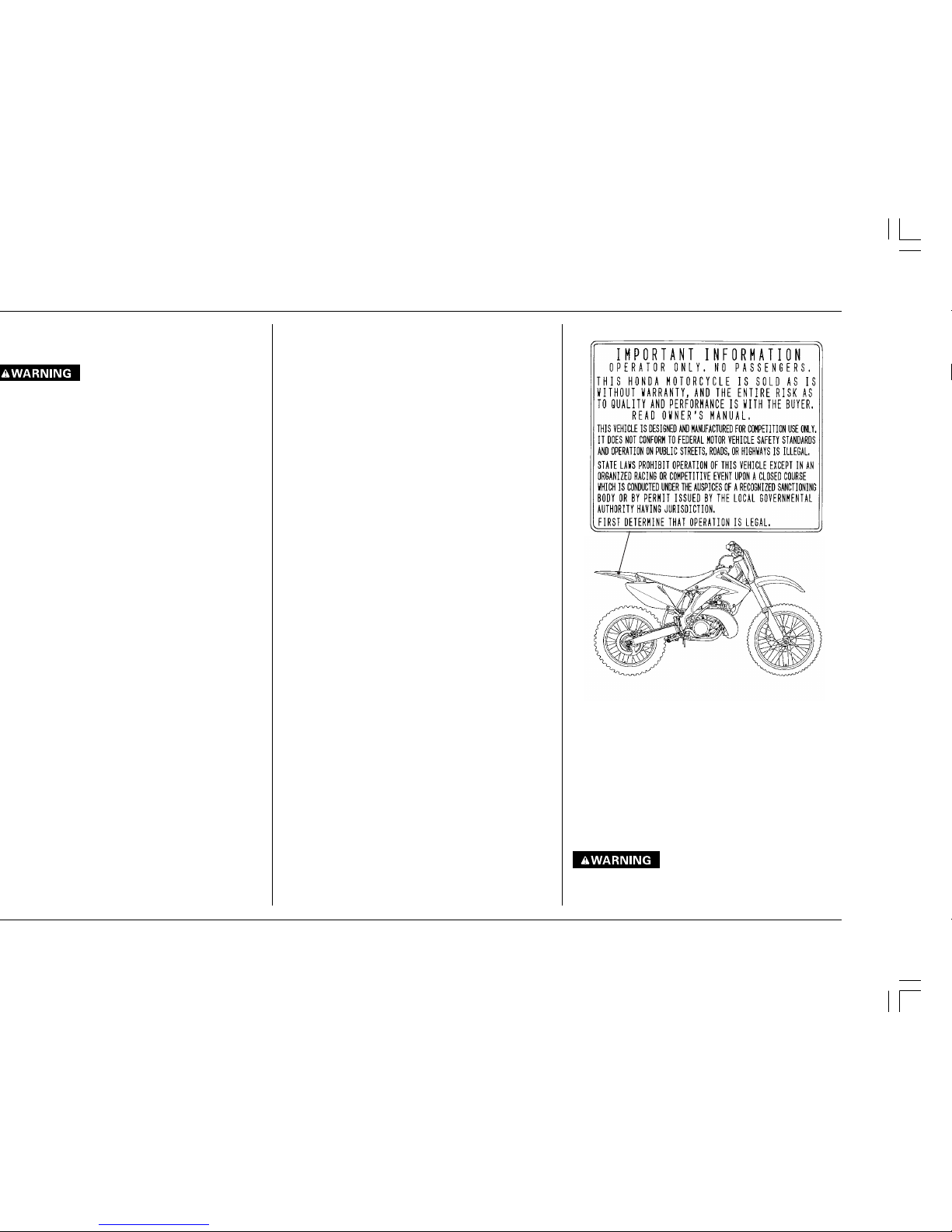
THIS MOTORCYCLE IS DESIGNED AND MANUFACTURED FOR COMPETITION USE ONLY AND IS SOLD
“AS IS” WITH NO WARRANTY. IT DOES NOT CONFORM TO FEDERAL MOTOR VEHICLE SAFETY
STANDARDS AND OPERATION ON PUBLIC STREETS, ROADS, OR HIGHWAYS IS ILLEGAL.
STATE LAWS PROHIBIT OPERATION OF THIS MOTORCYCLE EXCEPT IN AN ORGANIZED RACING OR
COMPETITIVE EVENT UPON A CLOSED COURSE WHICH IS CONDUCTED UNDER THE AUSPICES OF A
RECOGNIZED SANCTIONING BODY OR BY PERMIT ISSUED BY THE LOCAL GOVERNMENTAL
AUTHORITY HAVING JURISDICTION.
FIRST DETERMINE THAT OPERATION IS LEGAL.
OPERATOR ONLY, NO PASSENGERS.
This motorcycle is designed and constructed as an operator-only model. The motorcycle load limit and
seating configuration do not safely permit the carrying of a passenger.
READ THIS MANUAL CAREFULLY.
Pay special attention to statements preceded by the following words:
Indicates severe personal injury or death will result if instructions are not followed.
Indicates a strong possibility of severe personal injury or death if instructions are not followed.
CAUTION:
Indicates a possibility of personal injury or equipment damage if instructions are not followed.
NOTE: Gives helpful information.
This manual should be considered a permanent part of the motorcycle and should remain with the
motorcycle when resold.

HONDA O/M ’04 CR250R (E) 31KSK6000 00X31-KSK-6000
2004
HONDA O/M ’04 CR250R (E) 31KSK6000 00X31-KSK-6000
The CR is a high performance racing motorcycle
utilizing the latest motocross technology. This
motorcycle is intended for competition use by
experienced riders only.
The purpose of this Owner’s Manual is to help ensure
that you obtain the greatest possible satisfaction from
your new CR motocrosser – satisfaction with the performance of the motorcycle, and through success in
competition.
The Service Manual for your CR is available from your
authorized Honda dealer. It is the same manual your
dealer uses. If you plan to do any service on your CR
beyond the standard maintenance procedures included
in this Owner’s Manual, you will find the Service Manual
an effective and worthwhile tool. If your dealer does not
have the Service Manual for your particular year and
model in stock, he can order it.
PROTECTIVE APPAREL
1. Most motorcycle accident fatalities are due to head
injuries: ALWAYS wear an approved motorcycle
helmet. You should also wear a face shield or
goggles, boots, gloves, and protective clothing.
2. The exhaust system becomes very hot during operation, and it remains hot after operation. Never
touch any part of the hot exhaust system. Wear
clothing that fully covers your legs.
3. Do not wear loose clothing which could catch on the
control levers, kickstarter, footpegs, drive chain, or
wheels.
MODIFICATIONS
•
Modification of the motorcycle, or removal of
original equipment may render the vehicle unsafe
or illegal. Obey all federal, state, and local equipment regulations.
Read this WARNING LABEL before you ride.

1
HONDA O/M ’04 CR250R (E) 31KSK6000 00X31-KSK-6000
Fuel ................................................................. 2
Basic Operation ............................................. 3
• Starting The Engine ............................... 3
• Stopping The Engine ............................. 3
• Break-In Procedure ................................. 3
Controls .......................................................... 4
Control Adjustment ....................................... 5
• Clutch Lever Free Play ........................... 5
• Clutch Lever Position ............................. 5
• Throttle Grip ........................................... 6
• Front Brake Lever ................................... 7
• Brake Pedal Height ................................. 7
Adjustment For Personal Fit ......................... 7
• Control Positioning ................................ 7
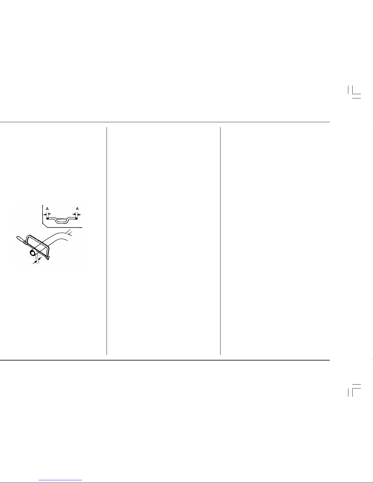
• Handlebar Position, Width & Shape ..... 7
• Additional Individualized
Adjustments............................................ 8
Pre-ride Inspection Check List ..................... 11
Maintenance Schedule................................. 11
General Service Information ....................... 12
Between Moto/Between Practice And Moto
Maintenance ................................................. 12
After Race Maintenance ............................... 13
• After Race Lubrication .......................... 13
• Routine Cleaning ................................... 13
• Pressurized Spray Washers .................. 13
• Condensation Control ........................... 13
• After Cleaning Lubrication .................... 13
General Maintenance ................................... 14
Maintenance Preparations ............................. 17
• Seat ........................................................... 17
• Fuel Tank .................................................. 17
• Subframe ................................................. 19
Maintenance Procedures ............................. 20
• Transmission Oil ................................... 20
• Coolant ................................................... 21
• Spark Plug .............................................. 22
• Ignition ................................................... 22
• Air Cleaner ............................................. 23
• Clutch ..................................................... 24
• RC Valve ................................................. 25
• Reed Valve ............................................. 28
29
• Cylinder Head/Cylinder/Piston ............. 29
30
• Nuts, Bolts, Fasteners ........................... 35
• Handlebar And Steering Head
Bearings ................................................. 35
• Throttle Grip .......................................... 35
• Fuel Line ................................................. 35
• Carburetor .............................................. 36
• Front And Rear Wheels And Tires ....... 36
• Front Suspension .................................. 37
• Rear Suspension ................................... 38
• Brakes ..................................................... 39
• Drive Chain ............................................ 41
• Drive Chain Sliders ................................ 43
• Drive Chain Rollers ................................ 43
• Driven Sprocket ..................................... 43
• Expansion Chamber .............................. 44
• Control Cables ....................................... 44
• Torque Table .......................................... 45
5. CARBURETOR ADJUSTMENT ........................ 46
• Carburetor .............................................. 46
• Tuning For Special Conditions ............. 51
• Spark Plug Coloring Indications ........... 51
6. SUSPENSION ADJUSTMENT ......................... 52
• Race Sag ................................................ 52
• Rear Suspension ................................... 53
• Front Suspension .................................. 55
• Suspension Adjustments Relating To
Specific Track Conditions ..................... 70
• Suspension Adjustment Guidelines .... 71
7. CHASSIS ADJUSTMENTS FOR TRACK
CONDITIONS .................................................... 74
• Rear End ................................................. 74
• Fork Height/Angle .................................. 74
• Wheelbase ............................................. 74
8. GEARING SELECTION ..................................... 74
9. TIRE SELECTION .............................................. 75
10. MAINTENANCE, TUNING & RACING
LOGBOOK ......................................................... 76
11. SPARE PARTS & EQUIPMENT ........................ 78
12. TROUBLESHOOTING....................................... 79
• Poor Performance At Low And Idle
Speeds.................................................... 79
• Poor Performance At High Speed ........ 79
13. CLEANING ........................................................ 80
14. STORAGE.......................................................... 81
• To Prepare The Motorcycle For
Storage ................................................... 81
• Removal From Storage ......................... 81
15. WIRING DIAGRAM ............................................. 82
16. INDEX.................................................................. 83
17. AUTHORIZED MANUALS .................................. 84
2
HONDA O/M ’04 CR250R (E) 31KSK6000 00X31-KSK-6000
• Vegetable oils separate from gasoline more easily
than mineral oils, especially in cold weather. It is
advisable to use mineral oil when ambient temperatures below 0°C (32°F) are expected.
• If the gasoline-oil mixture is left standing in a
container for a long period of time, lubricity will
deteriorate. Use the mixture within 24 hours-or the
time period recommended by the oil manufacturer.
• Once an oil container is opened, the oil must be
used within one month, since oxidation may occur.
CAUTION:
•
Do not mix vegetable and mineral based oils.
•
Gasoline is extremely flammable and is explosive
under certain conditions. Perform this operation in
a well-ventilated area with the engine stopped. Do
not smoke or allow flames or sparks in the area
where gasoline is drained or stored and where the
fuel tank is refueled.
32:1 FUEL OIL MIXING CHARTFUEL
number of 92 or higher. If “knocking” or “pinging”
occurs, try a different brand of gasoline or a higher
octane grade.
the fuel mixture in a clean container, and shake until
thoroughly mixed before filling the fuel tank.
USE PRO Honda HP2 2-STROKE OIL (32:1) OR AN
EQUIVALENT.
Too much oil will cause excessive smoking and
spark plug fouling. Too little oil will cause engine
damage or premature wear.
Fuel
32
Gallons
0.5
1.0
1.5
2.0
2.5
3.0
3.5
4.0
4.5
5.0
5.5
6.0
Ounces
2.0
4.0
6.0
8.0
10.0
12.0
14.0
16.0
18.0
20.0
22.0
24.0
Oil
1
cm
3
59
118
177
237
296
355
414
473
532
591
651
710
Liters
1.89
3.79
5.68
7.57
9.46
11.36
13.24
15.14
17.03
18.92
20.81
22.71
3
HONDA O/M ’04 CR250R (E) 31KSK6000 00X31-KSK-6000
Never run the engine in an enclosed area. The
exhaust contains poisonous carbon monoxide gas
that can cause loss of consciousness and lead to
death.
Attempting to start the engine with the transmission in gear and clutch engaged may result in injury
or damage.
mission in gear by disengaging the clutch before
operating the kickstarter.
ing from the top of the kickstarter stroke, kick through
to the bottom with a rapid, continuous motion.
pushed down as soon as possible to prevent spark
plug fouling.
before riding off, preferably until the side of the
cylinder is very warm to the touch through your
riding glove. Slowly increase rpm and don’t blip
the throttle. Warming the engine is important to
prevent cold seizures.
Break-In Procedure
Help assure your CR’s future reliability and performance by paying extra attention to how you ride during
the first operating day or 15 miles (25 km).
During this period, avoid full-throttle starts and rapid
acceleration.
This same procedure should be followed each time
when:
• Piston is replaced
• Rings are replaced
• Cylinder is replaced
• Crankshaft or crank bearings are replaced
Warm Engine Starting:
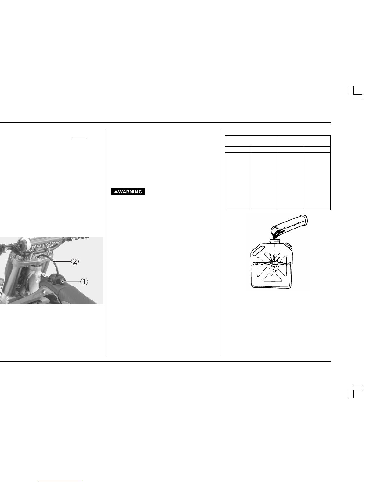
1. Turn the fuel valve ON.
2. Shift the transmission into neutral.
3. Push the choke knob down.
4. Open the throttle (1/8 — 1/4) and operate the kick
starter.
(1) FUEL VALVE (2) CHOKE KNOB
Stopping The Engine
1. Shift the transmission into neutral.
2. Turn the fuel valve OFF.
3. Lightly open the throttle 2 — 3 times, and then close
it.
4. Depress and hold the engine stop button until the
engine stops completely.
NOTE:
• Failure to close the fuel valve may cause the
carburetor to overflow, fill the crankcase with fuel,
and result in hard starting.
(1) ENGINE STOP BUTTON (2) THROTTLE GRIP
OFFON
OFF
2
1
4
HONDA O/M ’04 CR250R (E) 31KSK6000 00X31-KSK-6000
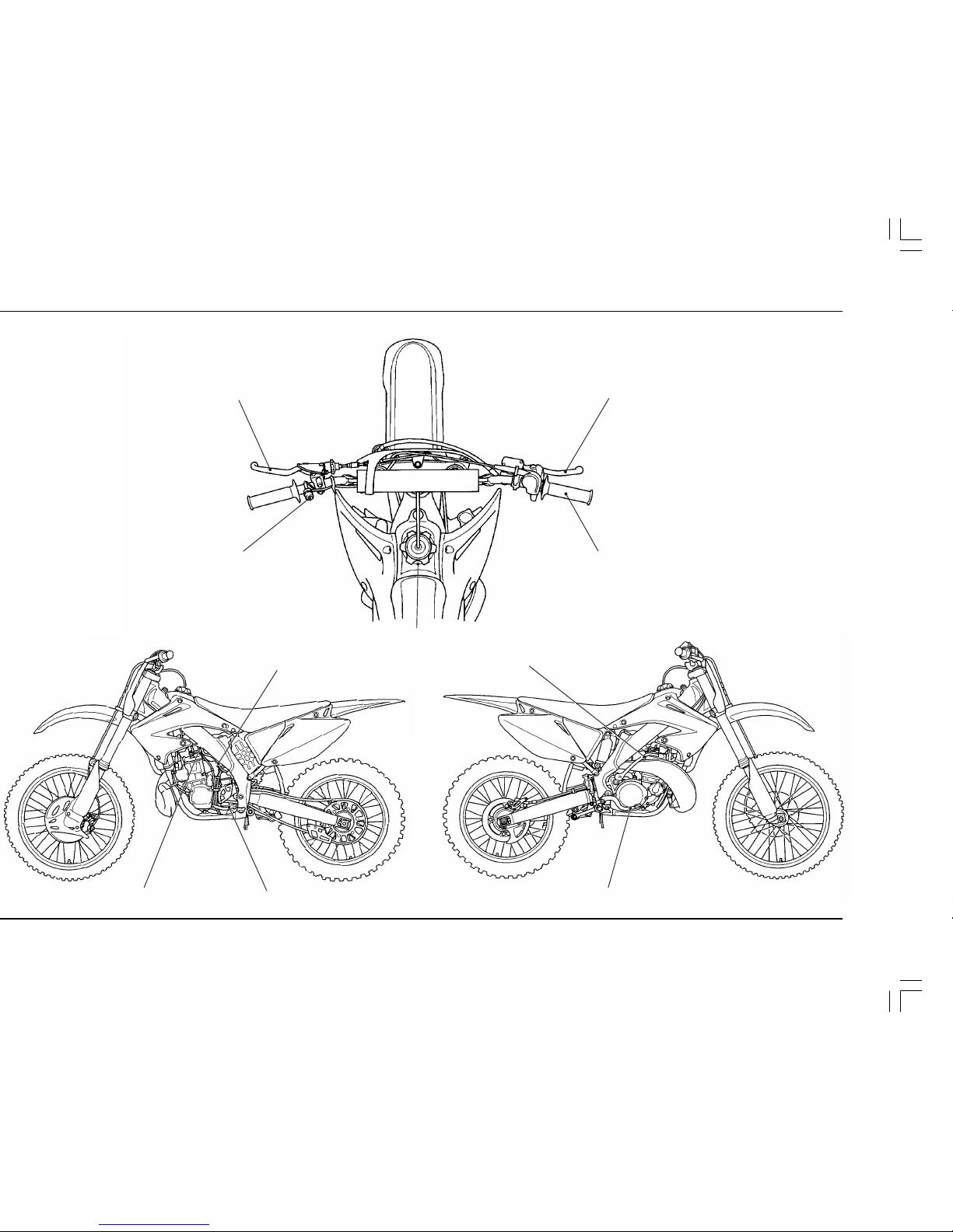
CLUTCH LEVER
FRONT BRAKE LEVER
ENGINE STOP BUTTON
THROTTLE GRIP
CHOKE KNOB
FUEL VALVE
SHIFT LEVER
KICKSTARTER
REAR BRAKE PEDAL
FUEL FILL CAP
5
HONDA O/M ’04 CR250R (E) 31KSK6000 00X31-KSK-6000
1
2
B
1
A
D
1
2
C
F
1
E
1
B
2
1
A
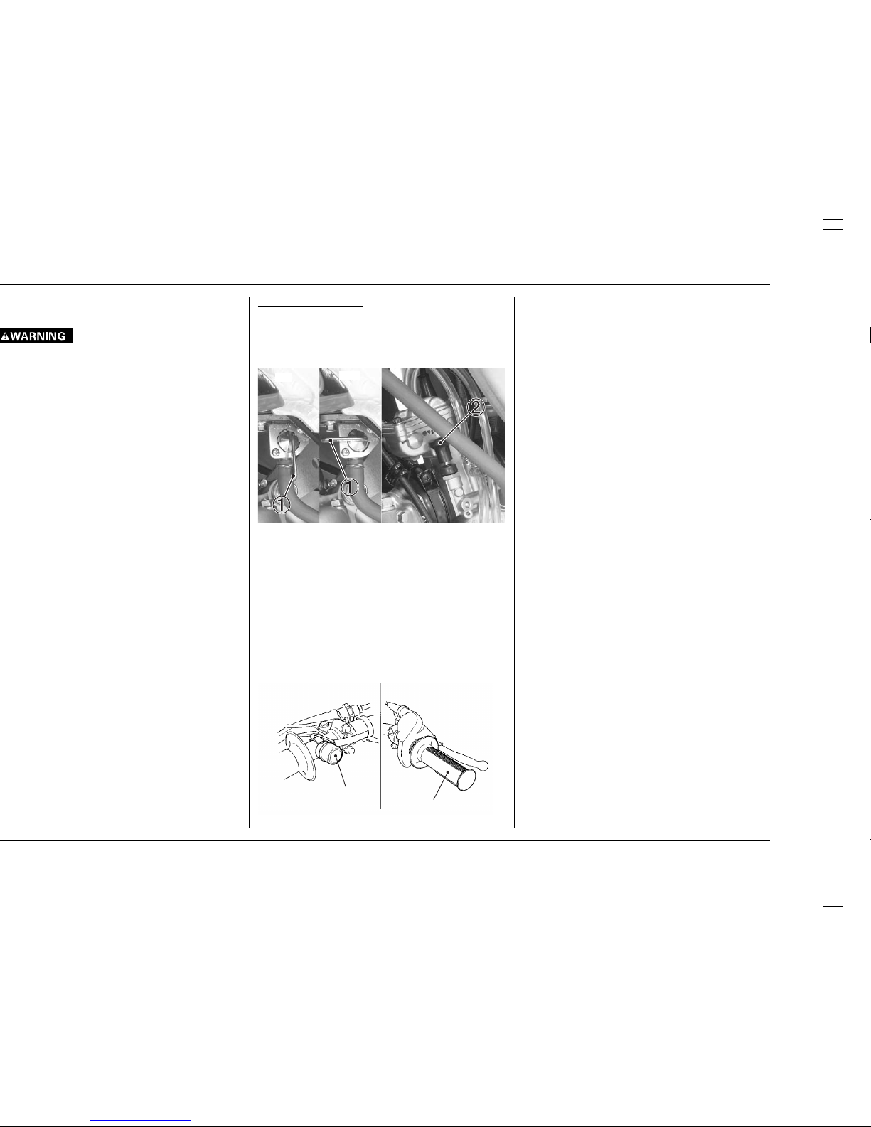
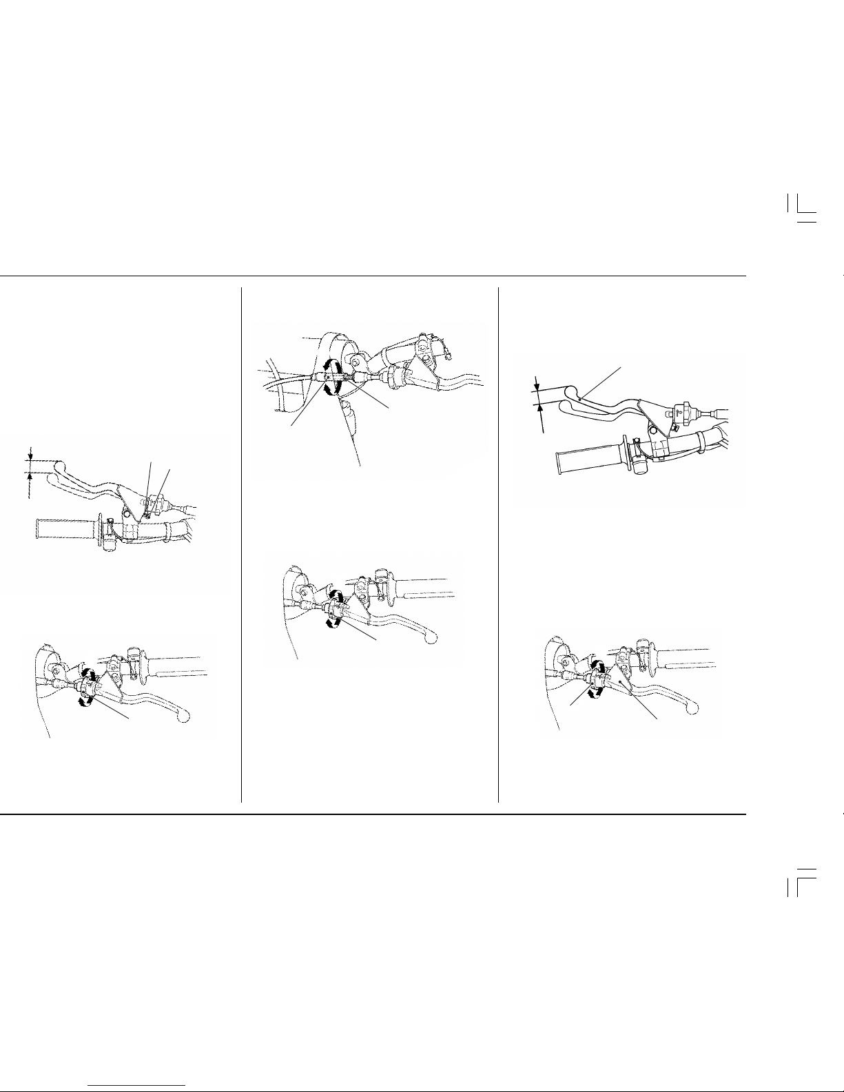
3. Loosen the lock nut and turn the integral cable
adjuster to adjust the clutch lever free play 3/8 – 3/4
in (10 – 20 mm) at the tip of lever. Tighten the lock nut.
(1) LOCK NUT
(2) INTEGRAL CABLE ADJUSTER
(3) INCREASE
(4) DECREASE
4. Adjust the clutch cable end adjuster for minor
adjustment.
(1) CABLE END ADJUSTER
(E) INCREASE
(F) DECREASE
CONTROL ADJUSTMENT
Clutch Lever Free Play
1. The normal clutch lever free play is 3/8—3/4 in
(10 — 20 mm) at the tip of the lever.
(1) CLUTCH LEVER
2. Minor adjustments can be made with the cable end
adjuster.
Turning the adjuster in direction A will increase free
play and turning in the direction B will decrease free
play.
If the adjuster is threaded out near its limit or the
correct free play cannot be reached, turn the adjuster all the way in and back out one turn and make
the adjustment with the integral cable adjuster.
(1) CABLE END ADJUSTER
(2) DUST COVER
(A) INCREASE
(B) DECREASE
Make sure to adjust the clutch lever free play after
the clutch lever position adjustment or clutch cable
disconnected.
loosening the lock nut and turning the adjuster.
Turning the adjuster counterclockwise moves the
clutch lever farther away from the grip; turning the
adjuster clockwise moves the clutch lever closer to
grip. Tighten the lock nut securely.
seats lightly and then turn it out 5 turns.
6
HONDA O/M ’04 CR250R (E) 31KSK6000 00X31-KSK-6000
C
D
1
2
1
2
3
C
D
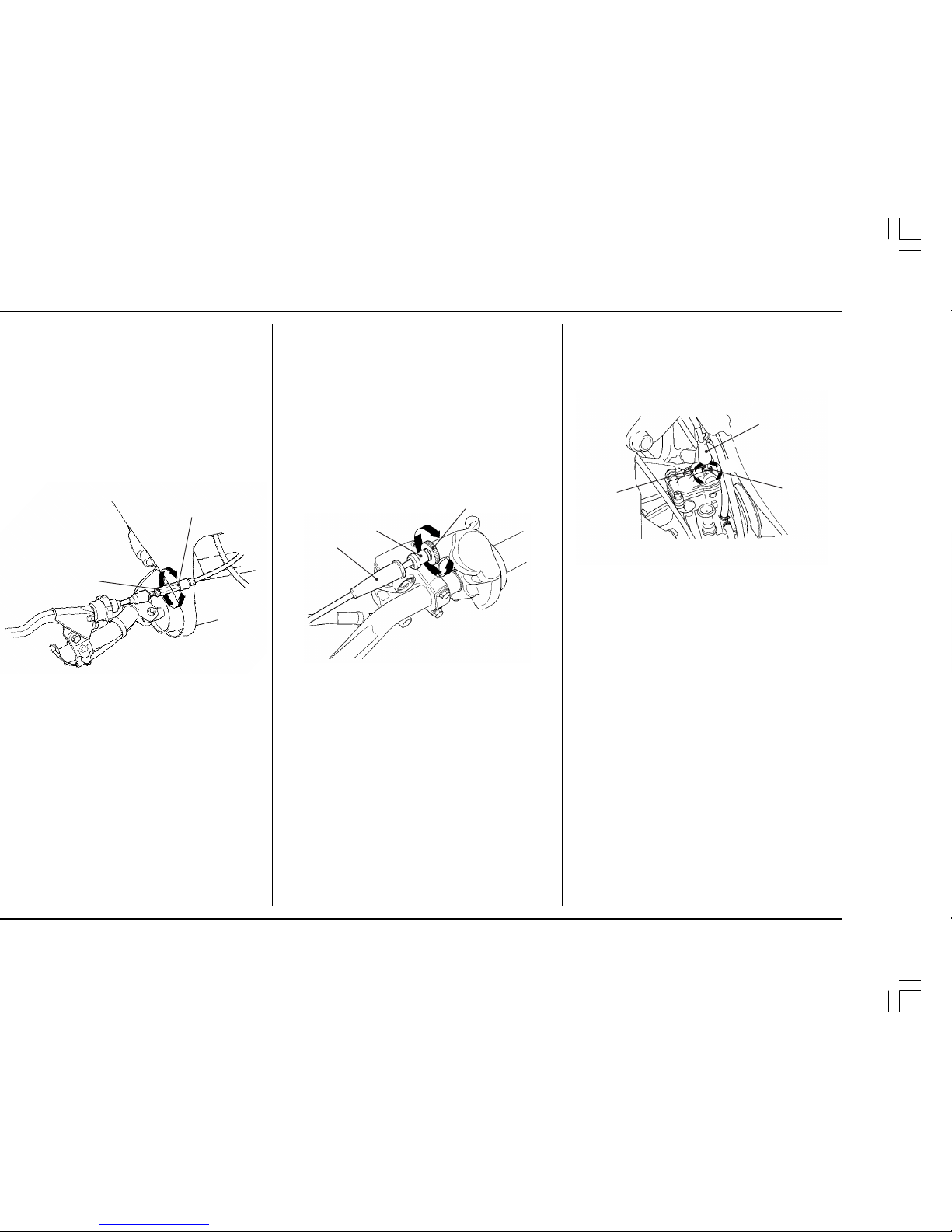
2. To make major adjustments, loosen the lock nut.
Turn the adjuster in direction C to increase free play,
and in direction D to decrease free play.
Tighten the lock nut.
3. Operate the throttle grip to ensure that it functions
smoothly and returns completely.
(1) DUST COVER (2) LOCK NUT
(3) ADJUSTER (C) INCREASE
(D) DECREASE
Throttle Grip
Standard throttle grip free play is approximately
1/8 — 3/16 in (3 — 5 mm) of grip rotation.
1. Minor adjustment is made with the upper adjuster.
Remove the dust cover and loosen the lock nut.
Turning the adjuster in direction A will increase free
play and turning it in direction B will decrease free
play. Tighten the lock nut and reinstall the dust
cover after adjustment.
If the adjuster is threaded out near its limit or the
correct free play cannot be reached, turn the
adjuster all the way in and back out one turn.
Tighten the lock nut, install the dust cover and make
the adjustment with the carburetor top adjuster.
(1) DUST COVER (2) LOCK NUT
(3) UPPER ADJUSTER (A) DECREASE (B) INCREASE
1
3
2
B
AA
cable adjuster.
Loosen the lock nut and turn the adjuster. Turning
the adjuster in direction C will increase free play and
turning it in direction D will decrease free play.
Tighten the lock nut after adjusting.
without slipping or dragging.
clutch does not operate correctly, see pages 23 —
24, refer to the Honda Service Manual, or see your
authorized Honda dealer for clutch disassembly
and wear inspection.
7
HONDA O/M ’04 CR250R (E) 31KSK6000 00X31-KSK-6000
3
1
2
B
A
1
1
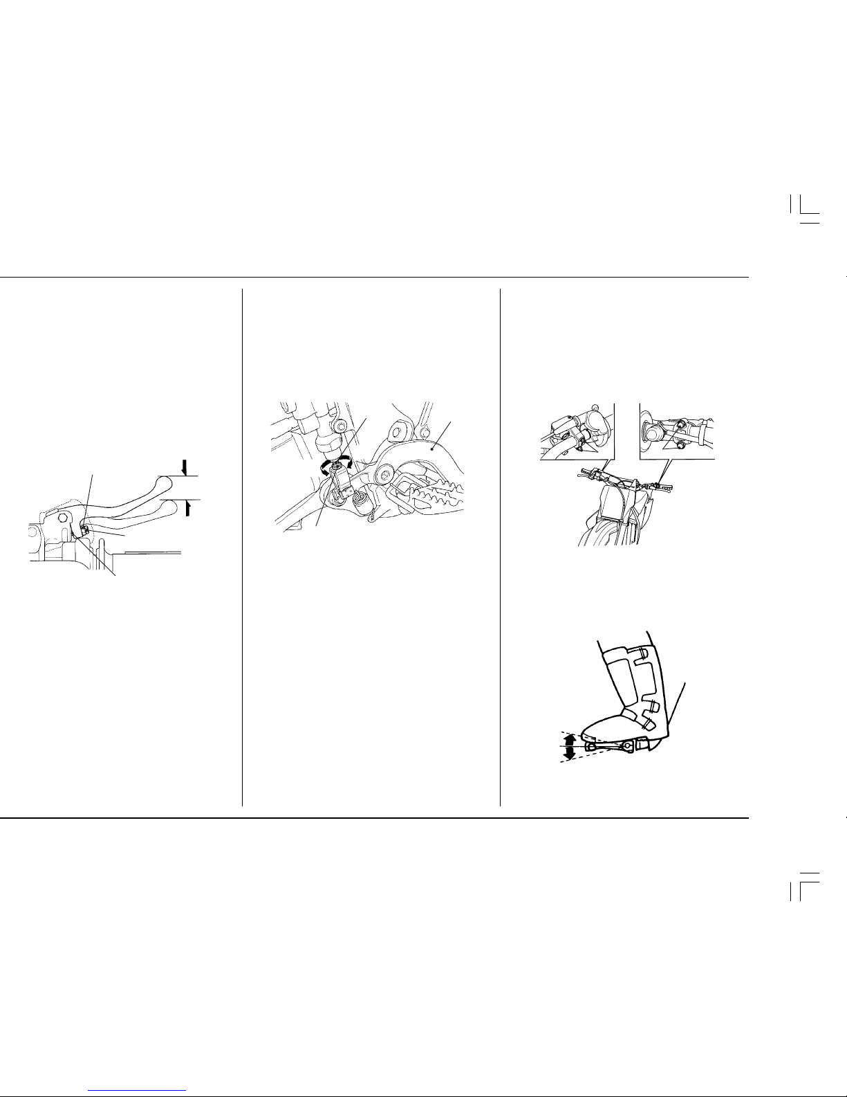
ADJUSTMENT FOR PERSONAL FIT
Control Positioning
• Position the control levers so that control use is
comfortable when both seated and standing.
• Adjust control lever mounting bolt torque so that
the levers will rotate on the handlebar in a fall,
rather than bending or breaking. Apply Honda
Thread Lock or an equivalent to the threads of these
bolts prior to adjustment to help ensure the correct
torque is retained. Tighten the top bolts first.
(1) CONTROL LEVER MOUNT BOLTS
• Position the shifter and brake pedal so that they are
close to your boot for rapid access, but not so close
that either is depressed when sitting or standing
comfortably on the bike.
Brake Pedal Height
The brake pedal height should be approximately level
with the right footpeg.
To adjust the rear brake pedal height:
1. Loosen the lock nut and turn the adjusting bolt in
direction A to raise the pedal, or in direction B to
lower it.
2. Tighten the lock nut at the desired pedal height.
(1) REAR BRAKE PEDAL (2) LOCK NUT
(3) ADJUSTING BOLT
(A) RAISE THE PEDAL HEIGHT
(B) LOWER THE PEDAL HEIGHT
2
1
3
Apply grease to the contacting faces of the adjuster
and piston.
LESS
THAN
0.8 in
(20 mm)
8
HONDA O/M ’04 CR250R (E) 31KSK6000 00X31-KSK-6000
Additional Individualized Adjustments
• Initial suspension adjustments should be performed
after a minimum of two hours of easy break-in time.
Complete information on suspension adjustment is
given in the Suspension Adjustment section.
• Optional front and rear suspension springs (front:
stiffer, rear: stiffer and softer) are available to tailor
your CR specifically for your weight, riding style
and course conditions. Follow the instructions given
in the rear suspension sag setting section of Suspension Adjustment to determine if your combined
rider and sprung machine weight (rider fully dressed
for competition and machine coolant, oil and fuel
levels ready for competition) requires an optional
stiffer or softer rear spring. The use of the stiffer rear
spring may need to be balanced by the use of the
stiffer front spring.
• In order to further fine tune your CR for specific
course terrain and conditions, there is a choice of
both higher and lower final drive ratios with two
optional aluminum driven sprockets. For muddy or
sandy courses, there is a more durable steel driven
sprocket with the standard number of teeth. Like
the optional seats and springs, these sprockets are
listed in the optional parts section of this manual.
and operating the controls are comfortable while
both seated and standing, while riding straight
ahead and turning. Tighten the forward bolts first.
dlebar position may be moved 3 mm forward or
backward. Refer to the Service Manual for installation instractions. Be sure to check the control cable
and wiring harness routing after adjustment.
better suit your particular shoulder width and riding
preference. Think this through carefully and cut off
just a small amount at a time from both sides
equally. It is obviously much easier to make the
handlebar narrower than it is to add material.
irregularities or roughness after sawing the handlebar.
or rearward sweep dimensions, will provide further
adjustment to riding position and may better suit
your particular body size or riding style. Each of the
ergonomic dimensions of the machine were determined to suit the greatest possible number of
riders based on an average size rider.
9
HONDA O/M ’04 CR250R (E) 31KSK6000 00X31-KSK-6000
English
85.5 in
32.4 in
49.7 in
58.3 in
37.4 in
17.2 in
13.3 in
213 lb
Metric
2,180 mm
1,263 mm
1,263 mm
1,482 mm
950 mm
436 mm
339 mm
96.5 kg
Twin tube
Telescopic fork,
travel 11.1 in (281 mm)
stroke 12.4 in (315 mm)
Pro-link,
travel 12.4 in (314 mm)
80/100 — 21 51M
15 (100, 1.0)
110/90 — 19 62M
15 (100, 1.0)
Single disc brake
51.8 in
2
(334.5 cm2)
Single disc brake
60.6 in
2
(391.1 cm2)
English Metric
Liquid cooled, 2-stroke
Single 9° inclined from
vertical
66.4 × 72.0
mm
249.3 cm
3
2.61 × 2.83
in
15.2 cu-in
8.6 : 1
22 US oz
23 lmp oz
650 cm
3
Item
Drive train
Final reduction
Gear shift pattern
Electrical
Ignition
Starting system
Spark plug: Standard
Optional
3.846
Left foot-operated return
system 1-N-2-3-4-5
CDI
Kickstarter
NGK
BR8EG
DENSO
W24ESR-V
NGK
BR8EV
DENSO
W24ESR-G
English
Metric
24 US oz
25 lmp oz
700 cm
3
Piston valve
TMX11A
#420
6CHY12-82
2nd groove
#32.5
1 1/2 turns out
Item
Engine
Type
Cylinder arrangement
Bore and stroke
Displacement
Compression ratio
Transmission oil
capacity draining
at disassembly
Carburetor
Type
Identification number
Main jet (standard)
Jet needle (standard)
Needle clip position
(standard)
Slow jet (standard)
Air screw opening
Float level
Drive train
Clutch type
Transmission
Primary reduction
Gear ratio I
Gear ratio II
Gear ratio III
Gear ratio IV
Gear ratio V
Wet, multi-plate type
5-speed, constant mesh
3.000
1.800
1.470
1.210
1.000
0.869
7.5 mm
0.47 in
Item
Dimension
Overall length
Overall width
Overall height
Wheelbase
Seat height
Footpeg height
Ground clearance
Dry weight
Frame
Type
F. suspension
R. suspension
F. tire size, pressure
psi (kPa, kgf/cm
2
)
R. tire size, pressure
psi (kPa, kgf/cm
2
)
F. brake, swept area
R. brake, swept area
Fuel capacity
Caster angle
Trail length
Fork oil capacity
(fork tube per leg)
7.7 liter
2.0 US gal
1.7 lmp gal
26°49’
107.3 mm
405 cm
3
4.2 in
13.7 US oz
10
HONDA O/M ’04 CR250R (E) 31KSK6000 00X31-KSK-6000
CARBURETOR
Main jet
(Standard: #420)
Slow jet
(Standard: #32.5)
Remarks
#360 — #480 (in increments
of 10)
#27.5 — #45
(in increments of 2.5)
Jet Needles
Standard needle: 6CHY12-
82
Straight diameter: ø2.730 mm
Remarks
To adjust spring preload.
(two spanners required)
For maintenance
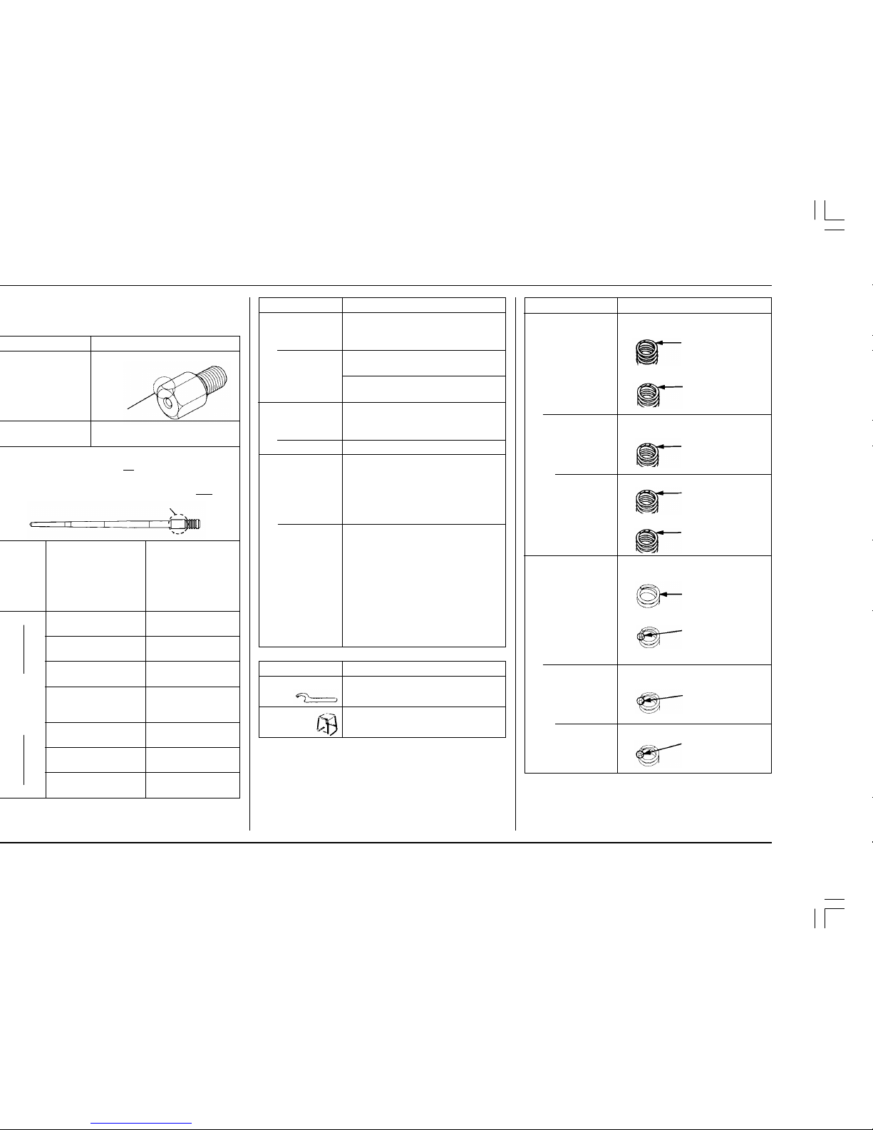
The standard fork spring and shock spring mounted on
the motorcycle when it leaves the factory are not
marked. Before replacing the springs, be sure to mark
them so they can be distinguished from other optional
springs.
Jet needle number
(1/2 clip position
leaner than
standard series.
Leaner only at 1/8
to 3/4 throttle)
Jet needle number
(standard series)
6CHY12-79
ø 2.790 mm
6CHY12-80
ø 2.800 mm
6CHY12-81
ø 2.810 mm
(standard needle)
6CHY12-82
ø 2.820 mm
6CHY12-83
ø 2.830 mm
6CHY12-84
ø 2.840 mm
6CHY12-85
ø 2.850 mm
Front wheel
Standard
Optional
21 inch
Fork height: 0.3 in (7.0 mm)
(align the index groove with the
top of the upper clamp)
20 inch
• wheel assembly
(except brake disk)
• tire tube
• tire flap
• rim lock (bead stopper)
• front tire (90/100-20)
Fork height: 0 in (0 mm)
(align the top of the fork tube with
the top of the upper clamp)
FRAME
Shock spring
Standard
Optional
Softer
Stiffer
Fork spring
Standard
Optional
Softer
Stiffer
General flow characteristics
Leaner Richer
(at1/16 to1/8 throttle)
9
8
6CHY13-79
ø 2.790 mm
6CHY13-80
ø 2.800 mm
6CHY13-81
ø 2.810 mm
6CHY13-82
ø 2.820 mm
6CHY13-83
ø 2.830 mm
6CHY13-84
ø 2.840 mm
6CHY14-85
ø 2.850 mm
FRAME
Driven sprocket
Standard
Optional
Handlebar
lower holder
Standard
Optional
Remarks
< >: Drive chain links
50 Teeth, Aluminum.
<114>
49 Teeth, Aluminum
<114>
47 Teeth, Aluminum
<112>
no offset
3 mm offset
Straight diameter (2.820 mm)
Jetneedle number
420
TOOLS
Pin spanner A
Workstand
Remarks
285.6 lbf/in (5.1 kgf/mm)
No mark
(factory products)
or White
paint
(aftermarket parts)
274.4 lbf/in (4.9 kgf/mm)
Black
paint
296.8 lbf/in (5.3 kgf/mm)
Blue
paint
308.0 lbf/in (5.5 kgf/mm)
Red
paint
24.64 lbf/in (0.44 kgf/mm)
No mark
(factory products)
or
3 scribe marks
(aftermarket parts)
23.52 lbf/in (0.42 kgf/mm)
1 scribe mark
25.76 lbf/in (0.46 kgf/mm)
2 scribe marks

11
HONDA O/M ’04 CR250R (E) 31KSK6000 00X31-KSK-6000
If the Pre-ride and Pre-race inspection are not
performed, severe personal injury or vehicle damage may result.
fouling and high tension cord terminal for
looseness ....................................................... 22
contamination ................................................ 23
condition ........................................................ 35
pressure.......................................................... 36
operation .................................................. 37, 38
lubrication ...................................................... 41
damage or wear............................................. 43
of tension ....................................................... 44
cylinder head nuts, engine mounting bolts,
axle nuts, handlebar holder bolts, fork triple
clamp bolts, drive chain adjuster, drive chain
guide, wire harness connectors, kickstarter
mounting bolt, etc.) ....................................... 45
MAINTENANCE SCHEDULE
Perform the Pre-ride Inspection at each scheduled maintenance period.
I: Inspect and Clean, Adjust, Lubricate or Replace if necessary. C: Clean. R: Replace. L: Lubricate.
FREQUENCY
ITEM
THROTTLE OPERATION
AIR CLEANER
SPARK PLUG
RADIATOR COOLANT
COOLING SYSTEM
CYLINDER HEAD DECARBONIZING
EXHAUST VALVE AND LINKAGE DECARBONIZING
PISTON AND PISTON RINGS
PISTON PIN AND CONNECTING ROD SMALL END
BEARING
REED VALVE ONLY
TRANSMISSION OIL
DRIVE CHAIN
DRIVE CHAIN SLIDERS
DRIVE CHAIN ROLLERS
DRIVE SPROCKET
DRIVEN SPROCKET
BRAKE FLUID
BRAKE PAD WEAR
BRAKE SYSTEM
CLUTCH SYSTEM
CONTROL CABLES
EXPANSION CHAMBER/SILENCER
SUSPENSION
SWINGARM/SHOCK LINKAGE
FORK OIL
NUTS, BOLTS, FASTENERS
WHEELS/TIRES
STEERING HEAD BEARINGS
NOTE
(NOTE 1)
(NOTE 2)
(NOTE 2)
(NOTE 3)
Each race
or about
2.5 hours
I
C
I
I
I
I, L
I
I
I
I
I
I
I
I
I, L
I
I
I
I
Every 3
races
or about
7.5 hours
R
C
C
R
R
R
R
L
R
Every 9
races
or about
22.5 hours
R
R
I
Ref. page
6, 35
23
22
21
21
30
27
30
30, 31
31
20
41 — 42
43
43
41 — 42
41 — 42, 43
39
40
6, 39
5, 24 — 25
44
44
37, 38
16, 38
56, 60
64 — 66
35, 45
36
35
FORK TUBE/SLIDER
DAMPER
This maintenance schedule is based upon average riding condition. Machine subjected to severe use requires more frequent
servicing.
NOTE: 1. Clean after every moto for dusty riding conditions.
2. Replace every 2 years. Replacement requires mechanical skill.
3. Replace after the first break-in ride.
12
HONDA O/M ’04 CR250R (E) 31KSK6000 00X31-KSK-6000
1
1
the optional workstand or equivalent support.
piston pin clips, snap rings, etc. when reassembling.
the larger diameter or inner fasteners, and tighten
them to the specified torque using a crisscross
pattern.
servicing your CR.
disassembling. Lubricate any sliding surface, Orings, and seals before reassembling.
Gasoline or low flash point solvents are highly
flammable or explosive and must never be used for
cleaning parts or the air filter element. Fire or
explosion could result.
lation and operation.
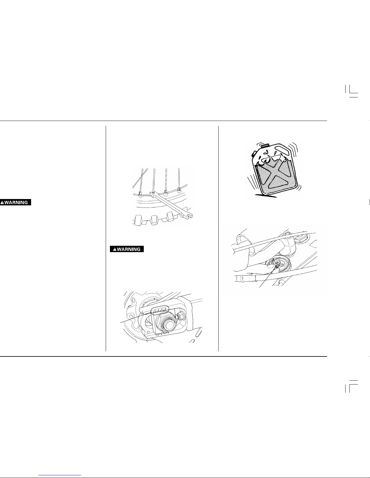
• Be sure the fuel and oil is mixed well by agitating it
thoroughly before pouring pre-mix into the fuel
tank.
• Release the built-up pressure in the fork tubes (in
excess of normal atmospheric pressure: 0 psi)
caused by normal fork action while riding. The front
wheel should be suspended above ground for this
operation.
(1) PRESSURE RELEASE SCREW
BETWEEN MOTO/BETWEEN PRACTICE AND MOTO
MAINTENANCE
• Dirt = wear and weight. Clean accumulated dirt
from under fenders and off of wheels, suspension,
grips, controls and footpegs. A stiff, nylon parts
cleaning brush works well.
• Check tire air pressure.
• Check spoke tension and rim lock nut securely.
• Check sprocket bolt and nut securely.
• Clean chain with a stiff, nylon parts cleaning brush;
lubricate and adjust as necessary.
•
Do not perform maintenance while engine is running. Injury to your fingers or hands may result.
• After adjustment, check that the chain adjuster
index marks are in the same position on each side
to be sure the rear wheel is in proper alignment.
This is especially important for best performance
from the rear disc brake and to extend pad wear.
(1) CHAIN ADJUSTER INDEX MARK
13
HONDA O/M ’04 CR250R (E) 31KSK6000 00X31-KSK-6000
2
1
Take care to prevent catching your fingers between the chain and sprocket.
Take care to prevent catching your fingers between the chain and sprocket.
Some condensation can form within the transmission
cavity as well. This is natural and just one more reason
you should change the transmission oil often.
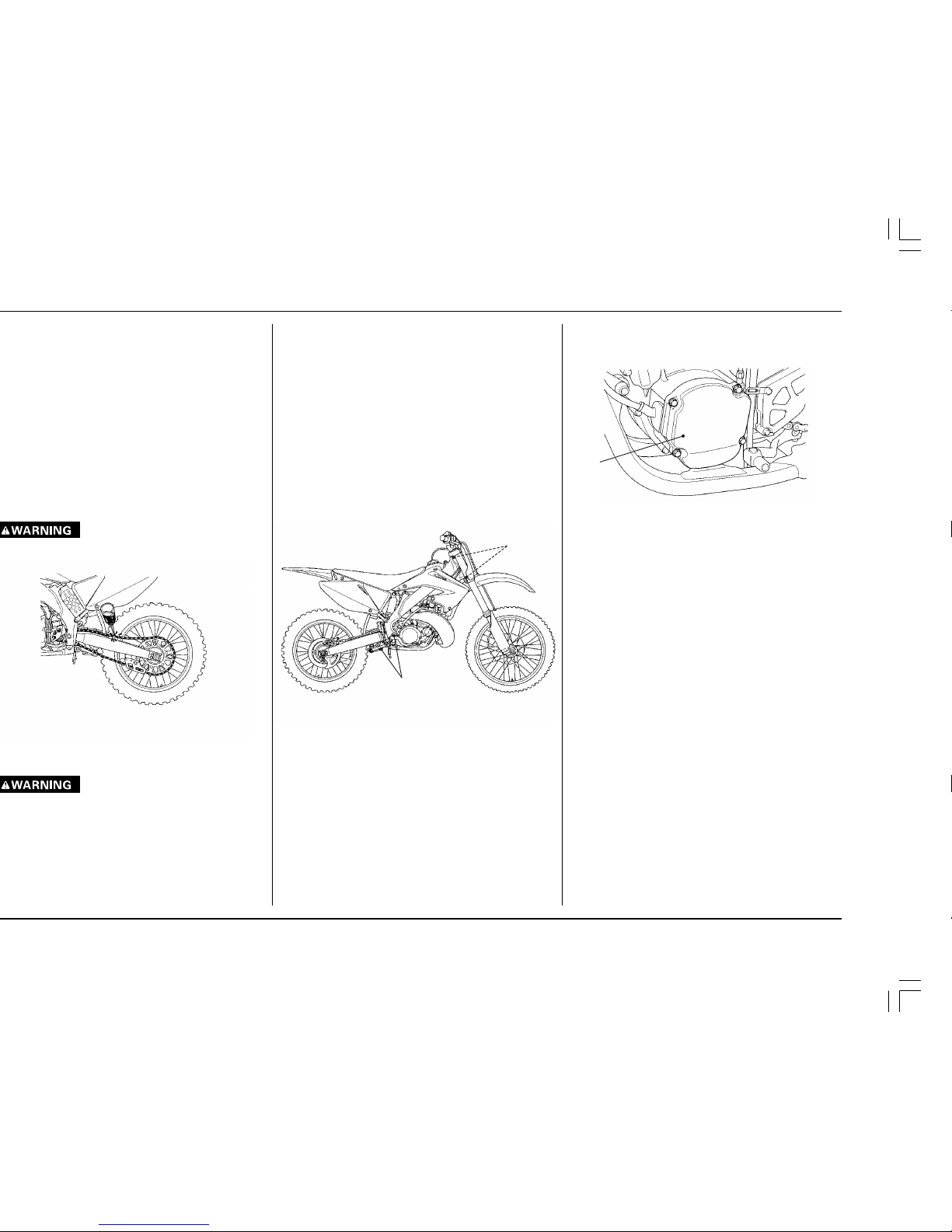
(1) ALTERNATOR COVER
After Cleaning Lubrication
Although you can basically follow the suggestions
given in the Maintenance section under General Maintenance (pages 14—16), there are some things you
should do just after washing your CR to help prevent
rust and corrosion.
Once your CR is clean and dry, you should protect any
bare steel from rusting by applying a light coating of a
rust-inhibitor. Lubricate the drive chain and drive
sprocket after removing and thoroughly cleaning in
solvent. Be sure the chain is wiped clean and is dry
before applying the chain lube.
Follow the suggestions given in the pages of this
manual for lubricating items such as the brake and
clutch lever pivot points and footpeg pivot pins.
A variety of reasonably priced cleaning brushes are
available from variety, drug, food and hardware stores
that are extremely useful in removing dirt from the
many tight contours of your machine.
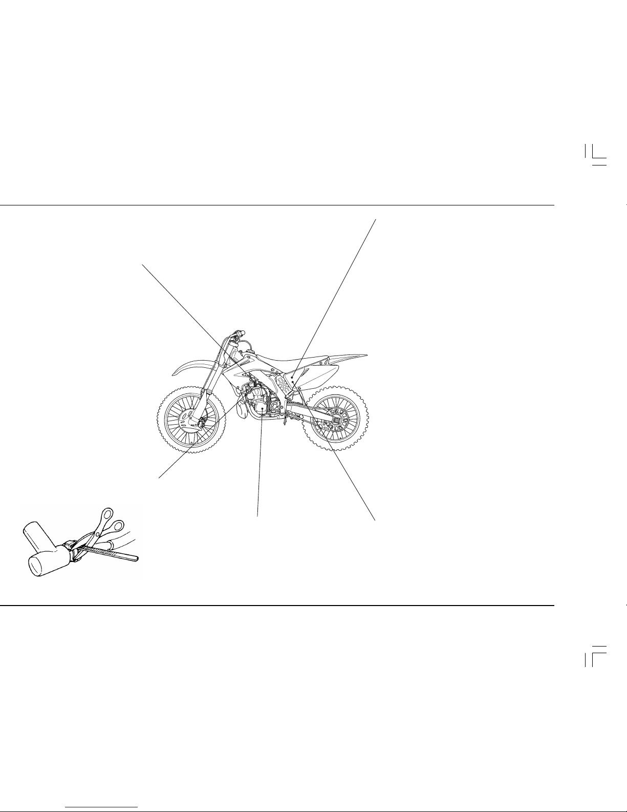
Pressurized Spray Washers
CAUTION:
•
There are some areas on your CR that you should
never directly aim the nozzle of a high pressure
spray washer. It is tempting to let the pressure of
the water remove all the dirt that has accumulated,
but control yourself. The force of the water under
this extreme pressure can penetrate the dust seals
of the suspension pivot points and steering head
bearings—driving dirt inside and needed lubrication out. Avoid spraying water under the seat and
fuel tank and into the airbox as well.
(1) STEERING HEAD BEARINGS
(2) SUSPENSION PIVOT POINTS
Condensation Control
Changes in temperature combined with humidity allow moisture to form in some confined areas on your
CR. The most affected area is the alternator/ignition
cavity in the left side of the crankcases.
Each time you wash your CR you should remove the
alternator cover, wipe out any visible moisture, and
allow the cavity to air dry for at least a couple of hours
before installing the cover. Replace the gasket with a
new one if it is not in good condition before installing
the cover.
1
14
HONDA O/M ’04 CR250R (E) 31KSK6000 00X31-KSK-6000
ignition problems. Refer to the recommendations
elsewhere in this manual for specific types so you
will be sure to use the proper reach and heat range.
Replace periodically as specified in the Maintenance Schedule. (pages 11, 22)
around the spark plug cap to reduce any possibility
of it loosening or of water penetration.
• Air Cleaner: Clean and oil your air cleaner regularly
because the volume of air able to pass through it
has a great effect on performance. Both engine
performance and long term durability may be affected by an air cleaner that has deteriorated and
allows dirt to pass. Inspect the air cleaner closely
each time it’s serviced for evidence of small tears or
seam separation. Keep a spare air cleaner oiled and
ready to install, sealed in a plastic bag. Riding in
dusty conditions may require servicing the air
cleaner or replacing it with a pre-serviced air cleaner
between motos. Be careful not to over oil the air
cleaner. While it is important to oil the air cleaner
thoroughly, over oiling will cause an overall rich
running condition, probably more noticeable off
idle and in low rpm performance. Follow the servicing instructions in the Maintenance section. Use
Pro Honda Foam Filter Oil or an equivalent. Be sure
to grease the air cleaner flange where it contacts the
air cleaner housing. Honda White Lithium Grease,
or an equivalent, is handy for this because any dirt
that penetrates this sealing area will show up clearly.
(page 23)
Use the Honda genuine air cleaner or an equivalent
air cleaner specified for your model.
Using the wrong Honda air cleaner or a non-Honda
air cleaner which is not of equivalent quality may
cause premature engine wear or performance problems.
• Air Box Sealing: Inspect the air cleaner and air
intake tract regularly for signs of deterioration or
dirt penetration.
When removing or resealing the air cleaner housing boot you need to replace the air cleaner housing
boot gasket with a new one.
Refer to the official Honda Service Manual (page 84)
for removal, installation and reseal of the air cleaner
housing boot.
• Transmission Oil: Drain and replace transmission
oil often to ensure the greatest service life of the
transmission and clutch. Frequent changes will
also assure consistent performance of both shifting
and clutch action. (page 20)
15
HONDA O/M ’04 CR250R (E) 31KSK6000 00X31-KSK-6000
• Fuel Filter: Periodically drain the fuel from the tank,
remove and clean the fuel valve/filter. Replace the
fuel valve O-ring if there are any signs of damage or
deterioration. (page 36)
• Fuel Contamination: Periodically drain the float
bowl and inspect the carburetor for contamination
from dirt. (page 48)
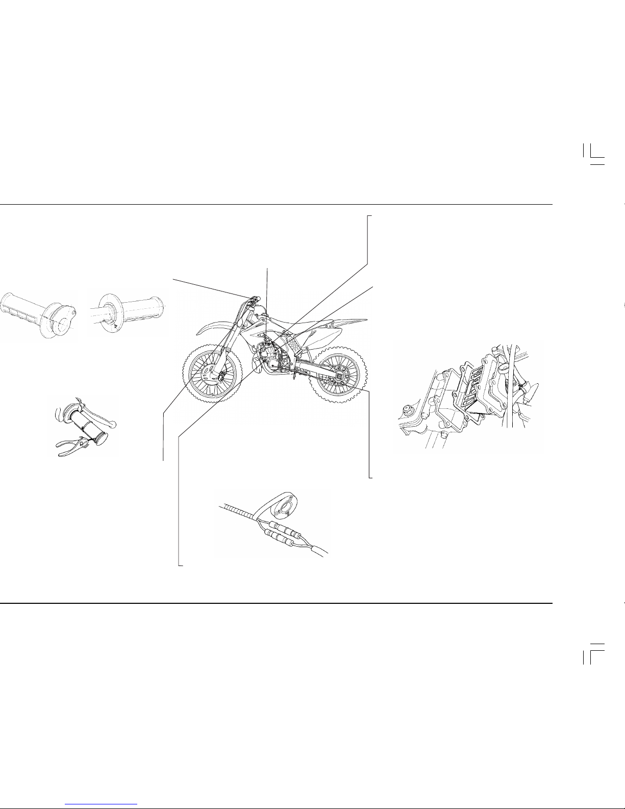
• Inlet Tract Sealing: Air leaks around the carburetor
insulator and reed valve assembly should be cured
by disassembling, cleaning and resealing with new
gaskets and some sealing agent. Be careful not to
overtighten the mounting bolts—this is the most
common cause for leaks here.
• Gaskets: Always use new gaskets when reassembling components.
• Cylinder Removal: Put a little grease on the cylinder mounting dowels to prevent corrosion from
dissimilar metals. The tolerances are quite tight, so
it’s important to keep these dowels absolutely clean.
• Electrical Connectors: Clean electrical connectors
and wrap them with electrical tape to reduce the
possibility of unwanted disconnections, water
shorts or corrosion. Additional corrosion protection is offered by using Honda Dielectric Grease on
all electrical connections.
• Engine Mounting Bolts: Make sure the engine
mounting bolts are tightened to the proper torque
specification. For added peace of mind, remove the
nuts, clean the threads, and apply Honda Thread
Lock or an equivalent prior to torquing the nuts.
• Ignition: Remove the alternator cover and keep it
off for a few hours after each washing to let condensation evaporate. Pull the flywheel rotor every few
rides and clean it and its crankshaft mounting surface, the alternator stator, the ignition pulse generator pickup and the entire ignition cavity thoroughly. The presence of dirt between the ignition
pulse generator and the flywheel makes the ignition control module compensate to maintain the
ignition curve. Cleaning dirt from the ignition side
main seal helps to prevent premature seal wear.
Close inspection of this seal can reveal a leakage
problem before engine damage occurs.
(U.S.A. only) or Honda Bond A when replacing
handgrips.
Throttle grip: Align the index mark on the throttle
grip with the edge of the throttle cable guide.
Left handlebar grip: Align the “∆” mark on the left
handlebar grip with the punch mark on the handlebar.
Refer to the Service Manual for installation instructions.
For added security, you may choose to safety wire
the hand grips to the handlebar and throttle to
prevent the possibility of them loosening. Position
the twisted wire ends away from your palms and be
sure to bend the wire ends well into the grip rubber
so they will not snag your glove.
few rides, clean the inside of the drum and the
handlebar thoroughly, and apply a light coating of
silicone lubricant. Inspect the cable carefully for
kinks or other damage that may restrict throttle
control in anyway. Move the handlebar from lock to
lock to be sure there is no cable interference. Check
to be sure the top of the carburetor is screwed on
tight. Make certain the throttle operation is perfect
after servicing and inspecting.
16
HONDA O/M ’04 CR250R (E) 31KSK6000 00X31-KSK-6000
• Brake Fluid Replacement: Replace the hydraulic
fluid in the brake system every two years.
• Water Pump Inspection Hole: After every race, check
the inspection hole, located just below the water
pump cover on the right crankcase cover. Clean
away any clogged dirt or sand, if necessary. Look
for coolant or oil leakage. Leaking coolant indicates
a worn or damaged water seal. Leaking oil indicates
a bad transmission oil seal. If replacement is necessary, both seals should be replaced.
• Brake Caliper Inspection: Be sure both front and
rear calipers are able to move freely on the caliper
bracket pins. Check pad thickness periodically and
replace when minimum thickness is reached.
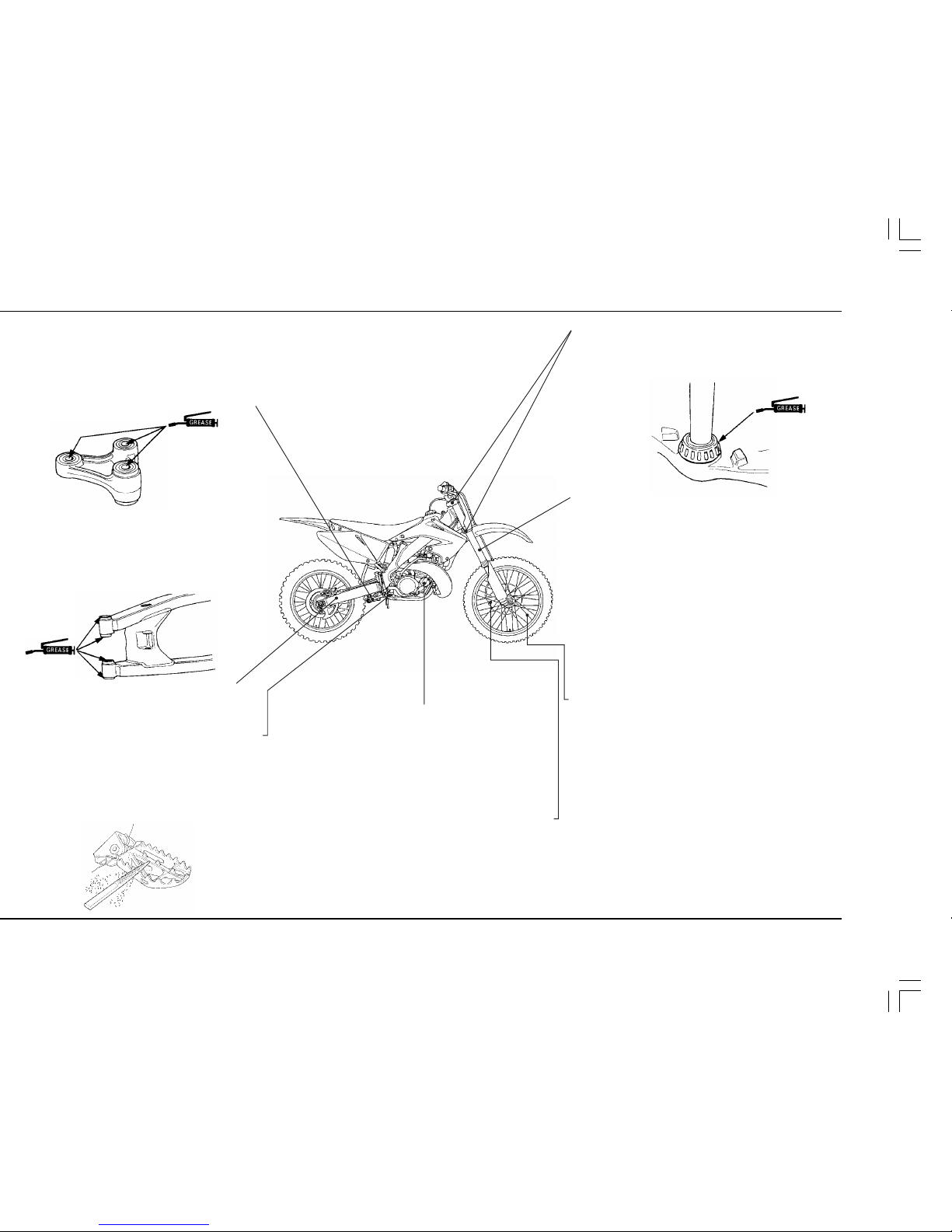
clean, inspect and lubricate all pivot bearings after
each 7.5 hours of running time in order to maintain
proper suspension performance and minimize
component wear. Use Honda Moly 60 Paste (U.S.A.
only) or molybdenum disulfide paste (containing
more than 40% molybdenum disulfide additive).
lubricate when servicing suspension linkage pivots. Be sure all of the suspension pivot seals are in
good condition. Use Honda Moly 60 Paste (U.S.A.
only) or molybdenum disulfide paste (containing
more than 40% molybdenum disulfide additive).
repair a damaged swingarm. Welding will weaken
the swingarm.
filing the grooves between the teeth with a triangular-shaped file. Be aware that filing them too sharp
will reduce boot sole lifespan. Sharpen only the
points of the teeth. Filing the grooves deeper will
weaken the footpegs. Be sure the pegs are free to
pivot freely and that the pivot pin retaining cotter
pins are in good condition.
• Steering Head Bearings: Periodically clean, inspect
and regrease the steering head bearings—especially if wet, muddy or extremely dusty courses are
encountered often.
• Fork Oil/Performance: Disassemble, clean and inspect the fork and replace the oil regularly. Contamination due to the tiny metal particles produced
from the normal action of the fork, as well as normal
oil breakdown, will deteriorate the performance of
the suspension. Refer to the Honda Service Manual.
Use only Pro Honda HP Fork Oil 5W or equivalent
which contains special additives to assure maximum performance of your CR’s front suspension.
• Frame: Because your CR is a high-performance
machine, the frame should not be overlooked as
part of your overall competition maintenance program. Periodically inspect the frame closely for
possible cracking or other damage. It makes good
racing sense.
• Spokes: Check spoke tension frequently between
the first few rides. As the spokes, nipples and rim
contact points seat-in, the spokes may need to be
retightened. Once past this initial seating-in period,
the spokes should hold their tension. Still, be sure
your race maintenance program includes checking
spoke tension and overall wheel condition on a
regular basis. (page 36)
• Nuts, Bolts, Etc.: Application of a thread locking
agent to essential fasteners offers added assurance
and security. Remove the nuts, clean the threads of
both the nuts and bolts, apply Honda Thread Lock
or an equivalent and tighten to the specified torque.
17
HONDA O/M ’04 CR250R (E) 31KSK6000 00X31-KSK-6000
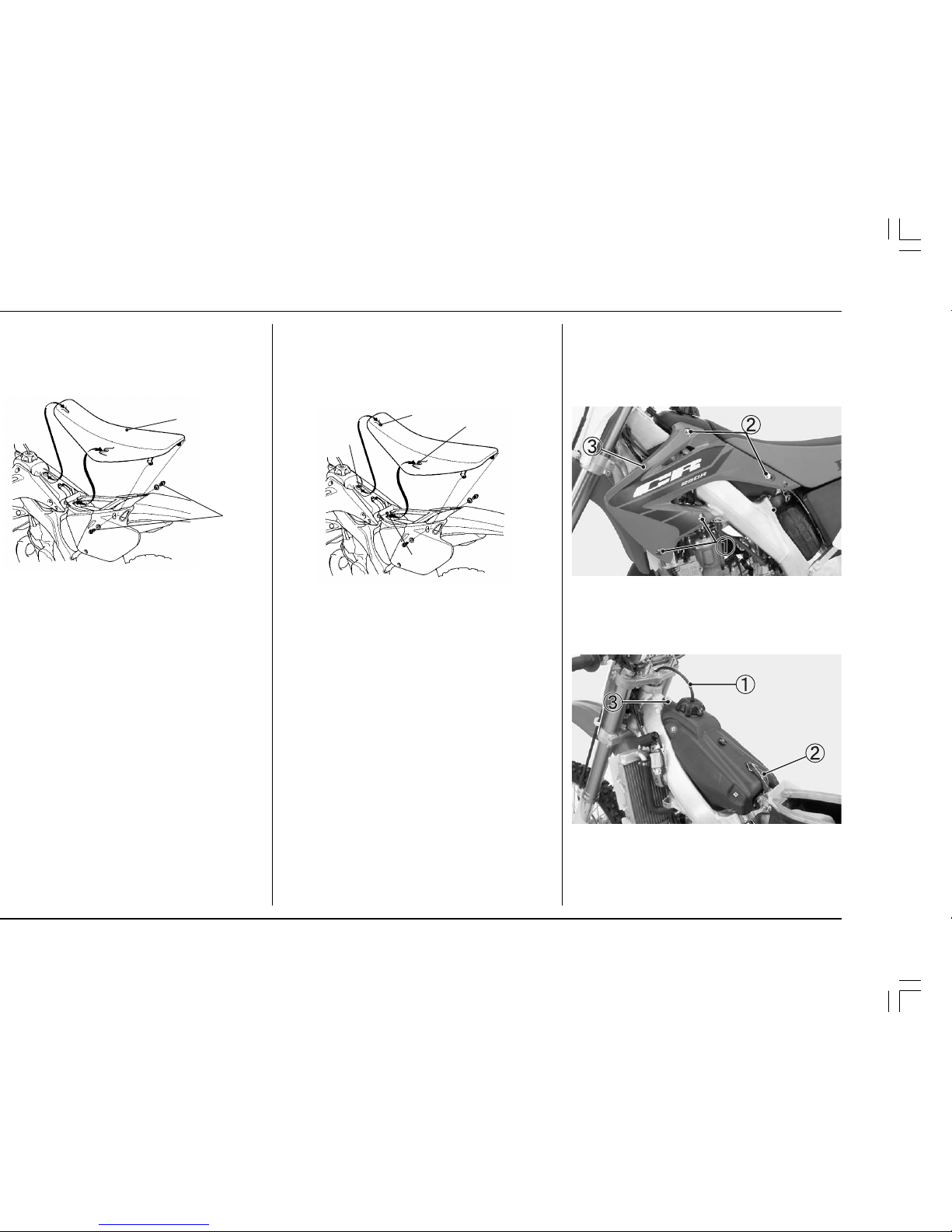
Seat Installation
1. Slide the seat front prong onto the seat bracket and
the seat rear prong onto the tabs by pushing down
and forward on the seat in each of these areas.
2. Install the collars and tighten the seat bolts.
TORQUE: 20 lbf
•ft (27 N•m, 2.7 kgf•m)
(1) SEAT FRONT PRONG (2) SEAT BRACKET
(3) SEAT REAR PRONG (4) TABS
FUEL TANK
Fuel Tank Removal
1. Turn the fuel valve OFF.
2. Remove the seat (this page).
3. Remove the shroud A bolts and collars.
4. Remove the shroud B bolts, collars and shrouds.
(1) SHROUD A BOLTS/COLLARS
(2) SHROUD B BOLTS/COLLARS (3) SHROUD
5. Pull the breather tube out of the steering stem nut.
6. Unhook and remove the fuel tank band.
7. Remove the fuel tank bolt.
(1) BREATHER TUBE
(2) FUEL TANK BAND
(3) FUEL TANK BOLT
1
2
4
2
1
3
18
HONDA O/M ’04 CR250R (E) 31KSK6000 00X31-KSK-6000
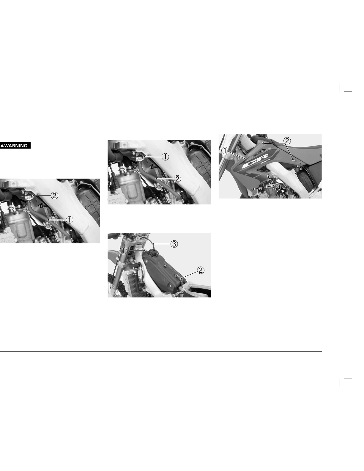
Fuel Tank Installation
1. Install the fuel tank on the frame.
2. Connect the fuel line.
(1) FUEL VALVE (2) FUEL LINE
3. Install the fuel tank bolt.
4. Hook the fuel tank band.
5. Put the breather tube in the steering stem nut.
(1) FUEL TANK BOLT
(2) FUEL TANK BAND
(3) BREATHER TUBE
The fuel line leading to the carburetor must be disconnected, not the fuel line leading to the fuel tank.
Gasoline is extremely flammable and is explosive
under certain conditions. Perform this operation in
a well-ventilated area with the engine stopped. Do
not smoke or allow flames or sparks in the area
where gasoline is drained or stored and where the
fuel tank is refueled.
6. Install the shrouds, collars and shroud B bolts.
7. Install the collars and shroud A bolts.
(1) SHROUD
(2) SHROUD B BOLTS/COLLARS
(3) SHROUD A BOLTS/COLLARS
8. Install the seat (page 17).
19
HONDA O/M ’04 CR250R (E) 31KSK6000 00X31-KSK-6000
1
1
2
1
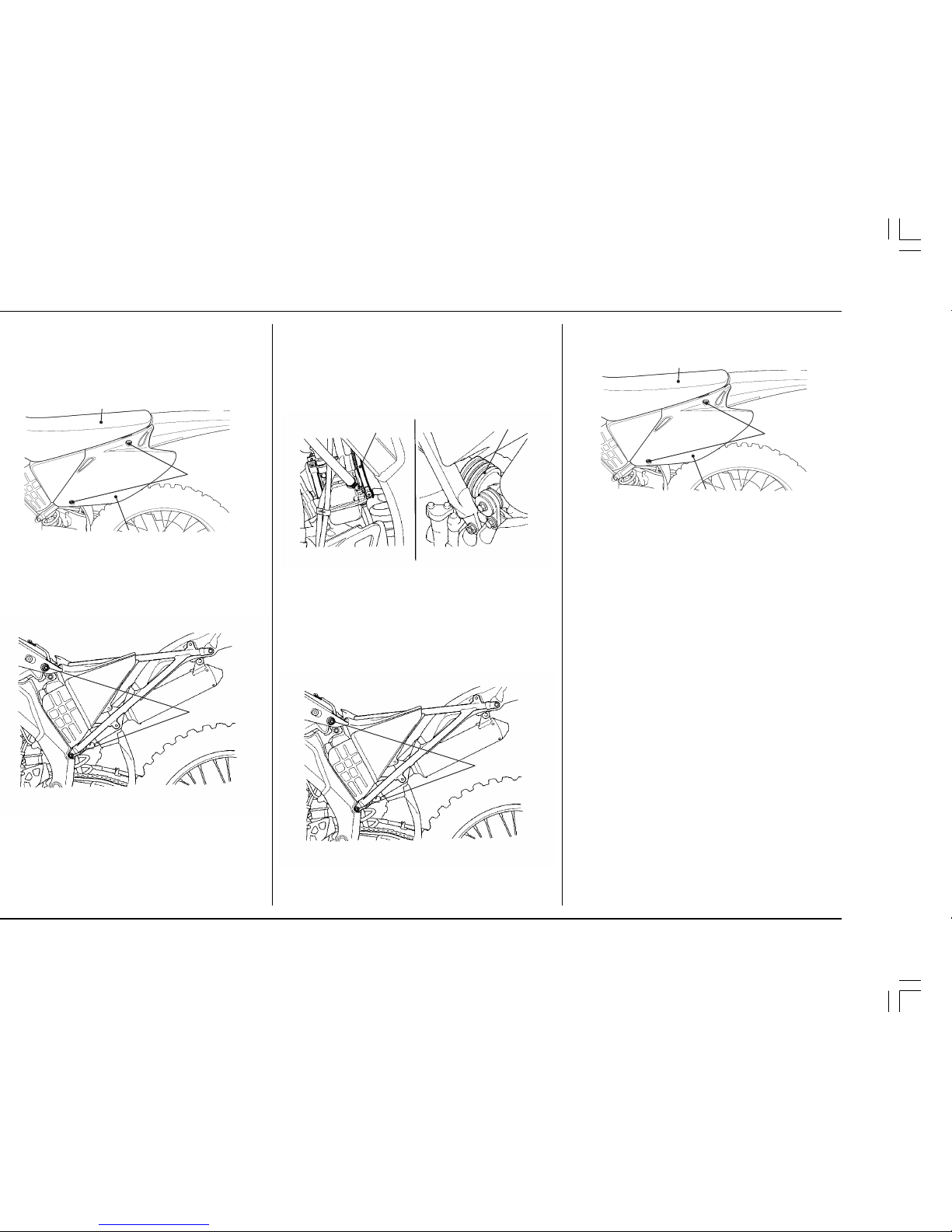
Subframe Installation
1. Loosely attach the upper and lower ends of the
subframe to the mainframe while connecting the
expansion chamber to the muffler with the sealing
rubber and air filter connecting tube to the
carburetor.
2. Tighten the screw on the connecting tube clamp.
(1) SEALING RUBBER
(2) CONNECTING TUBE CLAMP
3. Align the subframe with the rear wheel and tighten
the three subframe mounting bolts.
TORQUE:
Upper: 22 lbf•ft (30 N•m, 3.1 kgf•m)
Lower: 22 lbf•ft (30 N•m, 3.1 kgf•m)
(1) SUB FRAME MOUNTING BOLTS
collars.
clamp.
backward.
4. Install the side covers, side cover bolts and collars.
5. Install the seat (page 17).
(1) SIDE COVER
(2) SIDE COVER BOLTS/COLLARS
(3) SEAT
2
1
3
2
3
1
20
HONDA O/M ’04 CR250R (E) 31KSK6000 00X31-KSK-6000
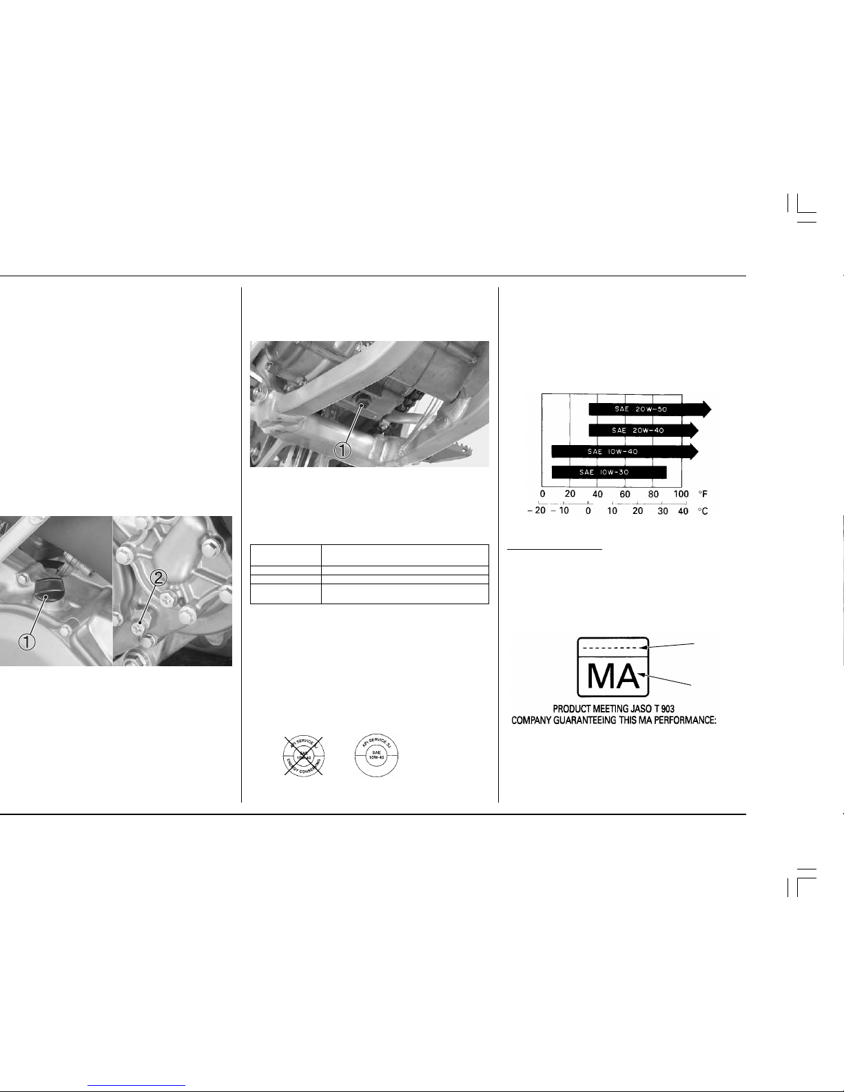
6. Add the recommended oil.
Capacity: 22 US oz (650 cm2, 23 lmp oz) at oil
change
7. Check the oil level by following the steps in Inspecting and Adding Transmission Oil.
(1) OIL DRAIN BOLT
Recommended transmission oil
Use Pro Honda HP Trans Oil, Pro Honda GN4 or HP4
(without molybdenum additives) 4–stroke oil, or an
equivalent.*
4–stroke oil performance
* Suggested oils are equal in performance to SJ oils
that are not labeled as energy conserving on the
circular API service label.
• Your CR does not need oil additives. Use recom-
mended oil.
• Do not use oils with graphite or molybdenum addi-
tives. They may adversely affect clutch operation.
• Do not use API SH or higher oils displaying a circular
API “energy conserving” label on the container. They
may affect lubrication and clutch performance.
NOT RECOMMENDED OK
allow the oil to properly distribute itself in the clutch
and transmission.
surface.
right crankcase cover. A small amount of oil should
flow out of the check bolt hole. Allow any excess oil
to flow out of the check bolt hole.
slowly through the oil filler hole until oil starts to
flow out of the check bolt hole. Install the oil check
bolt and filler cap.
the oil check bolt and filler cap securely.
TORQUE: 7 lbf
•ft (10 N•m, 1.0 kgf•m)
surface.
cover.
oil. Then remove the drain bolt.
drain bolt with a new sealing washer.
TORQUE: 22 lbf
•ft (29 N•m, 3.0 kgf•m)
CAUTION:
•
Oil is a major factor affecting the performance and
service life of the transmission and clutch.
Nondetergent, vegetable, or caster based racing
oils are not recommended.
Other viscosities shown in the chart below may be used
when the average temperature in your riding area is
within the indicated range.
JASO T 903 standard
The JASO T 903 standard is an index to choose engine
oils for 4-stroke motorcycle engines.
There are two classes: MA and MB.
Oil conforming to the standard has the following classification on the oil container.
(1) code number of the sales company of the oil
(2) oil classification
API classification
viscosity (weight)
JASO T 903
others
SG or higher except oils labeled as energy
conserving on the circular API service label
SAE 10W–40
MA
without friction modifiers as molybdenum additives
(1)
(2)
21
HONDA O/M ’04 CR250R (E) 31KSK6000 00X31-KSK-6000
Hard water or salt water is harmful to aluminum.
The factory provides a 50/50 mix of anti-freeze and
water in your CR. This mixture is recommended for
most operating temperatures and provides good
corrosion protection. A higher concentration of
anti-freeze decreases the cooling system performance and is recommended only when additional
protection against freezing is needed. Using less
than 40% anti-freeze will not provide proper cooling or corrosion protection.
Using coolant with silicate inhibitors may cause
premature wear of water pump seals or blockage
of radiator passages. Using tap water may cause
engine damage.
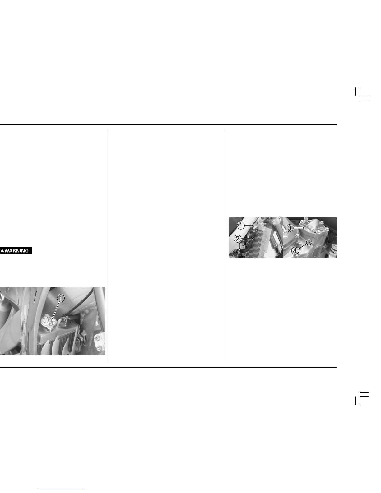
Never remove the radiator cap when the engine is
hot. The coolant is under pressure and severe
scalding could result.
check coolant level. The coolant level is correct
when it is at the bottom of the radiator filler neck.
2. Add coolant up to the filler neck if the level is low.
NOTE:
• Inspect the coolant level before each outing. A
coolant loss of 0.7 — 2.0 U.S. oz (20 — 60 cc, 0.7 —
2.1 lmp, oz) through the over flow tube is normal. If
coolant loss is more than this, inspect the cooling
system.
Capacity: 1.22 US qt (1.15 liter, 1.01 lmp qt) at
disassembly
1.14 US qt (1.08 liter, 0.95 lmp qt) at
coolant change
3. Install the radiator cap securely.
CAUTION:
•
If the radiator cap is not installed properly, it will
cause excessive coolant loss and may result in
overheating and engine damage.
Cooling system inspection
1. Check the cooling system for leaks (see the Honda
Service Manual for troubleshooting of leaks).
2. Check water hoses for cracks, deterioration, and
clamp bands for looseness.
3. Check the radiator mount for looseness.
4. Make sure the overflow tube is connected and not
clogged.
5. Check the radiator fins for clogging.
6. Check the water leakage check hole below the water
pump for leakage. Make sure the hole remains
open. If water leaks through the check hole, the
water pump seal is damaged. If oil leaks through the
check hole, the transmission oil seal is damaged.
See the Honda Service Manual or consult your
authorized Honda dealer for replacing the water
pump seal or the transmission oil seal. Both seals
should be replaced at the same time.
(1) OVERFLOW TUBE (3) WATER PUMP
(2) RADIATOR HOSE (4) WATER LEAKAGE
CHECK HOLE
22
HONDA O/M ’04 CR250R (E) 31KSK6000 00X31-KSK-6000
The use of a spark plug of the incorrect reach or
heat range can cause engine damage. The use of a
non-resistor spark plug may cause ignition problems.
adjust by carefully bending the side electrode.
The recommended spark plug gap is:
0.020 — 0.024 in (0.5 — 0.6 mm).
for damage, and the insulator for cracks.
up to speed on a straightaway. Push the engine stop
button and disengage the clutch by pulling the lever
in.
Coast to a stop, then remove and inspect the spark
plug. The porcelain insulator around the center
electrode should appear tan or medium gray.
NOTE:
• If you’re using a new plug, ride for at least ten
minutes before taking a plug reading; a brand-new
plug will not color initially.
If the electrodes appear burnt, or the insulator is white
or light gray (lean) or the electrodes and insulator are
black or fouled (rich), there is a problem elsewhere
(page 47). Check the fuel/oil mixture, carburetor and
fuel system, and ignition timing.
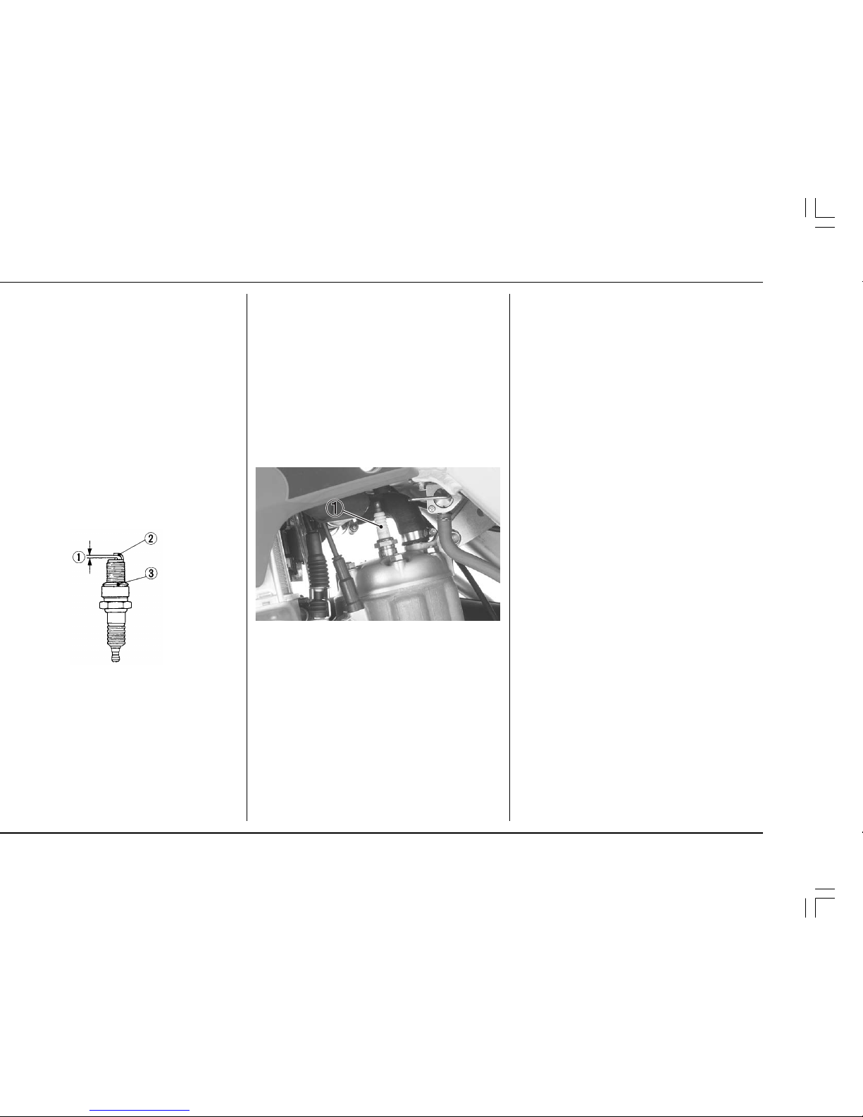
4. Install the spark plug by hand until finger tight, then
tighten with a spark plug wrench until the sealing
gasket is compressed (1/2 turn to compress a new
spark plug gasket, 1/8—1/4 turn to compress a spark
plug with a used gasket).
(1) SPARK PLUG
IGNITION
A CDI (Capacitive Discharge lgnition) system is used on
this motorcycle; consequently, routine ignition timing
adjustment is unnecessary. If you want to check the
ignition timing, refer to the Honda Service Manual.
23
HONDA O/M ’04 CR250R (E) 31KSK6000 00X31-KSK-6000
2
1
5
3
4
1
5
3
2
4
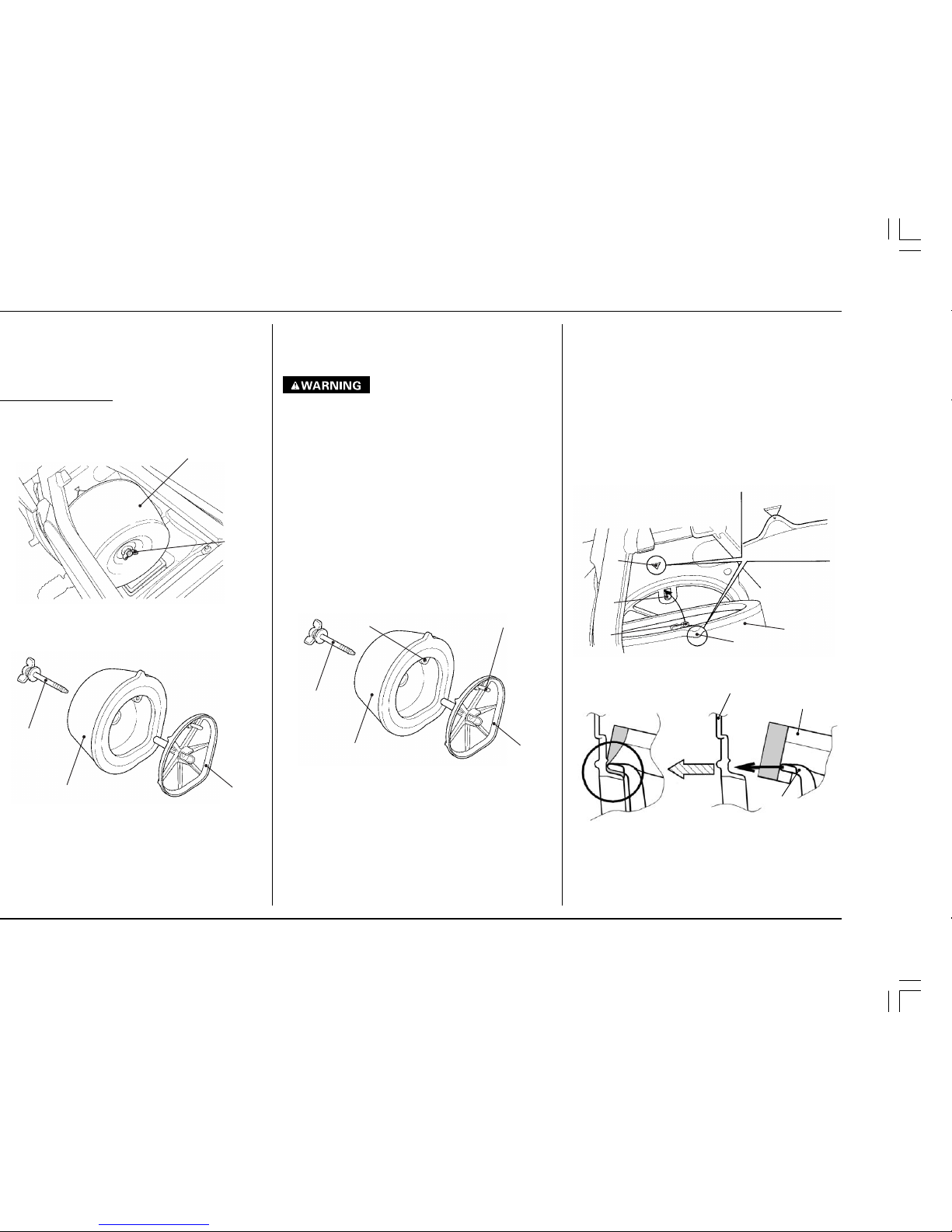
10. Insert the pin in the air cleaner housing hole and
install the assembly into the air cleaner housing
while aligning the tab on the air cleaner and the
reference mark on the air cleaner housing. Tighten
the retaining bolt securely.
Carefully position the sealing flange of the element
to prevent dirt instruction.
11. Reinstall the seat, making sure it is securely attached.
CAUTION:
•
If the air cleaner assembly is not installed correctly,
dirt and dust may enter the engine resulting in
rapid wear of the piston rings and cylinder.
(1) AIR CLEANER (2) PIN
(3) AIR CLEANER HOUSING HOLE
(4) TAB (5) REFERENCE MARK
(6) AIR CLEANER HOUSING
(7) AIR CLEANER HOLDER
1
2
1
2
3
5. Wash the air cleaner in clean non-flammable cleaning solvent. Then wash in hot, soapy water, rinse
well, and allow to dry thoroughly.
6. Clean the inside of the air cleaner housing.
•
Never use gasoline or low flash point solvents for
cleaning the air cleaner. A fire or explosion could
result.
NOTE:
• The air cleaner is made in two pieces: inner and
outer which can’t be separated.
7. Allow the air cleaner to dry thoroughly. After drying, soak the air cleaner in clean Pro Honda Foam
Filter Oil or an equivalent air cleaner oil.
Apply air cleaner oil to the entire surface, inner and
outer, and rub it with both hands to saturate the air
cleaner with oil. Squeeze out excess oil.
8. Apply a thin coat of white lithium grease to the
sealing surface.
9. Assemble the air cleaner and holder.
Insert the pin through the hole, and the air cleaner
retaining bolt through the assembly.
(1) AIR CLEANER (2) AIR CLEANER HOLDER
(3) PIN (4) HOLE
(5) AIR CLEANER RETAINING BOLT
1
6
7
24
HONDA O/M ’04 CR250R (E) 31KSK6000 00X31-KSK-6000
Lubricate the clutch lever pivot or clutch cable if
operation is not smooth.
damage.
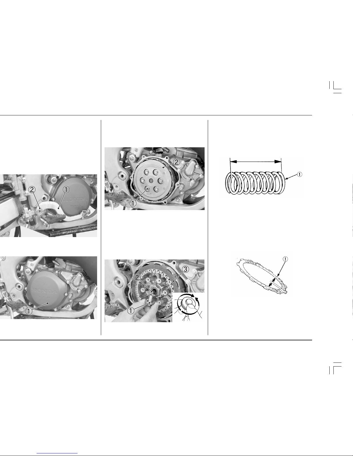
Remove the six clutch spring bolts and clutch springs.
NOTE:
• Loosen the bolts in a crisscross pattern in 2 or 3
progressive steps.
Remove the clutch pressure plate.
(1) CLUTCH SPRING BOLTS
(2) CLUTCH PRESSURE PLATE
Remove the clutch lifter and clutch lifter rod.
Remove the eight clutch discs and seven clutch plates.
NOTE:
• Turn the lifter bearing plate of the clutch lifter
bearing with your finger. The bearing plate should
turn smoothly and quietly. Discard the clutch lifter
if the bearing plate does not turn smoothly.
(1) CLUTCH LIFTER (3) CLUTCH PLATES AND
(2) CLUTCH LIFTER ROD DISCS
Clutch Spring
Measure each clutch spring’s free length.
SERVICE LIMIT: 1.76 in (44.7 mm)
Replace the clutch springs as a set if any one of them is
beyond the service limit or if the clutch plates have
been burnt/heat discolored.
(1) CLUTCH SPRING
Clutch Disc
Replace the clutch discs if they show signs of scoring or
discoloration.
Measure the thickness of each clutch disc.
SERVICE LIMIT: 0.112 in (2.85 mm)
NOTE:
• Replace the clutch discs and clutch plates as an
assembly.
(1) CLUTCH DISC
 Loading...