

Page 1

Honda CGL125 / / NR
OWNER’S MANUAL
Honda Motor Co., Ltd. 2005
Page 2

IMPORTANT INFORMATION
OPERATOR AND PASSENGER
This motorcycle is designed to carry the operator and one passenger.
ON-ROAD USE
This motorcycle is designed to be used only on the road.
READ THIS OWNER’S MANUAL CAREFULLY
Pay special attention to the safety messages that appear throughout the manual. T hese
messages are fully explained in the ‘‘A Few Words About Safety’’ section which appears
before the Contents page.
This manual should be considered a permanent part of the motorcycle and should remain
with the motorcycle when resold.
Page 3
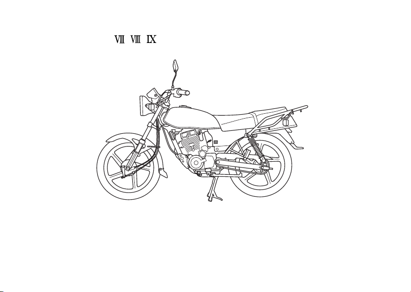
Honda CGL125 / / NR
OWNER’S MANUAL
All information in this publication is based on the lat est production information
available at the time of approval f or printing. Honda Motor Co.,Ltd. reserves the
right to make changes at any time without notice and without incurring any
obligation.
No part of this publication may be reproduced without written permission.
Page 4

WELCOME
The motorcycle presents you a challenge to master the machine, a challenge to adventure.
You ride through the wind, linked to the road by a vehicle that responds to your commands
as no other does. Unlike an automobile, there is no metal cage around you. Like an airplane, a
pre-ride inspection and regular maintenance are essential to your safety. Your reward is
freedom.
To meet the challenges safely, and to enjoy the adventure fully, you should become
thoroughly familiar with this owner’s manual BEFORE YOU RIDE THE MOTORCYCLE.
Asyoureadthismanual,youwillfindinformationthatisprecededbya symbol.This
information is intended to help you avoid damage to your motorcycle, other property, or the
environment.
When service is required, remember that your Honda dealer knows your motorcycle best. If
you have the required mechanical ‘‘know-how’’ and tools, your dealer can supply you with an
official Honda Service Manual to help you perform many maintenance and repair tasks.
Pleasant riding, and thank you for choosing a Honda !
Page 5

The f ollowing code in this manual indicate the country.
The specifications may vary with each locale.
Nigeria
NR
The illustrations herein are based on the type .
Page 6

AFEWWORDSABOUTSAFETY
Your safety, and the saf ety of others, is very important. And operating this motorcycle saf ely
is an important responsibility.
To help you make informed decisions about safety, we have provided operating procedures
and other information on labels and in this manual. This information alerts you to potential
hazards that could hurt you or others.
Of course, it is not practical or possible to warn you about all hazards associated with
operating or maintaining a motorcycle. You must use your own good judgment.
You will f ind important safety information in a variety of forms, including:
Safety Labels
Safety Messages
DANGER, WARNING, CAUTION
These signal words mean:
–– on the motorcycle.
–– preceded by a safety alert symbol and one of three signal words:
or .
Page 7

You WILL be KILLED or SERIOUSLY HURT if you don’t follow
instructions.
You CAN be KILLED or SERIOUSLY HURT if you don’t follow
instructions.
You CAN be HURT if you don’t follow instructions.
Safety Headings
Safety Section
Instruct ions
This entire manual is filled with important safety information –– please read it carefully.
–– such as Important Safety Reminders or Important Safety Precautions.
–– such as Motorcycle Safety.
–– how to use this motorcycle correctly and safely.
Page 8

OPERATION
page page
MOTORCYCLE SAFETY
1
IMPORT ANT SAFETY
1
INFORMATION
2
PROTECTIVE APPAREL
4
LOAD LIMITS AND GUIDELINES
PARTS LOCA TION
8
11
INSTRUMENTS AND
INDICATORS
MAJOR COMPONENTS
15
(Information you need to operate
this motorcycle)
15
SUSPENSION
16
BRAKES
22
CLUTCH
24
FUEL
28
ENGINE OIL
29
TYRES
34
34
35
36
ESSENTIAL INDIVIDUAL
COMPONENTS
IGNITION SWITCH
RIGHT HANDLEBAR CONTROLS
LEFT HANDLEBAR CONTROLS
Page 9

page page
37 42
(Not required for operation)
37
STEERING LOCK
38
SIDE COVERS
40
SEAT
41
ADJUSTMENT
42
44
48
49
50
52
53
54
OPERATIONFEATURES
PRE-RIDE INSPECTION
STARTING THE ENGINE
RUNNING-IN
RIDING
SHIFTINGHEADLIGHT AIM VERTICAL
BRAKING
PARKING
ANTI-THEFT TIPS
Page 10

MAINTENANCE
page
MAINTENANCE
55
55
THE IMPORTANCE OF
MAINTENANCE
56
MAINTENANCE SAFETY
57
SAFETY PRECAUTIONS
58
MAINTENANCE SCHEDULE
61
TOOL KIT
62
SERIAL NUMBERS
63
COLOUR LABEL
64
ENGINE OIL
67
ENGINE OIL STRAINER SCREEN
68
SPARK PLUG
70
VALVE CLEARANCE
72
THROTTLE OPERATION
73
IDLE SPEED
74
AIR CLEANER
76
DRIVE CHAIN
83
FRONT AND REAR SUSPENSION
INSPECTION
84
SIDE STAND
85
WHEEL REMOVAL
91
BRAKE SHOE WEAR
92
BRAKE PAD WEAR
page
BATTERY
93
FUSE REPLACEMENT
97
BRAKELIGHT SWITCH
100
ADJUSTMENT
BULB REPLACEMENT
101
CLEANING
106
STORAGE GUIDE
109
109
STORAGE
111
REMOVAL FROM STORAGE
SPECIFICATIONS
112
Page 11

MOTORCYCLE SAFETY
IMPORTANT SAFETY INFORMATION
Your motorcycle can provide many years of
service and pleasure if you take
responsibility for your own safety and
understand the challenges that you can
meet on the road.
Thereismuchthatyoucandotoprotect
yourself when you ride. You’ll f ind many
helpful recommendations throughout this
manual. Following are a few that we
consider most important.
Always Wear a Helmet
It’s a proven f act: helmets significantly
reduce the number and severity of head
injuries. So always wear an approved
motorcycle helmet and make sure your
passenger does the same. We also
recommend that you wear eye protection,
sturdy boots, gloves, and other protective
gear (page ).
2
−
Make Yourself Easy to See
Some drivers do not see motorcycles
because they are not looking for them. To
make yourself more visible, wear bright
reflective clothing, position yourself so
other drivers can see you, signal bef ore
turning or changing lanes, and use your
horn when it will help others notice you.
Ride Within Your Limits
Pushing the limits is another major cause of
motorcycle accidents. Never ride beyond
your personal abilities or f aster than
conditions warrant. Remember that alcohol,
drugs, fatigue and inattention can
significantly reduce your ability to make
good judgements and ride safely.
1
Page 12
Alcohol and riding don’t mix. Even one
drink can reduce your ability to respond to
changing conditions, and your reaction time
gets worse with every additional drink. So
don’t drink and ride, and don’t let your
friends drink and ride either.
Keep Your Bike in Saf e Condition
For safe riding, it’s important to inspect
your motorcycle before every ride and
perform all recommended maintenance.
Never exceed load limits, and only use
accessories that have been approved by
Honda for this motorcycle. See page for
more details.
2
4
PROTECTIVE APPARELDon’t Drink and Ride
Foryoursafety,westronglyrecommend
that you always wear an approved
motorcycle helmet, eye protection, boots,
gloves, long pants, and a long-sleeved shirt
or jacket whenever you ride. Although
complete protection is not possible, wearing
proper gear can reduce the chance of injury
when you ride.
Following are suggestions to help you
choose proper gear.
Not wearing a helmet increases the
chance of serious injury or death in a
crash.
Be sure you and your passenger
always wear a helmet, eye protection
and other protective apparel when you
ride.
Page 13

Helmets and Eye Protection Additional Riding Gear
Your helmet is your most important piece of
riding gear because it of fers the best
protection against head injuries. A helmet
should fit your head comfortably and
securely. A bright-coloured helmet can
make you more noticeable in traffic, as can
reflective strips.
An open-face helmet offers some protection,
but a f ull-face helmet offers more. Always
wear a face shield or goggles to protect
your eyes and help your vision.
In addition to a helmet and eye protection,
we also recommend:
Sturdy boots with non-slip soles to help
protect your feet and ankles.
Leather gloves to keep your hands warm
and help prevent blisters, cuts, burns and
bruises.
A motorcycle riding suit or jacket f or
comfortaswellasprotection.Brightcoloured and reflective clothing can help
make you more noticeable in traffic. Be
sure to avoid loose clothes that could get
caught on any part of your motorcycle.
3
Page 14
Your motorcycle has been designed to carry
you and one passenger. When you carry a
passenger, you may feel some dif ference
during acceleration and braking. But so long
as you keep your motorcycle wellmaintained, with good tyres and brakes, you
can safely carry loads within the given limits
and guidelines.
LoadingLOAD LIMITS AND GUIDELINES
How much weight you put on your
motorcycle, and how you load it, are
important to your safety. Anytime you ride
with a passenger or cargo you should be
aware of the following information.
However, exceeding the weight limit or
carrying an unbalanced load can seriously
affect your motorcycle’s handling, braking
and stability. Non-Honda accessories,
improper modifications, and poor
maintenance can also reduce your safety
margin.
The f ollowing pages give more specific
information on loading, accessories and
modifications.
4
Overloading or improper loading can
causeacrashandyoucanbe
seriously hurt or killed.
Follow all load limits and other loading
guidelines in this manual.
Page 15

Load Limits
Following are the load limits f or your
motorcycle:
Maximum weight capacity:
153 kg (337 lbs)
Includes the weight of the rider,
passenger, all cargo and all accessories
Maximum rear carrier cargo weight:
3.0 kg (6.6 lbs)
The weight of added accessories will reduce
the maximum cargo weight you can carry.
Loading Guidelines
Your motorcycle is primarily intended f or
transporting you and a passenger. You may
wish to secure a jacket or other small items
to the seat when you are not riding with a
passenger.
If you wish to carry more cargo, check with
your Honda dealer for advice, and be sure
to read the information regarding
accessories on page .
6
Improperly loading your motorcycle can
aff ect its stability and handling. Even if your
motorcycle is properly loaded, you should
ride at reduced speeds whenever carrying
cargo.
Follow these guidelines whenever you carry
a passenger or cargo:
Check that both tyres are properly
inflated.
If you change your normal load, you may
need to adjust the rear suspension (page
15
).
To prevent loose items from creating a
hazard,makesurethatallcargois
securely tied down before you ride away.
Place cargo weight as close to the center
of the motorcycle as possible.
Balance cargo weight evenly on both
sides.
5
Page 16

Accessories and Modif ications Accessories
Modifying your motorcycle or using nonHonda accessories can make your
motorcycle unsafe. Bef ore you consider
making any modifications or adding an
accessory,besuretoreadthefollowing
information.
We strongly recommend that you use only
genuine Honda accessories that have been
specifically designed and tested for your
motorcycle. Because Honda cannot test all
other accessories, you must be personally
responsible for proper selection, installation
and use of non-Honda accessories. Check
with your dealer for assistance and always
follow these guidelines:
Improper accessories or modifications
cancauseacrashinwhichyoucanbe
seriously hurt or killed.
Follow all instructions in this owner’s
manual regarding accessories and
modifications.
6
Make sure the accessory does not
obscure any lights, reduce ground
clearance and banking angle, limit
suspension travel or steering travel, alter
your riding position or interf ere with
operating any controls.
Be sure electrical equipment does not
exceed the motorcycle’s electrical system
capacity (page ). A blown fuse can
cause a loss of lights or engine power.
115
Page 17

Donotpullatrailerorsidecarwithyour
motorcycle. This motorcycle was not
designed for these attachments, and their
use can seriously impair your motorcycle’s
handling.
Modif ications
We strongly advise you not to remove any
original equipment or modify your
motorcycle in any way that would change its
design or operation. Such changes could
seriously impair your motorcycle’s handling,
stability and braking, making it unsaf e to
ride.
Removing or modifying your lights,
mufflers, emission control system or other
equipment can also make your motorcycle
illegal.
7
Page 18
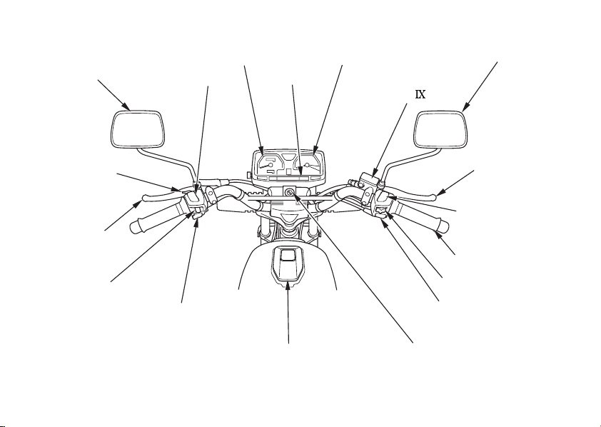
PARTS LOCATION
Rearview mirror
Headlight dimmer
switch
Speedometer
Indicators
Tachometer
Front brake fluid
reservoir
(Type )
Rearview mirror
Passing light
control switch
Clutch lever
Turn signal switch
8
Horn button
Fuel fill cap
Front brake lever
Engine stop switch
Throttle grip
Headlight switch
Start button
Ignition switch
Page 19

Rear spring
preload adjuster
Air cleaner
Spark plug
Passenger footpeg
Oil filler cap/dipstick
Footpeg
Rear brake pedal
Kickstarter
9
Page 20
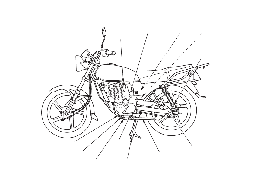
Fuel valve
Choke lever
Battery
Main fuse
Tool kit
Rear spring preload
adjuster
10
Shift lever
Engine oil strainer screen
Engine oil drain plug
Footpeg
Center stand
Side stand
Passenger footpeg
Page 21
INSTRUMENTS AND
INDICATORS
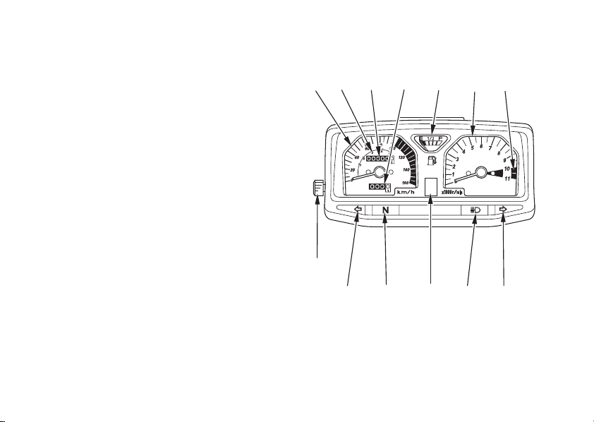
The instruments are grouped together
above the headlight case.
Their functions are described in the table
on the following page.
(1) Speedometer
(2) Gear range
(3) Odometer
(4) Tripmeter
(5) Fuel gauge
(6) Tachometer
(7) Tachometer red zone
(8) Right turn signal indicator
(9) High beam indicator
(10) Gear position indicator
(11) Neutral indicator
(12) Left turn signal indicator
(13) Tripmeter reset knob
(1)
(13)
(2)
(12)
(3) (4)
(11)
(10)
(5)
(9)
(6)
(7)
(8)
11
Page 22

(Ref .No.) Description Function
(1)
Speedometer
Shows riding speed.
(2)
Gear range
(3)
Odometer
(4)
Tripmeter
(5)
Fuel gauge
(6)
Tachometer
(7)
Tachometer red zone
12
Shows proper speed range for each gear.
Shows accumulated mileage.
Shows mileage per trip.
Shows approximate fuel supply available (page ).
Shows engine revolutions per minute.
Never allow the tachometer needle to enter the red
zone, even after the engine has been broken in.
Running the engine beyond recommended maximum
engine speed (the beginning of the tachometer red
zone) can damage the engine.
14
Page 23
(Ref .No.) Description Function
(8)
Right turn signal indicator
Flashes when the right turn signal operates.
(9)
High beam indicator
(10)
Gear position indicator
(11)
Neutral indicator
(12)
Left turn signal indicator
(13)
Tripmeter reset knob
Lights when the headlight is on high beam.
Shows the gear position.
Lights when the transmission is in neutral.
Flashes when the left turn signal operates.
Resets tripmeter to zero (0).
13
Page 24
Fuel Gauge
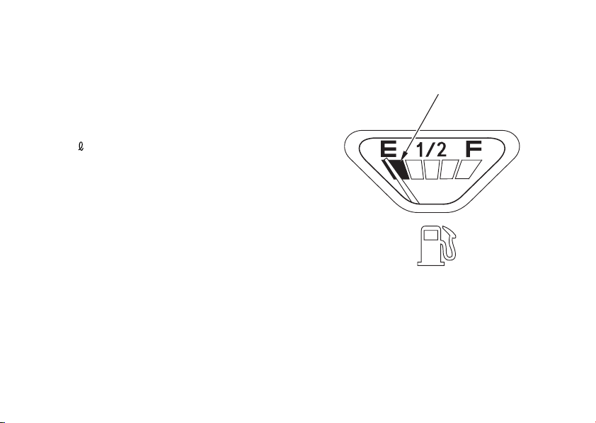
When the gauge needle enters the red band
1
( ), fuel will be low and you should refill
the tank as soon as possible.
The amount of fuel left in the tank when the
needle enters the red band and with the
vehicle set upright is approximately:
(0.55 US gal , 0.46 Imp gal)
2.1
14
(1)
(1) Red band
Page 25
MAJOR COMPONENTS
(Information you need to operate this motorcycle)
SUSPENSION
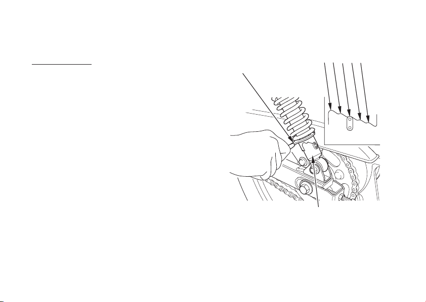
Spring Preload:
Each shock absorber ( ) has 5 adjustment
positions for dif ferent load or riding
conditions.
Use a pin spanner ( ) to adjust the rear
shocks.
Always adjust the shock absorber position
in sequence (1-2-3-4-5 or 5-4-3-2-1).
Attempting to adjust directly from 1 to 5 or
5to1maydamagetheshockabsorber.
Position 1 and 2 are for light loads and
smooth road conditions. Positions 4 and 5
increase spring preload for a stiffer rear
suspension, and can be used when the
motorcycle is heavily loaded. Be certain to
adjust both shock absorbers to the same
position.
Standard position: 3
15
2
(2)
(1) Shock absorber
(2) Pin spanner
12345
(1)
15
Page 26
BRAKES
Front Brake (Type , )
Brakes are items of personal safety and
should always be maintained in proper
adjustment.
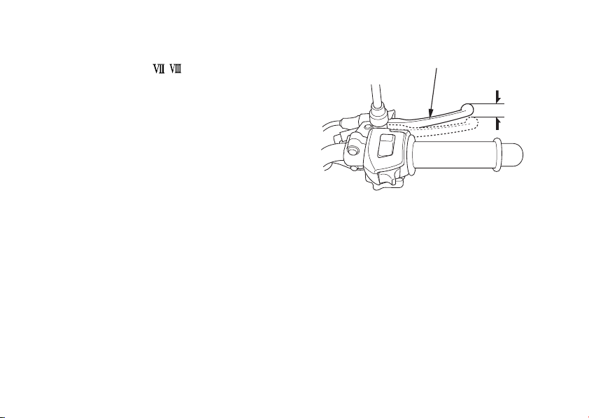
Thedistancethefrontbrakelever( )
1
moves bef ore the brake starts to engage is
called freeplay.
Measured at the tip of the front brake lever
( ), f reeplay should be maintained at:
1
10 20 mm (0.4 0.8 in)
−−
16
(1)
(1) Front brake lever
Page 27

Adjustment:
1.
Major adjustment should be made using
the lower adjusting nut ( ) at the front
2
wheel.
Minor adjustment can be made with the
upper adjusting nut ( ) on the brake
3
lever.
Pull back the rubber dust cover ( ).
Loosen the lock nut ( ).
((AA))
((22))
(2) Lower adjusting nut
(6) Brake arm pin
5
((BB))
(A) Decrease free play
(B) Increase free play
(6)
2.
Adjust brake lever freeplay with the f ront
brake adjusting nut. Turning the nut
clockwise will decrease freeplay and
turning the nut counterclockwise will
increase freeplay.
Make sure the cut-out on the adjusting
nut is seated on the brake arm pin ( )
4
after making final freeplay adjustment.
Tighten the lock nut ( ) and install the
rubber dust cover ( ).
5
4
6
(4)
((BB))
(3)
(3) Upper adjusting nut
(4) Dust cover
(5) Lock nut
((AA))
(A) Decrease free play
(B) Increase free play
(5)
17
Page 28

Apply the brake several times and check for
free wheel rotation after the brake lever is
released.
If proper adjustment cannot be obtained by
this method, see your Honda dealer.
18
Other Checks:
Check the brake cable for kinks or signs of
wear that could cause sticking or failure.
Lubricate the brake cable with a
commercially available cable lubricant to
prevent premature wear and corrosion.
Make sure the brake arm, spring and
fasteners are in good condition.
Page 29
Front Brake (Type )
This motorcycle has a hydraulic f ront disc
brake.
As the brake pads wear, brake fluid level
drops.
There are no adjustments to perf orm, but
fluid level and pad wear must be inspected
periodically. The system must be inspected
frequently to ensure there are no fluid leaks.
If the control lever f ree travel becomes
excessive and the brake pads are not worn
beyond the recommended limit (page ),
92
thereisprobablyairinthebrakesystem
and it must be bled. See your Honda dealer
for this service.
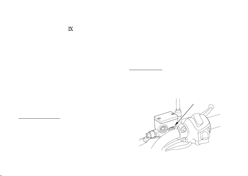
Brake Fluid Level:
With the motorcycle in an upright position,
check the f luid level. It should be above the
LOWER level mark ( ). If the level is at or
below the LOWER level mark ( ), check
the brake pads for wear (page ).
1
1
92
Worn pads should be replaced. If the pads
are not worn, have your brake system
inspected for leaks.
The recommended brake fluid is Honda
DOT 3 or DOT 4 brake fluid from a sealed
container, or an equivalent.
Other Checks:
Make sure there are no fluid leaks. Check
for deterioration or cracks in the hoses and
fittings.
(1)
(1) LOWER level mark
19
Page 30
Rear Brake
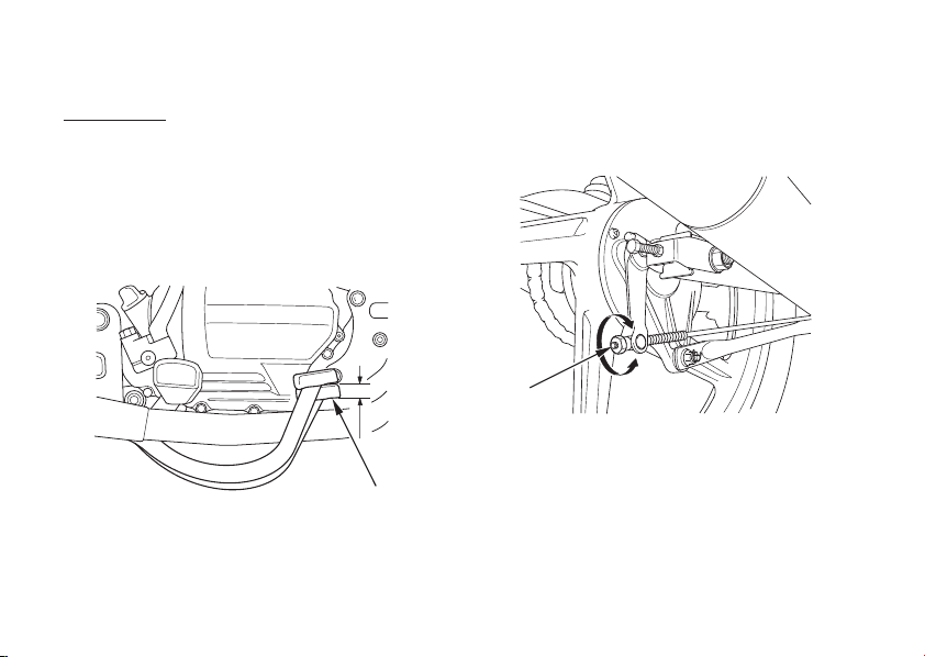
Place the motorcycle on its center stand.
1.
Measure the distance the rear brake
2.
pedal ( ) moves before the brake starts
1
to take hold.
Freeplay should be:
20 30 mm (0.8 1.2 in)
−−
If adjustment is necessary, turn the rear
3.
brake adjusting nut ( ).Adjustment:
2
((AA))
(1) Rear brake pedal
20
(1)
(2)
(2) Adjusting nut
(A) Decrease free play
(B) Increase free play
((BB))
Page 31

Apply the brake several times and check
4.
for free wheel rotation after the brake
pedal is released.
Make sure the cut-out on the adjusting nut
is seated on the brake arm pin ( ) after
3
making final freeplay adjustment.
If proper adjustment cannot be obtained by
this method, see your Honda dealer.
(3)
(3) Brake arm pin
Other Checks:
Make sure the brake rod, brake arm, spring
and fasteners are in good condition.
21
Page 32
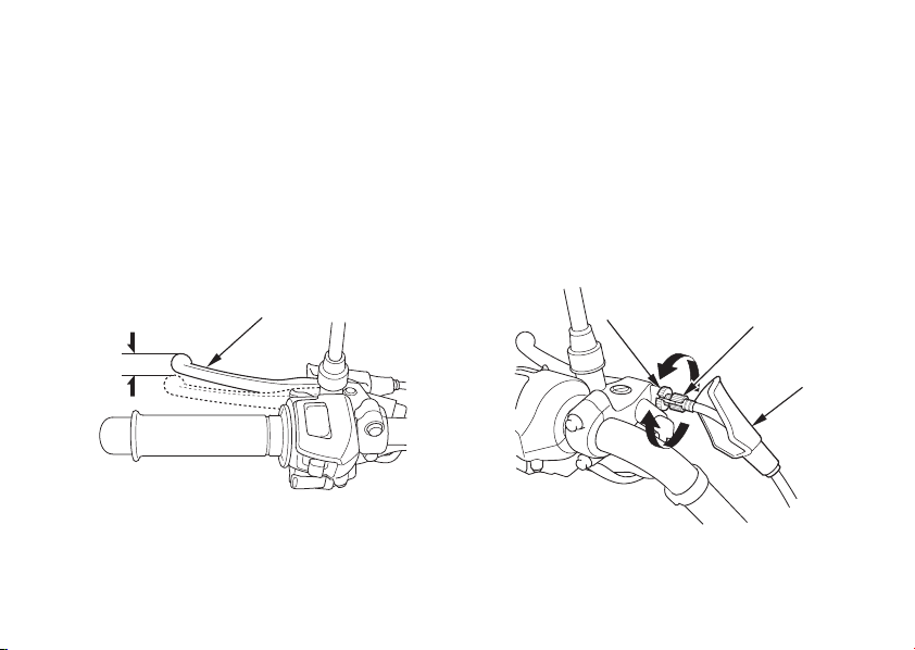
CLUTCH
Clutch adjustment may be required if the
motorcycle stalls when shifting into gear or
tends to creep; or if the clutch slips, causing
acceleration to lag behind engine speed.
Minor adjustments can be made with the
clutch cable adjuster ( ) at the clutch lever
().
1
4
Normal clutch lever freeplay is:
10 20 mm (0.4 0.8 in)
−−
1.
Pull back the rubber dust cover ( ).
2.
Loosen the lock nut ( ) and turn the
3
2
clutch cable adjuster. Tighten the lock
nut and check the adjustment.
3.
If the adjuster is threaded out near its
limit or if the correct freeplay cannot be
obtained, loosen the lock nut and turn in
the clutch cable adjuster completely.
Tighten the lock nut and install the dust
cover.
22
(1)
(3)
((AA))
(2) Dust cover
(3) Lock nut
(4) Clutch cable adjuster
((BB))
(4)
(2)
(A) Increase free play
(B) Decrease free play(1) Clutch lever
Page 33

Loosen the lock nut ( ) at the lower end
4.
5
of the cable. Turn the adjusting nut ( ) to
obtain the specified freeplay. Tighten the
lock nut and check the adjustment.
Start the engine, pull in the clutch lever
5.
and shif t into gear. Make sure the engine
does not stall and the motorcycle does
not creep. Gradually release the clutch
lever and open the throttle. The
motorcycle should begin to move
smoothly and accelerate gradually.
(6)
((AA))
((BB))
6
(5)
If proper adjustment cannot be obtained or
the clutch does not work correctly, see your
Honda dealer.
Other Checks:
Check the clutch cable for kinks or signs of
wear that could cause sticking or failure.
Lubricate the clutch cable with a
commercially available cable lubricant to
prevent premature wear and corrosion.
(5) Lock nut
(6) Adjusting nut
(A) Increase free play
(B) Decrease free play
23
Page 34
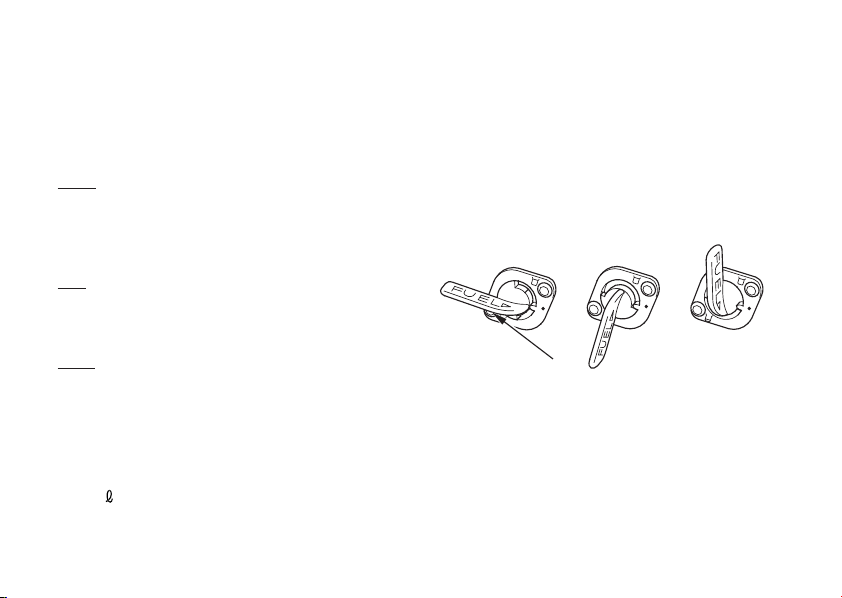
FUEL
Fuel Valve
Thethreewayfuelvalve( )isontheleft
1
side near the carburetor.
OFF
With the fuel valve in the OFF position, fuel
cannot flow from the tank to the carburetor.
Turn the valve OFF whenever the
motorcycle is not in use.
ON
With the fuel valve in the ON position, fuel
will flow from the main fuel supply to the
carburetor.
RES
With the fuel valve in the RES position, fuel
will flow f rom the reserve fuel supply to the
carburetor. Use the reserve fuel only when
themainsupplyisgone.Refillthetankas
soon as possible after switching to RES.
The reserve fuel supply is:
2.7
(0.71 US gal , 0.59 Imp gal)
24
Remember to check that the fuel valve is in
the ON position each time you refuel. If the
valve is left in the RES position, you may
run out of fuel with no reserve.
OFF RESON
(1)
(1) Fuel valve
Page 35

Fuel Tank
The fuel tank capacity including the reserve
supply is:
To open the f uel fill cap ( ), insert the
ignition key ( ) and turn it clockwise. The
2
1
(2.77 US gal , 2.31 Imp gal)
10.5
fuel f ill cap is hinged and will lift up.
Do not overfill the tank. There should be no
fuel in the filler neck ( ).
3
After refueling, to close the fuel fill cap,
push the fuel fill cap into the filler neck until
it snaps closed and locks. Remove the key.
Petrol is highly flammable and
explosive. You can be burned or
seriously injured when handling fuel.
(3)
(1)
(2)
Stop the engine and keep heat,
sparks, and flame away.
Refuel only outdoors.
Wipe up spills immediately.
(1) Fuel fill cap
(2) Ignition key
(3) Filler neck
25
Page 36
Use unleaded or low-lead petrol with a
research octane number of 91 or higher.
We recommend that you use unleaded
petrol because it produces fewer engine and
spark plug deposits and extends the life of
exhaust system components.
26
If ‘‘spark knock’’ or ‘‘pinking’’ occurs at a
steady engine speed under normal load,
change brands of petrol. If spark knock or
pinking persists, consult your Honda dealer.
Failure to do so is considered misuse, and
damage caused by misuse is not covered by
Honda’s Limited Warranty.
Page 37

Petrol Containing Alcohol
If you decide to use a petrol containing
alcohol(gasohol),besureit’soctanerating
is at least as high as that recommended by
Honda. There are two types of ‘‘gasohol’’:
one containing ethanol, and the other
containing methanol. Do not use petrol that
contains more than 10 % ethanol. Do not use
petrol containing methanol (methyl or wood
alcohol) that does not also contain
cosolvents and corrosion inhibitors for
methanol. Never use petrol containing more
than 5 % methanol, even if it has cosolvents
and corrosion inhibitors.
Fuel system damage or engine performance
problems resulting from the use of fuels
that contain alcohol is not covered under
the warranty. Honda cannot endorse the
use of f uels containing methanol since
evidence of their suitability is as yet
incomplete.
Before buying fuel f rom an unfamiliar
station, try to find out if the f uel contains
alcohol. If it does, confirm the type and
percentage of alcohol used. If you notice
any undesirable operating symptoms while
using a petrol that contains alcohol, or one
that you think contains alcohol, switch to a
petrol that you know does not contain
alcohol.
27
Page 38

ENGINE OIL
Engine Oil Level Check
Check the engine oil level each day before
riding the motorcycle.
The level must be maintained between the
upper( )andlower( )levelmarksonthe
12
oil filler cap/dipstick ( ).
Start the engine and let it idle for 3 5
1.
3
−
minutes.
Stop the engine and put the motorcycle
2.
on its center stand on level ground.
3.
−
After 2 3 minutes, remove the oil f iller
cap/dipstick ( ), wipe it clean, and
3
reinsert the oil filler cap/dipstick without
screwing it in. Remove the oil filler cap/
dipstick. The oil level should be between
the upper ( ) and lower ( ) level marks
1
2
on the oil filler cap/dipstick.
4.
If required, add the specified oil (see
page ) up to the upper level mark. Do
64
not overfill.
28
5.
Reinstall the oil filler cap/dipstick. Check
for oil leaks.
Running the engine with insufficient oil
pressure may cause serious engine damage.
(3)
(1)
(2)
(1) Upper level mark
(2) Lower level mark
(3) Oil filler cap/dipstick
Page 39

To safely operate your motorcycle, the tyres
must be the proper type and size, in good
condition with adequate tread, and correctly
inflated.
Using tyres that are excessively worn
or improperly inflated can cause a
crash in which you can be seriously
hurt or killed.
Follow all instructions in this owner’s
manual regarding tyre inflation and
maintenance.
Air PressureTYRES
Properly inflated tyres provide the best
combination of handling, tread life, and
riding comfort. Generally, underinflated
tyres wear unevenly, adversely affect
handling, and are more likely to fail from
being overheated. Underinflated tyres can
also cause wheel damage in rocky terrain.
Overinflated tyres make your motorcycle
ride harshly, are more prone to damage
from surface hazards, and wear unevenly.
Make sure the valve stem caps are secure.
If necessary, install a new cap.
29
Page 40
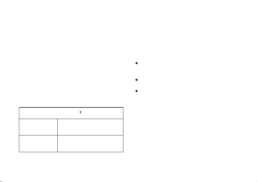
Always check air pressure when your tyres
are ‘‘cold’’ when the motorcycle has been
−
parked for at least three hours. If you check
air pressure when your tyres are ‘‘warm’’
−
when the motorcycle has been ridden for
even a few miles the readings will be
−
higher than if the tyres were ‘‘cold’’. This is
normal, so do not let air out of the tyres to
match the recommended cold air pressures
given below. If you do, the tyres will be
underinflated.
The recommended ‘‘cold’’ tyre pressures
are:
kPa (kgf/cm , psi)
Driver
only
Front
Rear
200 (2.00 , 29)
225 (2.25 , 33)
Inspection
Whenever you check the tyre pressures,
youshouldalsoexaminethetyretreadsand
sidewalls for wear, damage, and foreign
objects:
Look for:
Bumps or bulges in the side of the tyre or
thetread.Replacethetyreifyoufindany
bumps or bulges.
Cuts, splits or cracks in the tyre. Replace
the tyre if you can see fabric or cord.
Excessive tread wear.
Also, if you hit a pothole or hard object, pull
to the side of the road as soon as you safely
can and carefully inspect the tyres for
damage.
Driver and
one passenger
30
Front
Rear
200 (2.00 , 29)
225 (2.25 , 33)
Page 41
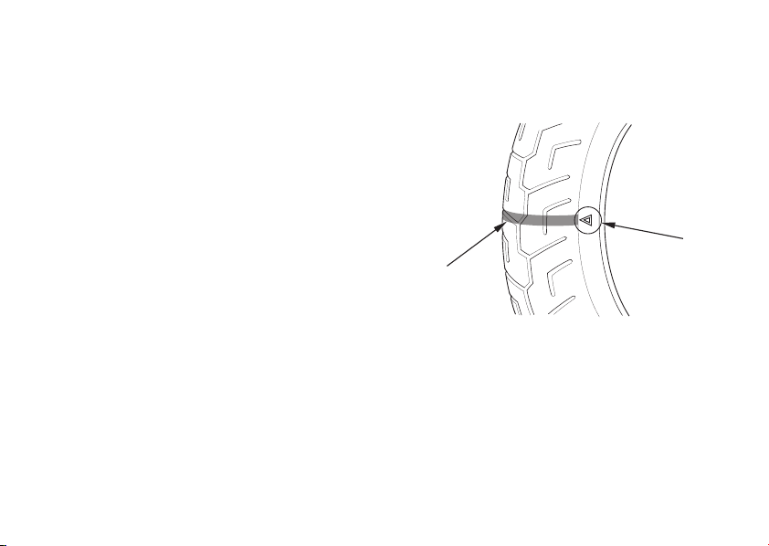
Tread Wear
Replace tyres immediately when the wear
indicator appears at on the tyre.
(2)
(1)
(1) Wear indicator
(2) Wearindicatorlocationmark
31
Page 42

Tube Repair and Replacement
If a tube is punctured or damaged, you
should replace it as soon as possible. A tube
that is repaired may not have the same
reliability as a new one, and it may fail while
you are riding.
If you need to make a temporary repair by
patching a tube or using an aerosol sealant,
ride cautiously at reduced speed and have
the tube replaced before you ride again.
Anytimeatubeisreplaced,thetyreshould
be carefully inspected as described on page
.
30
32
Page 43
Tyre Replacement
The tyres that came on your motorcycle
were designed to match the performance
capabilities of your motorcycle and provide
the best combination of handling, braking,
durability and comf ort.
The recommended tyres for your
motorcycle are:
Front:
2.75 18 42P
−
2.75 18 48P
−
90/90 18M/C 51P
Rear:
Type:
−
bias-ply, tube
Installing improper tyres on your
motorcycle can affect handling and
stability. This can cause a crash in
which you can be seriously hurt or
killed.
Always use the size and type of tyres
recommended in this owner’s manual.
Whenever you replace a tyre, use one that
is equivalent to the original and be sure the
wheel is balanced after the new tyre is
installed.
Also remember to replace the inner tube
whenever you replace a tyre. The old tube
will probably be stretched, and if installed in
a new tyre, it could fail.
33
Page 44
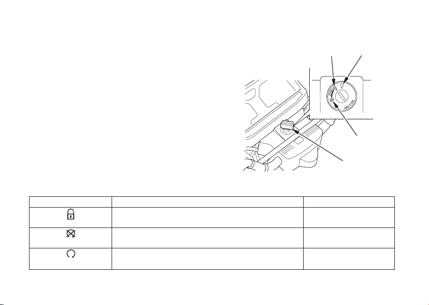
ESSENTIAL INDIVIDUAL COMPONENTS
IGNITION SWITCH
The ignition switch ( ) is below the
indicator panel.
1
(1) Ignition switch
ONOFF
LOCK
(1)
Key Position
(steering lock)
OFF
ON
34
Steering is locked. Engine and lights cannot
be operated.
Engine and lights cannot be operated.
Engine and lights can be operated.
Key RemovalFunction
Key can be
removed
Key can be
removed
Key cannot be
removed
Page 45
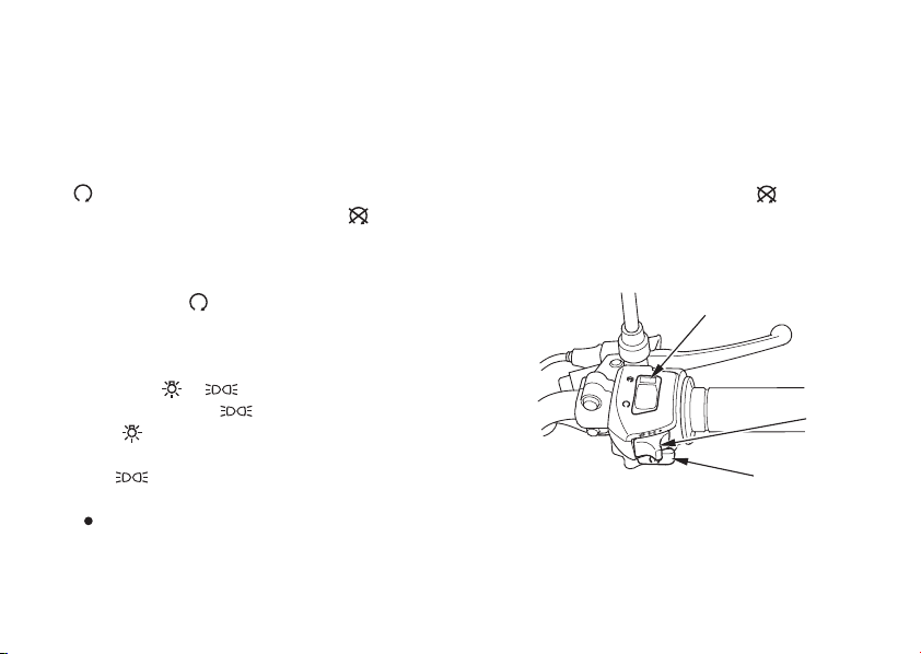
RIGHT HANDLEBAR CONTROLS
Engine Stop Switch
The engine stop switch ( ) is next to the
1
throttle grip. When the switch is in the
(RUN) position, the engine will operate.
When the switch is in the (OFF)
position, the engine will not operate. This
switch is intended primarily as a safety or
emergency switch and should normally
remain in the (RUN) position.
Start Button
The start button ( ) is next to the throttle
3
grip.
When the start button is pressed, the
starter motor cranks the engine. If the
engine stop switch is in the (OFF)
position, the engine will not operate. See
page for the starting procedure.
45
(1)
Headlight Switch
The headlight switch ( ) has three
2
positions; , and OFF marked by a
dot to the right of .
:
Headlight, taillight and meter
lights on.
:
Position light, taillight and
meter lights on.
(OFF):
Headlight, taillight, position
light and meter lights off.
(2)
(3)
(1) Engine stop switch
(2) Headlight switch
(3) Start button
35
Page 46

LEFT HANDLEBAR CONTROLS
Headlight Dimmer Switch ( )
1
Push the dimmer switch to (HI) to
select high beam or to (LO) to select
low beam.
Passing Light Control Switch ( )
2
When this switch is pressed, the headlight
flashes on to signal approaching cars or
when passing.
Turn Signal Switch ( )
3
Move to (L) to signal a left turn,
(R) to signal a right turn. Press to turn
signal off.
Horn Button ( )
4
Press the button to sound the horn.
36
(1)(2)
(4)
(3)
(1) Headlight dimmer switch
(2) Passing light control switch
(3) Turn signal switch
(4) Horn button
Page 47

FEATURES
(Not required f or operation)
STEERING LOCK
The steering can be locked when the
ignition switch ( ) is in the ‘‘ (LOCK)’’
position.
To lock the steering, turn the handlebars all
the way to the left or right, turn the key ( )
to (LOCK) while pushing in. Remove the
key.
To unlock the steering, turn the key to
(OFF).
1
(2)
((BB))2
To lock
(A)
Do not turn the key to (LOCK) while
riding the motorcycle; loss of vehicle
control will result.
(1)
(1) Ignition switch
(2) Ignition key
((CC))
To unlock
(A) Push in
(B) Turn to (LOCK)
(C) Turn to (OFF)
37
Page 48

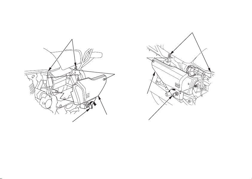
SIDE COVERS
The right side cover must be removed for
the air cleaner maintenance. The left side
cover must be removed for battery and fuse
maintenance, to access the tool kit.
The right and left side covers can be
removed in the same manner.
38
Removal:
Insert the ignition key ( ) into the lock
1.
andturnitclockwise.
2. 2
Carefully pull the side cover ( ) out from
the grommets ( ).
Installation:
Installation can be done in the reverse
order of removal.
3
1
Page 49
Left side
(3)
Right side
(2)
(3)
(1) Ignition key
(2) Side cover
(1)
(3) Grommets
(2)
(1)
39
Page 50
SEAT
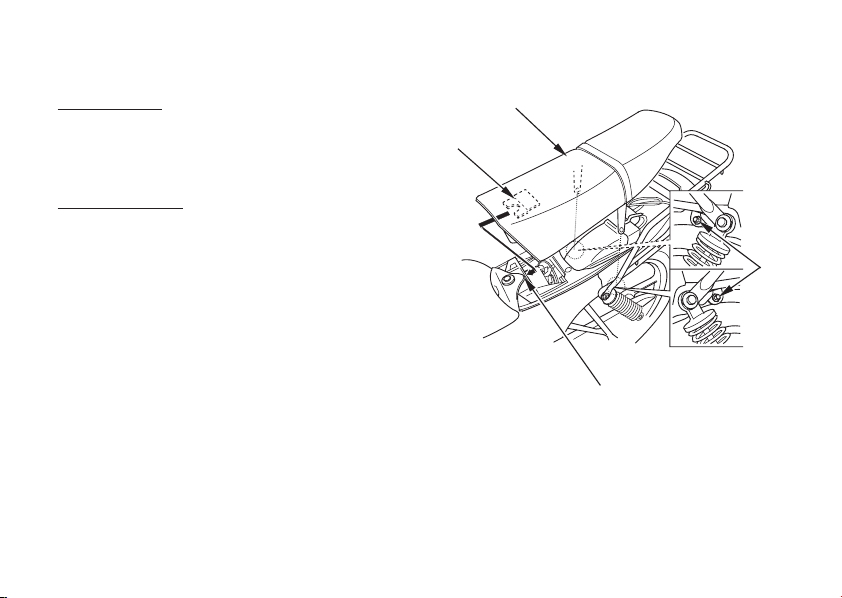
Seat removal:
Remove the seat mounting bolts ( ) on
1.
both sides.
Pull the seat ( ) back and up.
2.
2
(2)
1
(3)
Seat installation:
Insert the prong ( ) into the recess ( )
1.
3
under the f rame.
Tighten the seat mounting bolts securely.
2.
40
4
(1)
(4)
(1) Bolts
(2) Seat
(3) Prong
(4) Recess
Page 51
HEADLIGHT AIM VERTICAL
ADJUSTMENT
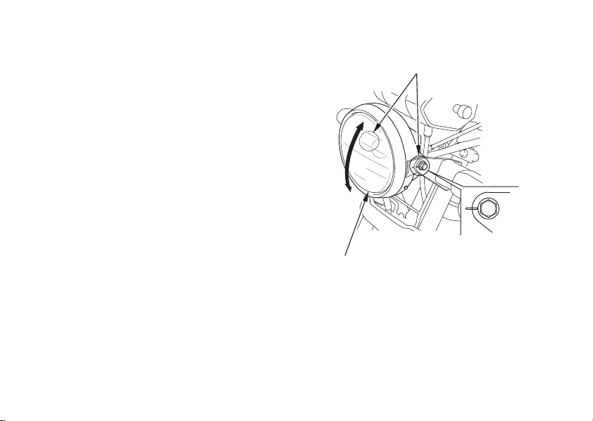
Vertical adjustment can be made by moving
the headlight case ( ) as necessary.
To move the headlight case ( ), loosen the
bolts ( ).
2
Tighten the bolts ( ) af ter adjustment.
1
1
2
Obey local laws and regulations.
(2)
((AA))
((BB))
(1)
(1) Headlight case
(2) Bolts
(A) Up
(B) Down
41
Page 52
OPERATION
PRE-RIDE INSPECTION
For your safety, it is very important to take
a few moments before each ride to walk
around your motorcycle and check its
condition. If you detect any problem, be
sure you take care of it, or have it corrected
by your Honda dealer.
Improperly maintaining this motorcycle
or failing to correct a problem before
riding can cause a crash in which you
can be seriously hurt or killed.
Always perform a pre-ride inspection
before every ride and correct any
problems.
42
1.
Engine oil level add engine oil if
required (page ). Check for leaks.
2.
Fuel level fill fuel tank when necessary
(page ). Check for leaks.
3.
Brakes check operation;
(Type , )
Front and rear: adjust free play if
necessary (pages , ).
(Type )
Front: Make sure there is no brake fluid
leakage (page ).
Rear: adjust freeplay if necessary (pages
20 21
4.
Tyres check condition and pressure
(pages ).
5.
Drivechain checkconditionandslack
(page ). Adjust and lubricate if
necessary.
25
−
−
−
29 32
76
−
).
−
−
−
28
−−
19
20
2116 18
Page 53

6.
Throttle check for smooth opening and
full closing in all steering positions.
7.
Lights and horn check that headlight,
brake/tail light, turn signals, indicators
and horn function properly.
8.
Engine stop switch check f or proper
function (page ).
9.
Battery electrolyte check the level and
add if necessary (page ).
−
−
−
35
−
95
43
Page 54

STARTING THE ENGINE
Always f ollow the proper starting procedure
described below.
This motorcycle can be kickstarted with the
transmission in gear by disengaging the
clutch before operating the kickstarter.
Your motorcycle’s exhaust contains
poisonous carbon monoxide gas. High
levels of carbon monoxide can collect
rapidly in enclosed areas such as a garage.
Do not run the engine with the garage door
closed. Even with the door open, run the
engine only long enough to move your
motorcycle out of the garage.
Do not use the electric starter for more than
5 seconds at a time. Release the start button
for approximately 10 seconds before
pressing it again.
44
Page 55

Before starting, insert the key, turn the
ignition switch (ON) and conf irm the
following:
The transmission is in NEUTRAL
(neutral indicator light ON). With the throttle slightly open, press the
The engine stop switch is at (RUN).
The fuel valve is ON.
Do not operate the kickstarter while the
engine is running as engine damage could
result. Do not apply excessive force on the
kickstarter.
Fold up the kickstarter after the kickstarter
is returned to the pedal stop.
Starting ProcedurePreparation
Cold Engine:
1.
Pull the choke lever ( ) up all the way to
Fully ON ( ).
(Use the start button)
2.
start button.
Do not use the electric starter for more than
5 seconds at a time. Release the start button
for approximately 10 seconds before
pressing it again.
(Use the kickstarter)
Lightly depress the kickstarter until
resistance is felt.
Then let the kickstarter return to the top
of its stroke.
With the throttle slightly open, operate
the kickstarter. Kick from the top of the
stroke through to the bottom with a rapid,
continuous motion.
A
1
45
Page 56
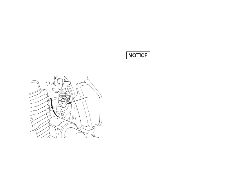
Immediately after the engine starts, push
3.
the choke lever ( ) down to the Halfway
Position ( ).
Warm up the engine by opening and
4.
B
1
closing the throttle slightly.
Continue warming up the engine until it
5.
runs smoothly and responds to the
throttle, when the choke lever ( ) is at
Fully OFF ( ).
C
1
Warm Engine:
1.
Do not use the choke.
2.
Start the engine following step 2 under
‘‘Cold Engine.’’
Extended use of the choke may impair
piston and cylinder wall lubrication and
damage the engine.
((AA))
((BB))
((CC))
(1) Choke lever (A) Fully ON
(B) Halfway position
(C) Fully OFF
46
(1)
Page 57

Flooded Engine
Using the kickstarter
〈〉
If the engine f ails to start af ter several
repeated attempts, it may have become
flooded with excess fuel. To clear the
engine, turn off the ignition switch and
move the choke lever to Fully OFF ( ).
Open the throttle fully and crank the engine
several times with the kickstarter. Turn the
ignition switch to (ON) and open the
throttle slightly; start the engine using the
kickstarter.
C
Using the electric starter
〈〉
If the engine fails to start after repeated
attempts, it may be flooded with excess fuel.
To clear a flooded engine, turn the ignition
switch to (ON) and move the choke lever
to Fully OFF ( ). Open the throttle fully
and press the start button for 5 seconds. If
the engine starts, quickly close the throttle,
then open it slightly if idling is unstable. If
the engine does not start, wait 10 seconds,
then follow the Starting Procedure.
C
47
Page 58

RUNNING-IN
Help assure your motorcycle’s f uture
reliability and perf ormance by paying extra
attention to how you ride during the first
500 km (300 miles).
During this period, avoid f ull-throttle starts
and rapid acceleration.
48
Page 59
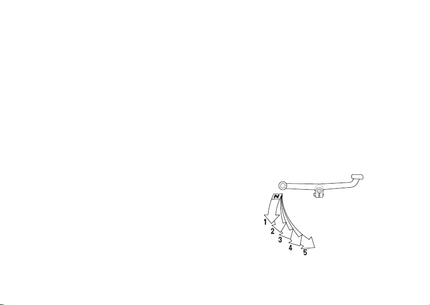
RIDING
17
−Review Motorcycle Safety (pages )
before you ride.
Make sure you understand the function of
the side stand mechanism. (See MAINTENANCE SCHEDULE on page and
explanation for SIDE STAND on page ).
1.
Warm up the engine.
2.
With the engine idling, shif t into low (1st)
58
84
by pull in the clutch lever and depressing
the toe end of the shift lever.
3.
Slowly release the clutch lever and at the
same time gradually increase engine
speed by opening the throttle. Close the
throttle, pull in the clutch lever and
depress the toe end of the shift lever to
shift into 2nd gear.
4.
This sequence is repeated to
progressively shift into the next higher
gear.
5.
Shifting down is accomplished by
depressing the heel end of the shift lever.
6.
Coordinate the throttle and brakes for
smooth deceleration.
Both front and rear brakes should be
7.
usedatthesametimeandshouldnotbe
applied strongly enough to lock the wheel,
or braking effectiveness will be reduced
and control of the motorcycle be diff icult.
TOE END HEEL END
49
Page 60

SHIFTING
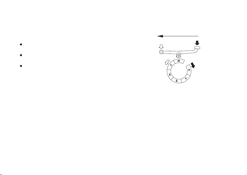
The gearshift operation differs when
stopping and when moving.
When stopping, change can be made
from 5th to neutral directly with the 5-step
rotary system.
Forward
Stopping
50
(N) Neutral
(1) First
(2) Second
(3) Third
(4) 4th
(5) 5th (Top)
Page 61
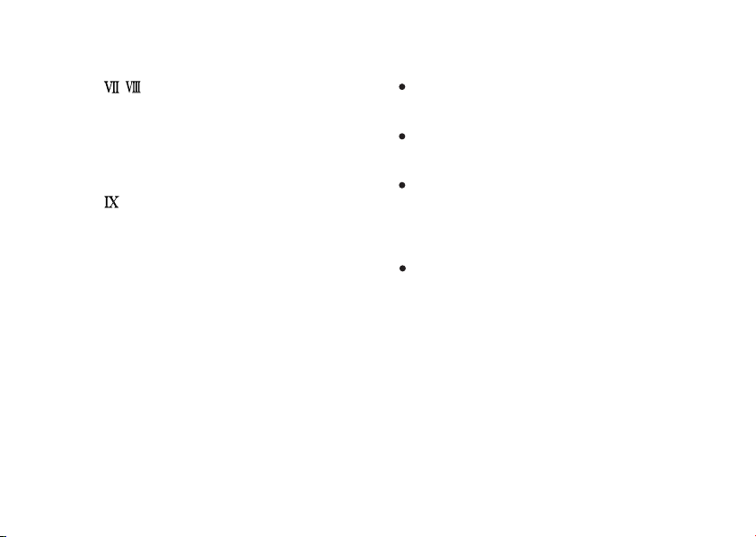
When moving, the forward 5-step return
system is used.
Change cannot be made from 5th to neutral
directly.
Always return the throttle grip first
before changing gear.
Operate lightly with the tips of your toes
until the shif t lever is pushed down.
Avoid changing gear needlessly and
riding with your foot on the shift lever
since this may damage the gear change
mechanism and clutch mechanism.
Forward
Moving
(N) Neutral
(1) First
(2) Second
(3) Third
(4) 4th
(5) 5th (Top)
51
Page 62
BRAKING
(Type , )
Your motorcycle is equipped with
mechanically-activated drum brakes.
Operating the brake lever applies the front
drum brake. Depressing the brake pedal
applies the rear drum brake.
(Type )
Your motorcycle is equipped with a
hydraulically-activated disc brake in front
and a mechanically-activated drum brake at
the rear. Operating the brake lever applies
the front disc brake. Depressing the brake
pedal applies the rear drum brake.
For normal braking, apply both the brake
pedal and lever while down-shifting to
match your road speed. For maximum
braking, close the throttle and firmly apply
the pedal and lever; pull in the clutch lever
before coming to a complete stop to prevent
stalling the engine.
52
Important Safety Reminders:
Independent operation of only the brake
lever or brake pedal reduces stopping
performance.
Extreme application of the brake controls
may cause wheel lock, reducing control of
the motorcycle.
When possible, reduce speed or brake
before entering a turn; closing the
throttle or braking in mid-turn may cause
wheel slip. Wheel slip will reduce control
of the motorcycle.
When riding in wet or rainy conditions, or
on loose surfaces, the ability to maneuver
and stop will be reduced. All of your
actions should be smooth under these
conditions. Rapid acceleration, braking or
turning may cause loss of control. For
your safety, exercise extreme caution
when braking, accelerating or turning.
Page 63

When descending a long, steep grade,
useenginecompressionbrakingbydownshifting, with intermittent use of both
brakes.
Continuous brake application can
overheat the brakes and reduce their
effectiveness.
Riding with your foot resting on the
brake pedal or your hand on the brake
lever may actuate the brakelight, giving a
false indication to other drivers. It may
also overheat the brakes, reducing
effectiveness.
PARKING
1.
After stopping the motorcycle, shift the
transmission into neutral, turn the fuel
valve OFF, turn the handlebar fully to the
left, turn the ignition switch (OFF) and
remove the key.
Use the side or center stand to support
2.
the motorcycle while parked.
Park the motorcycle on firm, level ground to
prevent it f rom f alling over.
Ifyoumustparkonaslightincline,aimthe
front of the motorcycle uphill to reduce the
possibility of overturning or rolling off the
center or side stand.
3.
Lock the steering to help prevent theft
37
(page ).
53
Page 64

ANTI-THEFT TIPS
1.
Always lock the steering and never leave
the key in the ignition switch. This
sounds simple but people do forget.
2.
Be sure the registration information for
your motorcycle is accurate and current.
3.
Park your motorcycle in a locked garage
whenever possible.
4.
Use an additional anti-theft device of
good quality.
5.
Put your name, address, and phone
number in this Owner’s Manual and keep
it on your motorcycles at all times.
Many times stolen motorcycles are
identified by information in the Owner’s
Manuals that are still with them.
NAME:
ADDRESS:
PHONE NO:
54
Page 65
MAINTENANCE
THE IMPORTANCE OF
MAINTENANCE
A well-maintained motorcycle is essential
for safe, economical and trouble-free riding.
It will also help reduce air pollution.
To help you properly care for your
motorcycle, the following pages include a
Maintenance Schedule and a Maintenance
Record f or regularly scheduled
maintenance.
These instructions are based on the
assumption that the motorcycle will be used
exclusively for its designed purpose.
Sustained high speed operation or operation
in unusually wet or dusty conditions will
require more frequent service than
specified in the Maintenance Schedule.
Consult your Honda dealer for
recommendations applicable to your
individual needs and use.
If your motorcycle overturns or becomes
involved in a crash, be sure your Honda
dealer inspects all major parts, even if you
areabletomakesomerepairs.
Improperly maintaining this motorcycle
or failing to correct a problem before
youridecancauseacrashinwhich
you can be seriously hurt or killed.
Always follow the inspection and
maintenance recommendations and
schedules in this owner’s manual.
55
Page 66

MAINTENANCE SAFETY
This section includes instructions on some
important maintenance tasks. You can
perform some of these tasks with the tools
provided if you have basic mechanical
skills.
−
Failure to properly follow maintenance
instructions and precautions can
cause you to be seriously hurt or killed.
Other tasks that are more difficult and
require special tools are best performed by
professionals. Wheel removal should
normally be handled only by a Honda
technician or other qualified mechanic;
instructions are included in this manual only
to assist in emergency service.
Some of the most important safety
precautions follow. However, we cannot
warn you of every conceivable hazard that
can arise in performing maintenance. Only
you can decide whether or not you should
perform a given task.
56
Always follow the procedures and
precautions in this owner’s manual.
Page 67

SAFETY PRECAUTIONS
Make sure the engine is off before you
begin any maintenance or repairs. This
will help eliminate several potential
hazards:
Carbon monoxide poisoning from
engine exhaust.
Be sure there is adequate ventilation
whenever you operate the engine.
Burns from hot parts.
Let the engine and exhaust system cool
before touching.
Injury from moving parts.
Do not run the engine unless instructed
to do so.
Read the instructions bef ore you begin,
and make sure you have the tools and
skills required.
To help prevent the motorcycle from
falling over, park it on a f irm, level
surface, using the center stand or a
maintenance stand to provide support.
To reduce the possibility of a fire or
explosion, be careful when working
around petrol or batteries. Use only
nonflammable solvent, not petrol, to clean
parts. Keep cigarettes, sparks and flames
away from the battery and all fuel-related
parts.
Remember that your Honda dealer knows
your motorcycle best and is fully equipped
to maintain and repair it.
To ensure the best quality and reliability,
use only new genuine Honda parts or their
equivalents for repair and replacement.
57
Page 68

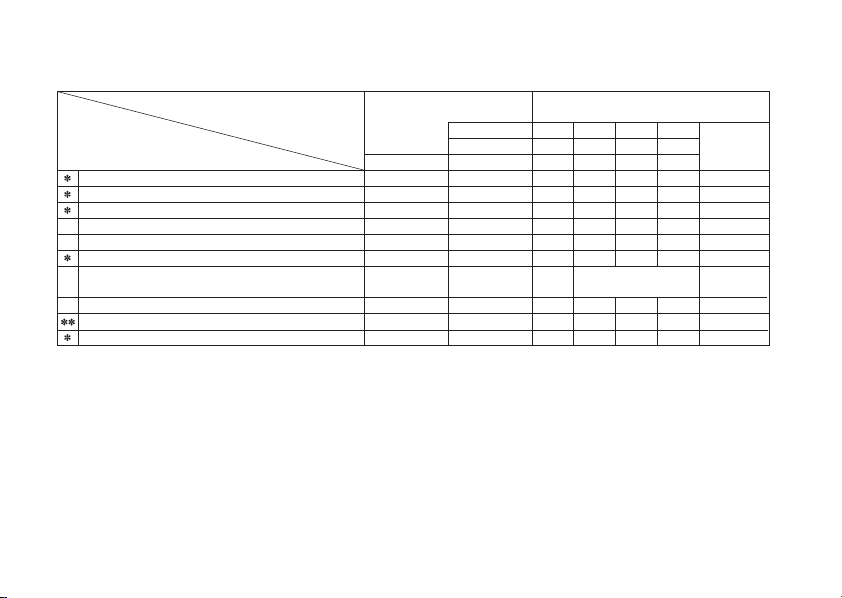
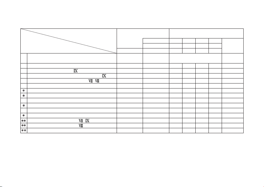
MAINTENANCE SCHEDULE
Perform the Pre-ride Inspection (page ) at each scheduled maintenance period.
I: INSPECT AND CLEAN, ADJUST, LUBRICATE OR REPLACE IF NECESSARY
C: CLEAN R: REPLACE A: ADJUST L: LUBRICA TE
The f ollowing items require some mechanical knowledge. Certain items (particularly those marked and ) may
require more technical information and tools. Consult your Honda dealer.
Should be serviced by your Honda dealer, unless the owner has proper tools and service dat a and is mechanically
qualified. Refer to the Of ficial Honda Shop Manual.
In the interest of safety, we recommend these items be serviced only by your Honda dealer.
Honda recommends that your Honda dealer should road test your motorcycle af ter each periodic maintenance is
carried out.
NOTES:42(1)
At higher odometer readings, repeat at the frequency interval established here.
Service more f requently if the motorcycle is ridden in unusually wet or dusty areas.
(2)
Service more f requently when riding OFF-ROAD.
(3)
Replace every 2 years. Replacement requires mechanical skill.
(4)
***
58
Page 69
FREQUENCY WHICHEVER
ITEMS
FUEL LINE
FUEL STRAINER SCREEN
THROTTLE OPERATION
AIR CLEANER
SPARK PLUG
VALVE CLEARANCE
ENGINE OIL
ENGINE OIL STR AINER SCREEN
ENGINE OIL CENT RIFUGAL FILTER
ENGINE IDLE SPEED
COMES
FIRST
↓
NOTE
NOTE
(2)
→
×
1,000 km
×
1,000 mi
MONTHS
ODOMETER R EADING [NOTE (1)]
Refer
12
8
4
0.6
1
2.5
I
R
I
5
12
6
I
I
C
C
I
I
C
C
R
I
I
I
EVERY 3,000 km
(2,000 mi) R
I
I
7.5
to
pages
18
−
I
−
C
72
I
74
C
68
I
70
I
64
67
C
−
C
73
I
59
Page 70
ITEM
DRIVE CHAIN
BATTERY
BRAK E FLUID
BRAKE SHOES/PADS WEAR
BRAKE SHOES WEAR
BRAK E SYST EM
BRAK ELIGHT SWIT CH
HEADLIGHT AIM
CLUTCH SYSTEM
SUSPENSION
SIDE STAND
NUTS, BOLTS,FASTENERS
WHEELS/TYRES
WHEELS/TYRES
STEERING HEAD BEARINGS
60
(Type )
(Type / )
(Type / )
(Type )
FREQUENCY
(Type )
WHICHEVER
COMES
FIRST
↓
NOTE
(3)
NOTE
(4)
NOTE
(3)
NOTE
(3)
NOTE
→
×
1,000 km
×
1,000 mi
MONTHS
ODOMETER R EADING [NOTE (1)]
4
1
0.6
EVERY 1,000 km
(600 mi) I, L
I
I
I
I
I
2.5
8
12
7.5
18
I
I
I
I
I
I
I
I
I
I
I
I
I
Refer
to
page
76
93
19
91, 92
91
16, 91, 92
100
41
22
83
84
−
−
−
−
5
6
12
I
I
I
I
I
I
I
I
I
I
I
I
I
I
I
I
I
I
I
I
I
I
I
I
I
Page 71

TOOL KIT
The tool kit ( ) is in the tool box ( ) under
1
2
the battery behind the left side cover (page
38
).
Some roadside repairs, minor adjustments
and parts replacement can be performed
with the tools contained in the kit.
812mmOpenendwrench
×
10 14 mm Open end wrench
×
22 mm Box end wrench
18 mm Box end wrench
Sparkplugwrench
No. 2 Phillips screwdriver
No. 2 screwdriver
Pliers
Extension bar
Pin spanner
Tool bag
(2)
(1)
(1) Tool kit
(2) Tool box
61
Page 72
SERIAL NUMBERS
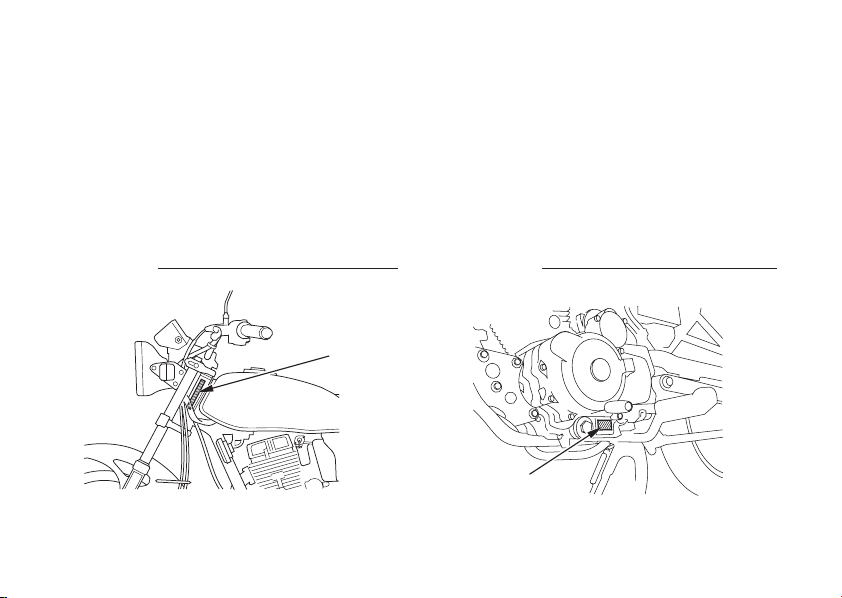
The f rame and engine serial numbers are
required when registering your motorcycle.
The frame number ( ) is stamped on the
left side of the steering head.
Theymayalsoberequiredbyyourdealer
when ordering replacement parts.
Record the numbers here for your
The engine number ( ) is stamped on the
lower left side of the crankcase.
reference.
FRAME NO. ENGINE NO.
(1)
(2)
(1) Frame number (2) Engine number
62
1
2
Page 73

COLOUR LABEL
The colour label ( ) is attached to the right
1
side of the frame.
It is helpful when ordering replacement
parts. Record the colour and code here for
your reference.
COLOUR
CODE
(1)
(1) Colour label
63
Page 74
ENGINE OIL
Refer to the Safety Precautions on page .
57
Engine Oil
Good engine oil has many desirable
qualities. Use only high detergent, quality
motor oil certified on the container to meet
or exceed requirements for API Service
Classification SE, SF or SG.
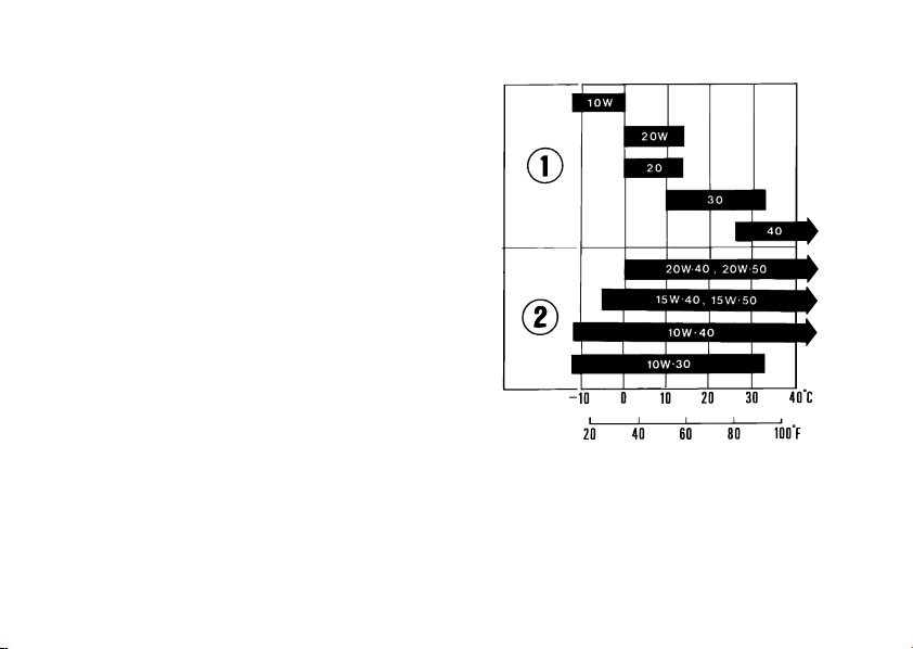
Viscosity:
Viscosity grade of engine oil should be
based on average atmospheric temperature
in your riding area. The f ollowing provides a
guide to the selection of the proper grade or
viscosity of oil to be used at various
atmospheric temperatures.
64
(1) Single grade (2) Multigrade
Page 75

Engine Oil
Engine oil quality is the chief factor
aff ecting engine service life. Change the
engine oil as specified in the maintenance
schedule (page ).
When running in very dusty conditions, oil
changes should be performed more
frequently than specified in the
maintenance schedule.
Please dispose of used engine oil in a
manner that is compatible with the
environment. We suggest you take it in a
sealed container to your local recycling
center or service station for reclamation. Do
not throw it in the trash or pour it on the
ground or down a drain.
Used engine oil may cause skin cancer if
repeatedly lef t in contact with the skin f or
prolonged periods. Although this is unlikely
unless you handle used oil on a daily basis,
it is still advisable to thoroughly wash your
handswithsoapandwaterassoonaspossible after handling used oil.
59
Changing the oil requires a torque wrench.
If you do not have it and the necessary skill,
we recommend that you have your Honda
dealer perform this service.
If a torque wrench is not used for this
installation, see your Honda dealer as soon
as possible to verify proper assembly.
Change the engine oil with the engine at
normal operating temperature and the
motorcycle on its center stand to assure
complete and rapid draining.
65
Page 76

1.
Place an oil drain pan under the
crankcase. Remove the oil filler cap/
dipstick, oil drain plug ( ) and sealing
washer ( ).
2.
After the engine oil has been drained out,
2
1
hold the motorcycle upright f or 10 15
seconds to assure complete draining.
3.
Operate the kickstarter several times to
aid in complete draining of the remaining
oil.
4.
Check that the sealing washer on the
(2)
drainplugisingoodconditionandinstall
the plug. Replace the sealing washer
every other time the oil is changed, or
each time if necessary.
Engine oil drain plug torque:
24 N·m (2.4 kgf·m , 17 lbf·ft)
5.
Fill the crankcase with the recommended
grade oil; approximately:
(0.8 US qt , 0.7 Imp qt)
0.8
−
6.
Reinstall the oil filler cap/dipstick.
7.
Start the engine and let it idle for 3 5
minutes.
8.
Stop the engine and wait 2 3 minutes.
−
Check that the oil level is at the upper
level mark on the oil filler cap/dipstick
with the motorcycle upright on f irm, level
ground.
Make sure there are no oil leaks
−
66
((22))
(1) Engine Oil drain plug
(2) Sealing washer
(1)
Page 77

ENGINE OIL STRAINER SCREEN
1.
To drain the oil, remove the oil filler cap/
dipstick and oil drain plug and sealing
washer (page ).
2.
Remove the oil strainer screen cap ( ),
spring ( ) and oil strainer screen ( ).
(1) Engine oil strainer screen cap
(2) Spring
(3) Engine oil strainer screen
66
2
(3)
3
(2)
(1)
3.
Wash the screen in clean solvent. Make
sure the sealing rubber and O-ring are in
good condition. Install the screen, spring
and cap.
1
Engine oil strainer screen cap torque:
15 N·m (1.5 kgf·m , 11 lbf·ft)
Check that the sealing washer on the
drainplugisingoodconditionandinstall
the plug. Replace the sealing washer
every other time the oil is changed, or
each time if necessary.
Engine oil drain plug torque:
24 N·m (2.4 kgf·m , 17 lbf·ft)
4.
Fill the crankcase with the recommended
grade oil; approximately:
(0.8 US qt , 0.7 Imp qt)
0.8
5.
Install the oil f iller cap/dipstick.
6.
Start the engine and let it idle for 3 5
−
minutes.
7.
2 3 minutes after stopping the engine,
−
check that the oil level is at the upper
level mark on the oil filler cap/dipstick
with the motorcycle upright on f irm, level
ground. Make sure there are no oil leaks.
67
Page 78
SPARK PLUG
Refer to the Safety Precautions on page .
57
Recommended plugs:
Standard:
−
DR8ES L (NGK)
For extended high speed riding:
DR8ES (NGK)
Never use a spark plug with an improper
heat range. Severe engine damage could
result.
68
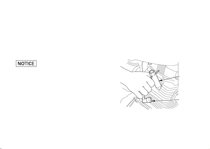
1.
Disconnect the spark plug cap ( ) from
1
the spark plug.
2.
Clean any dirt f rom around the spark plug
base.
Remove the spark plug using the spark
plug wrench ( ) furnished in the tool kit.
2
(2)
(1)
(1) Spark plug cap
(2) Spark plug wrench
Page 79
Inspect the electrodes and center
porcelain f or deposits, erosion or carbon
fouling. If the erosion or deposit is heavy,
replace the plug. Clean a carbon or wetfouled plug with a plug cleaner, otherwise
use a wire brush.
4.
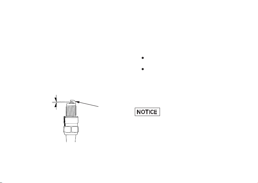
Checkthesparkpluggap( )usinga
3
wire-type feeler gauge. If adjustment is
necessary, bend the side electrode ( )
carefully.
The gap should be:
−−
0.60 0.70 mm (0.024 0.028 in)
(3)
(4)
(3) Spark plug gap
(4) Side electrode
5.3.
Make sure the plug washer is in good
condition.
6.
With the plug washer attached, thread
the spark plug in by hand to prevent
cross-threading.
7.
Tighten the spark plug:
If the old plug is good:
1/8 turn after it seats.
4
If installing a new plug, tighten it twice
to prevent loosening:
a)
First, tighten the plug:
NGK: turn after it seats.
b)
Then loosen the plug.
c)
Next, tighten the plug again:
3/4
1/8 turn after it seats.
Improperly tightened spark plug can
damage the engine. If a plug is too loose, a
pistonmaybedamaged.If aplugistootight,
thethreadsmaybedamaged.
8.
Reinstall the spark plug cap. Take care to
avoid pinching any cables or wires.
69
Page 80
VALVE CLEARANCE
Refer to the Safety Precautions on page .
Excessive valve clearance will cause noise
and eventual engine damage. Little or no
clearance will prevent the valve from
closing and cause valve damage and power
loss. Check valve clearance when the
engine is cold at the specified intervals.
The checking or adjusting of the clearance
should be performed while the engine is
cold. The clearance will change as the
engine temperature rises.
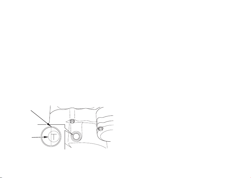
(1)
(2)
(1) Index mark
(2) T mark
70
Remove the crankshaft hole cap and
1.
timing mark hole cap.57
2.
Remove the cylinder head cover.
3.
Rotate the generator flywheel counterclockwise until the T mark ( ) on the
2
flywheel lines up with the index mark ( )
on the crankcase. In this position, the
piston may either be on the compression
or exhaust stroke.
The adjustment must be made when the
piston is at the top of the compression
stroke when both the intake and exhaust
valves are closed.
This condition can be determined by
moving the rocker arms. If they are free,
it is an indication that the valves are
closed and that the piston is on the
compression stroke. If they are tight and
the valves are open, rotate the flywheel
360° and realign the T mark to the index
mark.
1
Page 81

4.
Check the clearance of both valves by
inserting a f eeler gauge ( ) between the
adjusting screw ( ) and the valve stem.
3
5
Clearance should be:
Intake:
Exhaust:
0.08 mm (0.003 in)
0.08 mm (0.003 in)
If it is necessary to make an adjustment,
loosen the adjusting screw lock nut ( )
andturntheadjustingscrew( )sothere
3
is a slight resistance when the feeler
5
gauge ( ) is inserted.
5.
After completing the adjustment, tighten
the adjusting screw lock nut while
holding the adjusting screw to prevent it
from turning.
6.
Finally, recheck the clearance to make
sure that the adjustment has not been
disturbed. Reinstall the cylinder head
cover, timing mark hole cap and the
crankshaft hole cap.
(3)
(4)
4
(5)
(3) Adjusting screw
(4) Adjusting screw lock nut
(5) Feeler gauge
71
Page 82

THROTTLE OPERATION
Refer to the Safety Precautions on page .
1.
Check f or smooth rotation of the throttle
57
grip from the fully open to the fully
closed position at both full steering
positions.
2.
Measurethethrottlegripfreeplayatthe
throttle grip flange.
Thestandardfreeplayshouldbe
approximately:
−−
26mm(0.080.24in)
To adjust the freeplay, loosen the lock
nut ( ) and turn the adjuster ( ).
1
2
72
(1)
(2)
(1) Lock nut (2) Adjuster
Page 83
IDLE SPEED
Refer to the Safety Precautions on page .
57
The engine must be at normal operating
temperature f or accurate idle speed
adjustment. 10 minutes of stop-and-go riding
is sufficient.
Do not attempt to compensate for faults in
other systems by adjusting idle speed. See
your Honda dealer for regularly scheduled
carburetor adjustments.
1.
Warm up the engine, shift to neutral and
place the motorcycle on its center stand.
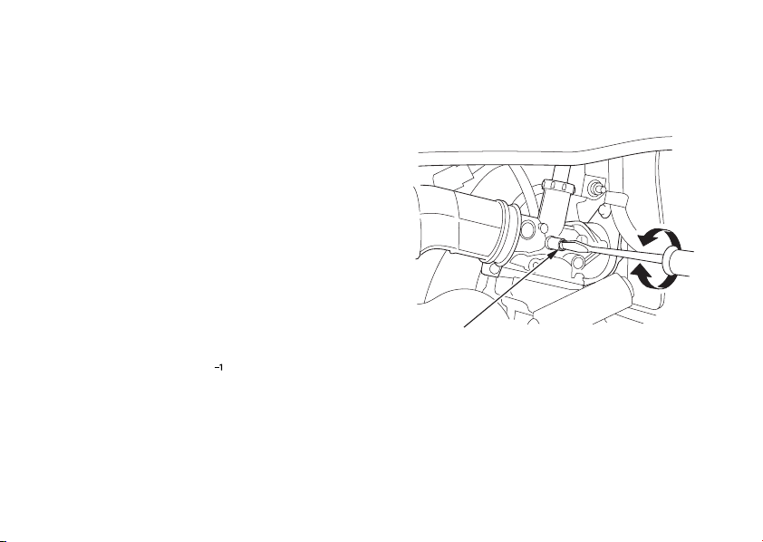
Adjust idle speed with the throttle stop
2.
screw ( ).
1
Idle speed (In neutral):
1,400 100 min
±
(rpm)
((BB))
((AA))
(1)
(1) Throttle stop screw (A) Increase
(B) Decrease
73
Page 84
AIR CLEANER
Refer to the Safety Precautions on page .
57
The air cleaner should be serviced at
regular intervals (page ). Service more
59
frequently when riding in unusually wet or
dusty areas.
1.
Remove the right side cover (page ).
2.
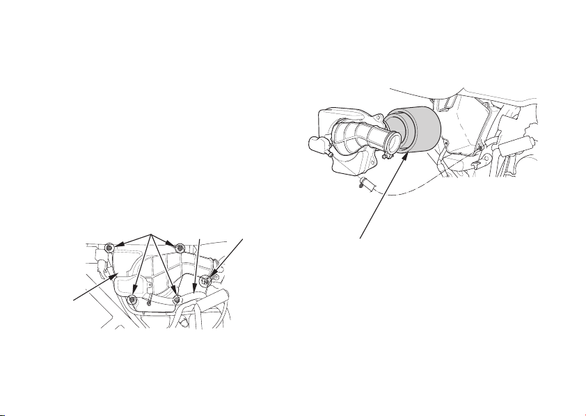
Disconnect the tube ( ).
3.
Remove the air cleaner housing cover ( )
1
by removing the screws A ( ) and loosen
the secrew B( ).
Pull out the air cleaner ( ).
4.
4
5
(3)
(1)
38
3
(4)
(2)
(1) Tube
(2) Air cleaner housing cover
(3) Screws A
(4) Screw B
74
2
(5)
(5) Air cleaner
Page 85

5.
Wash the air cleaner in clean, nonflammable or high flash point solvent and let it
dry thoroughly.
Never use petrol or low flash point solvents
for cleaning the air cleaner. A f ire or explosion could result.
6.
Soak the air cleaner in gear oil (SAE 80
90) until saturated, then squeeze out the
excess oil.
7.
Install the removed parts in the reverse
order of disassembly.
−
75
Page 86
DRIVE CHAIN
Refer to the Safety Precautions on page .
57
The service life of the drive chain is
dependent upon proper lubrication and
adjustment. Poor maintenance can cause
premature wear or damage to the drive
chain and sprockets.
The drive chain should be checked and
lubricated as part of the Pre-ride Inspection
42
(page ). Under severe usage, or when
the motorcycle is ridden in unusually dusty
or muddy areas, more frequent
maintenance will be necessary.
3.
Rotate the rear wheel. Stop. Check the
drive chain slack. Repeat this procedure
several times. Drive chain slack should
remain constant. If the chain is slack only
in certain sections, some links are kinked
and binding. Binding and kinking can
frequently be eliminated by lubrication.
Excessive chain slack may allow the drive
chain to damage the engine cases.
Inspection:
1.
Turn the engine off, place the motorcycle
on its center stand, and shift the
transmission into neutral.
2.
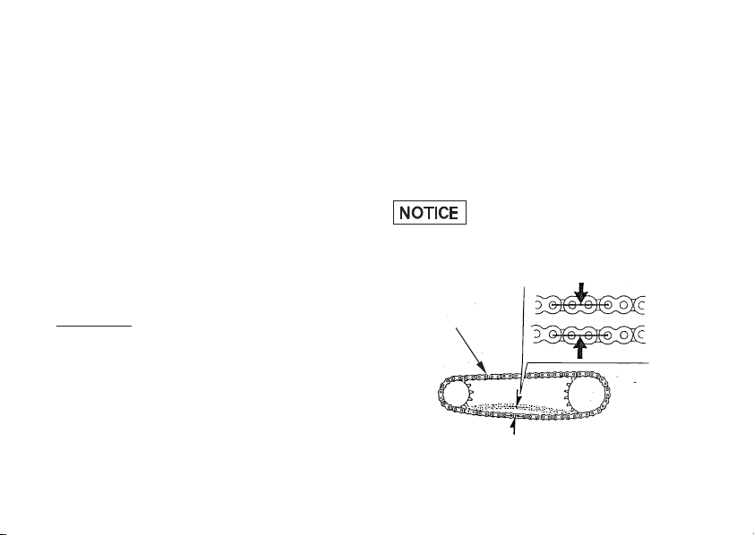
Check slack in the lower drive chain run
midway between the sprockets.
Drive chain slack should be adjusted to
allow the following vertical movement by
hand:
15 25 mm (0.6 1.0 in)
−−
76
(1)
(1) Drive chain
Page 87

4.
Inspect the sprocket teeth f or possible
wear or damage. Replace if necessary.
Damaged Sprocket
Teeth
REPLACE
Normal Sprocket Teeth
GOOD
If the drive chain or sprockets are
excessively worn or damaged, they should
be replaced. Never use a new chain with
worn sprockets; rapid chain wear will result.
Worn Sprocket
Teeth
REPLACE
77
Page 88
Adjustment:
Drive chain slack should be checked and
adjusted, if necessary, every 1,000 km (600
miles). When operated at sustained high
speeds or under conditions of frequent
rapid acceleration, the chain may require
more frequent adjustment.
If the drive chain requires adjustment, the
procedure is as follows:
1.
Place the motorcycle on its center stand
with the transmission in neutral and the
ignition switch of f.
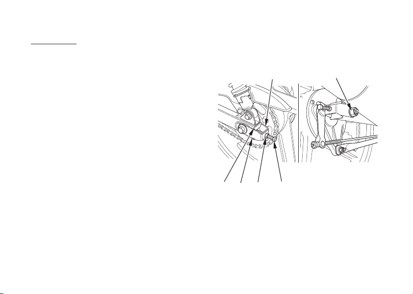
Loosen the rear axle nut ( ).
2.
Loosen the lock nuts ( ) on both
3.
adjusting bolts ( ).
3
1
2
78
(6)
(4) (2) (3)
(5)
(1) Rear axle nut
(2) Lock nut
(3) Drive chain adjusting bolt
(4) Rear end of the swingarm
(5) Corresponding scale
(6) Adjuster
(1)
Page 89

4.
Turn both adjusting bolts an equal
number of turns until the correct drive
chain slack is obtained. Turn the
adjusting bolts clockwise to tighten the
chain, or counterclockwise to provide
more slack. Adjust the chain slack at a
point midway between the drive sprocket
and the rear wheel sprocket. Rotate the
rear wheel and recheck slack at other
sections of the chain.
Chain slack should be:
15 25 mm (0.6 1.0 in)
−−
5.
Check the rear axle alignment by making
sure the rear end of the swingarm ( )
aligns with the corresponding scale ( )
on the adjuster ( ).
6
Both lef t and right swingarm ends should
align with the same mark on the
corresponding scale. If the axle is
misaligned, turn the left or right adjusting
bolt until the marks correspond.
Tighten the rear axle nut to the specif ied
6.
torque.
Rear axle nut torque:
59 N·m (6.0 kgf·m , 43 lbf·ft)
If a torque wrench is not used for this
installation, see your Honda dealer as soon
as possible to verify proper assembly.
7.
Tighten the adjusting bolts lightly, then
tighten the lock nuts by holding the
adjusting bolts with a spanner.
8.
Recheck drive chain slack.
9.
Rear brake pedal freeplay is affected
when repositioning the rear wheel to
adjust drive chain slack. Check rear brake
pedal freeplay and adjust as necessary
20
(page ).
4
5
Damage to the bottom part of the frame
maybecausedbyexcessivedrivechain
slack of more than:
50 mm (2.0 in)
79
Page 90

Lubrication:
Lubricate every 1,000 km (600 miles) or
sooner if chain appears dry.
Use SAE 80 or 90 gear oil or a commercially
prepared drive chain lubricants in
preference to motor oil or other lubricants.
Saturate each chain link joint so that the
lubricant penetrates between the link plates,
pins, bushings, and rollers.
Replacement chain:
428 108
−
80
Page 91

Removal and Cleaning:
When the drive chain becomes dirty, it
should be removed and cleaned prior to
lubrication.
1.
With the engine off, carefully remove the
master link retaining clip ( ) with a pair
1
of pliers. Do not bend or twist the clip.
Remove the master link. Remove the
drive chain from the motorcycle.
2.
Clean the drive chain in high flash-point
solvent and allow it to dry. Inspect the
drivechainforpossiblewearordamage.
Replace any chain that has damaged
rollers, loose fitting links, or otherwise
appears unserviceable.
Never use petrol or low flash point solvents
for cleaning the drive chain. A f ire or
explosion could result.
Inspect the sprocket teeth f or possible
3.
wear or damage. Replace if necessary.
Never use a new drive chain on badly worn
sprockets. Both chain and sprockets must
be in good condition, or the new
replacement chain or sprocket will wear
rapidly.
Lubricate the drive chain (page ).
4.
80
(1)
(1) Retaining clip
81
Page 92
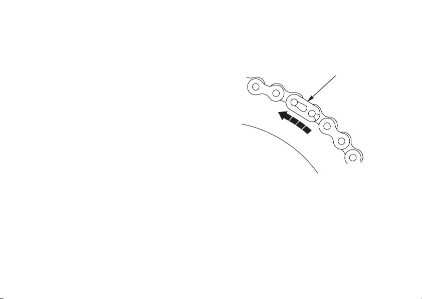
5.
Pass the chain over the sprockets and join
the ends of the chain with the master link.
For ease of assembly, hold the chain ends
against adjacent rear sprocket teeth while
inserting the master link.
The master link is the most critical part
aff ecting the security of the drive chain.
Master links are reusable, if they remain
in excellent condition, but it is
recommended that a new master link
retaining clip be installed whenever the
drive chain is reassembled.
Install the master link retaining clip so
that the closed end of the clip will face
the direction of forward wheel rotation.
6.
Adjust the drive chain (page ) and
rear brake pedal freeplay (page ).
78
20
82
(1)
(1) Retaining clip
Page 93

FRONT AND REAR SUSPENSION
INSPECTION
Refer to the Safety Precautions on page .
1.
Check the fork assembly by locking the
front brake and pumping the fork up and
down vigorously. Suspension action
should be smooth and there must be no
oil leakage.
2.
Swingarm bushings should be checked
by pushing hard against the side of the
rear wheel while the motorcycle is on the
center stand and f eeling for looseness of
the bushings.
3.
Carefully inspect all front and rear
suspension fasteners for tightness.
57
83
Page 94
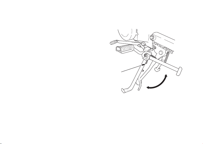
SIDE STAND
Refer to the Safety Precautions on page .
57
Checkthesidestandspring( )fordamage
1
and loss of tension, and the side stand
assembly for freedom of movement.
Ifthesidestandissqueakyorstiff,clean
the pivot area and lubricate the pivot bolt
with clean engine oil.
84
(1)
(1) Side stand spring
Page 95

WHEEL REMOVAL
Refer to the Safety Precautions on page .
Front Wheel Removal
1.
Raise the front wheel off the ground by
(Type , )
57
placing a support block under the engine.
2.
Remove the speedometer cable clip ( ).
3.
Pull out the speedometer cable ( ).
4.
Remove the front brake adjusting nut ( )
and remove the front brake cable ( )
from the brake arm ( ).
5.
Remove the front axle nut ( ).
5
6
Remove the front axle shaf t ( ) and the
1
2
3
4
7
wheel.
(7)
(5)
(3)
(2)
(4)
(1)
(6)
(1) Speedometer cable clip
(2) Speedometer cable
(3) Brake adjusting nut
(4) Front brake cable
(5) Brake arm
(6) Front axle nut
(7) Front axle shaft
85
Page 96

Installation Notes:
Reverse the removal procedure.
Position the front wheel between the fork
legs and insert the front axle shaft from
the left side, through the left fork leg and
wheel hub.
Make sure that the tang ( ) on the left
8
front fork leg is located in the brake panel.
Tighten the front axle nut to the specified
torque.
Front axle nut torque:
52 N·m (5.3 kgf·m , 38 lbf·ft)
Adjust the front brake f reeplay (pages
).
1816
−
After installing the wheel, apply the brake
several times and check for free wheel
rotation when released.
86
If a torque wrench was not used for
installation, see your Honda dealer as soon
as possible to verify proper assembly.
Improper assembly may lead to loss of
braking capacity.
(8)
(8) Tang
Page 97
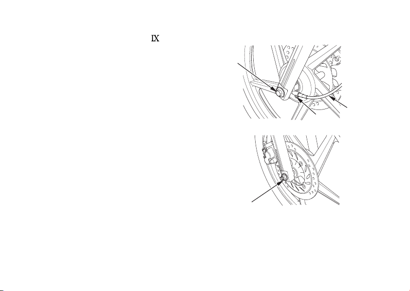
Front Wheel Removal (Type )
Refer to the Safety Precautions on page .
Raise the front wheel off the ground by
1.
57
placing a support block under the engine.
2.
Remove the speedometer cable ( ) by
removing the screw ( ).
3.
Remove the front axle nut ( ).
4.
Remove the front axle shaf t ( ) and the
2
1
3
4
wheel.
Do not depress the brake lever when the
wheel is off the motorcycle. The caliper
piston will be forced out of the cylinder with
subsequent loss of brake f luid. If this occurs,
servicing of the brake system will be
necessary. See your Honda dealer f or this
service.
(4)
(3)
(2)
(1)
(1) Speedmeter cable
(2) Screw
(3) Front axle nut
(4) Front axle shaft
87
Page 98
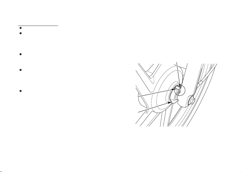
Installation Notes:
Reverse the removal procedure.
Position the front wheel between the fork
legs and insert the front axle shaft from
the left side, through the left fork leg and
wheel hub.
Make sure that the lug ( ) on the left
fork leg is located in the slot ( ) of the
speedometer gearbox ( ).
5
6
7
Tighten the front axle nut to the specified
torque.
Front axle nut torque:
52 N·m (5.3 kgf·m , 38 lbf·ft)
To avoid damaging the brake pads while
installing the wheel, carefully fit the
brake disc between the pads.
After installing the wheel, apply the brake
several times and check for free wheel
rotation when released.
88
If a torque wrench was not used for
installation, see your Honda dealer as soon
as possible to verify proper assembly.
Improper assembly may lead to loss of
braking capacity.
(5)
((66))
(7)
(5) Lug (7) Speedmeter gearbox
(6) Slot
Page 99
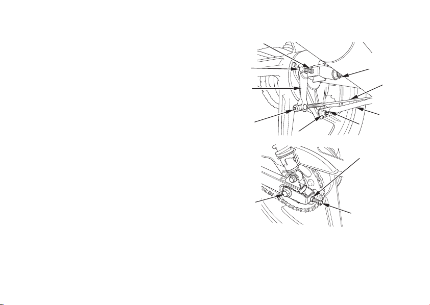
Rear Wheel Removal
Refer to the Safety Precautions on page .
1.
Place the motorcycle on its center stand.
2.
Remove the rear brake adjusting nut ( ).
Disconnect the brake rod ( ) from the
brake arm ( ).
3.
Disconnect the brake stopper arm ( )
3
2
57
1
4
from the brake panel by removing the
cotter pin ( ), stopper arm nut ( ),
56
washer and rubber grommet.
Loosen the drive chain lock nuts ( ) and
4.
adjusting bolts ( ).
Remove the rear axle nut ( ) and pull out
5.
therearaxleshaft( ).
8
9
10
7
Push the wheel forward and remove the
drive chain from the rear sprocket.
Pull out the wheel from the swingarm.
6.
(8)
(3)
(1)
(10)
(7)
(9)
(2)
(4)
((55))
((66))
(7)
((88))
(1) Brake adjusting nut
(2) Brake rod
(3) Brake arm
(4) Brake stopper arm
(5) Cotter pin
(6) Stopper arm nut
(7) Lock nuts
(8) Adjusting bolts
(9) Rear axle nut
(10) Rear axle shaft
89
Page 100

Installation Notes:
Reverse the removal procedure.
Tighten the rear axle nut and brake
stopper arm nut to specified torque.
Rear axle nut torque:
59 N·m (6.0 kgf·m , 43 lbf·ft)
Brake stopper arm nut torque:
22 N·m (2.2 kgf·m , 16 lbf·ft)
Adjust the brake (page ) and drive
chain (page ).
After installing the wheel, apply the
brakes several times, and check for free
wheel rotation when released.
If a torque wrench was not used for
installation, see your Honda dealer as soon
as possible to verify proper assembly.
Improper assembly may lead to loss of
braking capacity.
Used cotter pin may not effectively secure
fastener. Always replace used cotter pin
with new one.
90
78
20
 Loading...