

Page 1
Page 2

This manual should be considered a permanent part of the vehicle
and should remain with the vehicle when it is resold.
This publication includes the latest production information available
before printing. Honda Motor Co., Ltd. reserves the right to make
changes at any time without notice and without incurring any
obligation.
No part of this publication may be reproduced without written
permission.
The vehicle pictured in this owner’s manual may not match your
actual vehicle.
© 2020 Honda Motor Co., Ltd.
Page 3
Welcome
Congratulations on your purchase of a new
Honda vehicle. Your selection of a Honda
makes you part of a worldwide family of
satisfied customers who appreciate Honda's
reputation for building quality into every
product.
To ensure your safety and riding pleasure:
● Read this owner's manual carefully.
● Follow all recommendations and
procedures contained in this manual.
● Pay close attention to safety messages
contained in this manual and on the
vehicle.
● The following codes in this manual
indicate each country.
● The illustrations here in are based on the
CBR600R3 GS type.
Country Codes
Code
Country
CBR600R3
GS GCC Countries
IN Indonesia
MA Malaysia
U Australia, New Zealand
*The specifications may vary with each locale.
Page 4
A Few Words About Safety
Your safety, and the safety of others, is very
important. Operating this vehicle safely is an
important responsibility.
To help you make informed decisions about
safety, we have provided operating
procedures and other information on safety
labels and in this manual. This information
alerts you to potential hazards that could
hurt you or others.
Of course, it is not practical or possible to
warn you about all hazards associated with
operating or maintaining a vehicle. You must
use your own good judgement.
You will find important safety information in a
variety of forms, including:
● Safety labels on the vehicle
●
Safety Messages preceded by a safety alert
symbol and one of three signal words:
DANGER, WARNING, or CAUTION.
These signal words mean:
3DANGER
You WILL be KILLED or SERIOUSLY
HURT if you don’t follow instructions.
3WARNING
You CAN be KILLED or SERIOUSLY
HURT if you don’t follow instructions.
3CAUTION
You CAN be HURT if you don’t follow
instructions.
Other important information is
provided under the following titles:
NOTICE
Information to help you avoid
damage to your vehicle, other
property, or the environment.
Page 5
Contents
Vehicle Safety
Operation Guide
Maintenance
Troubleshooting
Information
Specifications
P. 2
P. 20
P. 101
P. 145
P. 156
P. 170
Page 6

Vehicle Safety
This section contains important information for safe riding of your vehicle.
Please read this section carefully.
Safety Guidelines................................................. P. 3
Image Labels......................................................... P. 7
Safety Precautions............................................. P. 12
Riding Precautions ............................................ P. 13
Accessories & Modifications........................... P. 17
Loading ................................................................ P. 18
Page 7
Safety Guidelines
Safety Guidelines
Follow these guidelines to enhance your safety:
● Perform all routine and regular inspections
specified in this manual.
● Stop the engine and keep sparks and flame
away before filling the fuel tank.
● Do not run the engine in enclosed or partly
enclosed areas. Carbon monoxide in
exhaust gases is toxic and can kill you.
Always Wear a Helmet
It's a proven fact: helmets and protective
apparel significantly reduce the number and
severity of head and other injuries. So always
wear an approved helmet and protective
apparel. 2 P. 12
Before Riding
Make sure that you are physically fit, mentally
focused and free of alcohol and drugs. Check
that you and your passenger are both wearing
an approved helmet and protective apparel.
Instruct your passenger on holding onto the
seat strap or your waist, leaning with you in
turns, and keeping their feet on the footpegs,
even when the vehicle is stopped.
Take Time to Learn & Practice
Even if you have ridden other vehicles, practice
riding in a safe area to become familiar with
how this vehicle works and handles, and to
become accustomed to the vehicle's size and
weight.
Continued
Vehicle Safety
3
Page 8
Safety Guidelines
Ride Defensively
Vehicle Safety
Always pay attention to other vehicles around
you, and do not assume that other drivers see
you. Be prepared to stop quickly or perform an
evasive maneuver.
Make Yourself Easy to See
Make yourself more visible, especially at night,
by wearing bright reflective clothing, positioning
yourself so other drivers can see you, signaling
before turning or changing lanes, and using
your horn when necessary.
4
Ride within Your Limits
Never ride beyond your personal abilities or
faster than conditions warrant. Fatigue and
inattention can impair your ability to use good
judgement and ride safely.
Don't Drink or Use Drugs and Ride
Alcohol or drugs and riding don't mix. Even one
alcoholic drink can reduce your ability to
respond to changing conditions, and your
reaction time gets worse with every additional
drink. The same is true for drug use. Don't drink
or use and ride, and don't let your friends do it
either.
Page 9
Safety Guidelines
Keep Your Honda in Safe Condition
It's important to keep your vehicle properly
maintained and in safe riding condition.
Inspect your vehicle before every ride and
perform all recommended maintenance. Never
exceed load limits (2 P. 18), and do not modify
your vehicle or install accessories that would
make your vehicle unsafe (2 P. 17).
If You are Involved in a Crash
Personal safety is your first priority. If you or
anyone else has been injured, take time to
assess the severity of the injuries and whether it
is safe to continue riding. Call for emergency
assistance if needed. Also follow applicable laws
and regulations if another person or vehicle is
involved in the crash.
If you decide to continue riding, first turn the
ignition switch to the (Off) position, and
evaluate the condition of your vehicle. Inspect
for fluid leaks, check the tightness of critical nuts
and bolts, and check the handlebars, control
levers, brakes, and wheels. Ride slowly and
cautiously.
Your vehicle may have suffered damage that is
not immediately apparent. Have your vehicle
thoroughly checked at a qualified service facility
as soon as possible.
Continued
Vehicle Safety
5
Page 10
Safety Guidelines
Carbon Monoxide Hazard
Vehicle Safety
Exhaust contains poisonous carbon monoxide, a
colourless, odorless gas. Breathing carbon
monoxide can cause loss of consciousness and
may lead to death.
If you run the engine in confined or even partly
enclosed area, the air you breathe could
contain a dangerous amount of carbon
monoxide.
Never run your vehicle inside a garage or other
enclosure.
6
3WARNING
Running the engine of your vehicle
while in an enclosed or even partially
enclosed area can cause a rapid buildup of toxic carbon monoxide gas.
Breathing this colourless, odorless gas
can quickly cause unconsciousness and
lead to death.
Only run your vehicle's engine when it
is located in a well ventilated area
outdoors.
Page 11
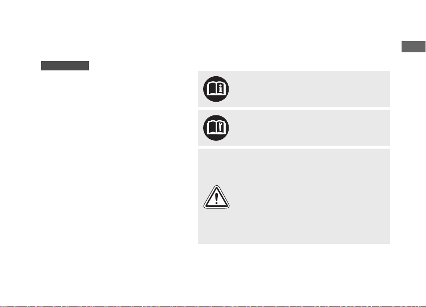
Image Labels
Image Labels
GS, IN, U type
The following pages describe the label
meanings. Some labels warn you of
potential hazards that could cause serious
injury. Others provide important safety
information. Read this information carefully
and don't remove the labels.
If a label comes off or becomes hard to
read, contact your dealer for a replacement.
There is a specific symbol on each label.
The meanings of each symbol and label are
as follows.
Read instructions contained in Owner's
Manual carefully.
Read instructions contained in Shop Manual
carefully. In the interest of safety, take the
vehicle to be serviced only by your dealer.
DANGER (with RED background)
You WILL be KILLED or SERIOUSLY HURT if
you don't follow instructions.
WARNING (with ORANGE background)
You CAN be KILLED or SERIOUSLY HURT if
you don't follow instructions.
CAUTION (with YELLOW background)
You CAN be HURT if you don't follow
instructions.
Continued
Vehicle Safety
7
Page 12
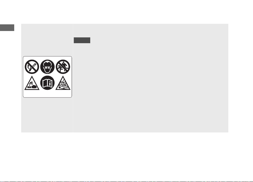
Image Labels
Vehicle Safety
8
BATTERY LABEL
DANGER
GS type
• Keep flame and spark away from the battery. Battery produce
explosive gas that can cause explosion.
• Wear the eye protection and rubber gloves when handling the battery,
or you can get burned or lose your eyesight by the battery electrolyte.
• Do not allow children and other people to touch a battery unless they
understand proper handling and hazards of the battery very well.
• Handle the battery electrolyte with extreme care as it contains dilute
sulfuric acid. Contact with your skin or eyes can burn you or cause loss
of your eyesight.
Read this manual carefully and understand it before handling the
•
battery. Neglect of the instructions can cause personal injury and
damage to the vehicle.
Do not use a battery with the electrolyte at or below the lower level
•
mark. It can explode causing serious injury.
Page 13
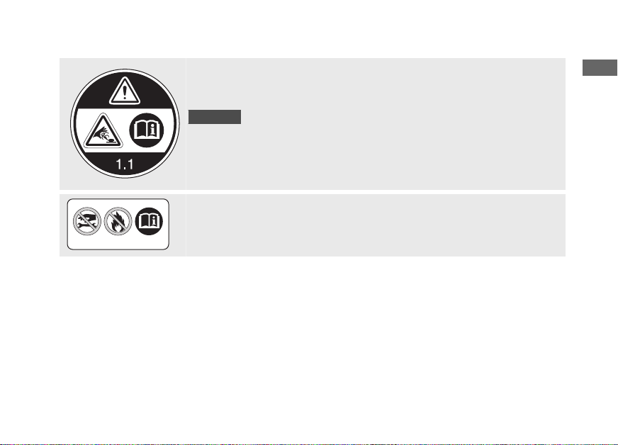
Image Labels
RADIATOR CAP LABEL
DANGER
GS, U type
NEVER OPEN WHEN HOT.
Hot coolant will scald you.
Relief pressure valve begins to open at 1.1 kgf/cm2.
REAR CUSHION LABEL
GAS FILLED
Do not open. Do not heat.
Continued
Vehicle Safety
9
Page 14
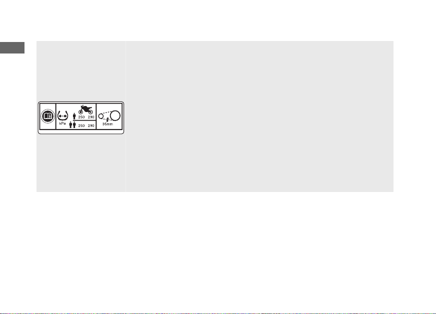
Image Labels
Vehicle Safety
10
TYRE INFORMATION & DRIVE CHAIN LABEL
Cold tyre pressure:
[Driver only]
Front
250 kPa (2.50 kgf/cm2, 36 psi)
Rear
290 kPa (2.90 kgf/cm2, 42 psi)
[Driver and passenger]
Front
250 kPa (2.50 kgf/cm2, 36 psi)
Rear
290 kPa (2.90 kgf/cm2, 42 psi)
Keep chain adjusted and lubricated.
Freeplay 30 - 40 mm (1.2 - 1.6 in)
Page 15
Image Labels
GS type
U type
SAFETY REMINDER LABEL
GS, U type
For your protection, always wear helmet, protective apparel.
GS type
FUEL LABEL
Unleaded petrol only
ETHANOL up to 10 % by volume
Premium Recommended
U type
FUEL LABEL
Unleaded petrol only
ETHANOL up to 10 % by volume
Research Octane Number (RON) 95 or higher
Vehicle Safety
11
Page 16
Safety Precautions
Safety Precautions
Vehicle Safety
● Ride cautiously and keep your hands on the
handlebars and feet on the footpegs.
● Keep passenger's hands onto the seat strap
or your waist, passenger's feet on the
footpegs while riding.
Always consider the safety of your
●
passenger, as well as other drivers and
riders.
Protective Apparel
Make sure that you and any passenger are
wearing an approved helmet, eye protection,
and high-visibility protective clothing. Avoid
wearing loose clothes that could get caught on
any part of the vehicle. Ride defensively in
response to weather and road conditions.
Helmet
#
Safety-standard certified, high-visibility, correct
size for your head
● Must fit comfortably but securely, with the
chin strap fastened.
12
● Face shield with unobstructed field of vision
or other approved eye protection
3WARNING
Not wearing a helmet increases the
chance of serious injury or death in a
crash.
Make sure that you and any passenger
always wear an approved helmet and
protective apparel.
Gloves
#
Full-finger leather gloves with high abrasion
resistance
Boots or Riding Shoes
#
Sturdy boots with non-slip soles and ankle
protection
Jacket and Trousers
#
Protective, highly visible, long-sleeved jacket
and durable trousers for riding (or a protective
suit)
Page 17
Riding Precautions
Riding Precautions
Running-in Period
During the first 500 km (300 miles) of running,
follow these guidelines to ensure your vehicle's
future reliability and performance.
● Avoid full-throttle starts and rapid
acceleration.
● Avoid hard braking and rapid down-shifts.
● Ride conservatively.
Brakes
Observe the following guidelines:
●
Avoid excessively hard braking and
downshifting.
u Sudden braking can reduce the vehicle's
stability.
u Where possible, reduce speed before
turning; otherwise you risk sliding out.
● Exercise caution on low traction surfaces.
u The tyres slip more easily on such
surfaces and braking distances are
longer.
● Avoid continuous braking.
u Repeated braking, such as when
descending long, steep slopes can
seriously overheat the brakes, reducing
their effectiveness. Use engine braking
with intermittent use of the brakes to
reduce speed.
● For full braking effectiveness, operate both
the front and rear brakes together.
Continued
Vehicle Safety
13
Page 18

Riding Precautions
Anti-lock Brake System (ABS)
#
Vehicle Safety
This model is equipped with an Anti-lock Brake
System (ABS) designed to help prevent the
brakes from locking up during hard braking.
The ABS functions with information provided by
the IMU (Inertia Measurement Unit).
● ABS does not reduce braking distance. In
certain circumstances, ABS may result in a
longer stopping distance.
● ABS does not function at speeds below 6
km/h (4 mph).
● The brake lever and pedal may recoil slightly
when applying the brakes. This is normal.
● Always use the recommended front/rear
tyres and sprockets to ensure correct ABS
operation.
14
Engine Braking
#
Engine braking helps slow your vehicle down
when you release the throttle. For further
slowing action, downshift to a lower gear. Use
engine braking with intermittent use of the
brakes to reduce speed when descending long,
steep slopes.
Wet or Rainy Conditions
#
Road surfaces are slippery when wet, and wet
brakes further reduce braking efficiency.
Exercise extra caution when braking in wet
conditions.
If the brakes get wet, apply the brakes while
riding at low speed to help them dry.
Page 19
Parking
● Park on a firm, level surface.
● If you must park on a slight incline or loose
surface, park so that the vehicle cannot
move or fall over.
● Make sure that high-temperature parts
cannot come into contact with flammable
materials.
● Do not touch the engine, muffler, brakes
and other high-temperature parts until they
cool down.
● To reduce the likelihood of theft, always lock
the handlebars and remove the key when
leaving the vehicle unattended.
Use of an anti-theft device is also
recommended.
Parking with the Side Stand
#
1.
Stop the engine.
2.
Push the side stand down.
Riding Precautions
3.
Slowly lean the vehicle to the left until its
weight rests on the side stand.
4.
Turn the handlebars fully to the left.
u Turning the handlebars to the right
reduces stability and may cause the
vehicle to fall.
5.
Turn the ignition switch to the (Lock)
position and remove the key. 2 P. 86
Refuelling and Fuel Guidelines
Follow these guidelines to protect the engine,
fuel system and catalytic converter:
● Use only unleaded petrol.
● Use recommended octane number. Using
lower octane petrol will result in decreased
engine performance.
● Do not use fuels containing a high
concentration of alcohol. 2 P. 168
● Do not use stale or contaminated petrol or
an oil/petrol mixture.
● Avoid getting dirt or water in the fuel tank.
Vehicle Safety
Continued
15
Page 20
Riding Precautions
Honda selectable torque control
Vehicle Safety
When the Honda selectable torque control
(Torque Control) detects rear wheel spin during
acceleration, the system will limit the amount of
torque applied to the rear wheel based on the
Torque Control level selected.
Additionally, the system ease the rapid motion
during accelerating based on the Wheelie
Control level selected.
Torque Control will allow some wheel spin
during acceleration at the lower Torque Control
levels settings. Select a level that is appropriate
for your skill and riding conditions.
Torque Control does not work during
deceleration and will not prevent the rear wheel
from skidding due to engine braking. Do not
close the throttle suddenly, especially when
riding on slippery surfaces.
16
Torque Control may not compensate for rough
road conditions or rapid throttle operation.
Always consider road and weather conditions,
as well as your skills and condition, when
applying throttle.
If your vehicle gets stuck in mud, snow or sand,
it may be easier to free it by turning off the
Torque Control temporarily.
Temporarily turning off Torque Control also
may help you maintain control and balance
when riding on off-road terrain.
Always use the recommended tyres and
sprockets to ensure correct Torque Control
operation.
Page 21

Accessories & Modifications
Accessories &
Modifications
We strongly advise that you do not add any
accessories that were not specifically designed
for your vehicle by Honda or make
modifications to your vehicle from its original
design. Doing so can make it unsafe.
Modifying your vehicle may also void your
warranty and make your vehicle illegal to
operate on public roads. Before deciding to
install accessories on your vehicle be certain the
modification is safe and legal.
3WARNING
Improper accessories or modifications
can cause a crash in which you can be
seriously hurt or killed.
Follow all instructions in this owner's
manual regarding accessories and
modifications.
Do not pull a trailer with, or attach a sidecar to,
your vehicle. Your vehicle was not designed for
these attachments, and their use can seriously
impair your vehicle's handling.
Vehicle Safety
17
Page 22

Loading
Loading
Vehicle Safety
● Carrying extra weight affects your vehicle's
handling, braking and stability.
Always ride at a safe speed for the load you
are carrying.
● Avoid carrying an excessive load and keep
within specified load limits.
Maximum weight capacity 2 P. 170
● Tie all luggage securely, evenly balanced
and close to the centre of the vehicle.
● Do not place objects near the lights or the
muffler.
18
3WARNING
Overloading or improper loading can
cause a crash and you can be seriously
hurt or killed.
Follow all load limits and other loading
guidelines in this manual.
Page 23

Vehicle Safety
19
Page 24
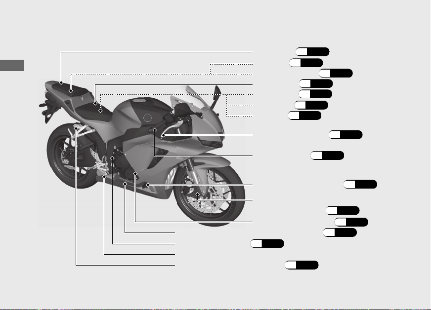
Parts Location
Operation Guide
20
Rear seat (P.124)
Tool kit (P.100)
Document bag (P.100)
Front seat (P.122)
Main fuse (P.155)
Fuse box (P.154)
Battery (P.120)
Front brake lever (P.138)
Throttle grip (P.137)
Coolant reserve tank (P.127)
Front suspension spring
preload adjuster
Right middle Cowl (P.123)
Engine oil level inspection window (P.125)
Engine oil fill cap (P.125)
Rear brake pedal
Rear brake fluid reservoir (P.129)
(P.139
)
Page 25
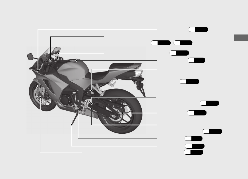
Clutch lever (P.134)
Front suspension rebound damping/compression
damping adjusters
(P.140
)
(P.141
)
Front brake fluid reservoir (P.129)
Fuel fill cap (P.98)
Rear suspension
compression damping
adjuster
(P.144
)
Rear suspension spring
preload adjuster
Drive chain (P.133)
Rear suspension rebound
damping adjuster
Shift lever (P.95)
Side stand (P.132)
Front suspension spring preload adjuster (P.139)
(P.142
(P.143
Operation Guide
)
)
21
Page 26
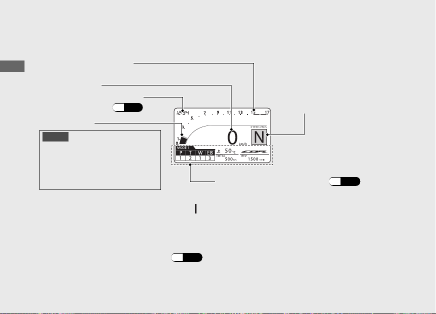
Instruments
Street mode
Tachometer red zone
Operation Guide
(excessive engine rpm range)
Speedometer
Clock (12-hour display)
To set the clock:
(P.61
)
Tachometer
NOTICE
Do not operate the engine in the
tachometer red zone. Excessive
engine speed can adversely affect
engine life.
Multi-information display (P.24)
Display Check
When the ignition switch is turned to the (On) position, the opening symbol will show on
the display. If the display itself does not shows when it should, have your dealer check for
problems.
You can select the street mode or circuit mode display.
To change to the circuit mode:
22
(P.23
)
Gear position indicator
Shows 1st to 6th gear
positions. “-”appears when
the transmission is not shifted
properly.
Page 27
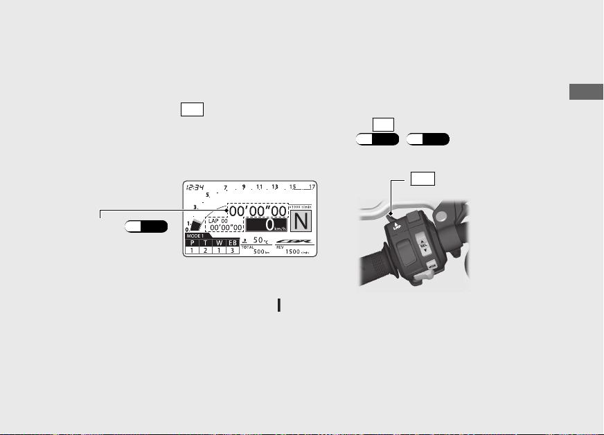
Circuit mode
To change to the circuit mode :
● Press and hold the
u To return to the street mode display, press and hold the
● Select the “CIRCUIT” menu on the “DISPLAY” screen. (P.42) (P.50)
LAP
button with your vehicle stopped.
LAP
button.
u To return to the street mode display, select the “STREET” menu on the “DISPLAY”.
LAP
button
Lap timer (P.74)
Display Check
When the ignition switch is turned to the (On) position, the opening symbol will show on
the display. If the display itself does not shows when it should, have your dealer check for
problems.
Continued
Operation Guide
23
Page 28
Instruments (Continued)
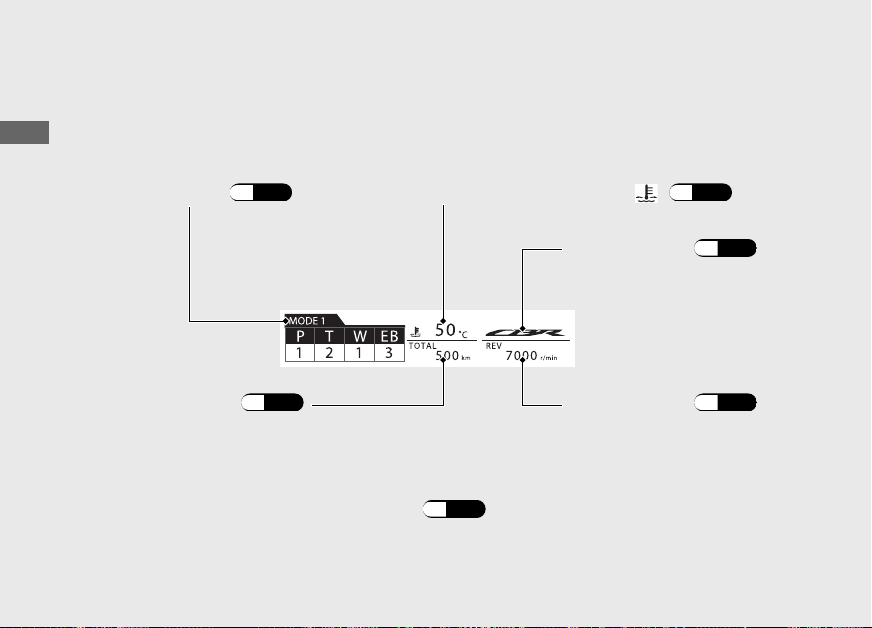
Multi-information display
Multi-information display can display the coolant temperature gauge, riding modes, INFO 1,
Operation Guide
INFO 2 and INFO 3 displays.
Riding mode (P.87)
Coolant temperature gauge ( ) (P.25)
INFO 3 display (P.38)
INFO 2 display (P.30)INFO 1 display (P.27)
You can change the riding mode, INFO1, INFO 2 and INFO 3 displays of the Multiinformation display.
To switch the multi-information display: (P.26)
24
Page 29
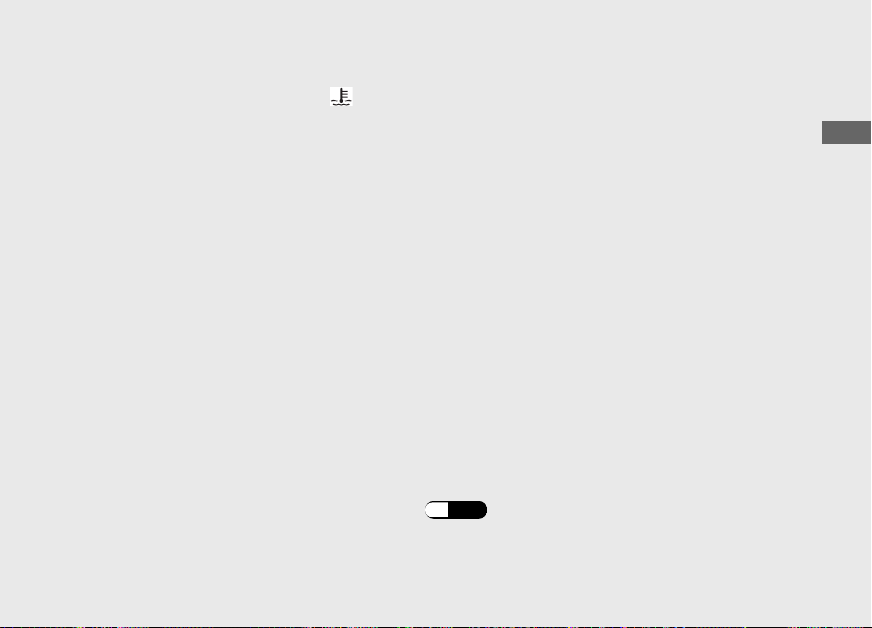
Coolant temperature gauge ( )
Display range: 35°C to 132°C
● 34°C or less: ”---” is displayed.
● Between 122°C and 131°C:
-
High coolant temperature indicator lights.
-
Coolant temperature digits flash.
● Above 132°C:
-
High coolant temperature indicator lights.
-
“132°C” flashes.
● Even if the engine coolant temperature is low, the cooling fan may start running when you
rev up the engine. This is normal.
Pop-up information
In the following cases, the INFO 3 display, or the INFO 3 display and the coolant temperature
gauge change to a pop-up information display.
● When an inspection time of your vehicle is approaching.
● When your vehicle has helpful information.
● When your vehicle has a problem with the PGM-FI system.
Information of the pop-up information: (P.78)
Operation Guide
Continued
25
Page 30
Instruments (Continued)
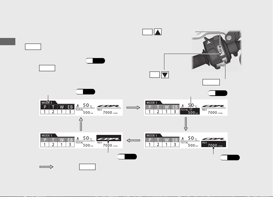
To switch the multi-information display
To select the display area, repeatedly press the
Operation Guide
MODE
button.
u Can not select the INFO 3 display while pop-up
information displayed. (P.78)
MODE
If the
seconds, the display returns to the riding mode
display.
button is not pressed within 10
Riding mode (P.87)
SEL
(up) button
SEL
(down)
button
INFO 1 display (P.27)
MODE
button
26
Press the
INFO 3 display (P.38)
MODE
button
INFO 2 display (P.30)
Page 31
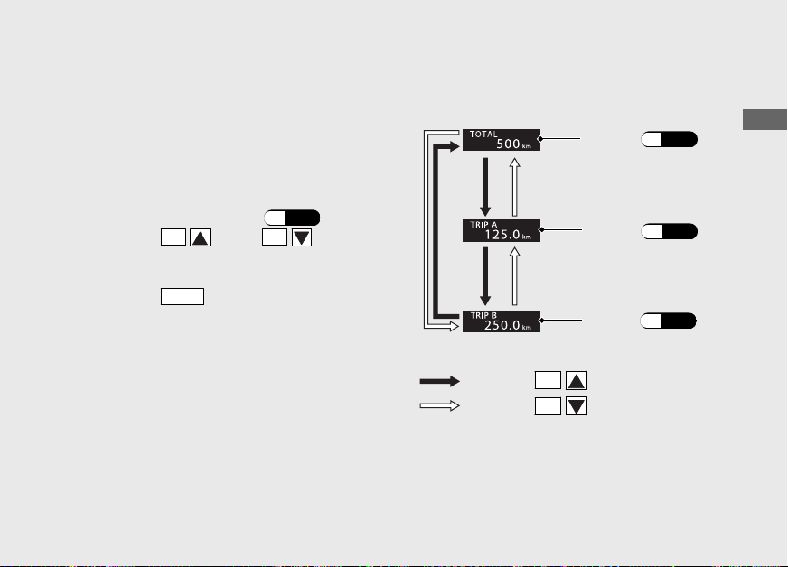
INFO 1 display
You can select the following:
• Odometer [TOTAL]
• Tripmeter [TRIP A/B]
Changing the INFO 1 display
a
Select the INFO 1 display. (P.26
b
Press the
SEL
(up) or
SEL
(down)
button until the desired indication is
displayed.
c
Press the
MODE
button. The INFO 1 display
is set, and then the display moves to the
INFO 2 display.
TOTAL (P.28)
)
TRIP A (P.28)
Operation Guide
TRIP B (P.28)
Press the
Press the
SEL
(up) button
SEL
(down) button
Continued
27
Page 32
Instruments (Continued)
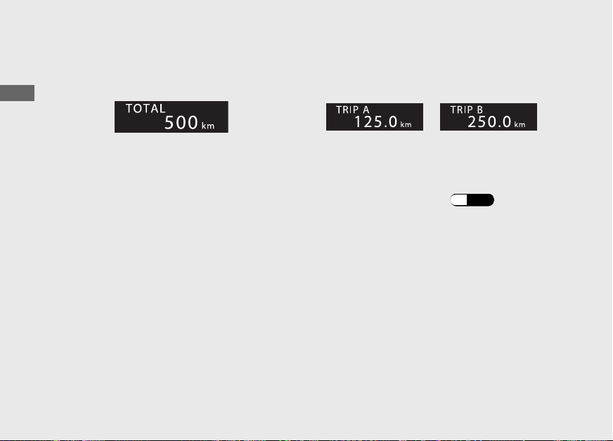
Odometer [TOTAL]
Total distance ridden.
Operation Guide
Tripmeter A/B [TRIP A/B]
Distance ridden since the tripmeter was reset.
When “------” is displayed, go to your dealer
for service.
28
When “----.-” is displayed, go to your dealer
for service.
To reset the tripmeter:
(P.29)
Page 33
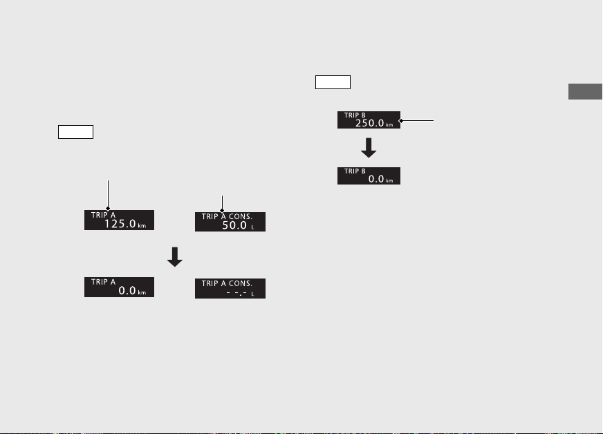
To Reset the Tripmeter and Tripmeter
#
A Fuel Consumption
To reset tripmeter A and tripmeter A fuel
consumption together, press and hold the
MODE
button with the tripmeter A or
tripmeter A fuel consumption displayed.
Tripmeter A Tripmeter A fuel
consumption
or
or
To reset the tripmeter B, press and hold the
MODE
button with the tripmeter B displayed.
Tripmeter B
Operation Guide
Continued
29
Page 34
Instruments (Continued)
INFO 2 display
You can select the following:
Operation Guide
• Numerical tachometer display [REV]
• Current fuel mileage [INST. CONS.]
• Average fuel mileage [AVE. CONS.]
• Tripmeter A fuel consumption [TRIP A CONS.]
• Average speed [AVG. SPD.]
• Elapsed time [ELAPSED]
• Available riding distance [RANGE]
(Only when reserve fuel mode)
• Amount of remaining fuel [REMAIN]
(Only when reserve fuel mode)
Changing the INFO 2 display
a
Select the INFO 2 display. (P.26
30
b
Press the
c
Press the
SEL
(up) or
MODE
button. The INFO 2 display is set, and display moves to the INFO 3 display.
SEL
(down) button until the desired display is displayed.
)
Page 35
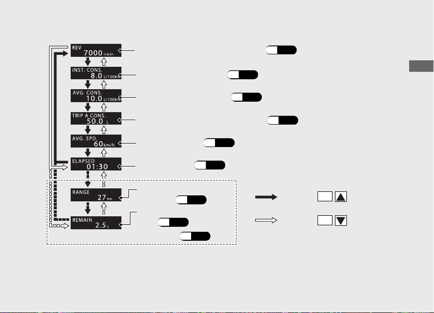
Numerical tachometer display (P.32)
Current fuel mileage (P.32)
Average fuel mileage (P.33)
Tripmeter A fuel consumption (P.34)
Average speed (P.34)
Elapsed time (P.35)
Available riding
distance
(P.35
)
Amount of remaining
fuel
(P.36
)
Only when reserve fuel mode: (P.37)
Press the
button
Press the
button
SEL
(up)
SEL
(down)
When the low fuel indicator lights and the low fuel pop-up information appear, INFO 3 display
will automatically switches to the amount of remaining fuel display.
Continued
Operation Guide
31
Page 36
Instruments (Continued)
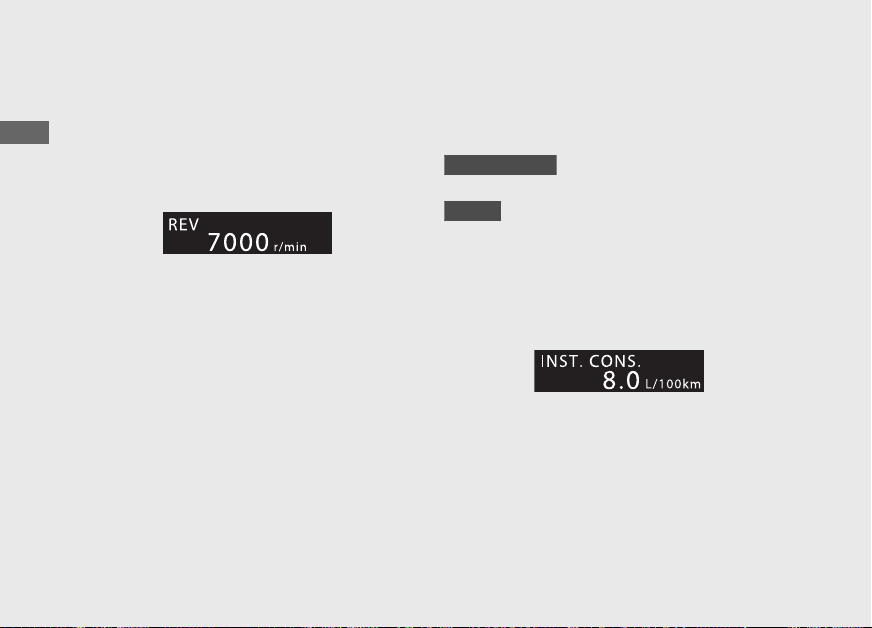
Numerical tachometer display [REV]
Displays engine revolutions per minutes.
Display range: 0 to 17,000 r/min (rpm)
Operation Guide
● Above 17,000 r/min (rpm): “17000” is
displayed.
32
Current fuel mileage [INST. CONS.]
Displays the current instant fuel mileage.
Display range:
GS, MA, U type
: 0.0 to 99.9 L/100km (km/L or
MPG or mile/L )
IN type
: 0.0 to 99.9 L/100km (km/L)
● When your speed is less than 7 km/h (4
mph): “--.-” is displayed.
● Above 99.9 L/100km: “--.-” is displayed.
● Above 99.9 km/L (MPG or mile/L): “99.9”
is displayed.
When “--.-” is displayed except for the
above-mentioned cases, go to your dealer
for service.
Page 37
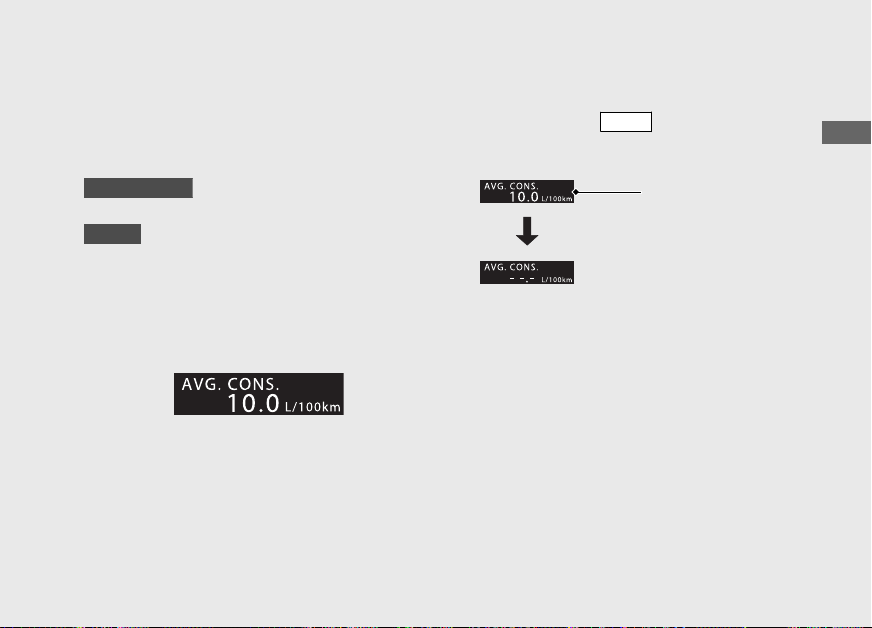
Average fuel mileage [AVG. CONS.]
Displays the average fuel mileage since the
average fuel mileage was reset.
Display range:
GS, MA U type
: 0.0 to 99.9 L/100km (km/L or
MPG or mile/L )
IN type
: 0.0 to 99.9 L/100km (km/L)
● Above 99.9 L/100km: “--.-” is displayed.
● Above 99.9 km/L (MPG or mile/L ): “99.9”
is displayed.
● When the average fuel mileage is reset:
“--.-” is displayed.
When “--.-” is displayed except for the
above-mentioned cases, go to your dealer
for service.
To Reset the Average Fuel Mileage
#
Press and hold the
MODE
button with the
average fuel mileage displayed.
Average fuel
mileage
Operation Guide
Continued
33
Page 38
Instruments (Continued)
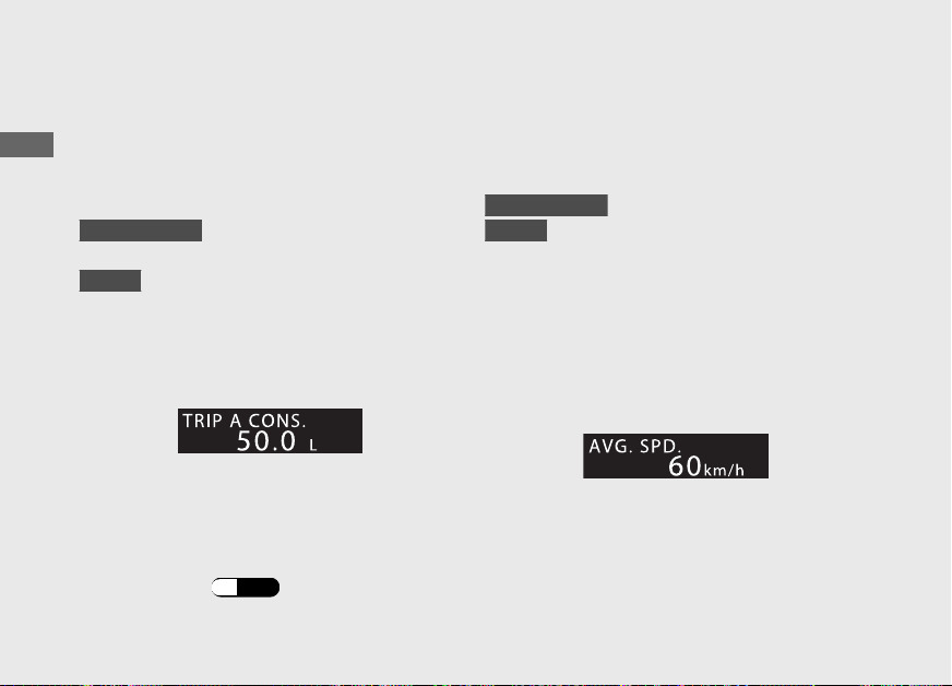
Tripmeter A fuel consumption [TRIP A
CONS.]
Displays the tripmeter A fuel consumption
Operation Guide
since the tripmeter A was reset.
Display range:
GS, MA, U type
300.0 GAL (gallon)
IN type
● Above 300 L (litres) or 300 GAL (gallon):
“300.0” is displayed.
● When the tripmeter A fuel consumption is
reset: “---.-” is displayed.
When “---.-” is displayed except for the
above-mentioned cases, go to your dealer
for service.
To reset the tripmeter A fuel
consumption: (P.29)
34
: 0.0 to 300.0 L (litres) or 0.0 to
: 0.0 to 300.0 L (litres)
Average speed [AVG. SPD.]
Displays average speed since the engine was
started.
Display range:
GS, MA, U type
IN type
● Initial display: “---” is displayed.
● When your vehicle has traveled less than
: 0 to 299 km/h (0 to 186 mph)
: 0 to 299 km/h
0.2 km (0.12 mile) since the engine was
started: “---” is displayed.
● When your vehicle operating time is less
than 16 seconds since the engine was
started: “---” is displayed.
When “---” is displayed except for the abovementioned cases, go to your dealer for
service.
Page 39
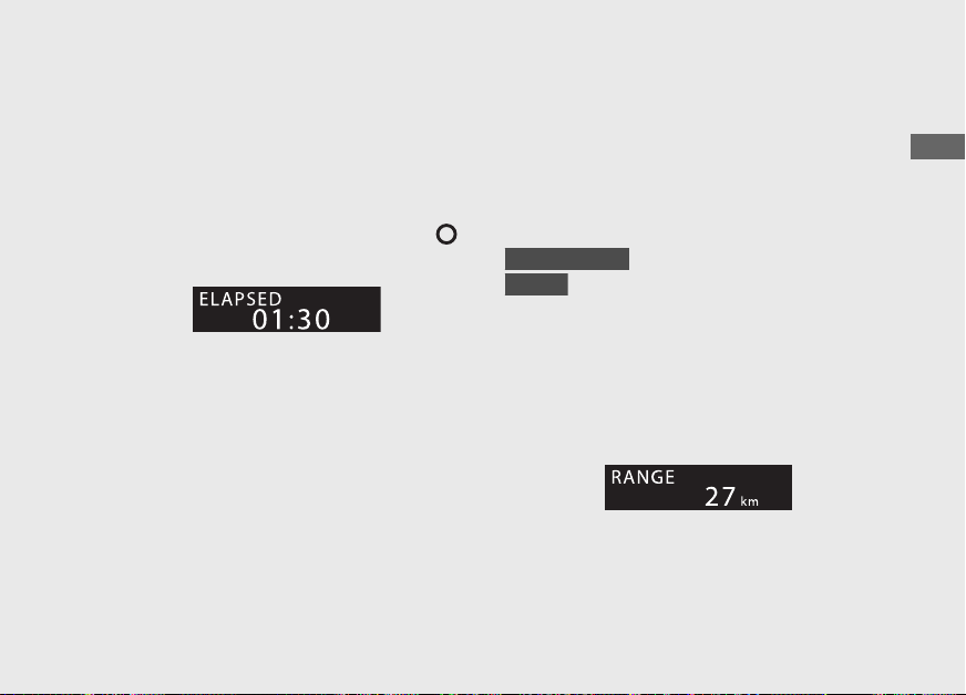
Elapsed time [ELAPSED]
Displays operating time since the engine was
started.
Display range: 00:00 to 99:59 (hours:minutes)
● Above 99:59: returns to 00:00.
When the ignition switch is turned to the
(Off) position, the elapsed time is reset.
When “--:--” is displayed, go to your dealer
for service.
Available riding distance [RANGE] (Only
reserve fuel mode)
When the low fuel indicator lights and the
low fuel pop-up information appears, the
estimated available riding distance is
indicated.
GS, MA, U type
IN type
● Above 99 km (mile): “99” is displayed.
● Below 1.0 L (0.2 GAL): “--” is displayed.
: 99 to 0 km (mile)
: 99 to 0 km
The indicated available riding distance is
calculated based on the riding states, and the
indicated figure may not always be the actual
allowable distance.
When “--” is displayed except for the abovementioned cases, go to your dealer for
service.
Operation Guide
Continued
35
Page 40
Instruments (Continued)
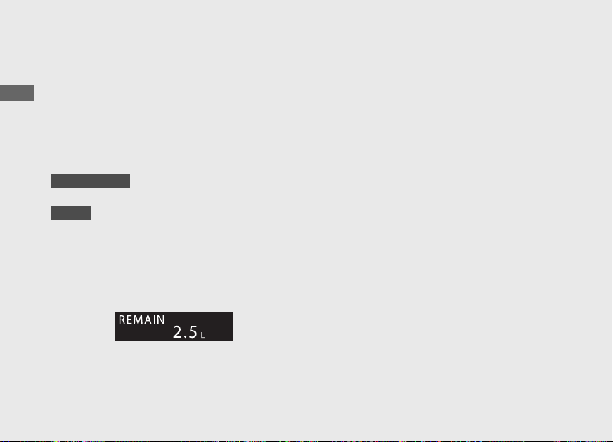
Amount of remaining fuel [REMAIN]
(Only reserve fuel mode)
When the low fuel indicator lights and the
Operation Guide
low fuel pop-up information appears, the
estimated amount of remaining fuel can be
selected.
Display range:
GS, MA, U type
0.2 GAL (gallon)
IN type
● Below 1.0 L (0.2 GAL): “-.-” is displayed.
The amount of remaining fuel is calculated
based on the riding states.
The indicated amount of remaining fuel may
be different from the actual amount.
36
: 4.0 to 1.0 L (litres) or 0.9 to
: 4.0 to 1.0 L (litres)
When “-.-” is displayed except for the abovementioned cases, go to your dealer for
service.
Page 41
Reserve Fuel Mode
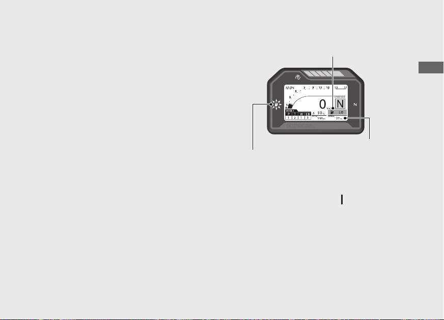
When the low fuel indicator lights and the
low fuel pop-up information appears, the
available riding distance is indicated, and the
amount of remaining fuel display can be
selected.
You should refill the tank as soon as possible.
Low fuel pop-up information
Operation Guide
Remaining fuel amount turned to the reserve
fuel mode:
4.0 L (1.1 US gal, 0.9 Imp gal)
Available riding
Low fuel indicator
distance
After refuelling more than the reserve
amount, the display returns to normal when
the ignition switch has been (On) position
for about a minute.
Continued
37
Page 42
Instruments (Continued)
INFO 3 display
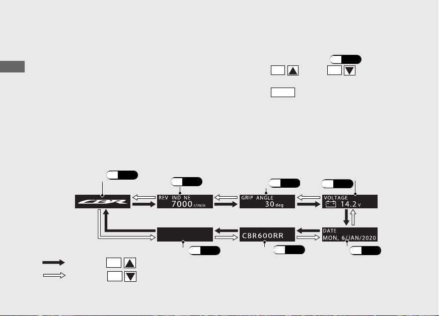
You can select the following:
Operation Guide
• CBR Logo
• Shift indicator set value [REV IND NE]
• Throttle grip angle [GRIP ANGLE]
• Battery voltage [VOLTAGE]
• Date [DATE]
• User letter
• Blank display
Changing the INFO 3 display
a
Select the INFO 3 display. (P.26)
b
Press the
SEL
(up) or
SEL
(down)
button until the desired display is displayed.
c
Press the
MODE
button. The INFO 3 display
is set, and then the display moves to the
riding mode display.
38
CBR Logo (P.39)
Press the
Press the
SEL
(up) button
SEL
(down) button
Shift indicator set
value (P.39)
Blank display (P.40)
Throttle grip
angle
(P.39)
User letter (P.40)
Battery voltage
(P.39)
Date (P.40)
Page 43
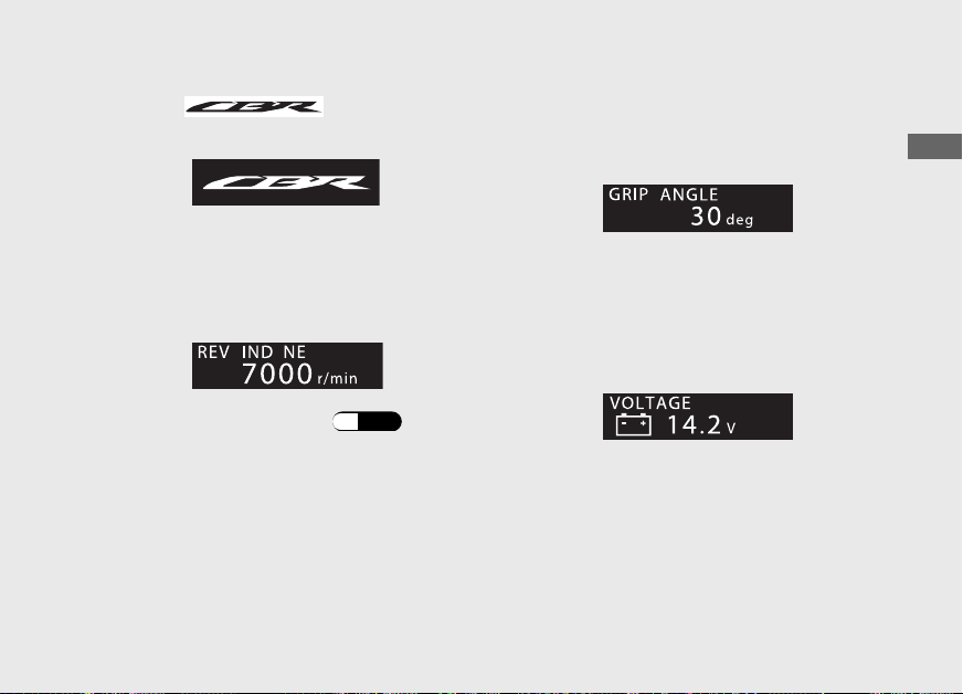
CBR logo
Displays the CBR logo.
Throttle grip angle [GRIP ANGLE]
Displays the throttle grip angle during
operation.
Operation Guide
Shift indicator set value [REV IND NE]
Displays the shift indicator set value.
Display range: OFF or 4,000 - 17,500 r/min
To set the shift indicator: (P.52
)
When “--” is displayed, go to your dealer for
service.
Battery voltage [VOLTAGE]
Displays the current voltage.
Continued
39
Page 44
Instruments (Continued)
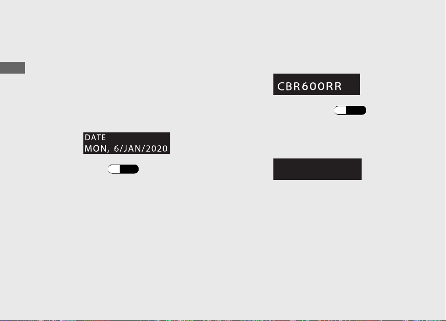
Date [DATE]
Displays the today's date.
Display range:
Operation Guide
Day of the week: MON to SUN
DAY: 1 to 31
Month: JAN to DEC
Year: 2010 to 2099
To set the Date: (P.61)
40
User letter
Displays the characters of user's choice.
To set the USER LETTER: (P.55
)
Blank display
Display the blank.
Page 45
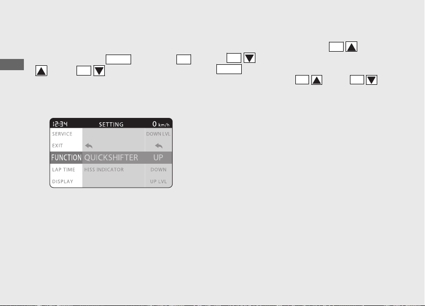
Setting mode
You can perform the following:
● FUNCTION (P.44)
u Quick Shifter
“UP”, “DOWN”, “UP LVL” and “DOWN
LVL” are displayed but not selectable.
u Setting the HISS
● LAP TIME (P.46)
u
Checking the lap time
u
Resetting the lap time
DISPLAY (P.49
●
)
u Changing the display mode
u Setting the shift indicator
u Setting the backlight brightness
u Setting the back ground
u Setting the user letter
u Setting the favorite
● GENERAL (P.60)
u Setting the date and clock
u Setting each meter unit
u Resetting to factory default settings
● SERVICE (P.68)
u Checking the next inspection schedule
u Quick Shifter
“INITIALIZE” and “EQUIPMENT” are
displayed but not selectable.
u Checking the current problem with the
PGM-FI system.
u “SPORTS KIT ECU USAGE” is displayed
but not usable.
Operation Guide
Continued
41
Page 46
Instruments (Continued)
To Shift to the Setting Mode
#
Press and hold the
Operation Guide
(up) or
menu screen is displayed with your vehicle
stopped.
Main menu screen
42
SEL
MODE
button and
(down) button until main
SEL
Select a menu by pressing the
SEL
or
(down) button and press the
MODE
button.
u Press and hold the
(down) button to move the menu quickly.
SEL
SEL
(up) or
(up)
SEL
Page 47
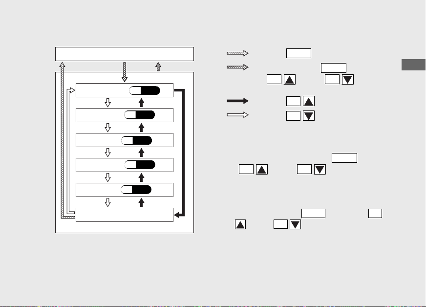
Ordinary display
FUNCTION (P.44)
LAP TIME (P.46)
Press the
MODE
button
Press and hold the
SEL
and
(up) or
button
Press the
Press the
SEL
(up) button
SEL
(down) button
MODE
SEL
(down)
button
Operation Guide
DISPLAY (P.49)
GENERAL (P.60)
SERVICE (P.68)
EXIT
To end the setting
Select the “EXIT” menu on the main menu
screen, or press and hold the
and
SEL
(up) or
SEL
MODE
button
(down) button.
Also, the setting mode is ended when your
vehicle speed reaches approximately 1 km/h
(1 mph).
u Press and hold the
(up) or
SEL
(down) button to return
MODE
button and
SEL
to the ordinary display.
Note that doing so cancels the settings left
incomplete.
Continued
43
Page 48
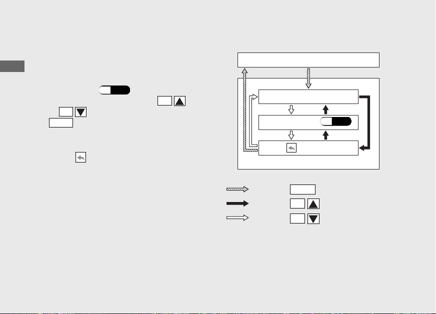
Instruments (Continued)
FUNCTION
To Set the FUNCTION Menu
#
Operation Guide
a
Select the “FUNCTION” menu on the main
menu screen. (P.42)
b
Select a menu by pressing the
SEL
or
(down) button and press the
MODE
button.
SEL
(up)
"FUNCTION" is selected
FUNCTION
QUICK SHIFTER
HISS INDICATOR (P.45)
To end the setting
Select the (return) on the menu screen.
The display returns to the “FUNCTION” menu
on the main menu screen.
44
Press the
Press the
Press the
(return)
MODE
button
SEL
(up) button
SEL
(down) button
Page 49
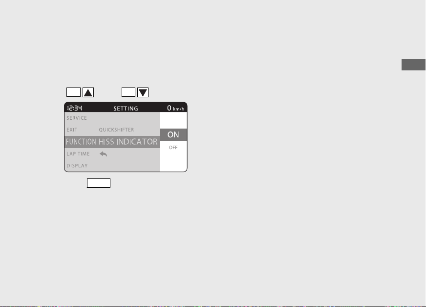
HISS INDICATOR
#
You can select the blinking or turning off the
HISS indicator.
a
Select the “ON” (blinks) or “OFF” (off) using
the
SEL
(up) or
SEL
(down) button.
Operation Guide
b
Press the
MODE
button. The HISS indicator
setting is set, and then the display returns to
the upper level hierarchy.
Continued
45
Page 50
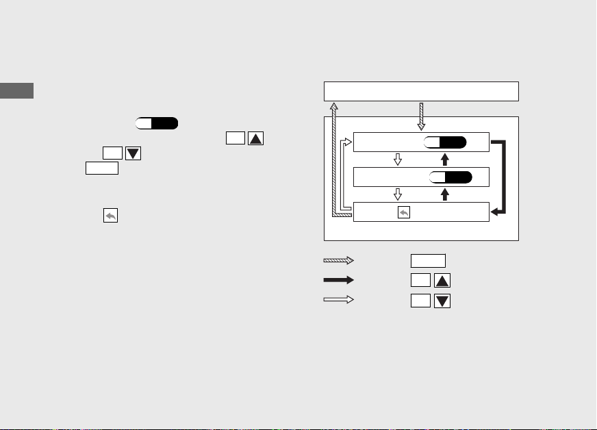
Instruments (Continued)
LAP TIME
"LAP TIME" is selected
To Set the LAP TIME Menu
#
Operation Guide
a
Select the “LAP TIME” menu on the main
menu screen. (P.42)
b
Select the menu by pressing the
SEL
(up) or
the
(down) button, and press
MODE
button.
To end the setting
Select the (return) on the menu screen.
The display returns to the “LAP TIME” menu
on the main menu screen.
46
SEL
LAP TIME
LAP DATA (P.47)
CLEAR DATA (P.48)
(return)
Press the
Press the
Press the
MODE
SEL
(up) button
SEL
(down) button
button
Page 51
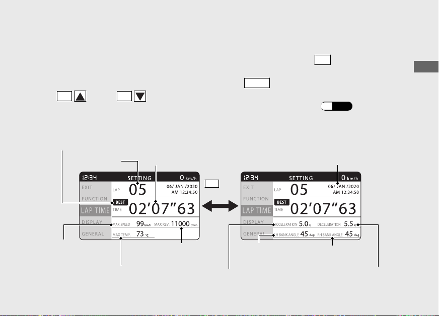
LAP DATA
#
The history of recorded lap time and
information are displayed.
To display the other lap information, press
the
SEL
(up) or
SEL
(down) button.
To display the maximum acceleration,
angle and maximum right bank angle
information, press the
To end the display of lap time history, press
MODE
the
button. The display returns to the
upper level hierarchy.
To use the Lap Timer
maximum deceleration, maximum left bank
Best icon (Appears when the fastest lap time displayed.)
Lap number
Lap time
Press the
LAP
button
LAP
button.
(P.74)
Time stamp
Operation Guide
Maximum
vehicle speed
Maximum engine
revolutions
Maximum coolant temperature
Maximum left
bank angle
Maximum acceleration
Maximum right
bank angle
Maximum deceleration
Continued
47
Page 52
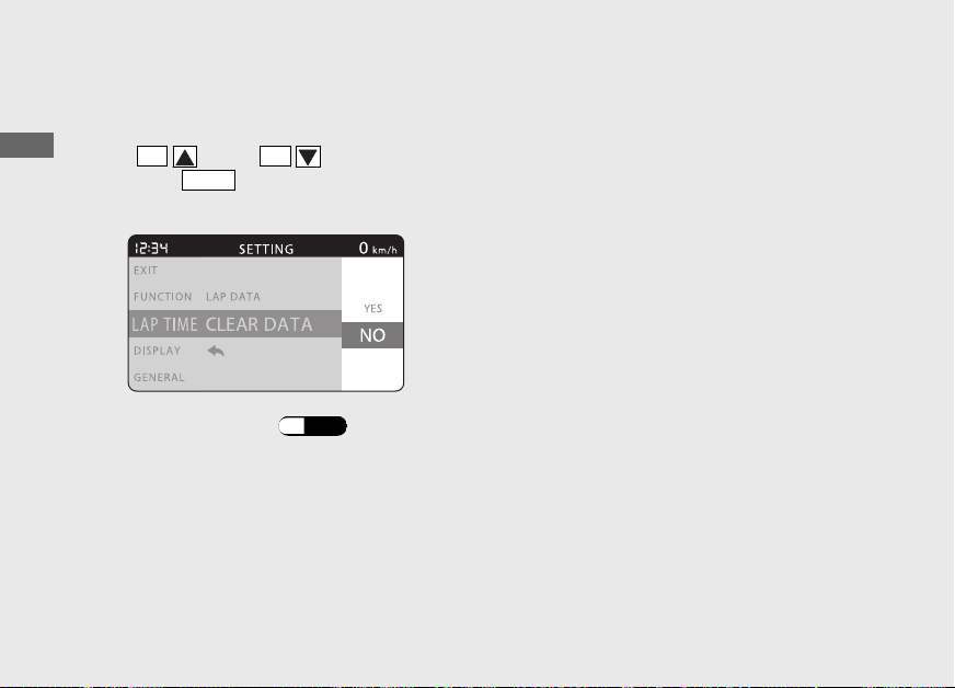
Instruments (Continued)
CLEAR DATA
#
a
Select “NO” (not clear) or “YES” (clear) using
SEL
the
Operation Guide
b
To use the Lap Timer (P.74)
48
(up) or
Press the
to the upper level hierarchy.
MODE
button. The display returns
SEL
(down) button.
Page 53
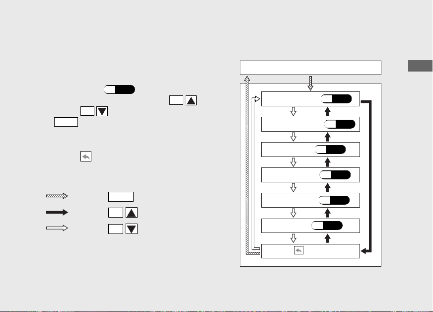
DISPLAY
"DISPLAY" is selected
To Set the DISPLAY Menu
#
a
Select the “DISPLAY” menu on the main
menu screen. (P.42)
b
Select the menu by pressing the
SEL
(up) or
MODE
(down) button and press the
button.
SEL
To end the setting
Select the (return) on the menu screen.
The display returns to the “DISPLAY” menu
on the main menu screen.
Press the
Press the
Press the
MODE
button
SEL
(up) button
SEL
(down) button
DISPLAY
DISPLAY MODE (P.50)
SHIFT INDICATOR (P.52)
BRIGHTNESS (P.53)
BACKGROUND (P.54)
USER LETTER (P.55)
FAVORITE (P.56)
(return)
Continued
Operation Guide
49
Page 54
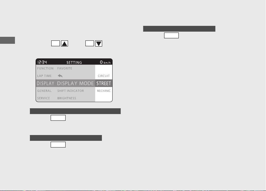
Instruments (Continued)
DISPLAY MODE
#
a
Select “STREET”, “MECHANIC” or “CIRCUIT”
Operation Guide
using the
button.
When the “STREET” or “CIRCUIT” is selected
b
Press the
setting is set, and then the display returns to
the upper level hierarchy.
When the “MECHANIC” is selected
Press the
to the mechanic mode.
50
SEL
(up) or
MODE
MODE
SEL
(down)
button. The display mode
button. The display moves
When the “MECHANIC” is selected
c
Press the
MODE
button. The mechanic
mode ends, and then the display returns to
the upper level hierarchy.
u The display mode returns to the
previously selected mode.
Page 55
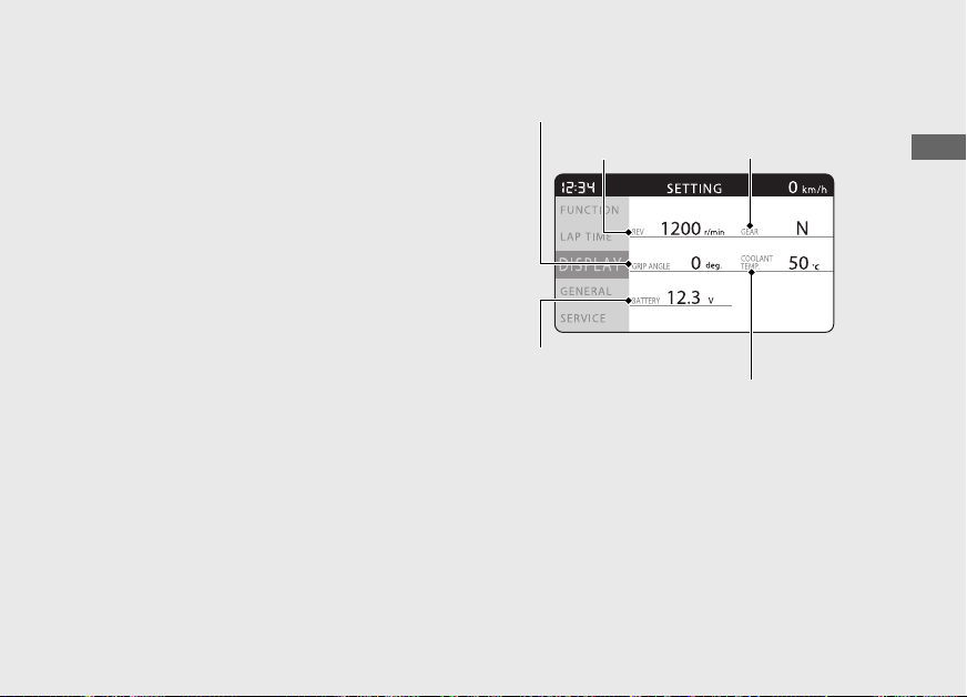
Mechanic Mode
Displays the current information of the
vehicle.
Displays the following information:
● Tachometer
● Gear position
● Throttle grip position
● Coolant temperature
● Battery voltage
Throttle grip position
Tachometer Gear position
Battery voltage
Coolant temperature
Operation Guide
Continued
51
Page 56
Instruments (Continued)
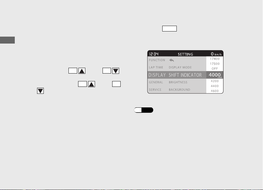
SHIFT INDICATOR
#
You can change the setting of the shift
Operation Guide
indicators.
a
Select the “OFF” (deactivate) or an engine
revolution at which the shift indicators start
blinking using the
(down) button.
u Press and hold the
quickly.
The value increases by 200 r/min (rpm)
u
increments.
Available setting range:
u
4,000 - 17,500 r/min (rpm)
52
(down) button to move the menu
SEL
(up) or
SEL
SEL
(up) or
b
Press the
MODE
button. The shift indicator
setting is set, and then the display returns to
the upper level hierarchy.
SEL
Information of the Shift Indicator:
(P.83
)
Page 57
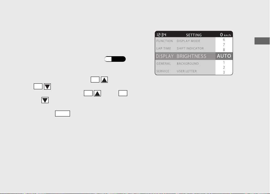
BRIGHTNESS
#
You can adjust the backlight brightness to
one of the eight levels or select the auto
adjustment.
Automatic brightness control (P.160)
a
Select the “AUTO” (auto adjustment) or
brightness level using the
SEL
(down) button.
u
Press and hold the
SEL
SEL
(up) or
(up) or
SEL
(down) button to move the menu
quickly.
b
Press the
MODE
button. The backlight
brightness setting is set, and then the display
returns to the upper level hierarchy.
Operation Guide
Continued
53
Page 58
Instruments (Continued)
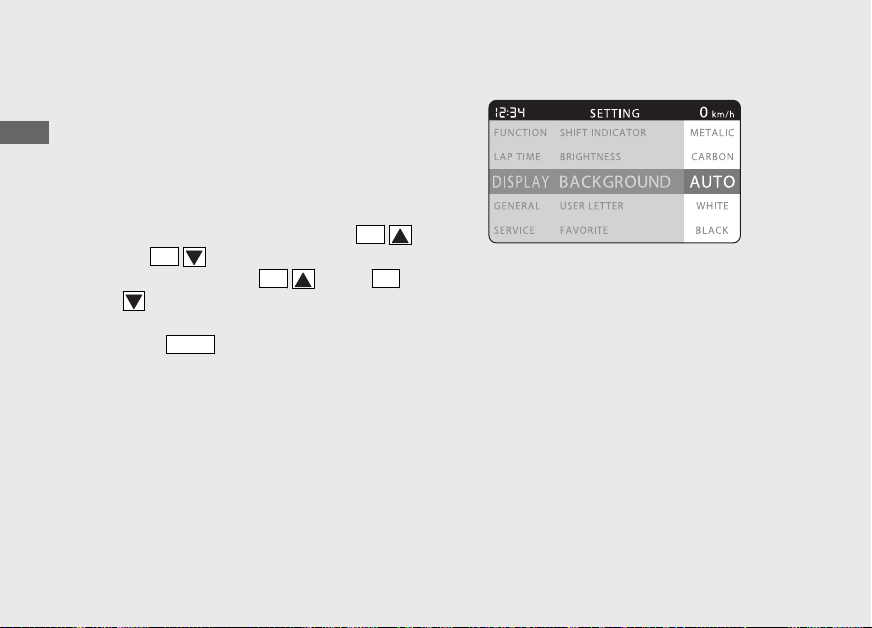
BACKGROUND
#
You can change the setting of the
Operation Guide
background to one of the four categories or
select the auto adjustment.
a
Select the “AUTO”, “WHITE”, “BLACK”,
“METALLIC” or “CARBON” using the
SEL
(up) or
u Press and hold the
b
Press the
setting is set, and then the display returns to
the upper level hierarchy.
54
(down) button.
SEL
(up) or
(down) button to move the menu
quickly.
MODE
button. The background
SEL
SEL
Page 59
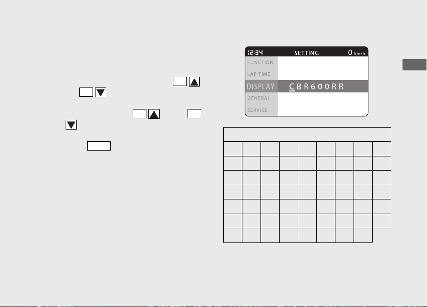
USER LETTER
#
You can select any 10 characters you like.
a
Select the first character using the
SEL
(up) or
(down) button until a
SEL
desired character appears
u Press and hold the
SEL
(up) or
(down) button to move the menu
quickly.
b
Press the
MODE
button. The cursor moves
to the next position.
c
Repeat the steps a and b to select
characters for the other positions until a
desired word is complete.
d
When the tenth character is selected, the
display returns to the upper level hierarchy.
Operation Guide
SEL
A list of characters that can be selected
A B C D E F G H I
J K L M N O P Q R
S T U V W X Y Z 0
1 2 3 4 5 6 7 8 9
! ” # $ % & ‘ ’ (
) * + , - . / : ;
< > = ? @ ^ _
Continued
55
Page 60
Instruments (Continued)
FAVORITE
#
You can change the indications on the INFO
Operation Guide
1, INFO 2, and INFO 3 to the following
information by pressing the
the street mode is displayed.
INFO 1:
“TOTAL”, “TRIP A” or “TRIP B”
INFO 2:
“REV”, “INST.CONS.”, “AVG.CONS.”, “TRIP A
CONS.”, “AVG.SPD.” or “ELAPSED”
INFO 3:
“CBR LOGO”, “REV IND NE”, “GRIP ANGLE”,
“VOLTAGE”, “DATE”, “USER LETTER” or a
blank display
56
LAP
button while
To end the setting
Select the (return) on the menu screen.
The display returns to the “FAVORITE” menu
on the “DISPLAY” menu screen.
Page 61
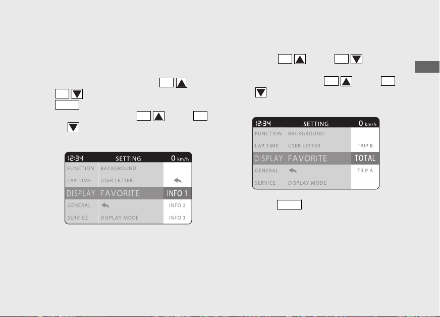
INFO 1
You can select the “TOTAL”, “TRIP A” or “TRIP
B” for INFO 1.
a
Select the “INFO 1” using the
SEL
(down) button, and press the
MODE
button.
u Press and hold the
SEL
SEL
(up) or
(up) or
SEL
(down) button to move the menu
quickly.
b
Select the “TOTAL”, “TRIP A” or “TRIP B”
using the
SEL
(up) or
SEL
(down)
button.
u Press and hold the
SEL
(up) or
(down) button to move the menu
quickly.
SEL
Operation Guide
c
Press the
MODE
button. The “INFO 1”
setting is set, and then the display returns to
the upper level hierarchy.
Continued
57
Page 62
Instruments (Continued)
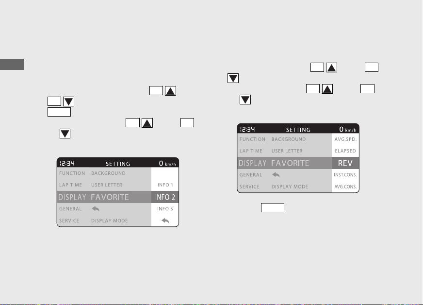
INFO 2
You can select the “REV”, “INST.CONS.”,
“AVG.CONS.”, “TRIP A CONS.”, “AVG.SPD.” or
Operation Guide
“ELAPSED” for INFO 2.
SEL
(up) or
SEL
a
Select the “INFO 2” using the
SEL
(down) button, and press the
MODE
button.
u
Press and hold the
(down) button to move the menu
quickly.
(up) or
SEL
b
Select the “REV”, “INST.CONS.”,
“AVG.CONS.”, “TRIP A CONS.”, “AVG.SPD.”
or “ELAPSED” using the
SEL
(up) or
(down) button.
u Press and hold the
SEL
(up) or
(down) button to move the menu
quickly.
SEL
SEL
58
c
Press the
MODE
button. The “INFO 2”
setting is set, and then the display returns to
the upper level hierarchy.
Page 63
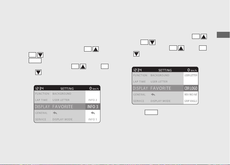
INFO 3
You can select the “CBR LOGO”, “REV IND
NE”, “GRIP ANGLE”, “VOLTAGE”, “DATE”,
“USER LETTER” or blank display for INFO 3.
SEL
(up) or
SEL
(up) or
SEL
a
Select the “INFO 3” using the
SEL
(down) button, and press the
MODE
button.
u
Press and hold the
(down) button to move the menu
quickly.
b
Select the “CBR LOGO”, “REV IND NE”, “GRIP
ANGLE”, “VOLTAGE”, “DATE”, “USER
LETTER” or blank display using the
SEL
(up) or
u Press and hold the
(down) button.
SEL
SEL
(up) or
(down) button to move the menu
quickly.
SEL
Operation Guide
c
Press the
MODE
button. The “INFO 3”
setting is set, and then the display returns to
the upper level hierarchy.
Continued
59
Page 64
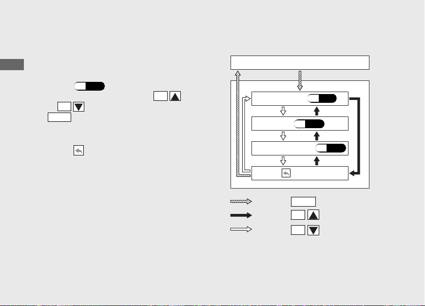
Instruments (Continued)
GENERAL
To Set the GENERAL Menu
#
Operation Guide
a
Select the “GENERAL” on the main menu
screen. (P.42)
b
Select a menu by pressing the
SEL
or
(down) button and press the
MODE
button.
To end the setting
Select the
(return) menu on the menu
screen. The display returns to the “GENERAL”
on the main menu screen.
SEL
(up)
"GENERAL" is selected
GENERAL
DATE & TIME (P.61)
UNITS (P.62)
RESTORE DEFAULT (P.66)
(return)
60
Press the
Press the
Press the
MODE
button
SEL
(up) button
SEL
(down) button
Page 65
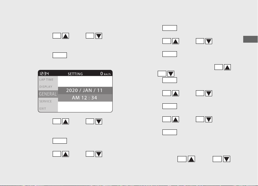
DATE & TIME
#
a
Press the
SEL
(up) or
SEL
(down)
button until the desired tens digit of the year
is displayed.
b
Press the
MODE
button. The cursor moves
to the ones digit of the year.
c
Press the
SEL
(up) or
SEL
(down)
button until the desired ones digit of the
year is displayed.
d
Press the
MODE
button. The cursor moves
to the indication of month.
e
Press the
SEL
(up) or
SEL
(down)
button until the desired month is displayed.
f
Press the
MODE
button. The cursor moves
to the indication of date.
g
Press the
SEL
(up) or
SEL
(down)
button until the desired date is displayed.
h
Press the
MODE
button. The cursor moves
to the “AM” or “PM”.
i
Select the “AM” or “PM” using the
SEL
(up) or
j
Press the
(down) button.
MODE
button. The cursor moves
SEL
to the indication of hour.
k
Press the
SEL
(up) or
SEL
(down)
button until the desired hour is displayed.
l
Press the
MODE
button. The cursor moves
to the indication of minute.
m
Press the
SEL
(up) or
SEL
(down)
button until the desired minute is displayed.
n
Press the
MODE
button. The date and clock
setting is set, and then the display returns to
the upper level hierarchy.
Press and hold the
SEL
(up) or
SEL
(down) button to move the menu quickly.
Continued
Operation Guide
61
Page 66
Instruments (Continued)
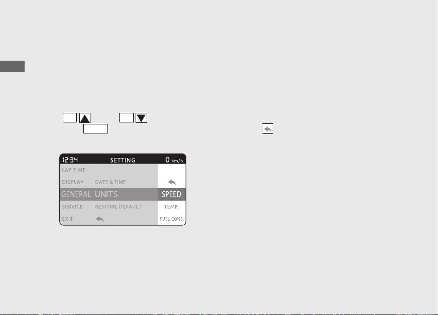
UNITS
#
You can change the speed and mileage, and
Operation Guide
fuel mileage meter units.
To set each unit
a
Select the “SPEED” or “FUEL CONS.” using
SEL
the
(up) or
b
Press the
to each unit setting screen.
MODE
The units of the speedometer, odometer,
tripmeter A/B, current fuel mileage, average
fuel mileage, tripmeter A fuel consumption,
average speed, available driving distance and
62
SEL
(down) button.
button. The display moves
amount of remaining fuel are changed in
“SPEED” menu.
The units of the current fuel mileage, average
fuel mileage and amount of remaining fuel
are changed in “FUEL CONS.” menu.
To end the setting
Select the
(return) on the menu screen.
The display returns to the “UNITS” menu on
the “GENERAL” menu screen.
Page 67
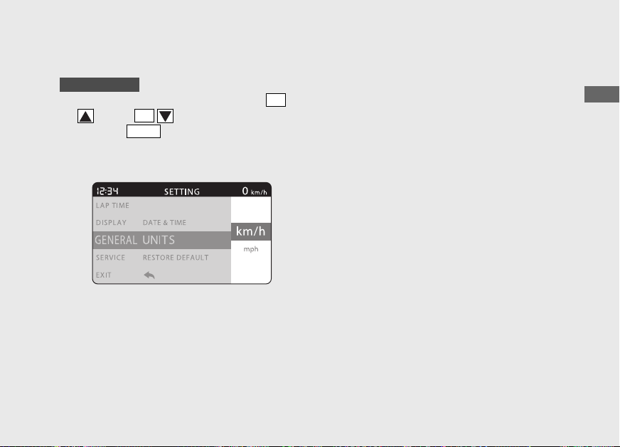
Speed and Mileage Unit [SPEED]
GS, MA, U type
a
Select the “km/h” or “mph” using the
SEL
b
Press the
(up) or
(down) button.
MODE
button. The speed and
SEL
mileage unit setting is set, and then the
display returns to the upper level hierarchy.
When selecting the “km/h”
● Units of the speedometer and average
speed show “km/h”.
● Units of the odometer, tripmeter A/B and
available driving distance show “km”.
● Units of the current fuel mileage and
average fuel mileage show “L/100km” or
“km/L”.
● Units of the tripmeter A fuel consumption
and amount of remaining fuel show “L”.
When selecting the “mph”
● Units of the speedometer and average
speed show “mph”.
● Units of the odometer, tripmeter A/B and
available driving distance show “mile”.
● Units of the current fuel mileage and
average fuel mileage show “MPG” or
“mile/L”.
● Units of the tripmeter A fuel consumption
and amount of remaining fuel show “L” or
“GAL”.
Operation Guide
Continued
63
Page 68
Instruments (Continued)
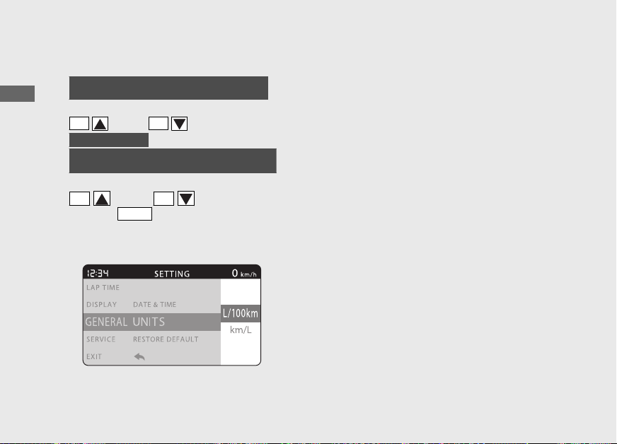
Fuel Mileage Meter Unit [FUEL CONS.]
When the “km/h” of the “SPEED” menu is
a
Operation Guide
selected
Select the “L/100 km” or “km/L” using the
SEL
(up) or
GS, MA, U type
When the “mph” of the “SPEED” menu is
selected
SEL
(down) button.
Select the “MPG” or “mile/L” using the
SEL
b
Press the
(up) or
SEL
(down) button.
MODE
button. The fuel mileage
meter unit setting is set, and then the display
returns to the upper level hierarchy.
64
When selecting the “L/100 km”
● Units of the current fuel mileage and
average fuel mileage show “L/100 km”.
● Units of the tripmeter A fuel consumption
and amount of remaining fuel show “L”.
When selecting the “km/L”
● Units of the current fuel mileage and
average fuel mileage show “km/L”.
● Units of the tripmeter A fuel consumption
and amount of remaining fuel show “L”.
When selecting the “MPG”
● Units of the current fuel mileage and
average fuel mileage show “MPG”.
● Units of the tripmeter A fuel consumption
and amount of remaining fuel show
“GAL”.
Page 69
When selecting the “mile/L”
● Units of the current fuel mileage and
average fuel mileage show “mile/L”.
● Units of the tripmeter A fuel consumption
and amount of remaining fuel show “L”.
Operation Guide
Continued
65
Page 70
Instruments (Continued)
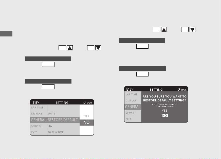
RESTORE DEFAULT
#
The set value can be returned to default
Operation Guide
setting.
a
Select the “NO” (not restore) or “YES”
(restore) using the
(down) button.
When the “NO” is selected
b
Press the
MODE
maintained, and then the display returns to
the upper level hierarchy.
When the “YES” is selected
Press the
MODE
changes to the confirmation screen.
66
SEL
(up) or
button. The set value is
button. The display
SEL
c
Select the “NO” (not restore) or “YES”
(restore) using the
SEL
(up) or
SEL
(down) button on the confirmation screen.
When the “NO” is selected
d
Press the
maintained, and then the display returns to
MODE
button. The set value is
the “RESTORE DEFAULT” menu on the
“GENERAL” menu screen.
When the “YES” is selected
Press the
MODE
button. The set value
return to default setting.
Page 71
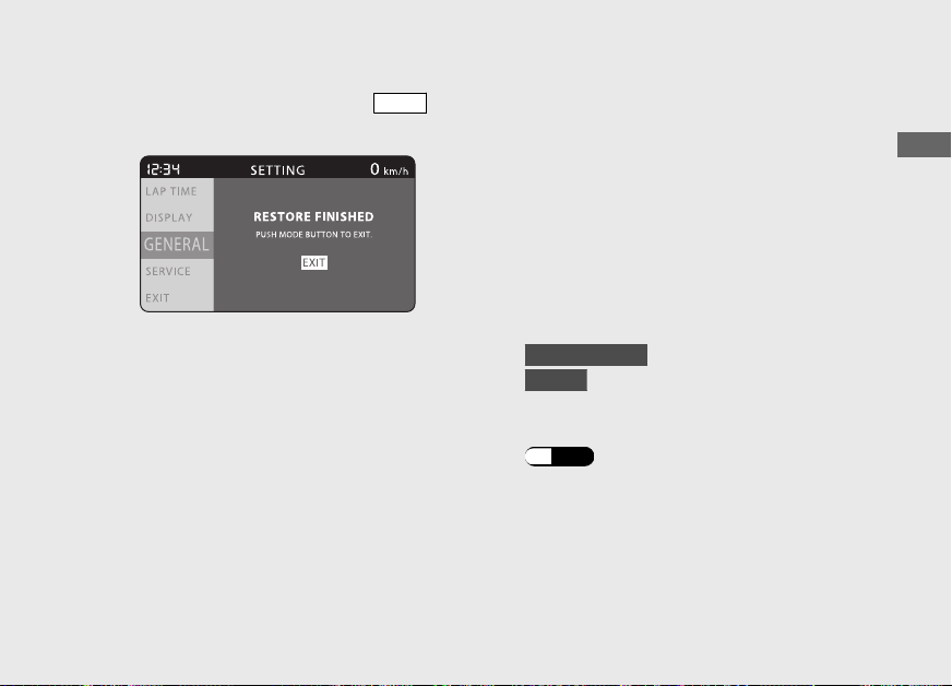
e
Select the “EXIT” by pressing the
button.
f
The display returns to the “RESTORE
DEFAULT” menu on the “GENERAL” menu
screen.
MODE
Default setting values:
● LAP DATA: Cleared
● DISPLAY MODE: STREET
● SHIFT INDICATOR: OFF
● BRIGHTNESS: AUTO
● BACK GROUND: AUTO
● USER LETTER: CBR600RR
● FAVORITE: TOTAL, REV, CBR LOGO
● SPEED UNIT: km/h
● FUEL CONS UNIT:
GS, MA, U type
IN type
● Riding mode: USER 1 and USER 2 setting
L/100 km
km/L
value returns to initial setting values.
(P.88)
● HISS INDICATOR: ON
Operation Guide
Continued
67
Page 72
Instruments (Continued)
SERVICE
To Set the SERVICE Menu
#
Operation Guide
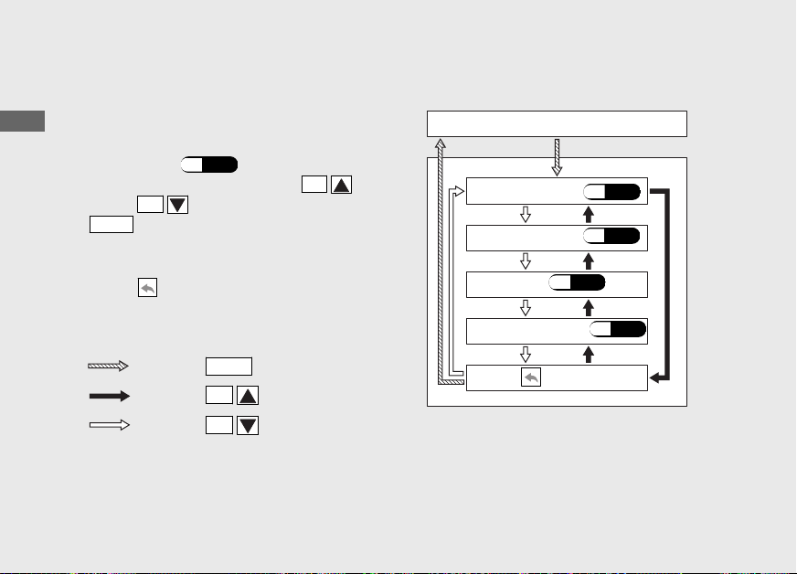
a
Select the “SERVICE” menu on the main
menu screen. (P.42)
b
Select the menu by pressing the
SEL
(up) or
MODE
To end the setting
Select the (return) on the menu screen,
and then the display returns to the “SERVICE”
menu on the main menu screen.
(down) button and press the
button.
SEL
"SERVICE" is selected
SERVICE
MAINTENANCE (P.69)
QUICK SHIFTER (P.72)
DTC (P.73)
SPORTS KIT ECU (P.73)
68
Press the
Press the
Press the
MODE
button
SEL
(up) button
SEL
(down) button
(return)
Page 73
MAINTENANCE
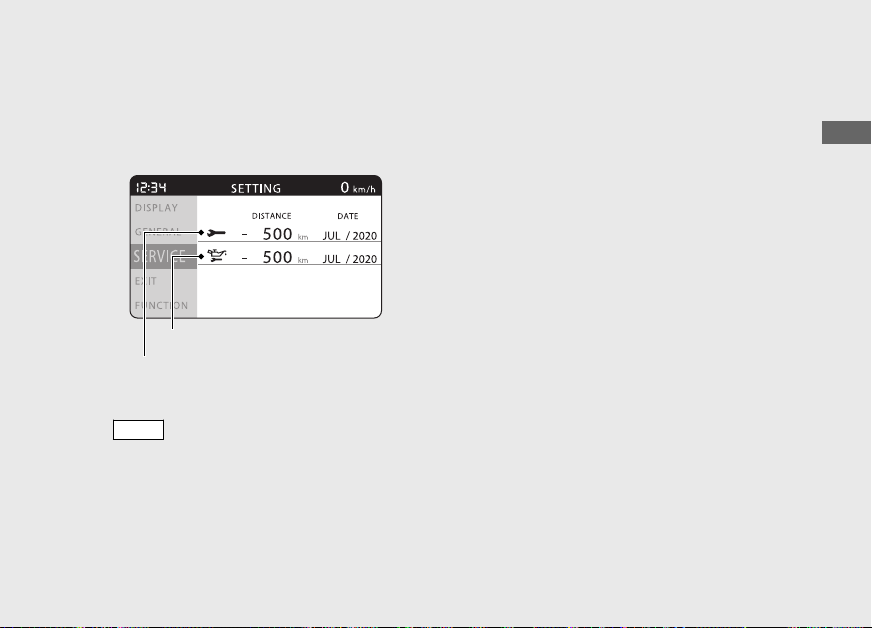
#
You can check the next inspection time and
change the setting of next inspection.
Next engine oil change
Next periodic inspection
To return to the upper level hierarchy, press
MODE
the
button.
Display range:
DISTANCE:
Next periodic inspection:
-12000 to +99900 km
(-8000 to +99950 mile)
Next engine oil change:
-6000 to +99980 km
(-4000 to +99980 mile)
u
Pass 0 km (mile): “-” mark changed to
“+” mark
DATE:
Month: JAN to DEC
Year: 2010 to 2099
Operation Guide
Continued
69
Page 74
Instruments (Continued)
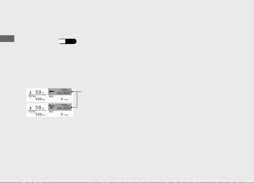
When reaching any of the following, the
pop-up information is appears in the
ordinary display. (P.78)
Operation Guide
● “-500 km”or “-300 mile” from the next
periodic inspection
● “-100 km” or “-60 mile” from the next
engine oil change
● One month before the set month
Maintenance
pop-up
information
70
Page 75
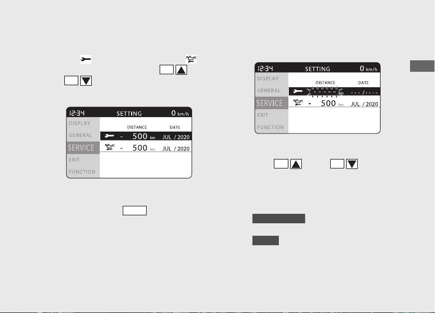
Next inspection setting
a
Select “ ” (periodic inspection ) or “ ”
(engine oil change) using the
SEL
or
(down) button.
SEL
(up)
Operation Guide
b
Press and hold the
MODE
“DISTANCE” value start flashing.
button until the
c
Press the
SEL
(up) or
SEL
(down)
button until the desired distance value is
displayed.
u Available setting range of periodic
inspection:
GS, MA, U type
: 100 to 12,000 km (100 to
8,000 mile)
IN type
: 100 to 6,000 km
u Available setting range of engine oil
change:
100 to 12,000 km (100 to 8,000 mile)
Continued
71
Page 76
Instruments (Continued)
d
Press the
to the indication of month.
e
Operation Guide
Press the
button until the desired month is displayed.
f
Press the
to the tens digit of the year.
g
Press the
button until the desired tens digit of the year
is displayed.
h
Press the
to the ones digit of the year.
i
Press the
button until the desired ones digit of the
year is displayed.
j
Press the
date setting is set, and then the display
returns to the upper level hierarchy.
72
MODE
SEL
(up) or
MODE
SEL
(up) or
MODE
SEL
(up) or
MODE
button. The cursor moves
SEL
(down)
button. The cursor moves
SEL
(down)
button. The cursor moves
SEL
(down)
button. The mileage and
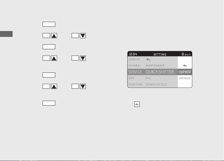
QUICK SHIFTER
#
“INITIALIZE” and “EQUIPMENT” are displayed
but not selectable.
Select the (return) on the menu screen,
and then the display returns to the
“QUICKSHIFTER” menu on the “SERVICE”
menu screen.
Page 77
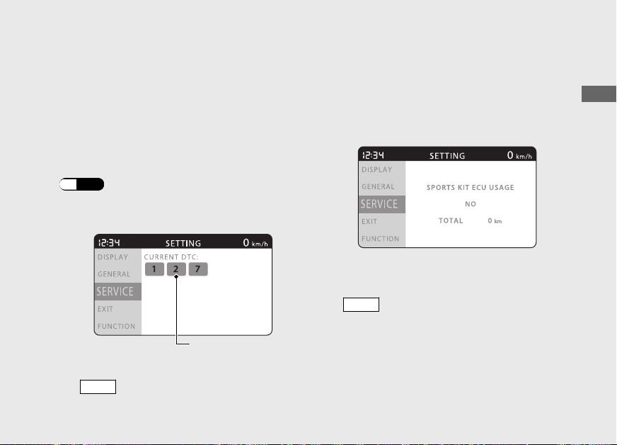
DTC
#
You can check for a current problem with the
PGM-FI system.
If your vehicle has problem, DTC index is
displayed. In this case, the pop-up
information appears in the ordinary display.
(P.78
)
Reduce speed and have your vehicle
inspected by your dealer as soon as possible.
DTC indexes
To return to the upper level hierarchy, press
MODE
the
button.
SPORTS KIT ECU
#
“SPORTS KIT ECU USAGE” is displayed but
not usable.
To return to the upper level hierarchy, press
MODE
the
button.
Operation Guide
Continued
73
Page 78
Instruments (Continued)
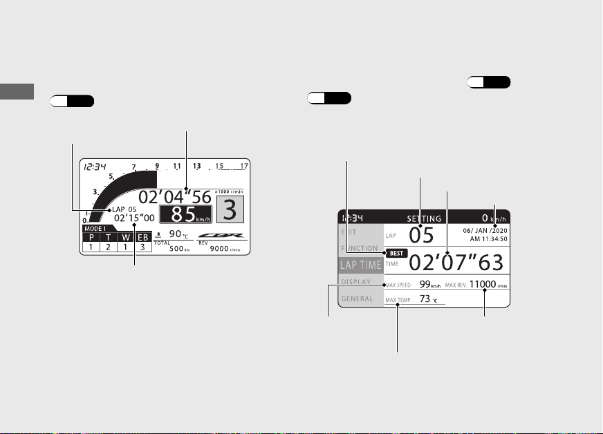
Lap Timer
You can record lap time in the circuit mode.
Operation Guide
(P.23)
Previous lap time
Previous lap number
Stopwatch/
difference with the best lap
You can check and clear the recorded lap
time data in the setting mode. (P.46)
(P.47)
Best icon
(Displayed when the fastest lap
time displayed.)
Lap number
Lap time
Time stamp
74
Maximum
vehicle
speed
Maximum engine
revolutions
Maximum coolant
temperature
Page 79
The lap time data include lap time, maximum
vehicle speed, maximum engine revolutions,
maximum coolant temperature, maximum
acceleration, maximum deceleration,
maximum left bank angle and maximum right
bank angle.
Display range:
Previous lap number: 0 to 50
u
Exceeds 50, repeats the “50”
Maximum vehicle speed:
0 to 299 km/h (0 to 186 mph)
Operation Guide
Maximum engine revolutions:
0 to 20000 r/min (rpm)
Maximum coolant temperature:
-40 to 150°C
Maximum acceleration: 0 to 8.0 G
Previous lap time: 00'00"00 to 99'59"99
u Exceeds 99'59"99, returns to the
“00'00"00”
Stopwatch: 00'00"00 to 99'59"99
u Exceeds 99'59"99, returns to the
“00'00"00”
Difference with the best lap:
-99'59"99 to 00'00"00 to +99'59"99
Maximum deceleration: 0 to 4.1 G
Maximum left bank angle:
0 to 90 deg
Maximum right bank angle:
0 to 90 deg
Continued
75
Page 80
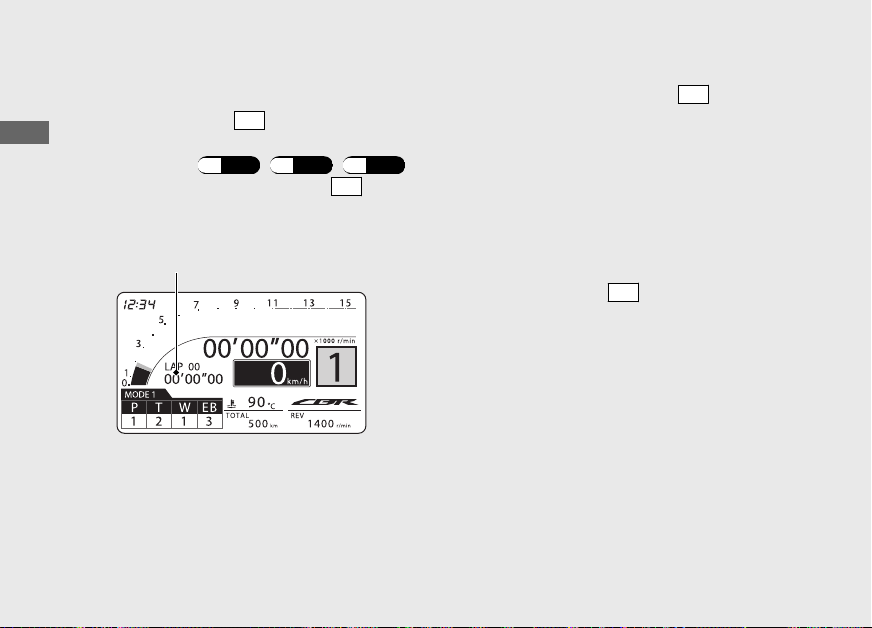
Instruments (Continued)
To Measure the Lap Time
#
a
Press and hold the
Operation Guide
“CIRCUIT” menu on the “DISPLAY MODE”
menu screen. (P.23) (P.49) (P.50
b
To start measurement, press the
button.
u The stopwatch starts measurement.
Stopwatch
76
LAP
button or select the
LAP
c
To record lap time, press the
LAP
button at
each lap.
u The stopwatch changes to display of the
)
difference with the best lap.
After 10 seconds, the display will return
to the stopwatch.
u
The previous lap time and previous lap
number change to the information of the
previous lap.
u
If you press the
LAP
button again within
two seconds, lap time is not recorded.
u
When exceeds 50 lap, the previous lap
number repeats the “LAP 50”.
Page 81
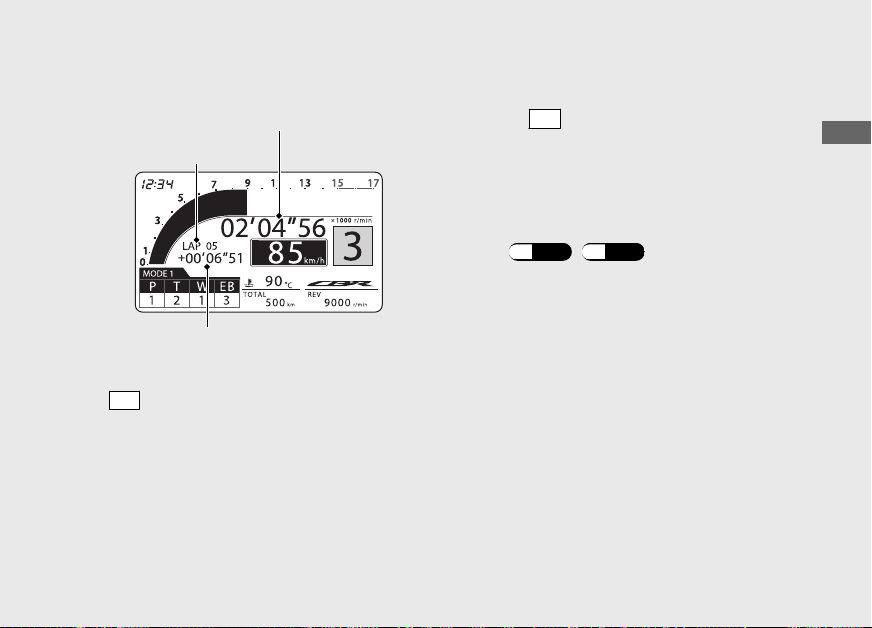
Previous lap time
Previous lap number
Difference with the best lap
d
To end measurement, press and hold the
LAP
button.
To restart the measurement
Press the
LAP
button again. The stopwatch
restarts measurement.
u Measurement starts from the next lap.
To Check or Clear the Lap Time
#
Select the “LAP TIME” menu in the setting
mode. (P.46) (P.48)
Operation Guide
Continued
77
Page 82
Instruments (Continued)
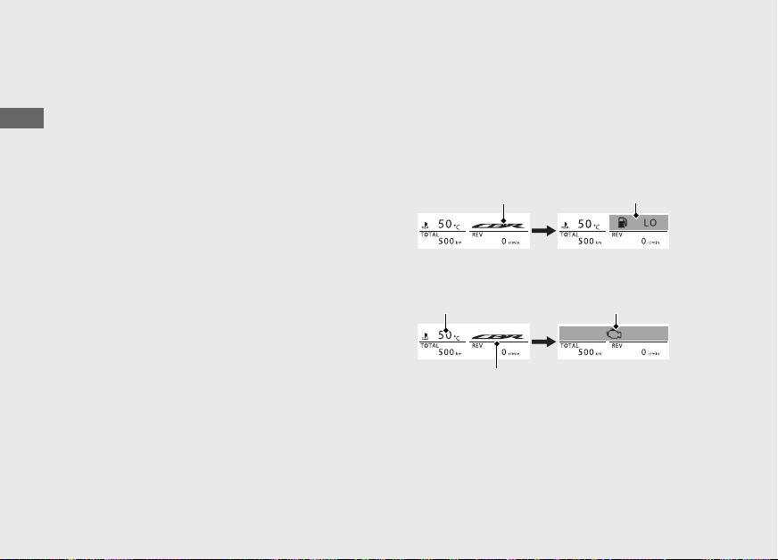
Pop-up information
In the following case, the INFO 3 display or
Operation Guide
the INFO 3 display and coolant temperature
gauge change to a pop-up information
display.
Maintenance information:
●
When the inspection time of your vehicle
is approaching.
● Helpful information:
When your vehicle has helpful
information.
● Failure information:
When your vehicle has a problem with the
PGM-FI system.
When your vehicle has multiple pieces of
information, each pop-up information display
appears alternately.
78
If your vehicle has a problem with the PGMFI, the failure information is displayed in
priority to other information.
Pop-up
information
INFO 3 display
Coolant
temperature
gauge
display
Pop-up
information
display
INFO 3 display
Page 83
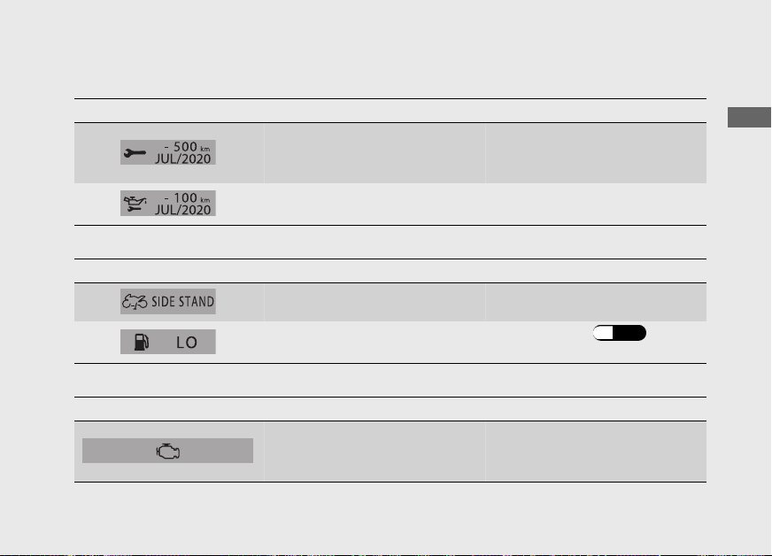
Maintenance Information
#
Indication Explanation Remedy
Helpful Information
#
Indication Explanation Remedy
When the periodic inspection
time of your vehicle is
approaching.
When the oil change time of
your vehicle is approaching.
When the side stand is down. Raise the side stand.
Have your vehicle inspected by
your dealer.
Change the engine oil.
Operation Guide
Failure Information
#
Indication Explanation Remedy
When remaining fuel is reached
4.0 L (1.1 US gal, 0.9 Imp gal).
When your vehicle has a
problem with the PGM-FI
system.
Fill the fuel tank. (P.98)
Reduce speed and have your
vehicle inspected by your dealer
as soon as possible.
79
Page 84
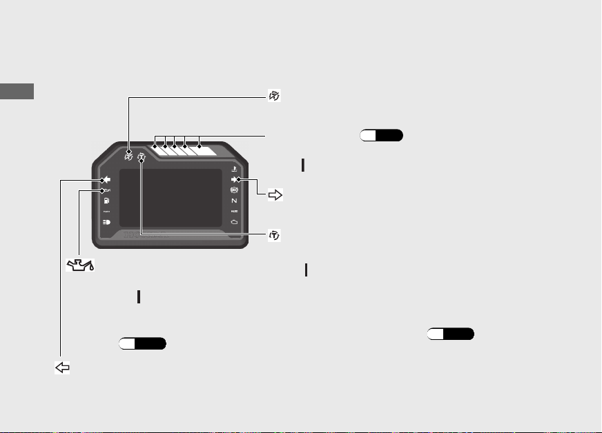
Indicators
If one of these indicators does not come on when it should, have your dealer check for
problems.
Operation Guide
Low oil pressure indicator
Comes on when the ignition switch is
turned to the
when the engine starts.
If it comes on while engine is
running: (P.148)
Left turn signal indicator
80
(On) position. Goes off
Torque Control OFF indicator
Comes on when the Torque Control is turned off.
Shift indicators (P.83)
Comes on briefly when the ignition switch is turned
to the
(On) position.
Right turn signal indicator
Torque Control indicator
● Comes on when the ignition switch is turned to
the
(On) position. Goes off when your speed
reaches approximately 5 km/h (3 mph) to
indicate Torque Control is ready to work.
● Blinks when Torque Control is operating.
If it comes on while riding: (P.150)
Page 85
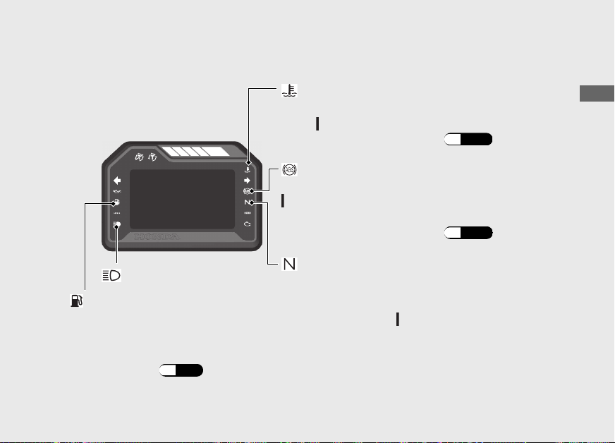
High coolant temperature indicator
Comes on briefly when the ignition switch is turned
to the
(On) position.
If it comes on while riding: (P.147
)
ABS (Anti-lock Brake System) indicator
Comes on when the ignition switch is turned to the
(On) position. Goes off when your speed reaches
approximately 10 km/h (6 mph).
If it comes on while riding: (P.149)
Operation Guide
High beam indicator
Comes on when the transmission is in Neutral.
Low fuel indicator
Neutral indicator
● Comes on briefly when the ignition switch is turned to the (On) position.
● Comes on when there is only reserve fuel left in the fuel tank. Remaining fuel when low
fuel indicator comes on: 4.0 L (1.1 US gal, 0.9 Imp gal)
If it comes on: (P.37)
Continued
81
Page 86
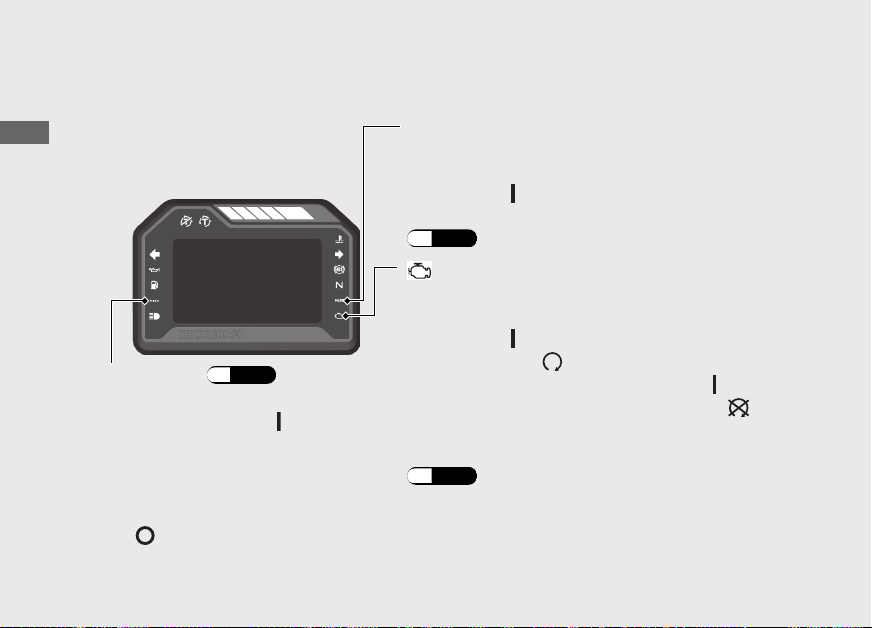
Indicators (Continued)
Operation Guide
HISS indicator (P.146)
● Comes on briefly when the ignition
switch is turned to the
position. Goes off if the ignition
key has the correct coding.
● Flashes every 2 seconds for 24 hours
when the ignition switch is turned to
the
(Off) position.
82
(On)
HESD (Honda Electronic Steering Damper)
indicator
Comes on briefly when the ignition switch is
turned to the
(On) position.
If it comes on while engine is running:
(P.149)
PGM-FI (Programmed Fuel Injection)
malfunction indicator lamp (MIL)
Comes on briefly when the ignition switch is
turned to the
(On) position with the engine
stop switch in the (Run) position. Comes on
when the ignition switch is turned to the (On)
position with the engine stop switch in the
(Stop) position.
If it comes on while engine is running:
(P.148)
Page 87
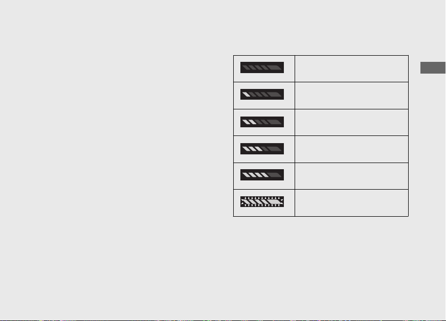
Shift Indicators
The shift indicators light or blink by the
engine revolutions. The first indicator lights
when the engine revolutions reach a number
800 r/min (rpm) below a preset revolution
number.
The second, third and fourth indicators will
light each time the engine revolutions is 200
r/min (rpm) rise.
All indicators will blink when engine
revolutions is reached the set value.
Setting of the Shift Indicators
You can change the engine revolutions at
which the shift indicators start blinking.
Initial setting: OFF
Available setting range:
4,000 - 17,500 r/min (rpm)
Example set value: 11,600 r/min (rpm)
0 to 10,800 r/min (rpm)
All indicators go off
10,800 r/min (rpm)
First indicator comes on
11,000 r/min (rpm)
Second indicator comes on
11,200 r/min (rpm)
Third indicator comes on
11,400 r/min (rpm)
Fourth indicator comes on
11,600 r/min (rpm)
All indicators blink
Operation Guide
83
Page 88
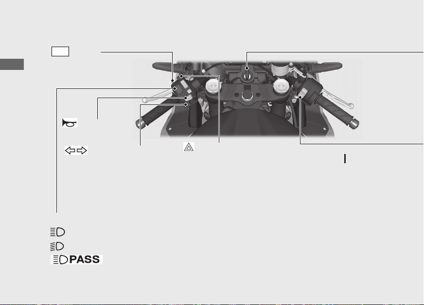
Switches
LAP
button
Operation Guide
Operate the lap timer
Horn button
Turn signal switch
u Pressing the switch turns
the turn signal off.
Headlight dimmer switch/Passing light control switch
• : High beam
• : Low beam
• : Flashes the high beam headlight.
84
Hazard switch
Switchable when the ignition switch is in the (On)
position.
Page 89
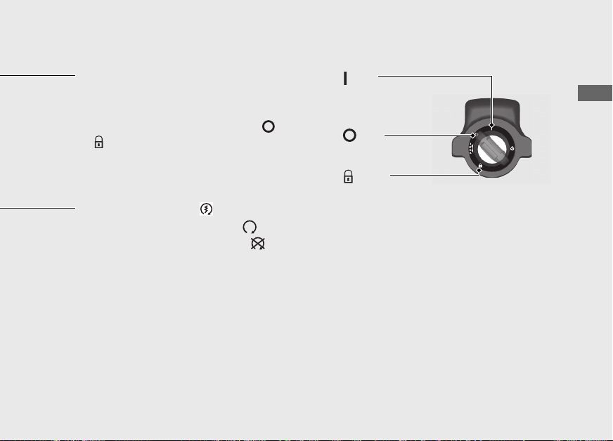
Ignition switch
Switches the electrical system on/off, locks
the steering.
u Key can be removed when in the (Off) or
(Lock) position.
(On)
Turns electrical system
on for starting/riding.
(Off)
Turns engine off.
(Lock)
Locks steering.
Engine stop switch/ Start button
Should normally remain in the (Run) position.
u In an emergency, switch to the (Stop) position to stop the engine.
Operation Guide
Continued
85
Page 90
Switches (Continued)
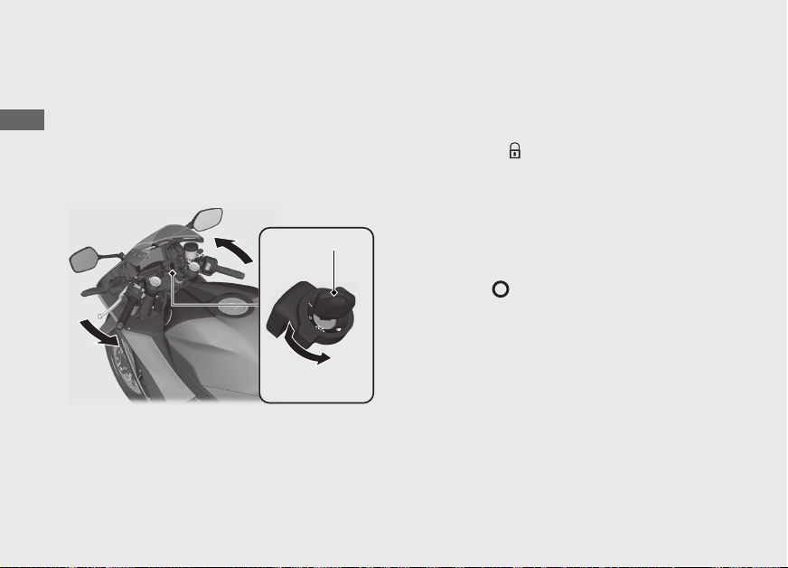
Steering Lock
Lock the steering when parking to help
Operation Guide
prevent theft.
A U-shaped wheel lock or similar device is
also recommended.
Locking
#
a
Turn the handlebars all the way to the left.
b
Push the key down, and turn the ignition
switch to the (Lock) position.
u Jiggle the handlebars if the lock is
difficult to engage.
c
Remove the key.
86
a
Ignition key
Push
Turn
b
Unlocking
#
Insert the key, push it in, and turn the ignition
switch to the (Off) position.
Page 91
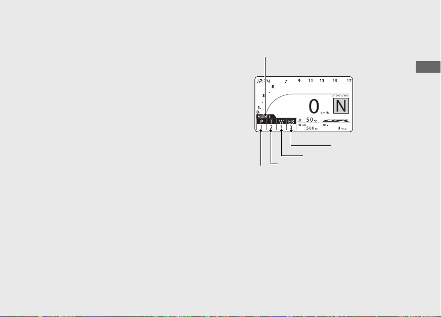
Riding mode
You can change the riding mode.
The riding mode consists of the following
parameters.
P: Engine output level
T: Torque control level
W: Wheelie control level
EB: Engine brake level
Current riding mode
Operation Guide
When “-” is displayed, go to your dealer for
service.
P value
T value
W value
EB value
Continued
87
Page 92
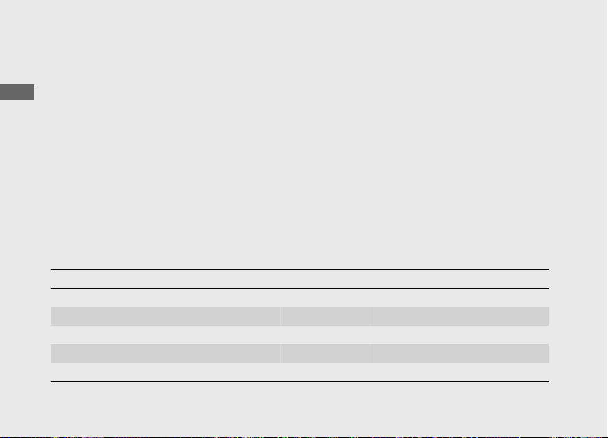
Riding mode (Continued)
Riding mode has five modes.
Available riding mode: MODE 1, MODE 2,
MODE 3, USER 1 and USER 2.
Operation Guide
Initial setting
Riding modes P value T value W value EB value
MODE 1 1 2 1 3
MODE 2 2 5 2 3
MODE 3 5 8 3 1
USER 1 1
Notes:
*1 : Value can be changed
88
USER 2 2
MODE 1, MODE 2 and MODE 3
u
MODE 1 is suitable for track riding.
u MODE 2 is suitable for winding roads.
MODE 3 is suitable for street riding.
u
Each value can not be changed.
USER 1 and USER 2
Each value can be changed.
*1
*1
*1
5
*1
5
*1
2
*1
2
*1
1
*1
2
Page 93
P value (Engine output level)
P value has five setting levels.
Available setting range: 1 to 5
u Level 1 has the most power.
u Level 5 has the least power.
T value (Torque control level)
T value has ten setting levels.
Available setting range: 0 to 9
u Level 1 is the minimum Torque Control level.
u Level 9 is the maximum Torque Control
level.
u Level 0 deactivates the Torque Control.
u When the T value is set to 0, the W value
automatically changes 0.
W value (Wheelie control level)
W value has four setting levels.
Available setting range: 1 to 3
u
Level 1 is the minimum Wheelie Control level.
u
Level 3 is the maximum Wheelie Control level.
u
Level 0 deactivates the Wheelie Control.
EB value (Engine brake level)
EB value has three setting levels.
Available setting range: 1 to 3
u Level 1 has the strongest engine braking
effect.
u Level 3 has the weakest engine braking
effect.
Operation Guide
Continued
89
Page 94
Riding mode (Continued)
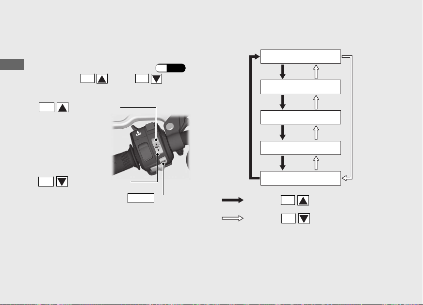
Selecting the riding mode
a
Stop the vehicle.
b
Operation Guide
Select the riding mode display. (P.26)
c
Press the
SEL
(up) or
button with the throttle fully closed.
SEL
(up) button
SEL
(down)
MODE 1
MODE 2
MODE 3
USER 1
90
SEL
(down) button
MODE
button
Press the
Press the
USER 2
SEL
(up) button
SEL
(down) button
Page 95
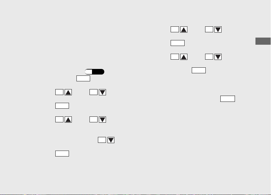
Setting the riding mode
You can change the P, T, W and EB values on
the USER 1 and USER 2 of the riding mode.
a
Stop the vehicle.
b
Select the USER 1 or USER 2 in the riding
mode you want to set. (P.88)
c
Press and hold the
MODE
button until P
value is selected.
d
Press the
SEL
(up) or
SEL
(down)
button until the desired value is displayed.
e
Press the
MODE
button until T value is
selected.
f
Press the
SEL
(up) or
SEL
(down)
button until the desired value is displayed.
u T value can be changed to level 0 by
SEL
pressing and holding the
(down)
button at the time of level 1.
g
Press the
MODE
button until W value is
selected.
h
Press the
SEL
(up) or
SEL
(down)
button until the desired value is displayed.
i
Press the
MODE
button until EB value is
selected.
j
Press the
SEL
(up) or
SEL
(down)
button until the desired value is displayed.
k
Press and hold the
MODE
button until
ordinary display is displayed.
You can stop setting the riding modes at any
time by pressing and holding the
MODE
button.
Operation Guide
Continued
91
Page 96
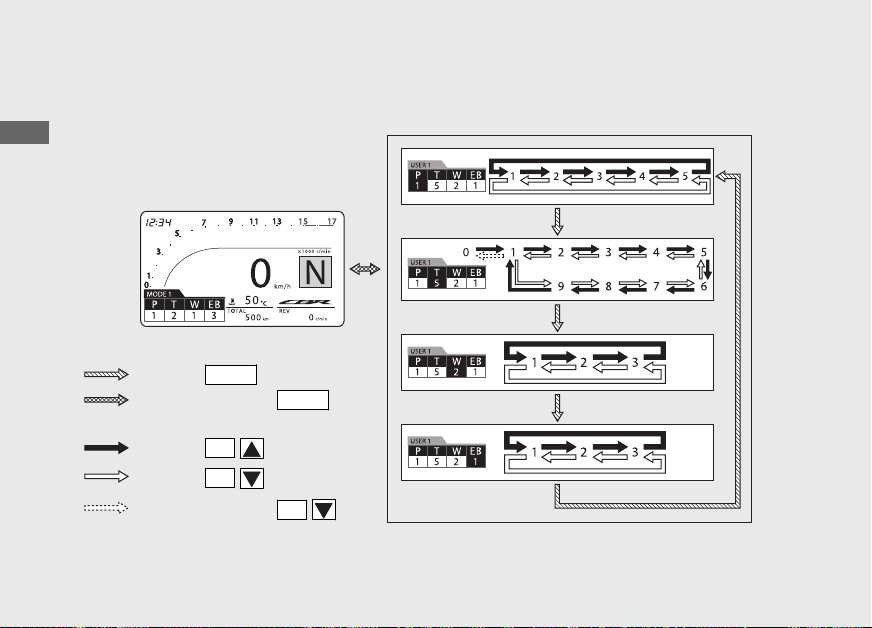
Riding mode (Continued)
Operation Guide
92
Press the
MODE
button
Press and hold the
button
Press the
Press the
SEL
(up) button
SEL
(down) button
Press and hold the
(down) button
MODE
SEL
Page 97
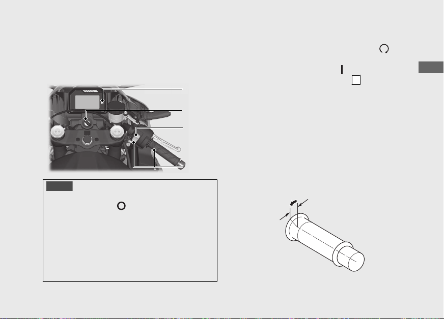
Starting the Engine
Start your engine using the following
procedure, regardless of whether the engine
is cold or warm.
c
b
a
a
Make sure the engine stop switch is in the
(Run) position.
b
Turn the ignition switch to the (On) position.
c
Shift the transmission to Neutral ( N indicator
comes on). Alternatively, pull in the clutch lever to
start your vehicle with the transmission in gear so
long as the side stand is raised.
d
Press the start button with the throttle completely
closed.
Operation Guide
d
NOTICE
•
If the engine does not start within 5 seconds, turn the
ignition switch to the (Off) position and wait 10
seconds before trying to start the engine again to
recover battery voltage.
•
Extended fast idling and revving the engine can
damage the engine, and the exhaust system.
Snapping the throttle or fast idling for more than about
•
5 minutes may cause exhaust pipe discolouration.
•
The engine will not start if the throttle is fully open.
If you cannot start the engine:
With the throttle slightly open (about 3 mm,
without freeplay) while starting the engine.
About 3 mm, without freeplay
Continued
93
Page 98

Starting the Engine (Continued)
If the engine does not start:
a
Open the throttle fully and press the start
Operation Guide
button for 5 seconds.
b
Repeat the normal starting procedure.
c
If the engine starts, open the throttle slightly
if idling is unstable.
d
If the engine does not start, wait 10 seconds
before trying steps a & b again.
If Engine Will Not Start (P.146)
#
94
Page 99
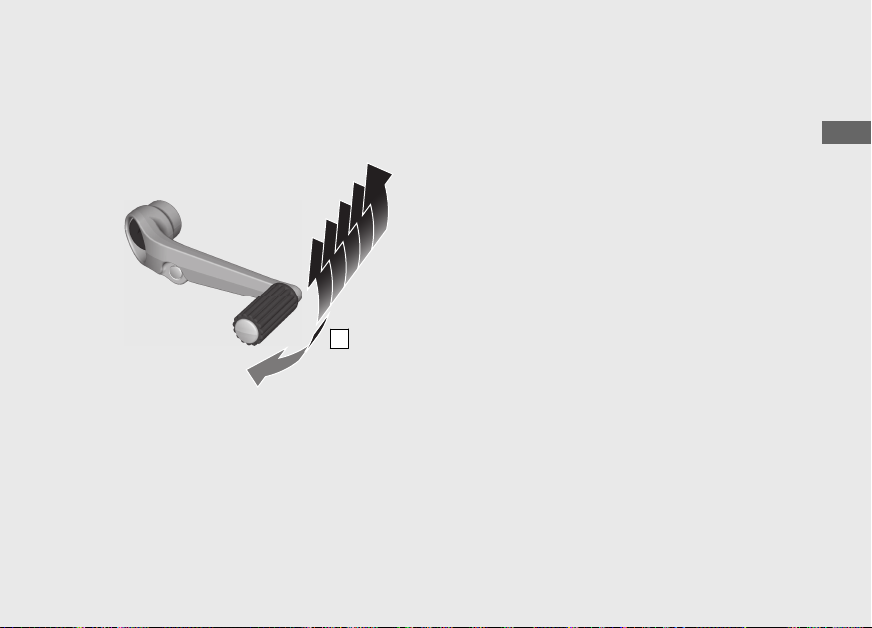
Shifting Gears
Your vehicle transmission has 6 forward
gears in a one-down, five-up shift pattern.
6
5
4
3
2
N
1
If you put the vehicle in gear with the side
stand down, the engine will shut off.
Operation Guide
95
Page 100
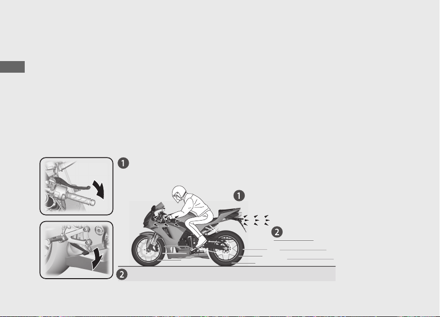
Emergency Stop Signal
Emergency stop signal activates when the
system detects hard braking about 50 km/h
(31 mph) or above to alert drivers behind you
Operation Guide
about sudden braking by rapidly flashing
both turn signal lights. This may help to alert
drivers behind you to take appropriate
means to avoid a possible collision with your
vehicle.
When the system activates:
Hard braking
Both turn signal indicators blink
96
The emergency stop signal stops operating
when:
● You release the brakes.
● The ABS is deactivated.
● Your vehicle's decelerating speed
becomes moderate.
● You press the hazard switch.
Brakelight comes on
Both turn signals flash
 Loading...