

Page 1
1. GENERAL INFORMATION
1
SERVICE RULES ········································· 1-2
MODEL IDENTIFICATION··························· 1-3
GENERAL SPECIFICATIONS······················ 1-5
LUBRICATION SYSTEM
SPECIFICATIONS········································ 1-7
FUEL SYSTEM (PGM-FI)
SPECIFICATIONS········································ 1-7
COOLING SYSTEM SPECIFICATIONS ······ 1-7
CYLINDER HEAD/VALVES
SPECIFICATIONS········································ 1-8
CLUTCH/STARTER CLUTCH
SPECIFICATIONS········································ 1-8
TRANSMISSION/GEARSHIFT LINKAGE
SPECIFICATIONS········································ 1-9
CRANKCASE/CRANKSHAFT/BALANCER/
PISTON/CYLINDER SPECIFICATIONS ······ 1-9
FRONT WHEEL/SUSPENSION/STEERING
SPECIFICATIONS ····································· 1-10
REAR WHEEL/SUSPENSION
SPECIFICATIONS ····································· 1-10
HYDRAULIC BRAKE SPECIFICATIONS··· 1-11
BATTERY/CHARGING SYSTEM
SPECIFICATIONS ····································· 1-11
IGNITION SYSTEM SPECIFICATIONS ···· 1-11
ELECTRIC STARTER SPECIFICATIONS ·· 1-11
LIGHTS/METERS/SWITCHES
SPECIFICATIONS ····································· 1-12
STANDARD TORQUE VALUES ··············· 1-13
ENGINE & FRAME TORQUE VALUES ···· 1-13
LUBRICATION & SEAL POINTS ·············· 1-20
CABLE & HARNESS ROUTING ··············· 1-23
EMISSION CONTROL SYSTEMS ············ 1-42
1-1
Page 2
GENERAL INFORMATION
GENERAL INFORMATION
SERVICE RULES
1. Use genuine Honda or Honda-recommended parts and lubricants or their equivalents. Parts that don't meet Honda's
design specifications may cause damage to the motorcycle.
2. Use the special tools designed for this product to avoid damage and incorrect assembly.
3. Use only metric tools when servicing the motorcycle. Metric bolts, nuts and screws are not interchangeable with
English fasteners.
4. Install new gaskets, O-rings, cotter pins, and lock plates when reassembling.
5. When tightening bolts or nuts, begin with the larger diameter or inner bolt first. Then tighten to the specified torque
diagonally in incremental steps unless a particular sequence is specified.
6. Clean parts in cleaning solvent upon disassembly. Lubricate any sliding surfaces before reassembly.
7. After reassembly, check all parts for proper installation and operation.
8. Route all electrical wires as shown in the Cable and Harness Routing (page 1-23).
ABBREVIATION
Throughout this manual, the following abbreviations are used to identify the respective parts or systems.
Abbrev. term Full term
PGM-FI Programmed Fuel Injection
MAP sensor Manifold Absolute Pressure sensor
TP sensor Throttle Position sensor
ECT sensor Engine Coolant Temperature sensor
IAT sensor Intake Air Temperature sensor
CKP sensor Crankshaft Position sensor
VS sensor Vehicle Speed sensor
IACV Idle Air Control Valve
ECM Engine Control Module
EEPROM Electrically Erasable Programmable Read Only Memory
DLC Data Link Connector
SCS connector Service Check Short connector
HDS Honda Diagnostic System
DTC Diagnostic Trouble Code
MIL Malfunction Indicator Lamp
FP Fuel Pump
PAIR Pulsed Secondary Air Injection
ABS Anti-lock Brake System
HISS Honda Ignition Security System
1-2
Page 3
MODEL IDENTIFICATION
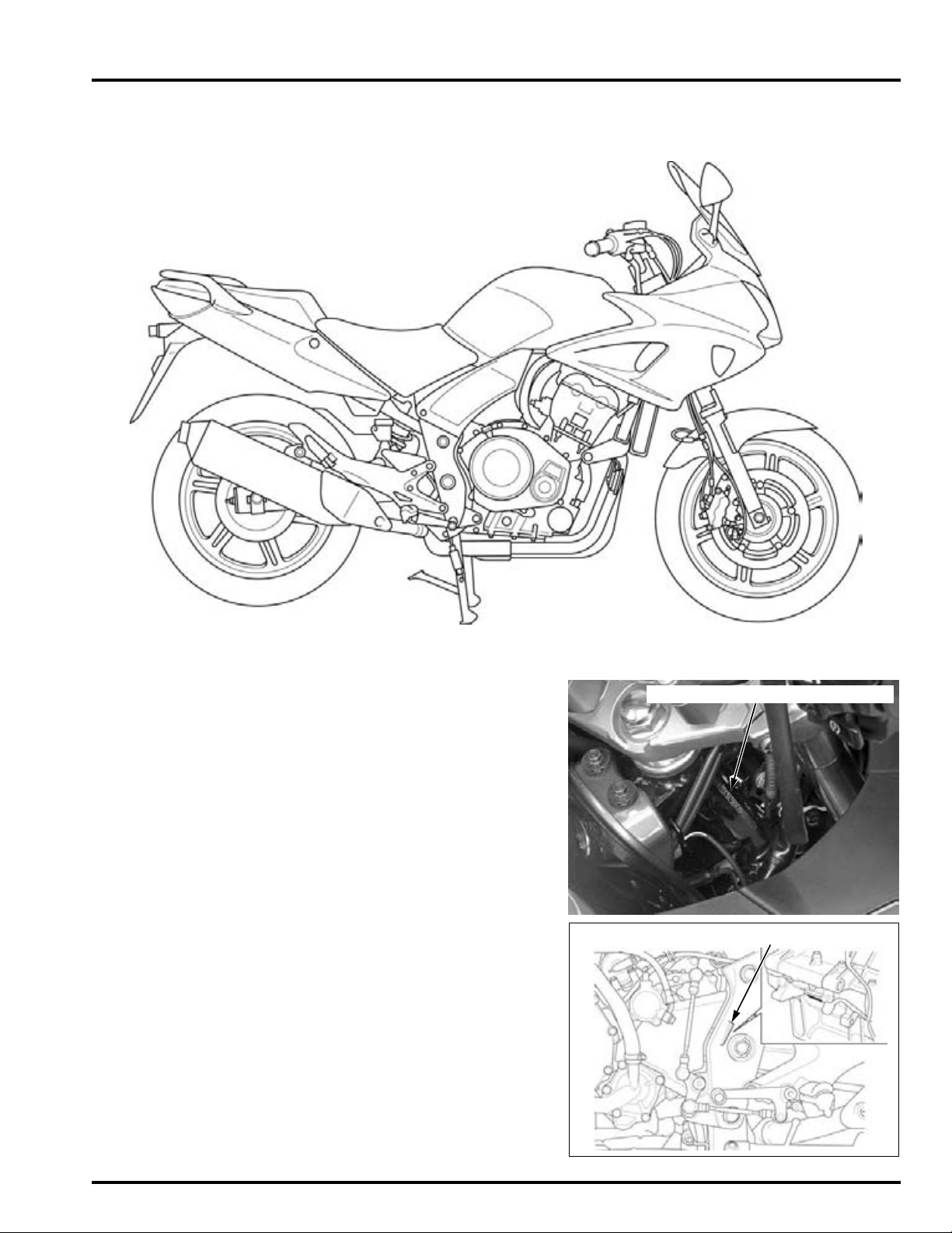
VEHICLE IDENTIFICATION NUMBER
ENGINE SERIAL NUMBER
CBF1000A Shown:
GENERAL INFORMATION
SERIAL NUMBERS
The Vehicle Identification Number (V.I.N) is stamped on the right side
of the steering head.
The engine serial number is stamped on the lower side of the lower
crankcase.
1-3
Page 4
GENERAL INFORMATION
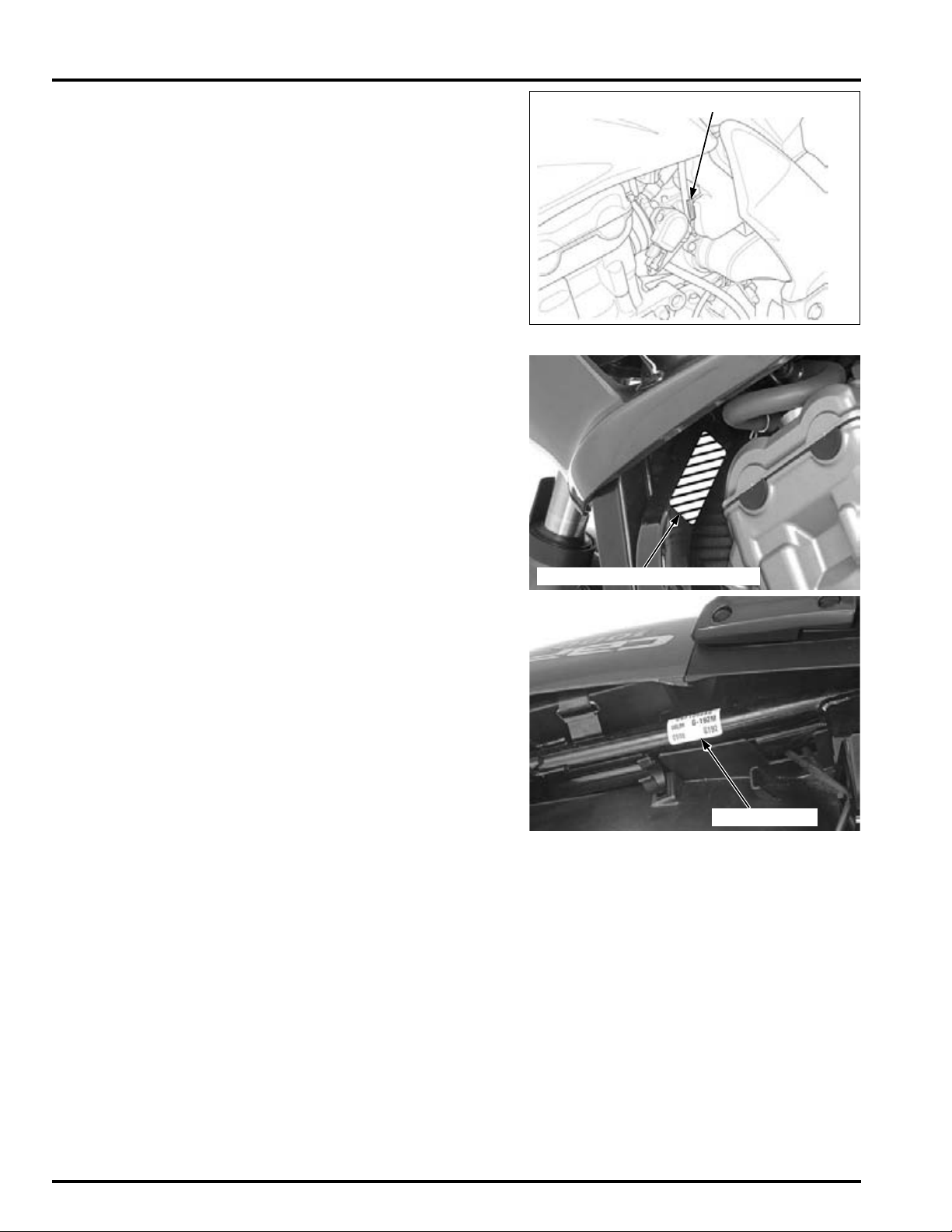
THROTTLE BODY IDENTIFICATION NUMBER
MODEL IDENTIFICATION LABEL
COLOR LABEL
The throttle body identification number is stamped on the intake side
of the throttle body as shown.
LABELS
The Model Identification Label is located on left side of the frame tube.
The color label is attached as shown. When ordering color-coded
parts, always specify the designated color code.
1-4
Page 5
GENERAL INFORMATION
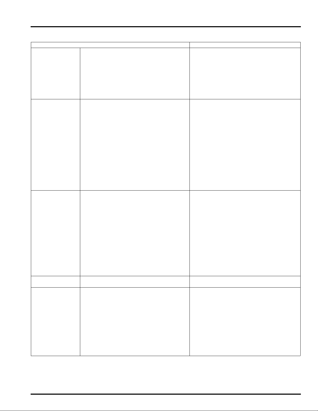
GENERAL SPECIFICATIONS
ITEM SPECIFICATIONS
DIMENSIONS Overall length 2,156 mm (84.9 in)
Overall width 782 mm (30.8 in)
Overall height 1,238 mm (48.7 in)
Wheelbase 1,483 mm (58.4 in)
Seat height 800 mm (31.5 in)
Ground clearance 130 mm (5.1 in)
Curb weight CBF1000: 244 kg (538 lbs)
CBF1000A: 251 kg (553 lbs)
Maximum weight capacity 195 kg (430 lbs)
FRAME Frame type Diamond type
Front suspension Telescopic fork
Front axle travel 108 mm (4.3 in)
Rear suspension Swingarm
Rear axle travel 120 mm (4.7 in)
Front tire size 120/70ZR17M/C (58W)
Rear tire size 160/60ZR17M/C (69W)
Front tire brand Bridgestone BT57F RADIAL U
Michelin Pilot ROAD B
Rear tire brand Bridgestone BT57R RADIAL E
Michelin Pilot ROAD A
Front brake Hydraulic double disc
Rear brake Hydraulic single disc
Caster angle 26° 00’
Trail length 111 mm (4.4 in)
Fuel tank capacity 19.3 liter (5.1 US gal, 4.2 lmp gal)
ENGINE Cylinder arrangement 4 cylinders in-line, inclined 28° from vertical
Bore and stroke 75.0 x 56.5 mm (2.95 x 2.22 in)
Displacement 998.4 cm
Compression ratio 11.0 : 1
Valve train Chain driven, DOHC
Intake
valve
Exhaust
valve
Lubrication system Forced pressure and wet sump
Oil pump type Trochoid
Cooling system Liquid cooled
Air filtration Paper element
Engine dry weight 66.5 kg (146.6 lbs)
Firing order 1 - 2 - 4 - 3
FUEL DELIVERY
SYSTEM
DRIVE TRAIN Clutch system Multi-plate, wet
Type PGM-FI (Programmed Fuel Injection)
Throttle bore 36 mm (1.4 in)
Clutch operation system Hydraulic operating
Transmission Constant mesh, 6-speeds
Primary reduction 1.604 (77/48)
Final reduction 2.687 (43/16)
Gear ratio 1st 2.714 (38/14)
Gearshift pattern 1 - N - 2 - 3 - 4 - 5 - 6
opens: at 1 mm (0.04 in) lift 15° BTDC
closes: at 1 mm (0.04 in) lift 15° ABDC
opens: at 1 mm (0.04 in) lift 25° BBDC
closes: at 1 mm (0.04 in) lift 5° ATDC
2nd 1.941 (33/17)
3rd 1.578 (30/19)
4th 1.363 (30/22)
5th 1.217 (28/23)
6th 1.115 (29/26)
3
(60.92 cu-in)
1-5
Page 6

GENERAL INFORMATION
ITEM SPECIFICATIONS
ELECTRICAL Ignition system Computer-controlled digital transistorized
with electric advance
Starting system Electric starter motor
Charging system Triple phase output alternator
Regulator/rectifier FET shorted/triple phase, full wave rectifica-
Lighting system Battery
tion
1-6
Page 7
GENERAL INFORMATION
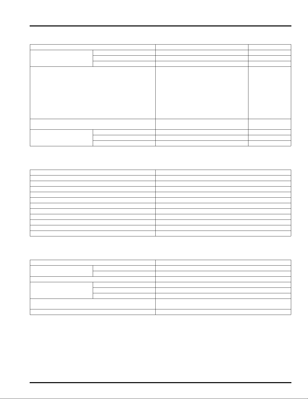
LUBRICATION SYSTEM SPECIFICATIONS
Unit: mm (in)
ITEM STANDARD SERVICE LIMIT
Engine oil capacity After draining 2.7 liter (2.9 US qt, 2.4 lmp qt) –
After oil filter change 3.5 liter (3.7 US qt, 3.1 lmp qt) –
After disassembly 3.6 liter (3.8 US qt, 3.2 lmp qt) –
Engine oil Suggested oil: –
Honda "4-stroke motorcycle oil" or
an equivalent
Oil recommendation:
API classification: SG or higher
(except oils labeled as energy conserving on the circular API service
label)
Viscosity: SAE 10W-30
JASO T 903 standard: MA
Oil pressure at EOP (engine oil pressure) switch 510 kPa (5.2 kgf/cm
6,000 min
Oil pump Tip clearance 0.15 (0.006) 0.20 (0.008)
Body clearance 0.15 – 0.21 (0.006 – 0.008) 0.35 (0.014)
Side clearance 0.04 – 0.09 (0.002 – 0.004) 0.17 (0.007)
-1
(rpm)/(80°C/176°F)
2
, 74 psi) at
FUEL SYSTEM (PGM-FI) SPECIFICATIONS
–
ITEM SPECIFICATIONS
Throttle body identification number GQ3BA
Idle speed 1,200 ± 10 0 min
Throttle grip free play 2 – 6 mm (1/12 – 1/4 in)
IAT sensor resistance (at 20°C/68°F) 1 – 4 kΩ
ECT sensor resistance (at 20°C/68°F) 2.3 – 2.6 kΩ
Fuel injector resistance (at 20°C /68°F) 11.1 – 12.3 Ω
PAIR control solenoid valve resistance (at 20°C/68°F) 23 – 27 Ω
CKP sensor peak voltage (at 20°C/68°F) 0.7 V minimum
Manifold absolute pressure at idle 29 – 32 kPa (0.30 – 0.33 kgf/cm
Fuel pressure at idle 343 kPa (3.5 kgf/cm
Fuel pump flow (at 12 V) 189 cm
3
(6.4 US oz, 6.7 lmp oz) minimum/10 seconds
-1
(rpm)
2
, 4.3 – 4.7 psi)
2
, 50 psi)
COOLING SYSTEM SPECIFICATIONS
ITEM SPECIFICATIONS
Coolant capacity Radiator and engine 2.71 liter (2.86 US qt, 2.38 lmp qt)
Reserve tank 0.30 liter (0.32 US qt, 0.26 lmp qt)
Radiator cap relief pressure 108 – 137 kPa (1.1 – 1.4 kgf/cm
Thermostat Begin to open 80 – 84 °C (176 – 183 °F)
Fully open 90 °C (194 °F)
Valve lift 8 mm (0.3 in) minimum
Recommended antifreeze High quality ethylene glycol antifreeze containing corrosion
protection inhibitors
Standard coolant concentration 1:1 mixture with distilled water
2
, 16 – 20 psi)
1-7
Page 8
GENERAL INFORMATION
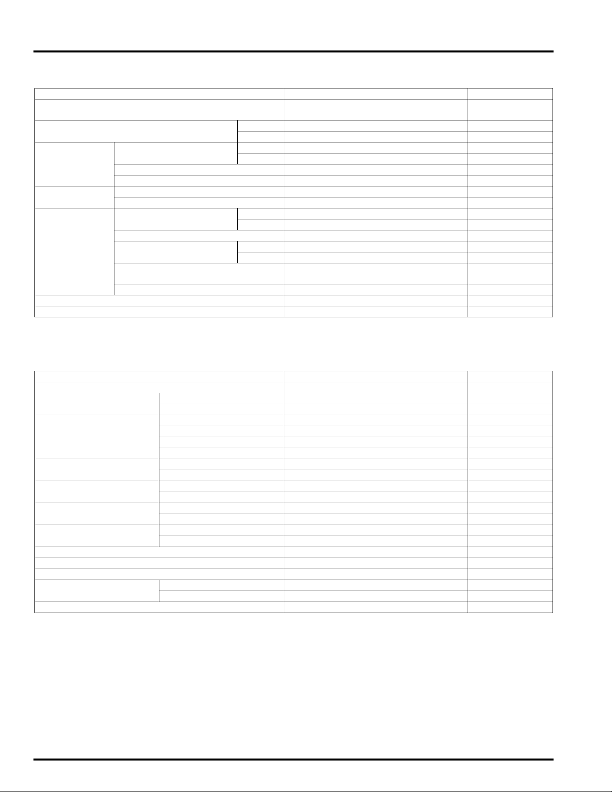
CYLINDER HEAD/VALVES SPECIFICATIONS
Unit: mm (in)
ITEM STANDARD SERVICE LIMIT
Cylinder compression 1,098 kPa (11.2 kgf/cm2, 159 psi)
Valve clearance IN 0.16 ± 0.03 (0.006 ± 0.001) –
EX 0.32 ± 0.03 (0.013 ± 0.001) –
Camshaft Cam lobe height IN 34.62 – 34.70 (1.363 – 1.366) 34.60 (1.362)
EX 34.58 – 34.66 (1.361 – 1.365) 34.56 (1.361)
Runout – 0.05 (0.002)
Oil clearance 0.020 – 0.062 (0.0008 – 0.0024) 0.10 (0.004)
Valve lifter Valve lifter O.D. 25.978 – 25.993 (1.0228 – 1.0233) 25.97 (1.022)
Valve lifter bore I.D. 26.010 – 26.026 (1.0240 – 1.0246) 26.04 (1.025)
Valve,
valve guide
Valve spring free length 39.55 (1.557) 38.76 (1.526)
Cylinder head warpage – 0.10 (0.004)
Valve stem O.D. IN 4.475 – 4.490 (0.1762 – 0.1768) 4.465 (0.1758)
EX 4.465 – 4.480 (0.1758 – 0.1764) 4.455 (0.1754)
Valve guide I.D. 4.500 – 4.512 (0.1772 – 0.1776) 4.540 (0.1787)
Stem-to-guide clearance IN 0.010 – 0.037 (0.0004 – 0.0015) 0.075 (0.0030)
EX 0.020 – 0.047 (0.0008 – 0.0019) 0.085 (0.0033)
Valve guide projection above cylin-
der head
Valve seat width 0.90 – 1.10 (0.035 – 0.043) 1.5 (0.06)
at 350 min
16.0 – 16.3 (0.63 – 0.64) –
-1
(rpm)
–
CLUTCH/STARTER CLUTCH SPECIFICATIONS
Unit: mm (in)
ITEM STANDARD SERVICE LIMIT
Specified clutch fluid DOT 4 brake fluid –
Clutch master cylinder Master cylinder I.D. 12.700 – 12.743 (0.5000 – 0.5017) 12.755 (0.5022)
Master piston O.D. 12.657 – 12.684 (0.4983 – 0.4994) 12.645 (0.4978)
Clutch Spring free length 58.2 (2.29) 55.7 (2.19)
Disc A thickness 3.72 – 3.88 (0.146 – 0.153) 3.4 (0.13)
Disc B thickness 3.22 – 3.38 (0.127 – 0.133) 2.9 (0.11)
Plate warpage – 0.30 (0.012)
Clutch outer guide A
(Without ID mark)
Clutch outer guide B
(With ID mark)
Primary driven gear I.D. A 41.008 – 41.016 (1.6145 – 1.6148) 41.026 (1.6152)
Oil pump drive sprocket
guide
Oil pump drive sprocket I.D. 35.025 – 35.145 (1.3789 – 1.3837) 35.155 (1.3841)
Mainshaft O.D. at clutch outer guide 27.980 – 27.990 (1.1016 – 1.1020) 27.96 (1.101)
Mainshaft O.D. at oil pump drive sprocket guide 27.980 – 27.990 (1.1016 – 1.1020) 27.96 (1.101)
Starter idle gear Gear I.D. 10.013 – 10.035 (0.3942 – 0.3951) 10.05 (0.396)
Starter driven gear boss O.D. 45.657 – 45.673 (1.7975 – 1.7981) 45.642 (1.7969)
I.D. 27.993 – 28.003 (1.1021 – 1.1025) 28.012 (1.1028)
O.D. 35.004 – 35.012 (1.3781 – 1.3784) 34.994 (1.3777)
I.D. 27.993 – 28.003 (1.1021 – 1.1025) 28.012 (1.1028)
O.D. 34.996 – 35.004 (1.3778 – 1.3781) 34.986 (1.3774)
B 41.000 – 41.008 (1.6142 – 1.6145) 41.018 (1.6149)
I.D. 28.000 – 28.021 (1.1024 – 1.1032) 28.030 (1.1035)
O.D. 34.975 – 34.991 (1.3770 – 1.3776) 34.965 (1.3766)
Shaft O.D. 9.991 – 10.000 (0.3933 – 0.3937) 9.98 (0.393)
1-8
Page 9
GENERAL INFORMATION
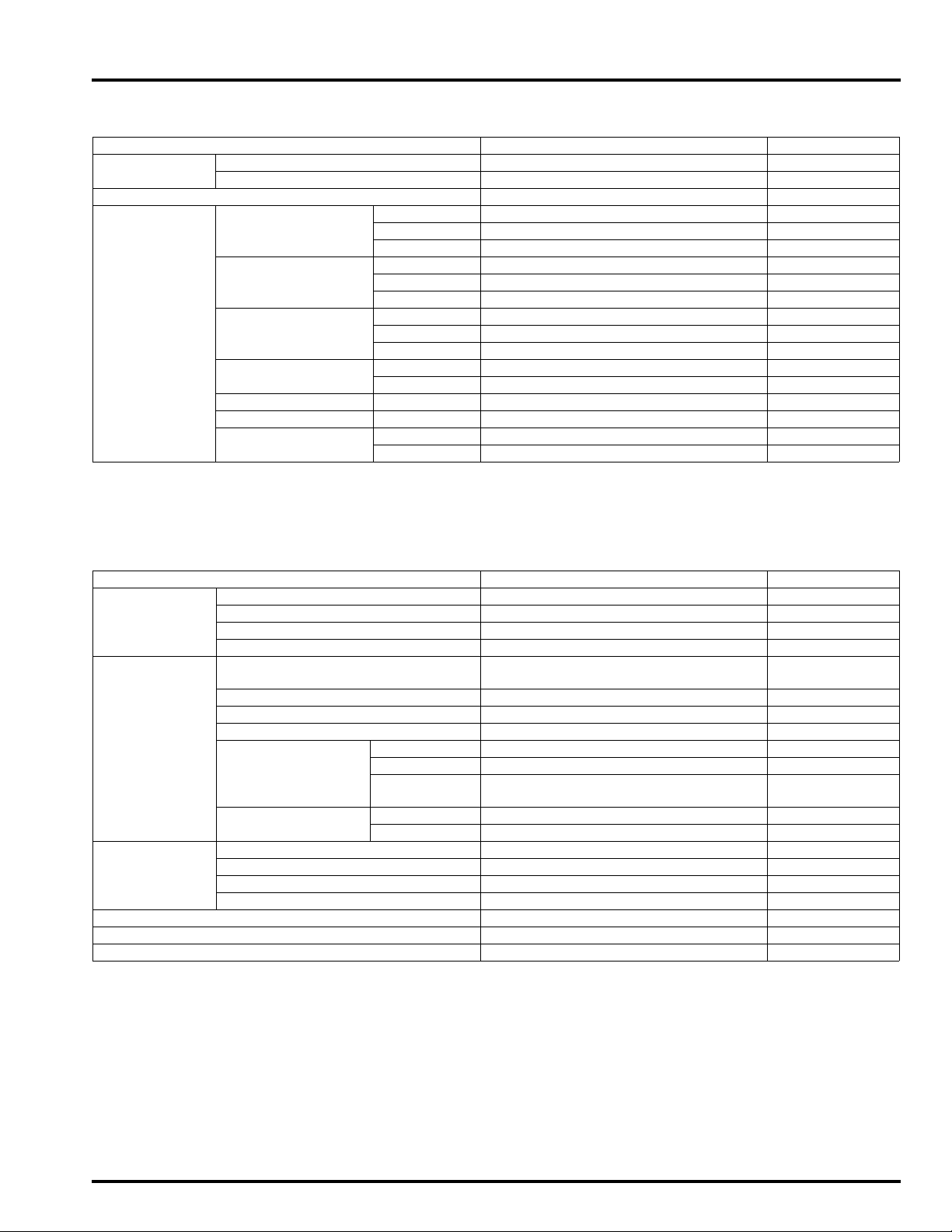
TRANSMISSION/GEARSHIFT LINKAGE SPECIFICATIONS
Unit: mm (in)
ITEM STANDARD SERVICE LIMIT
Shift fork I.D. 12.000 – 12.018 (0.4724 – 0.4731) 12.03 (0.474)
Claw thickness 5.93 – 6.00 (0.233 – 0.236) 5.9 (0.23)
Shift fork shaft O.D. 11.957 – 11.968 (0.4707 – 0.4712) 11.95 (0.470)
Transmission Gear I.D. M5, M6 31.000 – 31.025 (1.2205 – 1.2215) 31.04 (1.222)
C1 28.000 – 28.021 (1.1024 – 1.1032) 28.04 (1.104)
C2, C3, C4 33.000 – 33.025 (1.2992 – 1.3002) 33.04 (1.301)
Gear busing O.D. M5, M6 30.955 – 30.980 (1.2187 – 1.2197) 30.935 (1.2179)
C2 32.955 – 32.980 (1.2974 – 1.2984) 32.935 (1.2967)
C3, C4 32.950 – 32.975 (1.2972 – 1.2982) 32.930 (1.2964)
Gear-to-bushing
clearance
Gear bushing I.D. M5 27.985 – 28.006 (1.1018 – 1.1026) 28.016 (1.1030)
Mainshaft O.D. at M5 27.967 – 27.980 (1.1011 – 1.1016) 27.957 (1.1007)
Countershaft O.D. at C2 29.967 – 29.980 (1.1798 – 1.1803) 29.960 (1.1795)
Bushing to shaft
clearance
M5, M6 0.020 – 0.070 (0.0008 – 0.0028) 0.10 (0.004)
C2 0.020 – 0.070 (0.0008 – 0.0028) 0.10 (0.004)
C3, C4 0.025 – 0.075 (0.0010 – 0.0030) 0.11 (0.004)
C2 29.985 – 30.006 (1.1018 – 1.1026) 30.021 (1.1819)
M5 0.005 – 0.039 (0.0002 – 0.0015) 0.06 (0.002)
C2 0.005 – 0.039 (0.0002 – 0.0015) 0.06 (0.002)
CRANKCASE/CRANKSHAFT/BALANCER/PISTON/CYLINDER
SPECIFICATIONS
Unit: mm (in)
ITEM STANDARD SERVICE LIMIT
Crankshaft Connecting rod side clearance 0.05 – 0.20 (0.002 – 0.008) 0.25 (0.098)
Crankpin bearing oil clearance 0.030 – 0.052 (0.0012 – 0.0020) 0.06 (0.002)
Main journal bearing oil clearance 0.019 – 0.037 (0.0007 – 0.0015) 0.05 (0.002)
Runout – 0.05 (0.002)
Piston, piston
rings
Cylinder I.D. 75.000 – 75.015 (2.9528 – 2.9533) 75.15 (2.959)
Cylinder-to-piston clearance 0.020 – 0.055 (0.0008 – 0.0022) 0.10 (0.004)
Connecting rod small end I.D. 17.030 – 17.042 (0.6705 – 0.6709) 17.048 (0.6712)
Connecting rod-to-piston pin clearance 0.030 – 0.046 (0.0012 – 0.0018) 0.07 (0.003)
Piston O.D. at 9.0 (0.35) from bottom
Piston pin bore I.D. 17.002 – 17.008 (0.6694 – 0.6696) 17.030 (0.6705)
Piston pin O.D. 16.994 – 17.000 (0.6690 – 0.6693) 16.980 (0.6685)
Piston-to-piston pin clearance 0.002 – 0.014 (0.0001 – 0.0006) 0.04 (0.002)
Piston ring end
gap
Piston ring-to-ring
groove clearance
Out of round – 0.10 (0.004)
Taper – 0.10 (0.004)
Warpage – 0.10 (0.004)
Top 0.22 – 0.32 (0.009 – 0.013) 0.52 (0.020)
Second 0.48 – 0.63 (0.019 – 0.025) 0.82 (0.032)
Oil
(side rail)
Top 0.050 – 0.085 (0.0020 – 0.0033) 0.125 (0.0049)
Second 0.015 – 0.050 (0.0006 – 0.0020) 0.075 (0.0030)
74.960 – 74.980 (2.9512 – 2.9520) 74.895 (2.9486)
0.2 – 0.7 (0.01 – 0.03) 1.0 (0.04)
1-9
Page 10
GENERAL INFORMATION
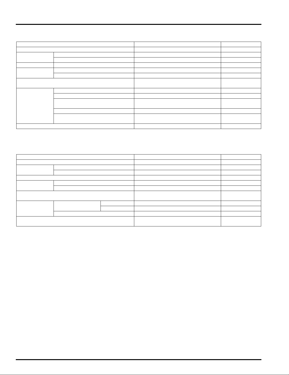
FRONT WHEEL/SUSPENSION/STEERING SPECIFICATIONS
Unit: mm (in)
ITEM STANDARD SERVICE LIMIT
Minimum tire tread depth – 1.5 (0.06)
Cold tire pres-
sure
Axle runout – 0.2 (0.008)
Wheel rim
runout
Wheel balance weight – 60 g (2.1oz)
Fork Spring free length 358.8 (14.13) 352 (13.9)
Steering head bearing pre-load 9.8 – 13.7 N (1.0 – 1.4 kgf, 2.2 – 3.1 lbf) –
Driver only 250 kPa (2.50 kgf/cm
Driver and passenger 250 kPa (2.50 kgf/cm
Radial – 2.0 (0.08)
Axial – 2.0 (0.08)
Fork pipe runout – 0.20 (0.008)
Recommended fork fluid Honda ULTRA CUSHION OIL 10W or
equivalent
Fluid level 129 (5.1) –
Fluid capacity 437 ± 2.5 cm
0.09 lmp oz)
3
(14.8 ± 0.08 US oz, 15.4 ±
2
, 36 psi) –
2
, 36 psi) –
max.
REAR WHEEL/SUSPENSION SPECIFICATIONS
Unit: mm (in)
ITEM STANDARD SERVICE LIMIT
Minimum tire tread depth – 2.0 (0.08)
Cold tire pressure
Axle runout – 0.2 (0.01)
Wheel rim
runout
Wheel balance weight – 60 g
Drive chain Size/link DID DID50VA8/120 links –
Shock absorber spring pre-load adjuster standard
position
Driver only 290 kPa (2.90 kgf/cm2, 42 psi) –
Driver and passenger 290 kPa (2.90 kgf/cm
Radial – 2.0 (0.08)
Axial – 2.0 (0.08)
RK RK50HFOZ5/120 links –
Slack 20 – 30 (4/5 – 1-1/5) –
Position 3 –
2
, 42 psi) –
(2.1 oz) max.
–
–
1-10
Page 11
GENERAL INFORMATION
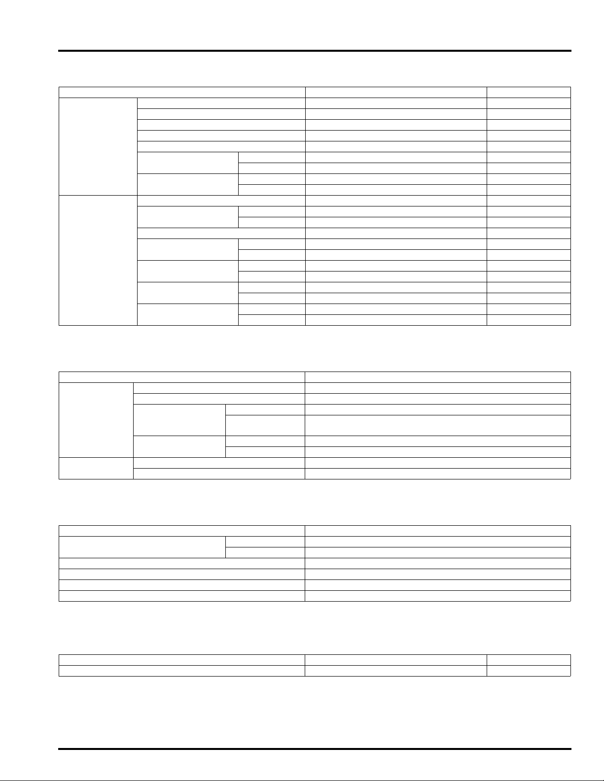
HYDRAULIC BRAKE SPECIFICATIONS
ITEM STANDARD SERVICE LIMIT
Front Specified brake fluid DOT 4 –
Brake disc thickness 4.5 (0.18) 3.5 (0.14)
Brake disc runout – 0.30 (0.012)
Master cylinder I.D. 12.700 – 12.743 (0.5000 – 0.5017) 12.755 (0.5022)
Master piston O.D. 12.657 – 12.684 (0.4983 – 0.4994) 12.650 (0.4980)
Caliper cylinder I.D. CBF1000A: 22.650 – 22.700 (0.8917 – 0.8937) 22.710 (0.8941)
CBF1000: 25.400 – 25.450 (1.0000 – 1.0020) 25.460 (1.0024)
Caliper piston O.D. CBF1000A: 22.585 – 22.618 (0.8892 – 0.8905) 22.560 (0.8882)
CBF1000: 25.318 – 25.368 (0.9968 – 0.9987) 25.310 (0.9965)
Rear Specified brake fluid DOT 4 –
Brake disk thickness
Brake disc runout – 0.30 (0.012)
Master cylinder I.D. CBF1000A: 17.460 17.503 (0.6874 0.6891) 17.515 (0.6896)
Master piston O.D. CBF1000A: 17.417 – 17.444 (0.6857 – 0.6868) 17.405 (0.6852)
Caliper cylinder I.D. CBF1000A: 25.400 – 25.450 (1.0000 – 1.0020) 25.460 (1.0024)
Caliper piston O.D. CBF1000A: 25.318 – 25.368 (0.9968 – 0.9987) 25.310 (0.9965)
CBF1000A: 6.0 (0.24) 5.0 (0.20)
CBF1000: 5.0 (0.20) 4.0 (0.16)
CBF1000: 14.000 – 14.043 (0.5512 – 0.5529) 14.055 (0.5533)
CBF1000: 13.957 – 13.984 (0.5495 – 0.5506) 13.945 (0.5490)
CBF1000: 38.180 – 38.230 (1.5031 – 1.5051) 38.24 (1.506)
CBF1000: 38.098 – 38.148 (1.4999 – 1.5019) 38.09 (1.500)
Unit: mm (in)
BATTERY/CHARGING SYSTEM SPECIFICATIONS
ITEM SPECIFICATIONS
Battery Capacity 12 V – 8.6 Ah
Current leakage 0.5 mA max.
Vol tage
(20°C/68°F)
Charging current Normal 0.9 A/5 – 10 h
Alternator Capacity 0.344 kW/5,000 min
Charging coil resistance (20°C/68°F) 0.1 – 1.0 Ω
Fully charged 13.0 – 13.2 V
Needs
charging
Quick 4.5 A/1 h
Below 12.4 V
-1
(rpm)
IGNITION SYSTEM SPECIFICATIONS
ITEM SPECIFICATIONS
Spark plug NGK CR8EH-9
DENSO U24FER9
Spark plug gap 0.80 – 0.90 mm (0.031 – 0.035 in)
Ignition coil peak voltage 100 V minimum
CKP sensor peak voltage 0.7 V minimum
Ignition timing ("F"mark) 5° BTDC at idle
ELECTRIC STARTER SPECIFICATIONS
ITEM STANDARD SERVICE LIMIT
Starter motor brush length 12.0 – 13.0 (0.47 – 0.51) 6.5 (0.26)
Unit: mm (in)
1-11
Page 12
GENERAL INFORMATION
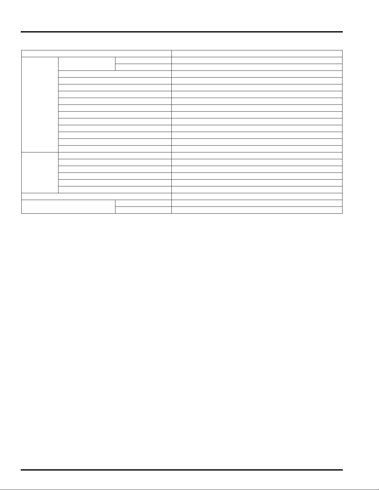
LIGHTS/METERS/SWITCHES SPECIFICATIONS
ITEM SPECIFICATIONS
Bulbs Headlight Hi 12 V – 55 W
Lo 12 V – 55 W
Position light 12 V – 5 W x 2
Brake/tail light 12 V – 21/5 W
Turn signal light 12 V – 21 W x 4
Instrument light LED
Turn signal indicator LED
High beam indicator LED
Oil pressure indicator LED
Neutral indicator LED
Temp. indicator LED
Malfunction indicator lamp (MIL) LED
Immobilizer indicator LED
ABS indicator (CBF1000A) LED
Fuse Main fuse 30 A
PGM-FI/IGN fuse 20 A
Sub fuse 10 A x 3, 20 A x 2
ABS main fuse (CBF1000A) 10 A
ABS fail-safe relay fuse (CBF1000A) 30 A
ABS motor fuse (CBF1000A) 30 A
Tachometer peak voltage 10.5 V minimum
ECT sensor resistance 80 °C (176 °F) 2.1 – 2.6 kΩ
120 °C (248 °F) 0.65 – 0.73 kΩ
1-12
Page 13

STANDARD TORQUE VALUES
GENERAL INFORMATION
FASTENER TYPE
5 mm hex bolt and nut 5 (0.5, 3.6) 5 mm screw 4 (0.4, 2.9)
6 mm hex bolt and nut 10 (1.0, 7) 6 mm screw 9 (0.9, 6.5)
8 mm hex bolt and nut 22 (2.2, 16) 6 mm flange bolt (8 mm head, small flange) 10 (1.0, 7)
10 mm hex bolt and nut 34 (3.5, 25) 6 mm flange bolt (8 mm head, large flange) 12 (1.2, 9)
12 mm hex bolt and nut 54 (5.5, 40) 6 mm flange bolt (10 mm head) and nut 12 (1.2, 9)
TORQUE
N·m (kgf·m, lbf·ft) N·m (kgf·m, lbf·ft)
8 mm flange bolt and nut 26 (2.7, 20)
10 mm flange bolt and nut 39 (4.0, 29)
FASTENER TYPE
TORQUE
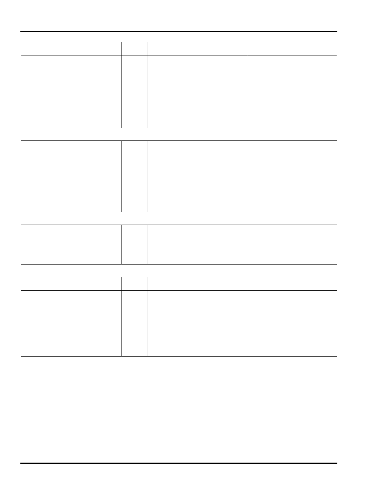
ENGINE & FRAME TORQUE VALUES
• Torque specifications listed below are for important fasteners.
• Others should be tightened to standard torque values listed above.
ENGINE
MAINTENANCE
ITEM Q'TY
Spark plug 4 10 16 (1.6, 12)
Timing hole cap 1 45 18 (1.8, 13) Apply grease to the threads.
Engine oil filter cartridge 1 20 26 (2.7, 19) Apply oil to the threads and
Oil filter boss 1 20 See page 4-16 Apply locking agent.
Engine oil drain bolt 1 12 30 (3.1, 22)
THREAD TORQUE
DIA. (mm) N·m (kgf·m, lbf·ft)
REMARKS
O-ring.
LUBRICATION SYSTEM
ITEM Q'TY
Oil pump assembly bolt 3 6 8 (0.8, 5.9) CT bolt
FUEL SYSTEM (PGM-FI)
ITEM Q'TY
ECT/thermo sensor 1 12 23 (2.3, 17)
Insulator band screw (Throttle
body side)
Insulator band screw (Cylinder
head side)
Fuel rail mounting bolt 4 6 5.1 (0.5, 3.8)
COOLING SYSTEM
ITEM Q'TY
Coolant drain bolt 1 6 12 (1.2, 9) CT bolt
Water pump assembly bolt 2 6 12 (1.2, 9) CT bolt
ENGINE REMOVAL/INSTALLATION
ITEM Q'TY
Drive sprocket bolt 1 10 54 (5.5, 40)
4 5 See page 6-72
4 5 See page 6-67
THREAD TORQUE
DIA. (mm) N·m (kgf·m, lbf·ft)
THREAD TORQUE
DIA. (mm) N·m (kgf·m, lbf·ft)
THREAD TORQUE
DIA. (mm) N·m (kgf·m, lbf·ft)
THREAD TORQUE
DIA. (mm) N·m (kgf·m, lbf·ft)
REMARKS
REMARKS
REMARKS
REMARKS
1-13
Page 14
GENERAL INFORMATION
CYLINDER HEAD/VALVES
ITEM Q'TY
Cylinder head mounting bolt 10 9 51 (5.2, 38) Apply molybdenum oil solu-
Camshaft holder flange bolt 20 6 12 (1.2, 9)
Cylinder head sealing bolt 2 18 28 (2.9, 21) Apply locking agent.
Cylinder head cover bolt 4 6 10 (1.0, 7)
PAIR reed valve cover bolt 4 6 12 (1.2, 9) Apply locking agent.
Cam sprocket bolt 4 7 20 (2.0, 15) Apply locking agent.
Cam chain tensioner pivot bolt 1 6 10 (1.0, 7) Apply locking agent.
Cam chain guide torx bolt 1 6 12 (1.2, 9) Apply locking agent.
Exhaust pipe stud bolt 8 8 See page 3-13
CLUTCH/STARTER CLUTCH
ITEM Q'TY
Clutch center lock nut 1 25 128 (13.1, 94) Apply oil to the threads and
Clutch spring bolt 5 6 12 (1.2, 9)
Oil pump driven sprocket bolt 1 6 15 (1.5, 11) Apply locking agent.
Right crankcase cover rubber
damper set plate bolt
Starter clutch outer mounting bolt 1 10 83 (8.5, 61) Apply oil to the threads and
1 6 12 (1.2, 9) Apply locking agent.
THREAD TORQUE
DIA. (mm) N·m (kgf·m, lbf·ft)
THREAD TORQUE
DIA. (mm) N·m (kgf·m, lbf·ft)
REMARKS
tion to the threads and seating surface.
REMARKS
seating surface.
Stake.
CT bolt
seating surface.
ALTERNATOR
ITEM Q'TY
Stator wire clamp flange bolt 1 6 12 (1.2, 9) CT bolt
Flywheel flange bolt 1 10 103 (10.5, 76) Apply oil to the threads and
Stator mounting socket bolt 4 6 12 (1.2, 9)
TRANSMISSION/GEARSHIFT LINKAGE
ITEM Q'TY
Transmission holder flange bolt 6 8 29 (3.0, 21)
Countershaft bearing set plate
bolt
Mainshaft bearing set plate bolt 3 6 12 (1.2, 9) Apply locking agent.
Shift drum center socket bolt 1 8 23 (2.3, 17) Apply locking agent.
Shift drum stopper arm pivot bolt 1 6 12 (1.2, 9)
Gearshift spindle return spring
pin
Shift drum bearing setting bolt 2 6 12 (1.2, 9) Apply locking agent.
Gearshift cam bolt 1 6 12 (1.2, 9) Apply locking agent.
1 6 12 (1.2, 9) Apply locking agent.
1 8 23 (2.3, 17)
THREAD TORQUE
DIA. (mm) N·m (kgf·m, lbf·ft)
THREAD TORQUE
DIA. (mm) N·m (kgf·m, lbf·ft)
REMARKS
seating surface.
REMARKS
1-14
Page 15
GENERAL INFORMATION
CRANKCASE/CRANKSHAFT/BALANCER/PISTON
ITEM Q'TY
Crankcase 7 mm bolt 12 7 18 (1.8, 13)
8 mm bolt 6 8 24 (2.4, 18)
9 mm bolt (main
journal bolt)
Lower crankcase sealing bolt 1 22 59 (6.0, 44) Apply locking agent.
Lower crankcase socket bolt 1 10 12 (1.2, 9) Apply locking agent.
Lower crankcase sealing bolt 1 20 30 (3.1, 22) Apply locking agent.
Lower crankcase socket bolt 1 8 23 (2.3, 17) Apply locking agent.
Connecting rod bolt (new bolt) 8 8 See page 13-23 Apply oil to the threads and
Connecting rod bolt (retightening) 8 8 See page 13-13 Apply oil to the threads and
ELECTRIC STARTER
ITEM Q'TY
Starter motor terminal nut 1 6 12 (1.2, 9)
LIGHTS/METERS/SWITCHES
ITEM Q'TY
EOP switch 1 PT 1/8 12 (1.2, 9) Apply sealant to the threads.
EOP switch wire terminal bolt 1 4 2 (0.2, 1.5)
Neutral switch 1 10 12 (1.2, 9)
10 9 See page 13-23
THREAD TORQUE
DIA. (mm) N·m (kgf·m, lbf·ft)
THREAD TORQUE
DIA. (mm) N·m (kgf·m, lbf·ft)
THREAD TORQUE
DIA. (mm) N·m (kgf·m, lbf·ft)
REMARKS
seating surface.
seating surface.
REMARKS
REMARKS
1-15
Page 16
GENERAL INFORMATION
0 – 1 mm (0 – 0.04 in)
FRAME
FRAME/BODY PANELS/EXHAUST SYSTEM
ITEM Q'TY
Exhaust pipe joint nut 8 7 20 (2.0, 15)
Side stand pivot bolt 1 10 15 (1.5, 11)
Side stand pivot nut 1 10 39 (4.0, 29)
Grab rail mounting bolt 4 8 27 (2.8, 20)
Front fender mounting bolt (front) 2 6 12 (1.2, 9)
Front fender mounting bolt (rear) 2 6 12 (1.2, 9)
Rearview mirror mounting bolt 4 6 14 (1.4, 10)
MAINTENANCE
ITEM Q'TY
Drive chain adjuster lock nut 2 8 21 (2.1, 15)
FUEL SYSTEM (PGM-FI)
ITEM Q'TY
Fuel tank rear mounting nut 1 6 12 (1.2, 9)
Fuel filler cap mounting bolt 3 4 1.8 (0.2, 1.3)
Fuel feed hose banjo bolt 1 12 22 (2.2, 16)
Fuel pump mounting nut 6 6 12 (1.2, 9) See page 6-56
O
2 sensor 1 18 44 (4.5, 32)
THREAD TORQUE
DIA. (mm) N·m (kgf·m, lbf·ft)
THREAD TORQUE
DIA. (mm) N·m (kgf·m, lbf·ft)
THREAD TORQUE
DIA. (mm) N·m (kgf·m, lbf·ft)
REMARKS
REMARKS
REMARKS
COOLING SYSTEM
ITEM Q'TY
Cooling fan nut 1 5 2.7 (0.3, 2.0)
Fan motor nut 3 5 5.1 (0.5, 3.8) Apply locking agent.
Fan motor bracket mounting bolt 3 6 8.4 (0.9, 6.2)
Radiator hose band:
THREAD TORQUE
DIA. (mm) N·m (kgf·m, lbf·ft)
REMARKS
1-16
Page 17
GENERAL INFORMATION
ENGINE REMOVAL/INSTALLATION
ITEM Q'TY
Front engine hanger bolt 2 12 60 (6.1, 44)
Rear engine hanger nut (upper) 1 12 60 (6.1, 44)
Rear engine hanger nut (lower) 1 12 60 (6.1, 44)
Swingarm pivot bracket nut 2 12 69 (7.0, 51)
Gearshift arm pinch bolt 1 6 10 (1.0, 7)
CLUTCH/STARTER CLUTCH
ITEM Q'TY
Clutch lever pivot bolt 1 6 1 (0.1, 0.7) Apply silicone grease to the
Clutch lever pivot nut 1 6 5.9 (0.6, 4.4)
Clutch master cylinder holder bolt 2 6 12 (1.2, 9)
Clutch master cylinder reservoir
cap screw
Clutch switch mounting screw 1 4 1.2 (0.1, 0.9)
Clutch hose oil bolt 2 10 34 (3.5, 25)
FRONT WHEEL/SUSPENSION/STEERING
ITEM Q'TY
Steering stem adjusting lock nut 1 26 See page 14-34
Steering stem adjusting nut 1 26 25 (2.5, 18) Apply oil to the threads.
Steering stem nut 1 24 103 (10.5, 76)
Bottom bridge pinch bolt 2 10 39 (4.0, 29)
Top bridge pinch bolt 2 8 22 (2.2, 16)
Fork cap 2 37 22 (2.2, 16)
Fork cap lock nut 210 19.6 (2.0, 14)
Fork center bolt 2 8 20 (2.0, 15) Apply locking agent.
Front axle pinch bolt 2 8 22 (2.2, 16)
Front axle bolt 1 14 59 (6.0, 44)
Front brake disc bolt 12 6 20 (2.0, 15) ALOC bolt
Front pulser ring mounting bolt
(CBF1000A)
2 4 1.5 (0.2, 1.1)
3 5 7 (0.7, 5.2) ALOC bolt
THREAD TORQUE
DIA. (mm) N·m (kgf·m, lbf·ft)
THREAD TORQUE
DIA. (mm) N·m (kgf·m, lbf·ft)
THREAD TORQUE
DIA. (mm) N·m (kgf·m, lbf·ft)
REMARKS
REMARKS
sliding surface.
REMARKS
REAR WHEEL/SUSPENSION
ITEM Q'TY
Drive chain case mounting bolt 2 6 12 (1.2, 9)
Rear axle nut 1 18 98 (10.0, 72) U-nut
Rear brake disc bolt 4 8 42 (4.3, 31) ALOC bolt
Driven sprocket nut 5 12 108 (11.0, 80)
Shock absorber mounting nut 2 10 42 (4.3, 31) U-nut
Shock arm nut 2 10 42 (4.3, 31) U-nut
Shock link-to-frame nut 1 10 42 (4.3, 31) U-nut
Swingarm pivot nut 1 18 98 (10.0, 72) U-nut
Drive chain slider screw 2 5 6 (0.6, 4.4)
Rear pulse ring mounting bolt
(CBF1000A)
Gearshift pedal pivot bolt 1 8 27 (2.8, 20)
4 5 7 (0.7, 5.2) ALOC bolt
THREAD TORQUE
DIA. (mm) N·m (kgf·m, lbf·ft)
REMARKS
1-17
Page 18
GENERAL INFORMATION
HYDRAULIC BRAKE
ITEM Q'TY
Brake hose oil bolt
CBF1000A: 6 10 34 (3.5, 25)
CBF1000: 5 10 34 (3.5, 25)
Front brake caliper mounting bolt 4 8 30 (3.1, 22) ALOC bolt
Caliper bleed valve
CBF1000A: 5 8 5.4 (0.6, 4.0)
CBF1000: 3 8 5.4 (0.6, 4.0)
Brake pad pin 3 10 17 (1.7, 13)
Pad pin plug (CBF1000) 2 10 2.5 (0.3, 1.8)
Front brake caliper slide pin
CBF1000A: 2 10 22 (2.2, 16) Apply locking agent.
CBF1000: 2 8 22 (2.2, 16) Apply locking agent.
Front brake caliper bracket pin
CBF1000A: 2 10 12 (1.2, 9)
CBF1000: 2 8 12 (1.2, 9)
Rear brake caliper slide pin 1 12 27 (2.8, 20)
Rear brake caliper bracket pin
(CBF1000A)
Rear brake caliper bolt (CBF1000) 1 8 22 (2.2, 16)
Front master cylinder holder bolt 2 6 12 (1.2, 9)
Front master cylinder reservoir
cap screw
Brake lever pivot bolt 1 6 1 (0.1, 0.7) Apply silicone grease to the
Brake lever pivot nut 1 6 5.9 (0.6, 4.4)
Front brake light switch screw 1 4 1.2 (0.1, 0.9)
Rear master cylinder mounting
bolt
Rear master cylinder reservoir
hose joint screw
Rear master cylinder push rod
lock nut
Rear master cylinder reservoir
mounting bolt
Front brake hose clamp bolt
CB F10 0 0A: 4 6 10 (1.0, 7)
CBF1000: 1 6 10 (1.0, 7)
Front brake hose stay mounting
bolt (CBF1000A)
Rear brake hose guide screw 2 5 4.2 (0.4, 3.1)
1 8 12 (1.2, 9) Apply locking agent.
2 4 1. 5 ( 0 . 2, 1. 1)
2 6 12 (1.2, 9)
1 4 1.5 (0.2, 1.1) Apply locking agent.
1 8 17 (1.7, 13)
1 6 10 (1.0, 7)
1 6 10 (1.0, 7)
THREAD TORQUE
DIA. (mm) N·m (kgf·m, lbf·ft)
REMARKS
sliding surface.
ABS (Anti-lock Brake System)
ITEM Q'TY
ABS modulator lower mounting
bolt
ABS modulator left mounting bolt 1 6 10 (1.0, 7)
Rear brake pipe stay bolt 1 6 12 (1.2, 9)
Front brake hose joint bolt 2 6 10 (1.0, 7)
Front wheel speed sensor mounting bolt
Rear wheel speed sensor mounting bolt
Speed sensor wire clamp bolt 2 6 10 (1.0, 7) ALOC bolt
Brake pipe joint nut 12 10 17 (1.7, 13) Apply brake fluid to the
Proportional control valve mounting bolt
2 6 12 (1.2, 9) ALOC bolt
2 6 10 (1.0, 7)
2 6 10 (1.0, 7)
2 6 12 (1.2, 9)
THREAD TORQUE
DIA. (mm) N·m (kgf·m, lbf·ft)
REMARKS
threads.
1-18
Page 19
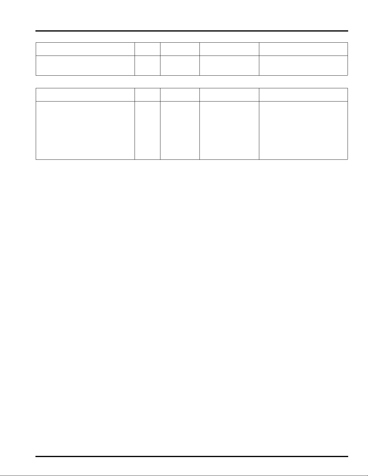
GENERAL INFORMATION
LIGHTS/METERS/SWITCHES
ITEM Q'TY
Ignition switch mounting bolt 2 8 25 (2.5, 18) One-way bolt
License light mounting nut 2 5 1.8 (0.2, 1.3)
Horn mounting bolt 1 8 32 (3.3, 24)
OTHERS
ITEM Q'TY
Footpeg holder mounting bolt 4 8 27 (2.8, 20)
Footpeg lower plate bolt 4 5 5 (0.5, 3.7)
Footpeg holder guard mounting
nut
Gearshift pedal link pivot bolt 1 8 27 (2.8, 20)
License light mounting nut 2 5 1.8 (0.2, 1.3)
Front center cowl stay mounting
nut
Side cowl stay mounting bolt 4 8 32 (3.3, 24)
4 6 12 (1.2, 9)
2 8 27 (2.8, 20)
THREAD TORQUE
DIA. (mm) N·m (kgf·m, lbf·ft)
THREAD TORQUE
DIA. (mm) N·m (kgf·m, lbf·ft)
REMARKS
REMARKS
1-19
Page 20
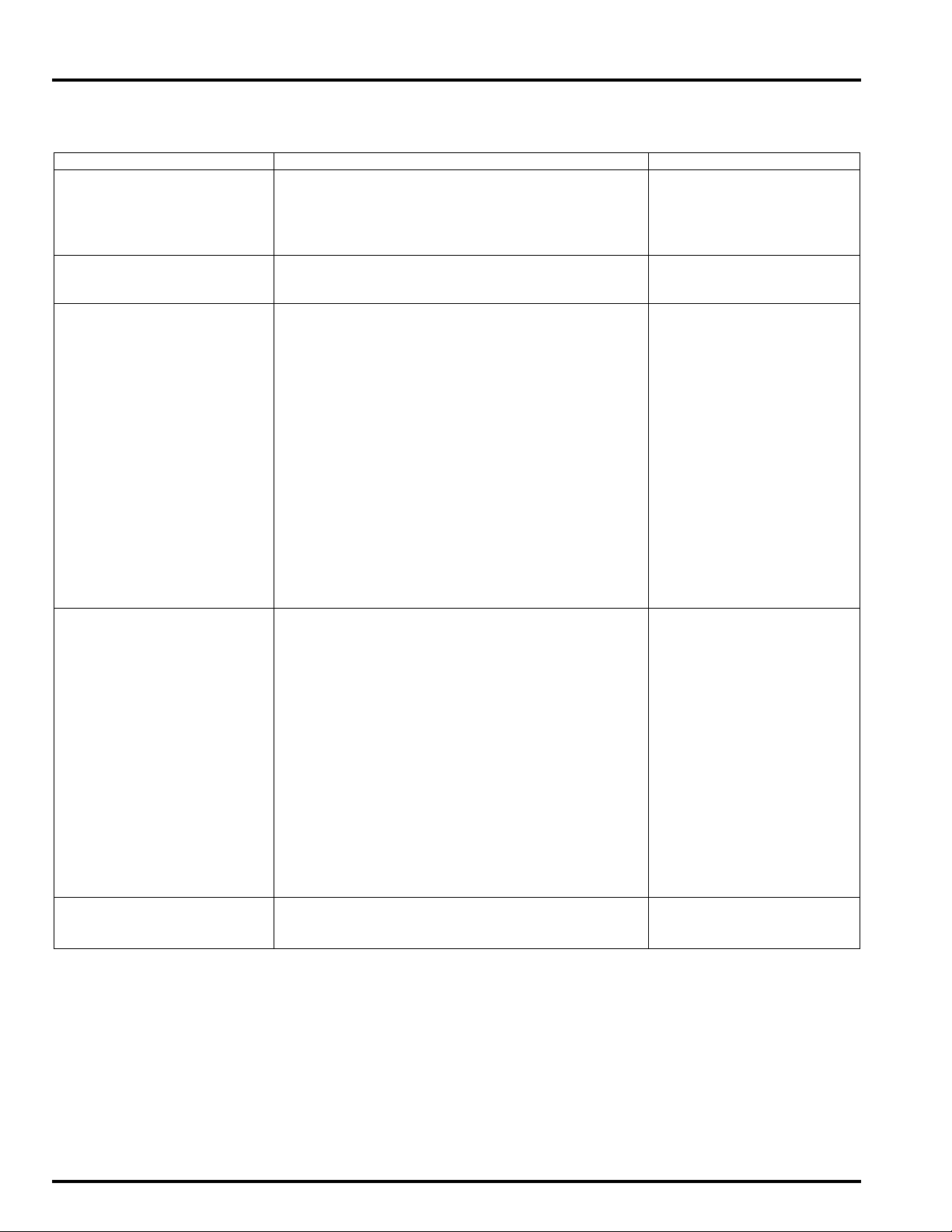
GENERAL INFORMATION
LUBRICATION & SEAL POINTS
ENGINE
MATERIAL LOCATION REMARKS
Liquid sealant
(Three Bond 1207B or equivalent)
Liquid sealant
(Three Bond 5211C or equivalent)
Molybdenum disulfide oil (a
mixture of 1/2 engine oil and
1/2 molybdenum disulfide
grease)
Engine oil Clutch joint piece sliding surface
Multi-purpose grease Timing hole cap threads
Crankcase mating surface See page 13-23
Oil pan mating surface See page 5-7
Right crankcase cover mating surface See page 10-33
Alternator cover mating surface See page 11-5
Oil pressure switch threads See page 21-19
Cylinder head semi-circular cut-out See page 9-31
Main journal bearing surface
Piston pin sliding surface
Connecting rod bearing surface
Connecting rod small end inner surface
Crankshaft thrust surface
Camshaft lobes, journals and thrust surface Do not apply mating sur-
Valve stem (valve guide sliding surface)
Valve lifter outer sliding surface
Clutch outer/primary driven gear sliding surface
Clutch outer guide sliding surface
Oil pump drive sprocket and collar sliding surface
M3/4, C5, C6 shifter gear (shift fork grooves)
Starter reduction gear shaft sliding surface
Starter idle gear shaft sliding surface
Water pump shaft thrust washer sliding surface
Cylinder head mounting bolt threads and seating
surface
Clutch lifter rod outer surface
Piston and piston ring sliding surface
Oil strainer packing whole surface
Clutch disc whole surface
Starter one-way clutch sliding surface
Flywheel bolt threads and seating surface
Clutch center lock nut threads and seating surface
Oil filter cartridge threads and O-ring surface
Camshaft holder bolt threads and seating surface
Starter clutch mounting bolt threads and seating
surface
Connecting rod bolt threads and seating surface
Each gear teeth and rotating surface
Each bearing rolling surface
Each O-ring whole surface
Other rotating area and sliding surface
Balancer damper rubber fitting area
Each oil seal lips
face of the camshaft holder
1-20
Page 21
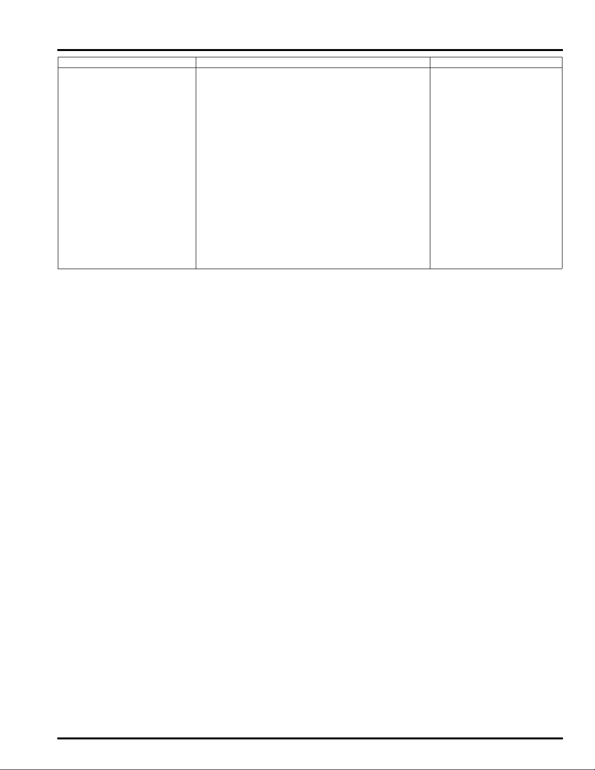
GENERAL INFORMATION
MATERIAL LOCATION REMARKS
Locking agent Gearshift spindle cover bolt threads See page 12-10
Lower crankcase 22 mm sealing bolt threads
Lower crankcase 20 mm sealing bolt threads
Lower crankcase 10 mm sealing bolt threads
Lower crankcase 8 mm sealing bolt threads
Cam chain guide A pivot bolt threads
Cylinder head sealing bolt threads
Cylinder head cover breather joint threads
Oil pump driven sprocket bolt threads Coating width: 6.5 ± 1 mm
Shift drum bearing setting bolt threads Coating width: 6.5 ± 1 mm
Oil filter boss threads (stud side) Coating width: 6.5 ± 1 mm
Right crankcase cover damper rubber plate bolt
threads
Mainshaft/countershaft bearing set plate bolt
threads
Cam sprocket bolt threads Coating width: 6.5 ± 1 mm
Shift drum center bolt threads Coating width: 6.5 ± 1 mm
Cam chain tensioner pivot bolt threads Coating width: 6.5 ± 1 mm
Gearshift cam bolt threads Coating width: 6.5 ± 1 mm
Coating width: 6.5 ± 1 mm
Coating width: 6.5 ± 1 mm
1-21
Page 22

GENERAL INFORMATION
FRAME
MATERIAL LOCATION REMARKS
Multi-purpose grease Side stand pivot sliding area
Center stand pivot sliding area
Throttle cable end
Driver footpeg sliding area
Passenger footpeg sliding area
Gearshift pedal pivot sliding area
Rear brake pedal pivot sliding area
Rear wheel hub O-ring and sleeve (driven flange
contact area)
Front wheel dust seal lips
Rear wheel dust seal lips
Lithium based multi-purpose grease with extreme
pressure (Shell Alvania EP2
or equivalent)
Urea based multi-purpose
grease with extreme pressure agent (example:
EXCELITE EP2 manufactured by KYODO YUSHI,
Japan), Shell Stamina EP2
or equivalent
Molybdenum paste Shock absorber spring adjuster cam sliding area
Engine oil Steering head bearing adjusting nut threads
Cable lubricant Throttle cable A, B casing inside
Honda bond A, Honda hand
grip cement, Cemedine #540
or equivalent
Silicone grease Brake caliper main and sub slide pin sliding surfaces Apply 0.4 g each
DOT 4 brake fluid Master cylinder inner surface
Fork fluid Fork cap O-ring
Locking agent Rear master cylinder reservoir hose joint screw
Swingarm pivot bearings
Swingarm pivot dust seal lips
Shock arm and shock link needle bearings
Shock arm and shock link dust seal lips
Shock absorber pivot dust seal lips
Shock absorber pivot needle bearing
Upper and lower steering head bearing Apply 3 – 5 g each
Steering head dust seal lips
Handlebar grip rubber inside
Brake caliper pin boot inside
Front brake lever pivot
Front brake lever-to-master piston contact area Apply 0.1 g min.
Rear master cylinder push rod-to-master piston con-
tact area
Rear master cylinder push rod boot inside
Brake caliper dust seal
Clutch lever pivot and master piston contact area
Clutch lever joint piece-to-push rod contact area
Brake master pistons and cups
Brake caliper pistons and piston seals
Fork dust seal and oil seal lips
threads
Fork socket bolt threads
Front brake caliper main and sub slide pin bolt
threads
Rear brake caliper sub slide pin bolt threads
Apply 0.1 g min.
1-22
Page 23
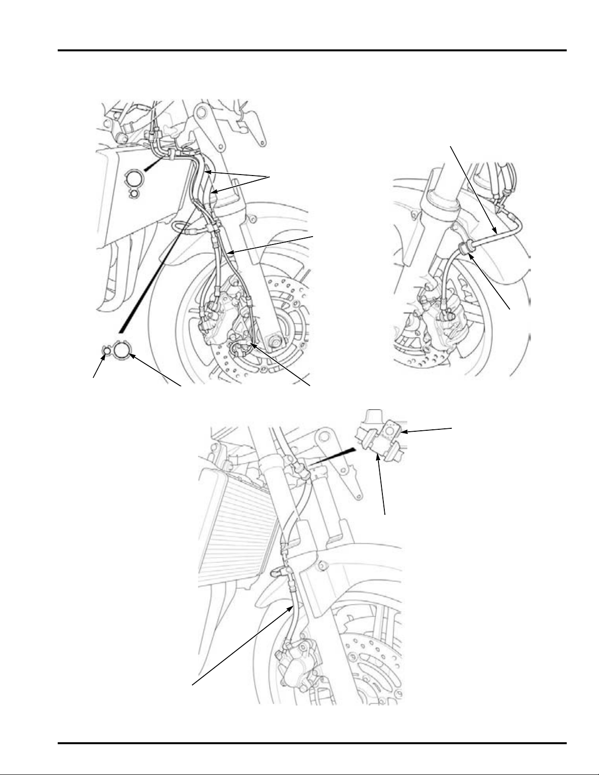
CABLE & HARNESS ROUTING
FRONT WHEEL
SPEED SENSOR
FRONT WHEEL
SPEED SENSOR
WIRE
FRONT BRAKE HOSES
HOSE CLAMP
FRONT BRAKE HOSE
CBF1000A:
SPEED SENSOR
WIRE
BRAKE HOSE
STOPPER
HOSE GUIDE
FRONT BRAKE HOSE
CBF1000:
GENERAL INFORMATION
1-23
Page 24
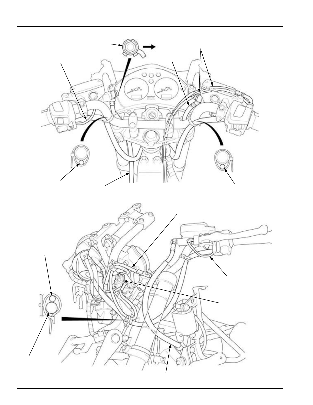
GENERAL INFORMATION
LEFT HANDLEBAR
SWITCH WIRE
CLUTCH HOSE
THROTTLE CABLES
BRAKE HOSE
RIGHT HANDLEBAR
SWITCH WIRE
CLUTCH SWITCH WIRE
CLUTCH HOSE EYELET
Front
LEFT TURN SIGNAL
LIGHT WIRE
CLUTCH SWITCH
WIRE
CLUTCH HOSE
IMMOBILIZER
RECEIVER WIRE
LEFT
HANDLEBAR
SWITCH WIRE
IMMOBILIZER RECEIVER
4P CONNECTOR
1-24
Page 25
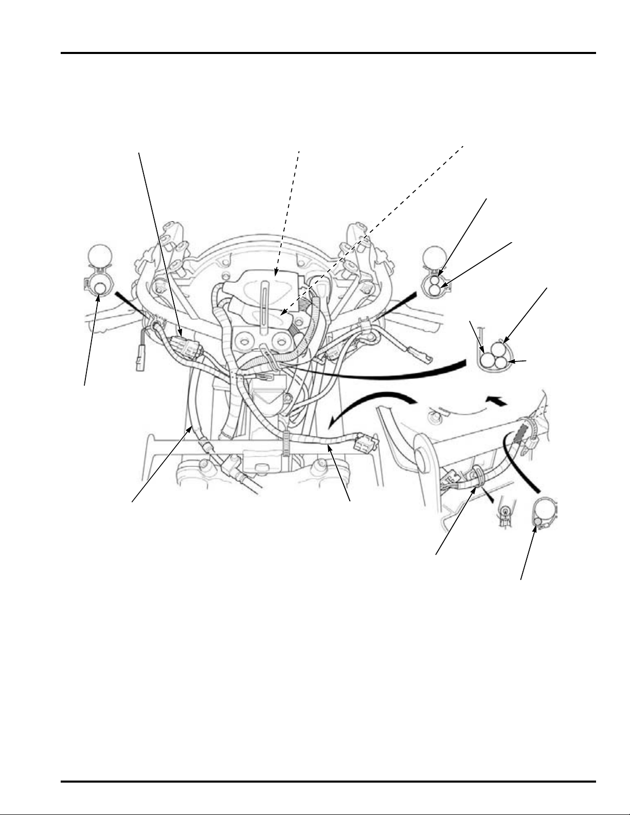
GENERAL INFORMATION
BANK ANGLE SENSOR
3P CONNECTOR
FRONT BRAKE HOSE
HEADLIGHT WIRE
IGNITION
SWITCH WIRE
HANDLEBAR
SWITCH
WIRE
RIGHT HANDLEBAR SWITCH 2P
(Natural), 9P (Brown) CONNECTORS/
IGNITION SWITCH 4P CONNECTOR
LEFT HANDLEBAR SWITCH 6P
(Blue), 4P (Black) CONNECTORS
Front
CLAMP
HEADLIGHT WIRE
MAIN WIRE
HARNESS
LEFT TURN SIGNAL
LIGHT WIRE
IMMOBILIZER
RECEIVER WIRE
20°
RIGHT TURN SIGNAL/
BANK ANGLE
SENSOR WIRE
1-25
Page 26

GENERAL INFORMATION
BANK ANGLE
SENSOR 3P
(Green)
CONNECTOR
THROTTLE
CABLES
IGNITION SWITCH
WIRE
RIGHT HANDLEBAR
SWITCH WIRE
FRONT BRAKE HOSE
MAIN WIRE HARNESS
RIGHT HANDLEBAR
SWITCH WIRE
IGNITION SWITCH
WIRE
1-26
Page 27
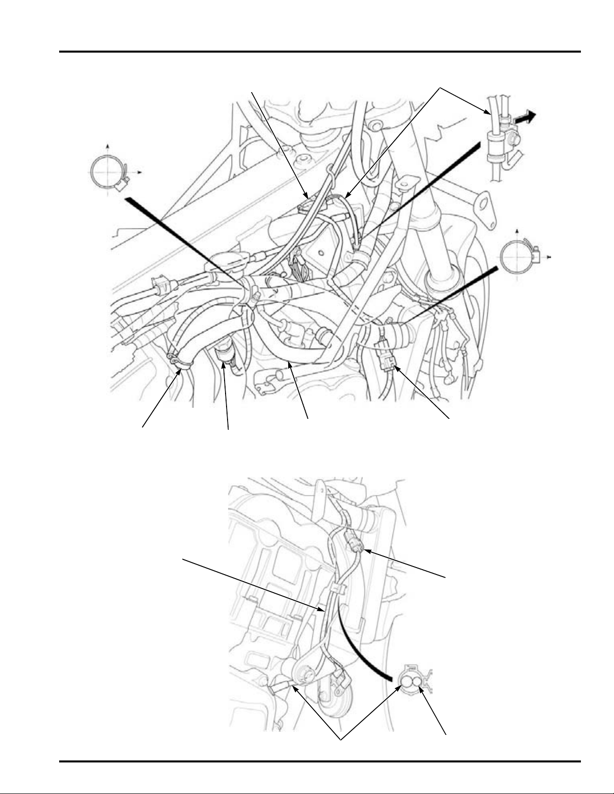
GENERAL INFORMATION
Up
Right
CRANKCASE
BREATHER HOSE
ECT SENSOR 3P
(Gray) CONNECTOR
PAIR AIR HOSE CKP SENSOR 2P (Red)
CONNECTOR
Up
Left
FRONT WHEEL SPEED SENSOR WIRE
(CBF1000A only)
Front
FRONT WHEEL SPEED SENSOR 2P (Blue)
CONNECTOR (CBF1000A only)
HORN WIRE
CKP SENSOR WIRE
HORN WIRE
CKP SENSOR 2P (Red)
CONNECTOR
1-27
Page 28
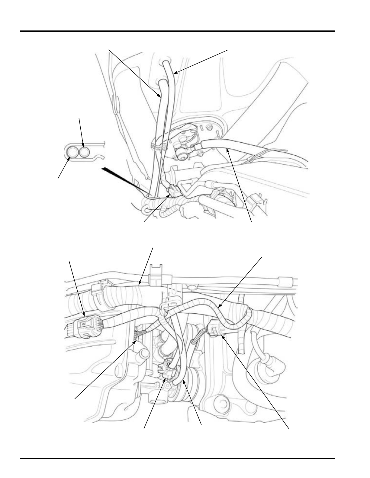
GENERAL INFORMATION
FUEL TANK BREATHER HOSEFUEL TANK DRAIN HOSE
FUEL FEED HOSEFUEL PUMP 3P (Black) CONNECTOR
DRAIN HOSE
BREATHER HOSE
INJECTOR SUB-HARNESS
10P (Black) CONNECTOR
IACV WIRE
MAIN WIRE HARNESS
INTAKE DUCT
DIAPHRAGM
VACUUM HOSE
#4 INJECTOR 2P (Gray)
CONNECTOR
ENGINE SUB-HARNESS
8P CONNECTOR
IACV 4P CONNECTOR
1-28
Page 29
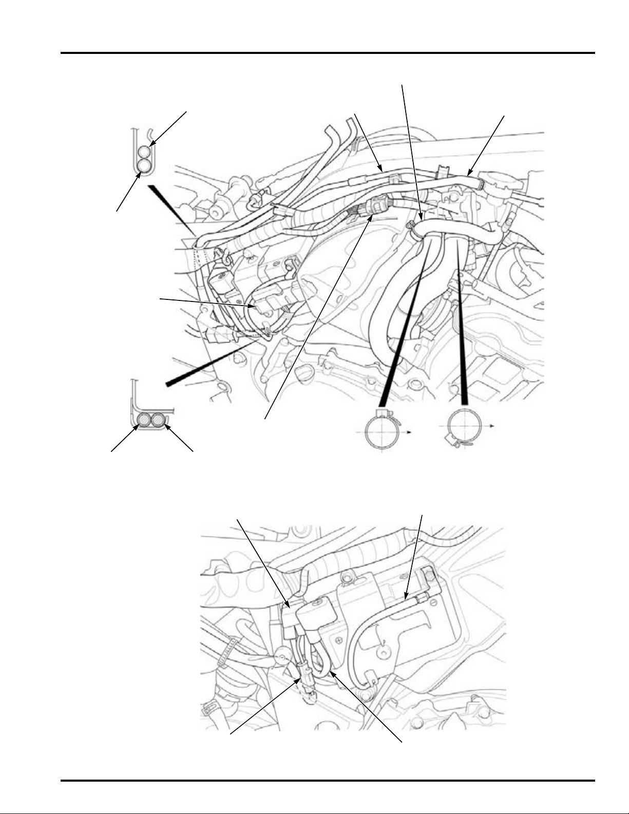
GENERAL INFORMATION
FRONT BRAKE PIPE
(CBF1000A only)
CRANKCASE BREATHER HOSE
THERMOSTAT CASE
SIPHON HOSE
FUEL TANK
DRAIN HOSE
FUEL TANK
BREATHER HOSE
Front
FUSE BOX WIRE
(CBF1000A only)
To main wire
harness
INJECTOR SUB-HARNESS
10P (Black) CONNECTOR
ABS/FI FUSE BOX
(CBF1000A only)
BATTERY NEGATIVE (–) CABLE
BATTERY POSITIVE (+) CABLE
BATTERY LINE
1P CONNECTOR
STARTER RELAY SWITCH
CBF1000:
1-29
Page 30
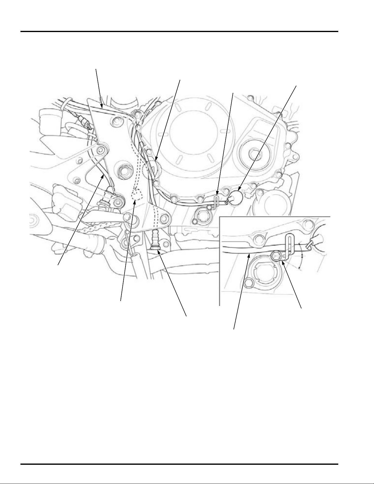
GENERAL INFORMATION
O2 SENSOR WIRE
Hook
EOP SWITCH
O2 SENSOR
NEUTRAL SWITCH
REAR BRAKE LIGHT
SWITCH WIRE
EOP SWITCH WIRE
CLAMP
20°
Bend the clamp
upward
1-30
Page 31
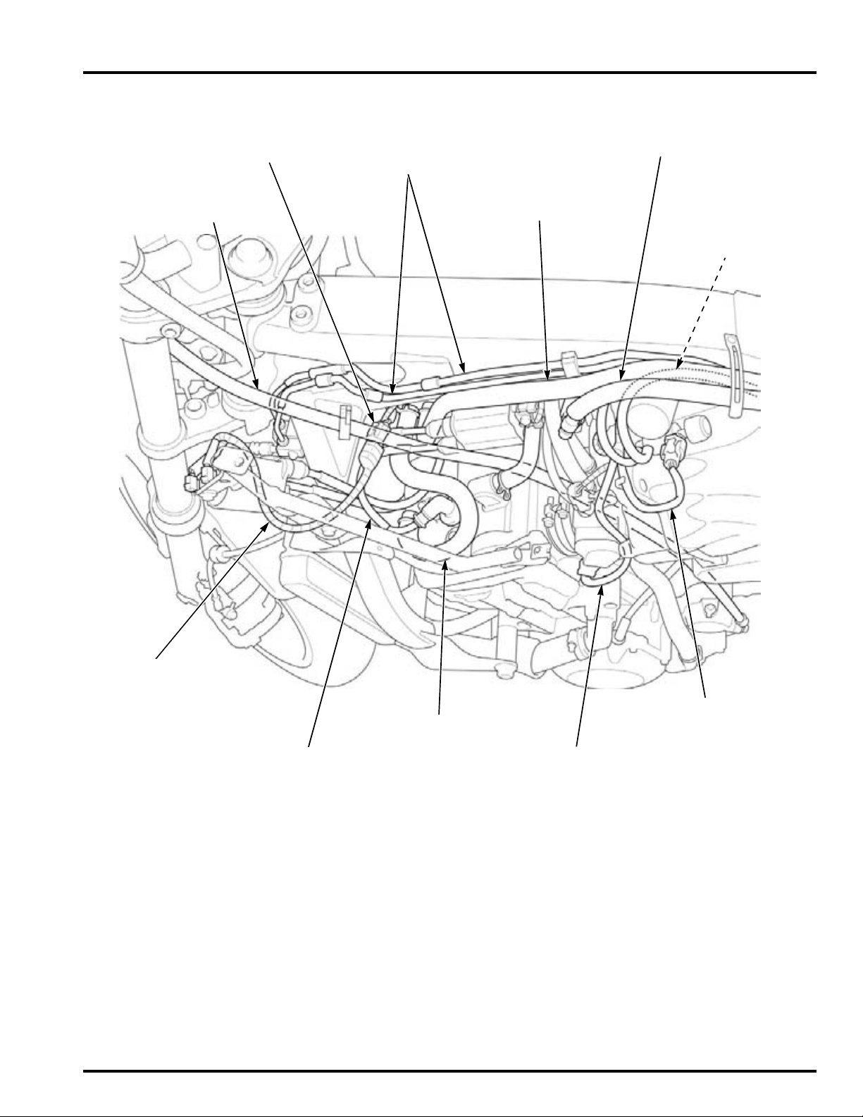
GENERAL INFORMATION
FUEL FEED HOSE
PAIR AIR HOSE
(To air cleaner housing)
CLUTCH HOSE
FRONT BRAKE PIPES
(CBF1000A only)
IGNITION COIL
#2/3 WIRE
SPARK PLUG #1WIRE
PAIR AIR HOSE
TP SENSOR WIRE
INTAKE DUCT CONTROL
VALVE WIRE
INTAKE AIR DUCT
VACUUM HOSE
FAN MOTOR 2P
(Black) CONNECTOR
1-31
Page 32
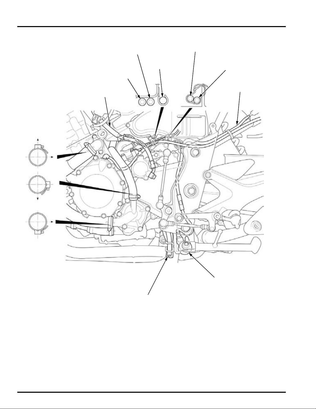
GENERAL INFORMATION
CLUTCH HOSE
Up
Left
Left
Left
SIDE STAND
SWITCH WIRE
GROUND CABLE
STARTER MOTOR CABLE
ALTERNATOR
WIRE
FUEL TANK DRAIN HOSE
FUEL TANK BREATHER HOSE
RADIATOR RESERVE TANK OVERFLOW HOSE
SIDE STAND SWITCH
GROUND CABLE
STARTER
MOTOR CABLE
1-32
Page 33
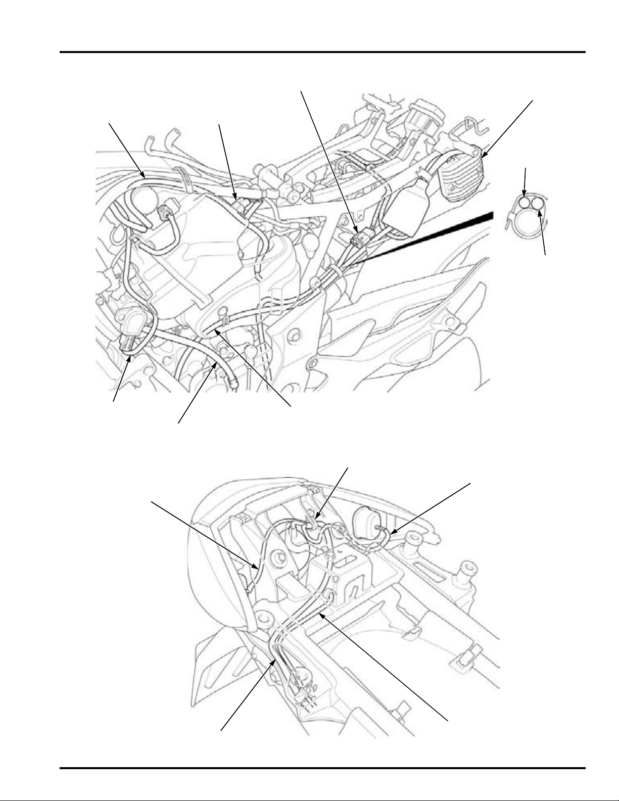
GENERAL INFORMATION
INTAKE DUCT
DIAPHRAGM
VACUUM HOSE
SIDE STAND SWITCH 2P
(Green) CONNECTOR
IAT SENSOR 2P (Gray)
CONNECTOR
REGULATOR/
RECTIFIER
TP SENSOR WIRE
CLUTCH HOSE
ALTERNATOR WIRE
SIDE STAND
SWITCH WIRE
ALTERNATOR
WIRE
RIGHT REAR TURN
SIGNAL LIGHT WIRE
LICENSE LIGHT
WIRE
TAIL/BRAKE LIGHT WIRE
LEFT REAR TURN
SIGNAL LIGHT WIRE
CLAMP
1-33
Page 34
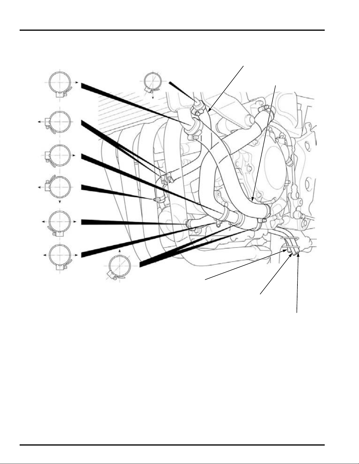
GENERAL INFORMATION
LOWER RADIATOR HOSE
Left
Left
Left
Left
Bottom
Right
Front Rear
Front
Front
Front
Rear
OIL COOLER WATER HOSE
RADIATOR RESERVE
TANK OVERFLOW HOSE
FUEL TANK
BREATHER HOSE
FUEL TANK
DRAIN HOSE
1-34
Page 35
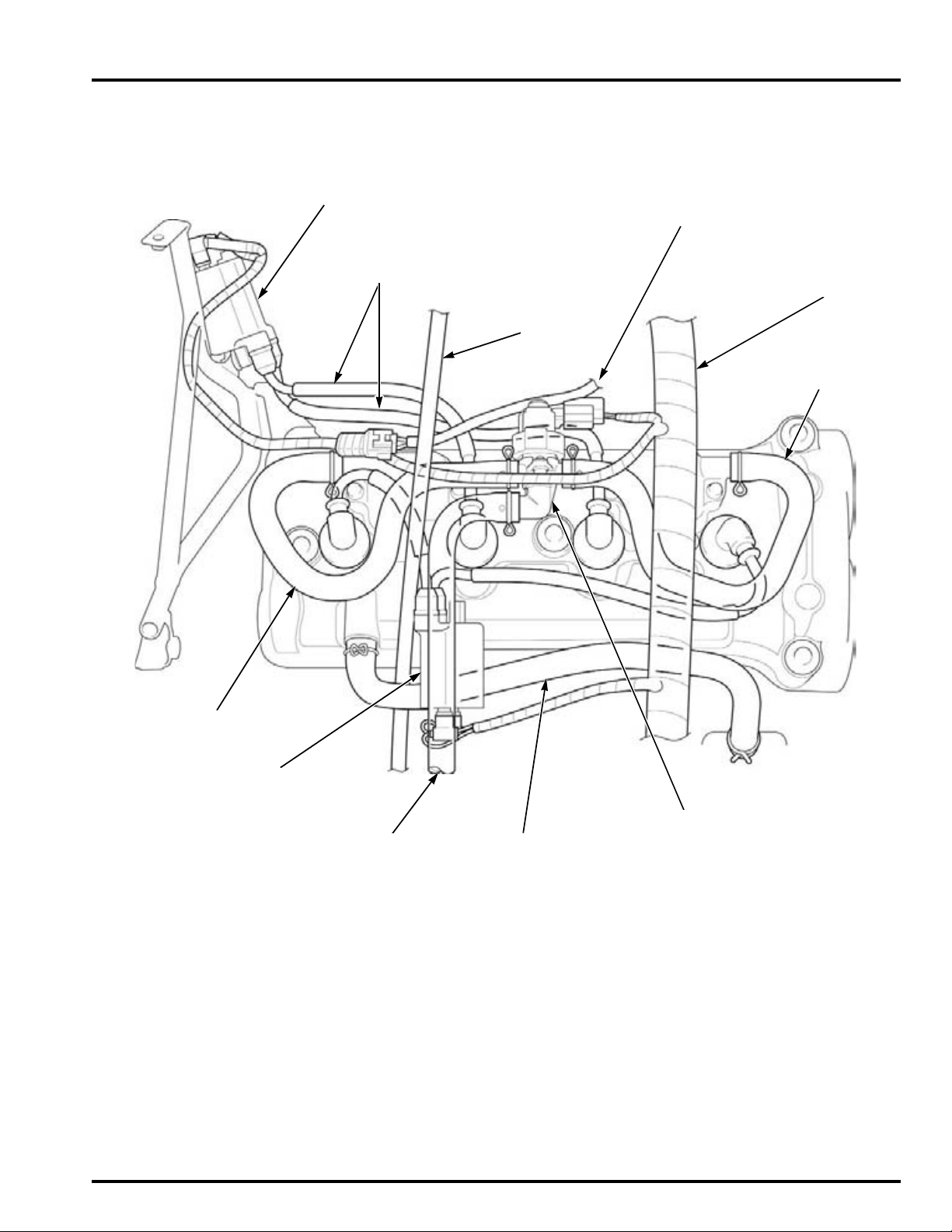
GENERAL INFORMATION
CLUTCH HOSE
IGNITION COIL
#2/#3
To cooling
fan motor
MAIN WIRE
HARNESS
IGNITION COIL
#1/#4
To air cleaner
housing
CRANKCASE
BREATHER HOSE
PAIR CONTROL VALVE
SPARK PLUG WIRES
PAIR AIR HOSE
PAIR AIR HOSE
1-35
Page 36
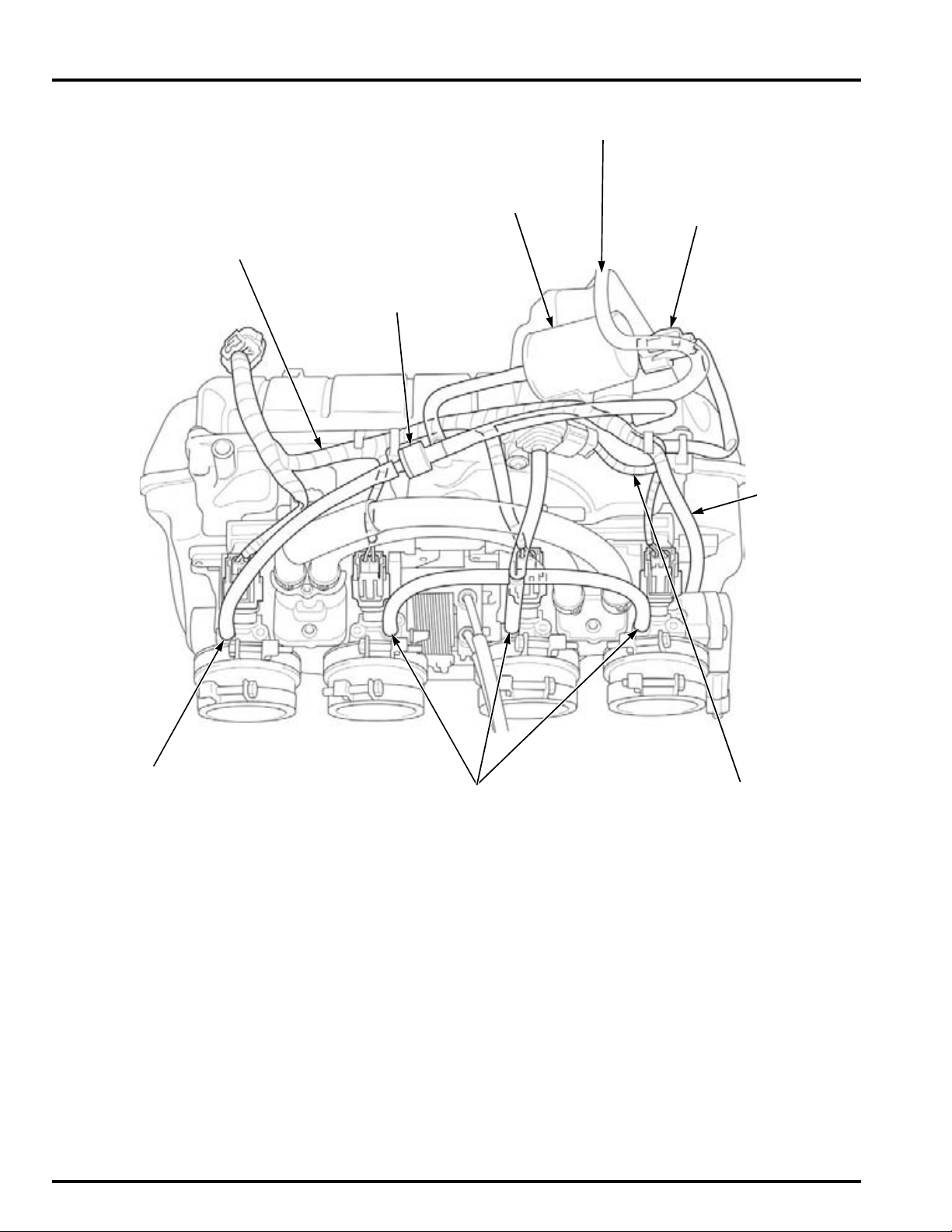
GENERAL INFORMATION
INJECTOR
SUB-HARNESS
INTAKE AIR DUCT CONTROL
VALVE 2P CONNECTOR
INTAKE AIR DUCT
VACUUM HOSE
MAP SENSOR
VACUUM HOSES
TP SENSOR
WIRE
ONE-WAY VALVE
VACUUM CHAMBER
MAP SENSOR
WIRE
To diaphragm
1-36
Page 37
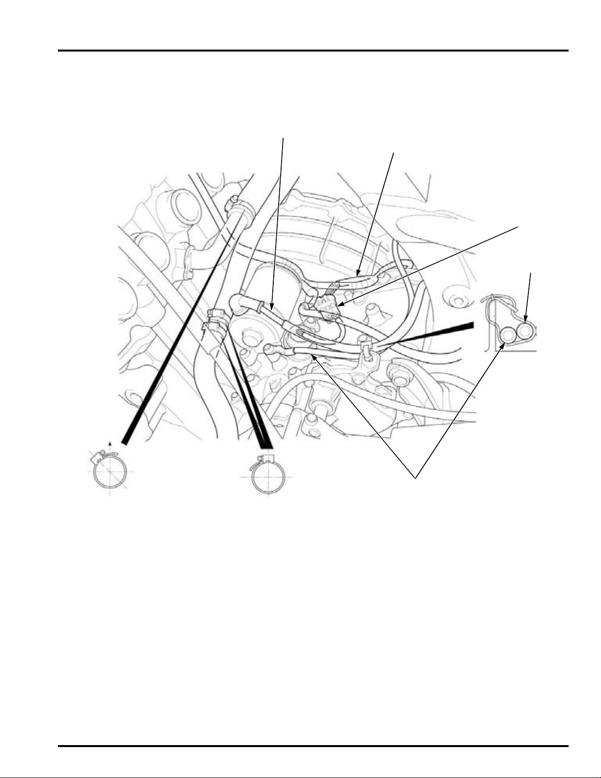
GENERAL INFORMATION
STARTER MOTOR CABLE
VS SENSOR 3P
CONNECTOR
STARTER MOTOR
CABLE
GROUND CABLE
Front
Up
ENGINE SUB-HARNESS
1-37
Page 38
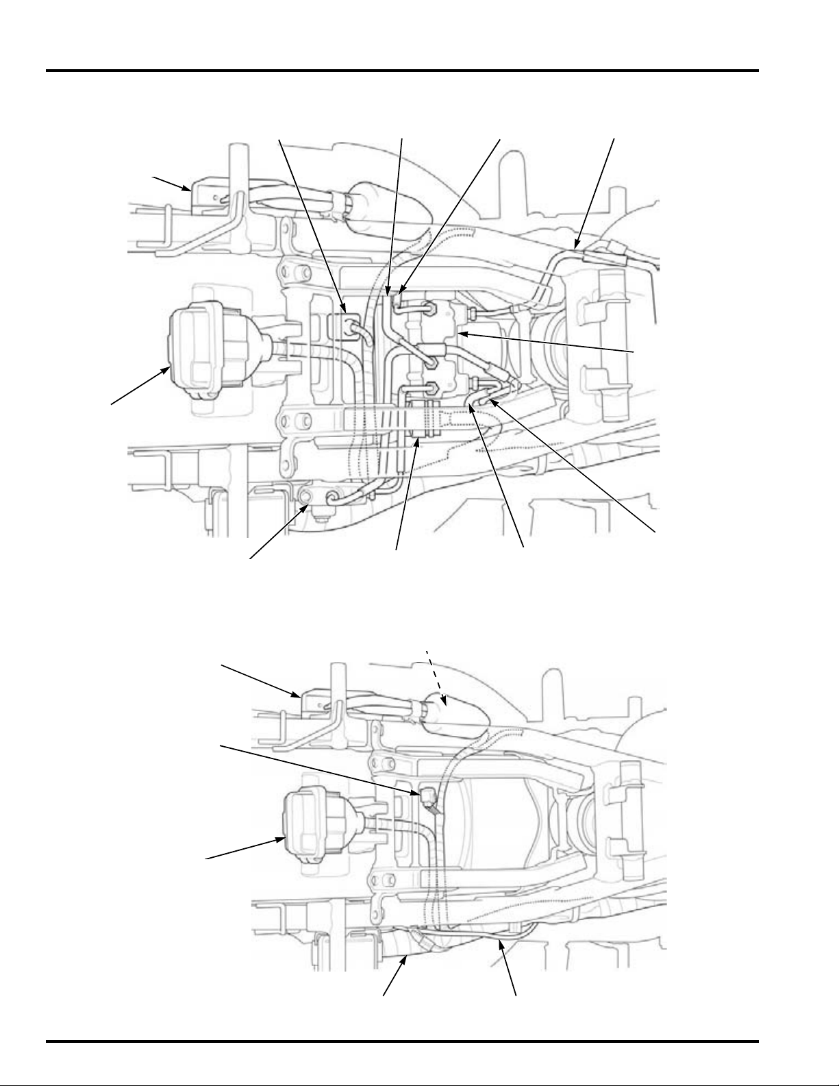
GENERAL INFORMATION
PROPORTIONAL CONTROL VALVE
REGULATOR/
RECTIFIER
CONNECTOR BOOT:
– DLC
– ABS CHECK CONNECTOR
FUSE BOX
ABS MODULATOR
From front master
cylinder
To front brake
calipers
To rear brake
caliper
ABS MODULATOR
25P CONNECTOR
From rear
master cylinder
CBF1000A:
To right front
brake caliper
REGULATOR/
RECTIFIER
FUSE BOX
DLC
O2 SENSOR WIREMAIN WIRE HARNESS
CONNECTOR BOOT:
– ALTERNATOR 3P CONNECTOR
– REGULATOR/RECTIFIER 2P CONNECTOR
CBF1000:
1-38
Page 39
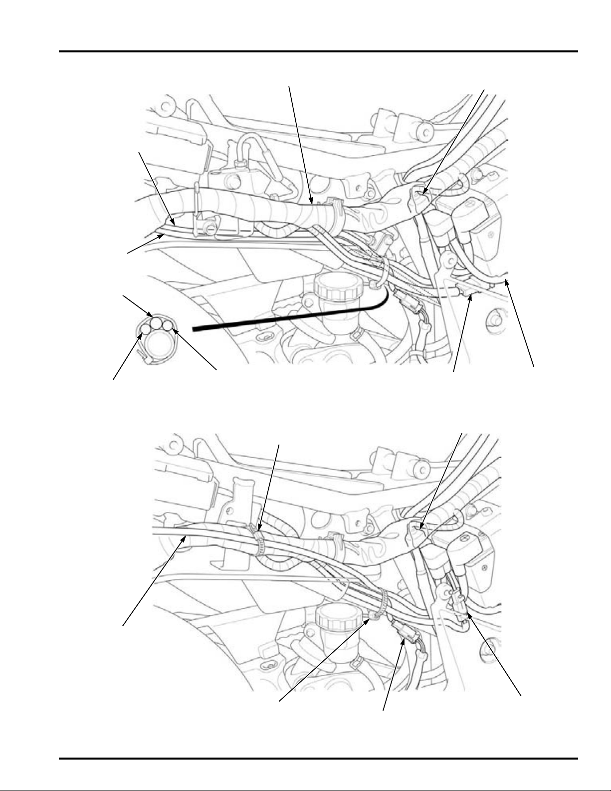
GENERAL INFORMATION
STARTER RELAY SWITCH
4P CONNECTOR
MAIN WIRE HARNESS
FUSE BOX WIRE
REAR BRAKE LIGHT
SWITCH WIRE
O2 SENSOR WIRE
To fuse box
REAR WHEEL SPEED
SENSOR WIRE
ABS/FI FUSE BOX
3P CONNECTOR
O2 SENSOR WIRE
CBF1000A:
WIRE BAND (Bundle with the frame):
– Main wire harness
– O
2 sensor wire
WIRE BAND (Bundle with the frame):
– Rear brake light switch wire
– O
2 sensor wire
– Starter relay switch wire
STARTER RELAY SWITCH
4P CONNECTOR
CBF1000A:
O2 SENSOR WIRE
BATTERY LINE
1P CONNECTOR
REAR BRAKE LIGHT SWITCH
2P CONNECTOR
1-39
Page 40
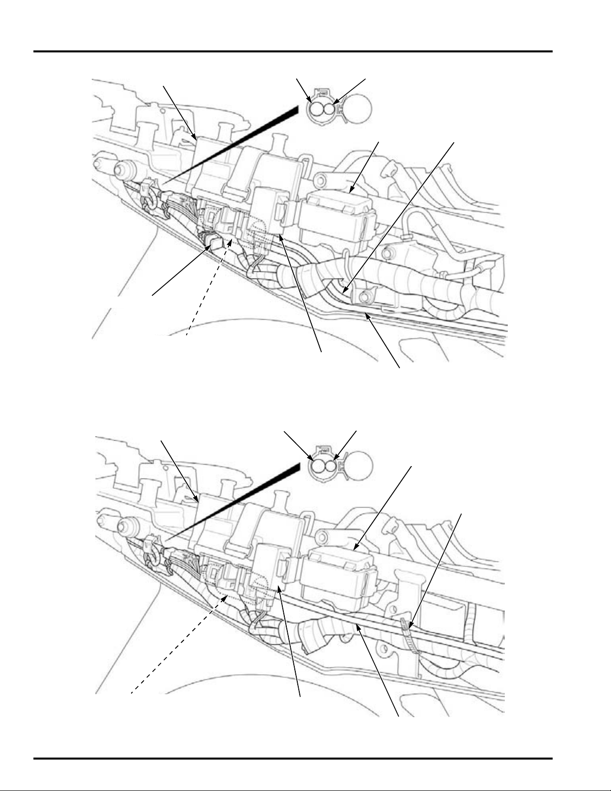
GENERAL INFORMATION
ECM
CONNECTOR BOOT:
– O
2 SENSOR 4P (Natural) CONNECTOR
TURN SIGNAL
LIGHT RELAY
RELAY BOX
TAIL/BRAKE LIGHT WIRE LICENSE LIGHT WIRE
REAR WHEEL SPEED
SENSOR WIRE
O2 SENSOR WIRE
CBF1000A:
– REAR WHEEL SPEED SENSOR
2P (Green) CONNECTOR
OPTION CONNECTOR
ECM
CONNECTOR BOOT:
– O
2 SENSOR 4P (Natural) CONNECTOR
– OPTION CONNECTOR
TURN SIGNAL
LIGHT RELAY
RELAY BOX
TAIL/BRAKE LIGHT WIRE LICENSE LIGHT WIRE
O2 SENSOR WIRE
CBF1000:
WIRE BAND
(Bundle with the frame)
1-40
Page 41
GENERAL INFORMATION
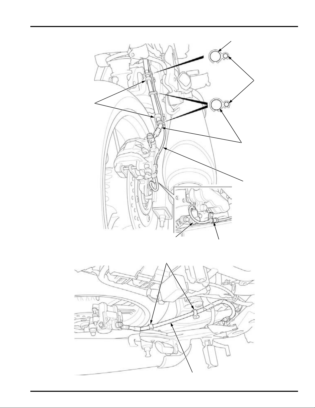
HOSE GUIDES
REAR WHEEL
SPEED SENSOR
SPEED SENSOR
WIRE
REAR BRAKE HOSE
CLAMP
SPEED SENSOR
WIRE
REAR BRAKE HOSE
CBF1000A:
REAR BRAKE HOSE
HOSE GUIDES
CBF1000:
1-41
Page 42
GENERAL INFORMATION
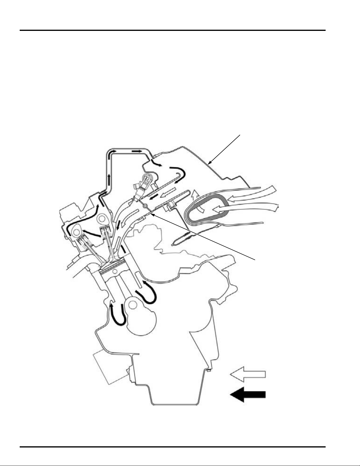
AIR CLEANER HOUSING
THROTTLE BODY
FRESH AIR
BLOW-BY GAS
EMISSION CONTROL SYSTEMS
SOURCE OF EMISSIONS
The combustion process produces carbon monoxide (CO), oxides of nitrogen (NOx) and hydrocarbons (HC). Control of carbon monoxide, oxides of nitrogen and hydrocarbons is very important because, under certain conditions, they react to
form photochemical smog when subject to sunlight. Carbon monoxide does not react in the same way, but it is toxic.
Honda Motor Co., Ltd. utilizes various systems (page 1-43) to reduce carbon monoxide, oxides of nitrogen and hydrocarbons.
CRANKCASE EMISSION CONTROL SYSTEM
The engine is equipped with a closed crankcase system to prevent discharging crankcase emissions into the atmosphere.
Blow-by gas is returned to the combustion chamber through the air cleaner and throttle body.
1-42
Page 43
GENERAL INFORMATION
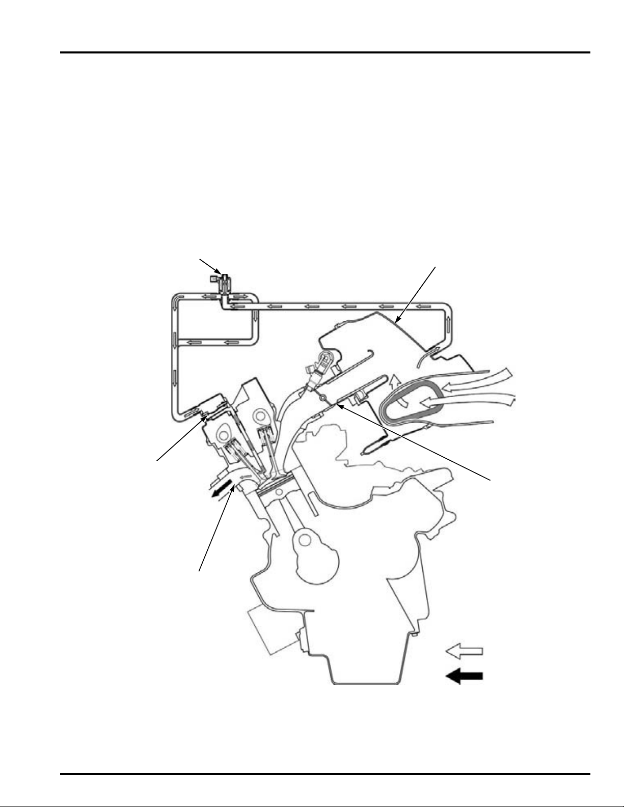
AIR CLEANER HOUSING
THROTTLE BODY
PAIR CONTROL SOLENOID VALVE
PAIR CHECK VALVE
EXHAUST PORT
FRESH AIR
EXHAUST GAS
EXHAUST EMISSION CONTROL SYSTEM
The exhaust emission control system is composed of a pulse secondary air supply system, a three-way catalytic converter
and PGM-FI system.
No adjustment should be made for the exhaust emission control system. The exhaust emission control system is separate
from the crankcase emission control system.
SECONDARY AIR SUPPLY SYSTEM
The pulse secondary air supply system introduces filtered air into the exhaust gases in the exhaust port. Fresh air is drawn
into the exhaust port by the function of the PAIR (Pulse Secondary Air Injection) control valve.
This charge of fresh air promotes burning of the unburned exhaust gases and changes a considerable amount of hydrocarbons and carbon monoxide into relatively harmless carbon dioxide and water vapor.
The reed valve prevents reverse air flow through the system. The PAIR control valve is operated by the solenoid valve. The
solenoid valve is controlled by the PGM-FI unit, and the fresh air passage is opened/closed according the running condition.
No adjustments to the secondary air supply system should be made, although periodic inspection of the components is
recommended.
THREE-WAY CATALYTIC CONVERTER
This motorcycle is equipped with a three-way catalytic converter.
The three-way catalytic converter is in the exhaust system. Through chemical reactions, they convert HC, CO and NOx in
the engine's exhaust to carbon dioxide (CO
No adjustment to these systems should be made although periodic inspection of the components is recommended.
2), nitrogen (N2) and water vapor.
1-43
Page 44
GENERAL INFORMATION
NOISE EMISSION CONTROL SYSTEM
TAMPERING WITH THE NOISE CONTROL SYSTEM IS PROHIBITED: Local law may prohibit the following acts or the causing there of: (1) The removal or rendering inoperative by any person, other than for purposes of maintenance, repair or
replacement, of any device or element of design incorporated into any new vehicle for the purpose of noise control prior to
its sale or delivery to the ultimate purchaser or while it is in use; (2) the use of the vehicle after such device or element of
design has been removed or rendered inoperative by any person.
AMONG THOSE ACTS PRESUMED TO CONSTITUTE TAMPERING ARE THE ACTS LISTED BELOW:
1. Removal of, or puncturing of the muffler, baffles, header pipes or any other component which conducts exhaust gases.
2. Removal of, or puncturing of any part of the intake system.
3. Lack of proper maintenance.
4. Replacing any moving parts of the vehicle, or parts of the exhaust or intake system, with parts other then those specified by the manufacturer.
1-44
Page 45
2. TECHNICAL FEATURES
IACV (Idle Air Control Valve)····················· 2-2 CAMSHAFT POSITION DETECTION WITH
MAP SENSOR············································· 2-4
2
2-1
Page 46
TECHNICAL FEATURES
IACV
DISTRIBUTION HOSES
Idle air flow
TECHNICAL FEATURES
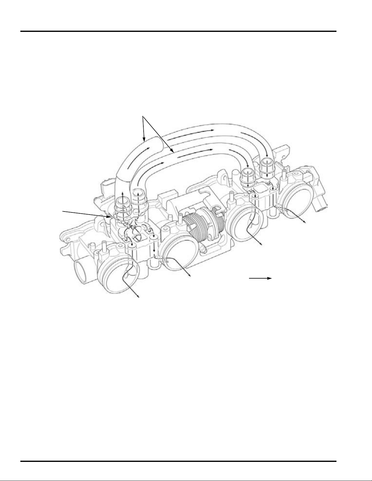
IACV (Idle Air Control Valve)
SUMMARY
This motorcycle adopts an Idle Air Control system for the inline-four engine, this system is composed the IACV and distribution hoses onto the throttle body. The IACV consists of a step motor and a slide valve, and controls the amount of air
bypassed around the closed throttle body. With the ignition switch on, the amount of inlet air is determined from information detected by the ECT sensor. During engine start-up or while maintaining idle (throttle valve closed), the amount of
inlet air is corrected by various sensors' information.
This system eliminates the need for manual idle speed adjustment and the air screw adjustment for the throttle body synchronization.
2-2
Page 47
TECHNICAL FEATURES
VALVE
STEP MOTOR
VALVE
STEP MOTOR
OPERATION
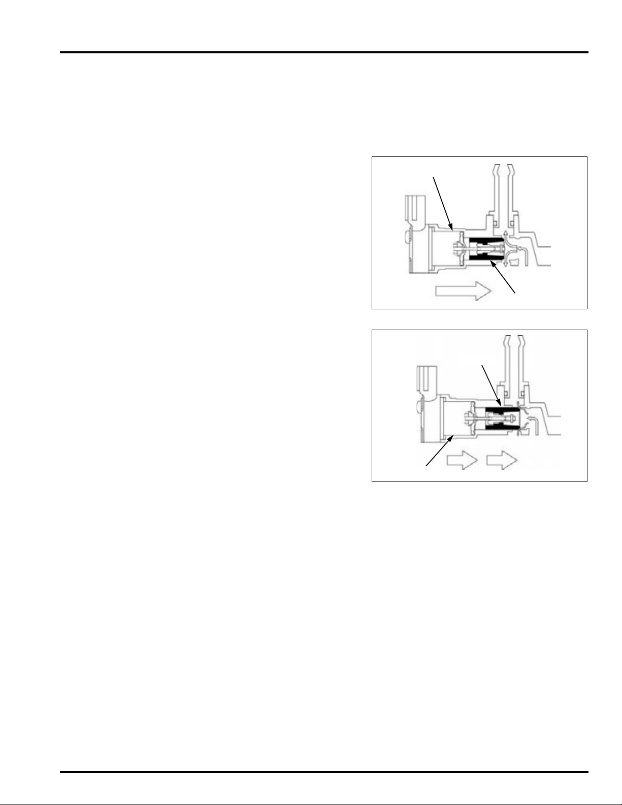
The ECM controls the IACV when engine idling, so the ECM stops to control the IACV operation at closed position in case
that the ECM detects the following condition:
• Throttle valve open
• Neutral switch OFF (in gear) and clutch switch OFF (release clutch lever)
When engine idling, from ignition switch ON to warming up, the ECM control the IACV step motor as following operations:
With the ignition switch ON
When the ignition switch ON, the IACV activates initial function, idle –
open – idle position. There will be a step motor operating sound.
Start the engine – warming up
This optimizes the bypass opening with the throttle valve closed, and
the corrected amount of inlet air passes through allowing proper
engine start up.
After the engine has started, the ECM controls the IACV slide valve
position and adjust the amount of inlet air in response to the engine
coolant temperature.
After warming up – idling
When the ECM denotes the engine warming-up by the engine coolant
temperature, it operates the step motor to move the slide valve to the
closed position. This results in a reduced amount of bypassed air compared to the amount during engine warm-up, which allows proper
engine idle to be maintained.
2-3
Page 48
TECHNICAL FEATURES
CAMSHAFT POSITION DETECTION WITH MAP SENSOR
SUMMARY
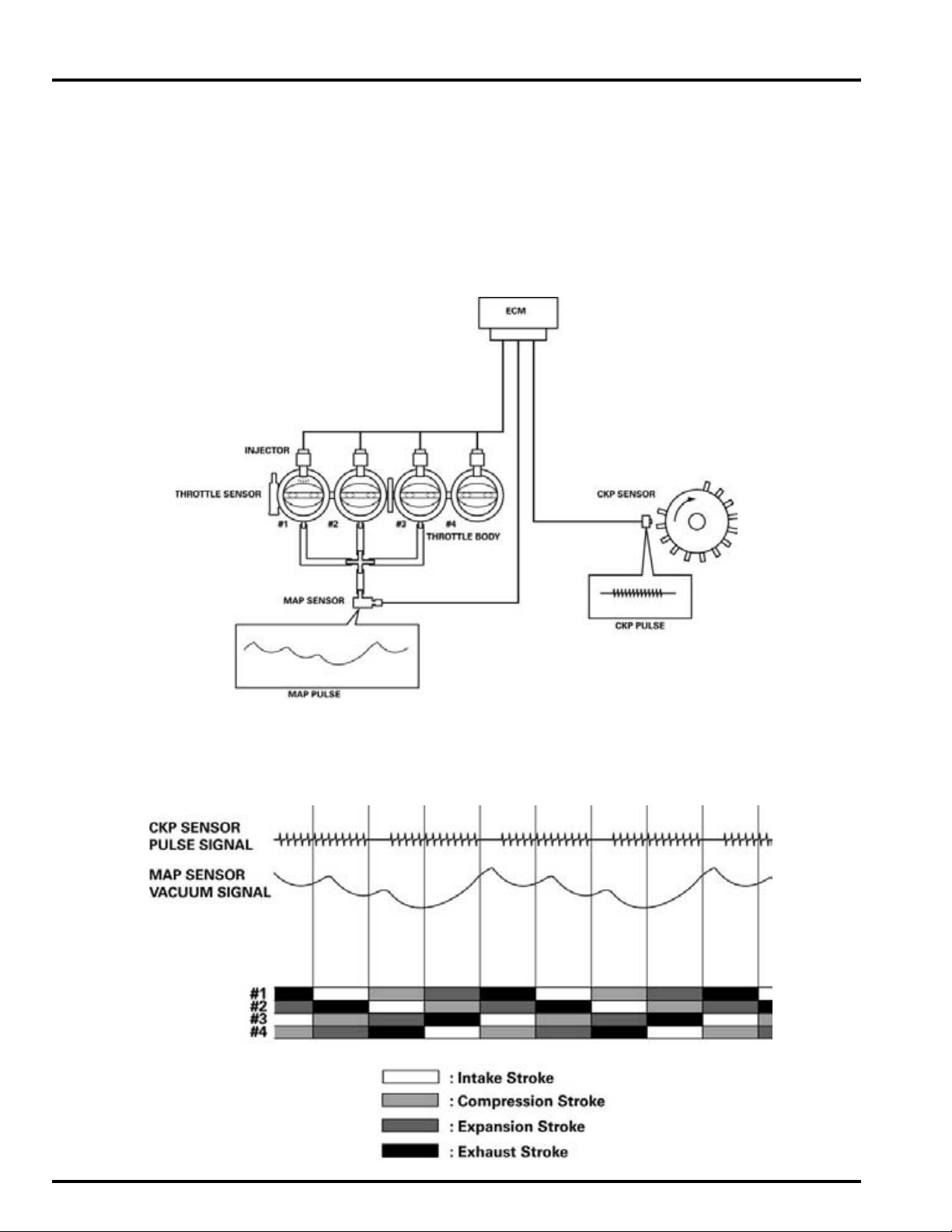
For PGM-FI, it is necessary to detect the stroke position not only of the crankshaft (TDC position) but also of the camshaft
(TDC position in compression stroke). Existing PGM-FI for inline-4 engine, the system uses the CKP sensor and CMP sensor
for the injection timing control. This motorcycle adopts the PGM-FI system that has the new detection system of the camshaft position. This PGM-FI system allows for the camshaft position detection with the MAP sensor and CKP sensor, and
eliminates CMP sensor.
The detection system consists of the crankshaft rotor and CKP sensor for the crankshaft position (TDC position) detection,
and MAP sensor connected to No.1, 2, 3 throttle manifold via vacuum hoses for the camshaft position (TDC position in
compression stroke) detection.
DETECTION SYSTEM
The ECM always monitors the manifold pressure by the MAP sensor signal and figures it. In response to the camshaft position (TDC position in compression stroke), the MAP figure changes its wave profile. The ECM recognizes these wave profile
repetition and combined with the CKP sensor, then detects the camshaft position.
2-4
Page 49
3. FRAME/BODY PANELS/EXHAUST SYSTEM
3
SERVICE INFORMATION ··························· 3-2
TROUBLESHOOTING ································· 3-2
SEAT···························································· 3-3
SEAT BRACKET ·········································· 3-3
RIGHT/LEFT SIDE COVER·························· 3-4
WINDSCREEN············································· 3-4
METER PANEL ············································ 3-5
RIGHT/LEFT FRONT COWLS····················· 3-6
REARVIEW MIRROR··································· 3-6
FRONT CENTER COWL······························ 3-7
REAR COWL ··············································· 3-8
FRONT FENDER ········································· 3-9
REAR FENDER ·········································· 3-10
MUFFLER ·················································· 3-12
EXHAUST PIPE········································· 3-13
MAIN STAND (CBF1000A)······················· 3-15
SIDE STAND ············································· 3-16
3-1
Page 50
FRAME/BODY PANELS/EXHAUST SYSTEM
FRAME/BODY PANELS/EXHAUST SYSTEM
SERVICE INFORMATION
GENERAL
• Work in a well ventilated area. Smoking or allowing flames or sparks in the work area or where gasoline is stored can
cause a fire or explosion.
• This section covers removal and installation of the body panels and exhaust system.
• Serious burns may result if the exhaust system is not allowed to cool before components are removed or serviced.
• Always replace the exhaust pipe gaskets after removing the exhaust pipe from the engine.
• When installing the exhaust system, loosely install all of the exhaust pipe fasteners. Always tighten the exhaust clamps
first, then tighten the mounting fasteners. If you tighten the mounting fasteners first, the exhaust pipe may not seat
properly.
• Always inspect the exhaust system for leaks after installation.
TORQUE VALUES
Exhaust pipe joint nut 20 N·m (2.0 kgf·m, 15 lbf·ft)
Side stand pivot bolt 15 N·m (1.5 kgf·m, 11 lbf·ft)
Side stand pivot nut 39 N·m (4.0 kgf·m, 29 lbf·ft)
Grab rail mounting bolt 27 N·m (2.8 kgf·m, 20 lbf·ft)
Front fender mounting bolt 12 N·m (1.2 kgf·m, 9 lbf·ft)
Rearview mirror mounting bolt 14 N·m (1.4 kgf·m, 10 lbf·ft)
TROUBLESHOOTING
Excessive exhaust noise
• Broken exhaust system
• Exhaust gas leak
Poor performance
• Deformed exhaust system
• Exhaust gas leak
• Clogged muffler
3-2
Page 51
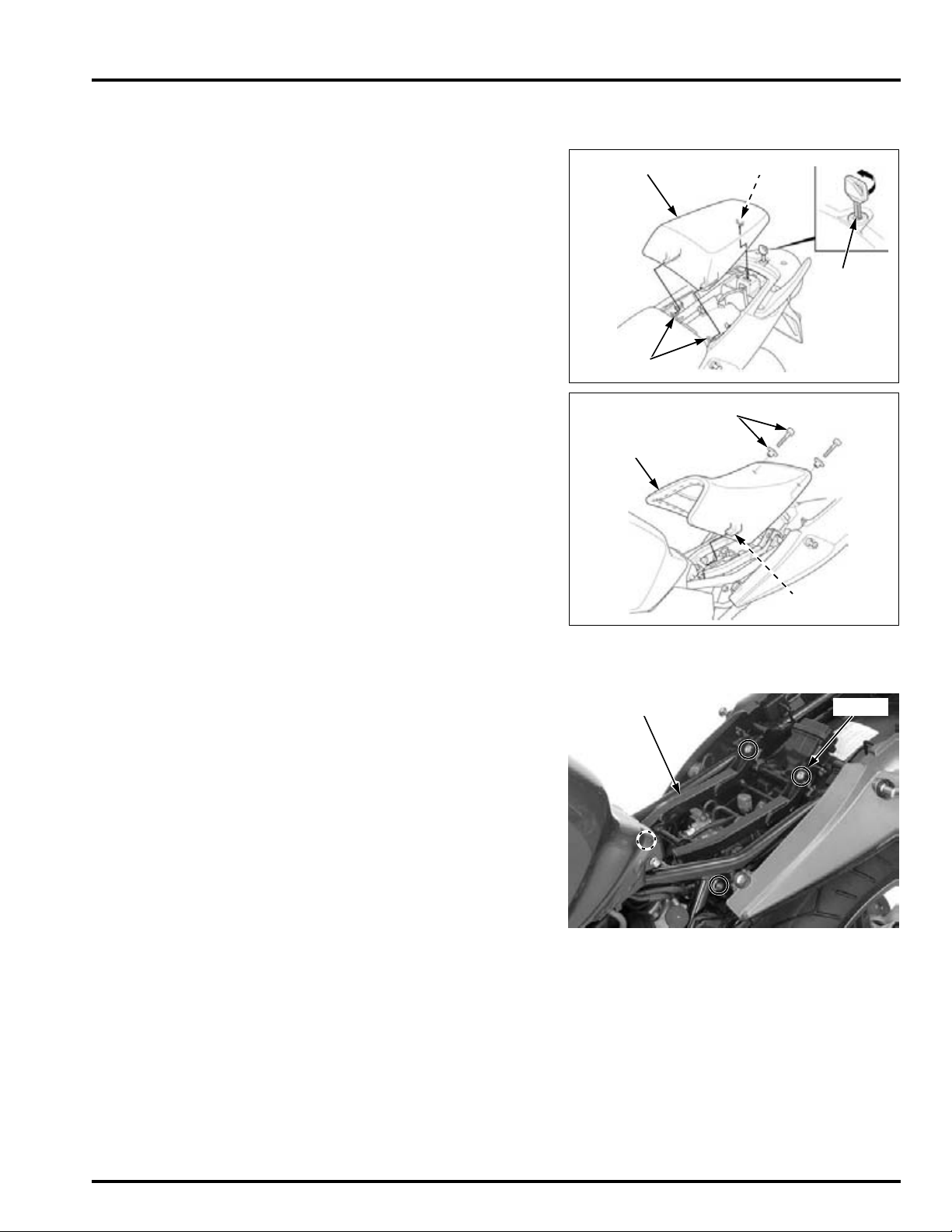
SEAT
REAR SEAT
HOOKS
HOOK
KEY
SOCKET BOLTS/
COLLARS
PRONG
FRONT SEAT
SEAT BRACKET BOLTS
FRAME/BODY PANELS/EXHAUST SYSTEM
REMOVAL/INSTALLATION
Unhook the pillion seat with the ignition key.
Remove the rear seat.
Remove the socket bolts and collars.
Remove the front seat backward while releasing the
seat prong from the seat bracket.
Install the front seat while hooking the prong under
the seat bracket cross pipe.
Install the collars and tighten the socket bolts.
Install the rear seat and push the seat forward, then
down to lock it.
After installation, make sure that the seats are
installed properly by moving them.
SEAT BRACKET
REMOVAL/INSTALLATION
Remove the side socket bolts, rear socket bolts and
seat bracket.
If you wish the seat position upward or downward,
you can choose low or high position.
There are three bolt holes each mounting point.
Middle bolt hole is standard position.
Install the seat bracket.
Install and tighten the side socket bolts (flange) and
rear socket bolts securely.
3-3
Page 52
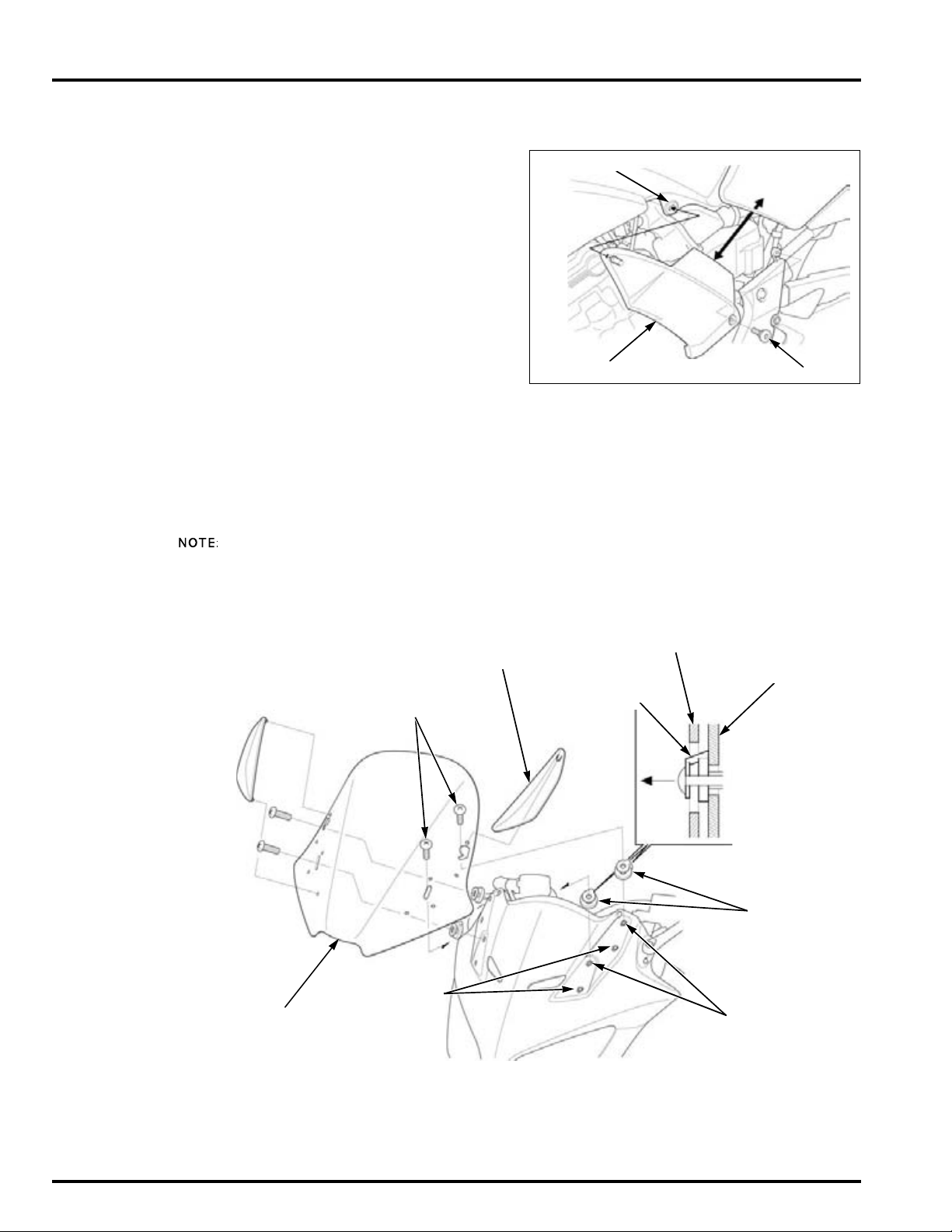
FRAME/BODY PANELS/EXHAUST SYSTEM
GROMMET
SIDE COVER BOLT
COVER
WINDSCREEN
SPACERS
FRONT
CENTER COWL
SCREWS
WINDSCREEN
SPACER
Front
High position
Low position
RIGHT/LEFT SIDE COVER
REMOVAL/INSTALLATION
Remove the side cover bolt.
Release the boss from the fuel tank grommet, then
remove the side cover.
Install the side cover aligning the its boss with the
grommets in the fuel tank.
WINDSCREEN
REMOVAL/INSTALLATION
Be careful not to
damage the
bosses.
Remove the windscreen covers by pulling its
bosses.
Remove the four screws and the windscreen.
Installation is in the reverse order of removal.
• Install the spacer onto the windscreen as shown.
• It is possible to select the windscreen high or low
position.
3-4
Page 53
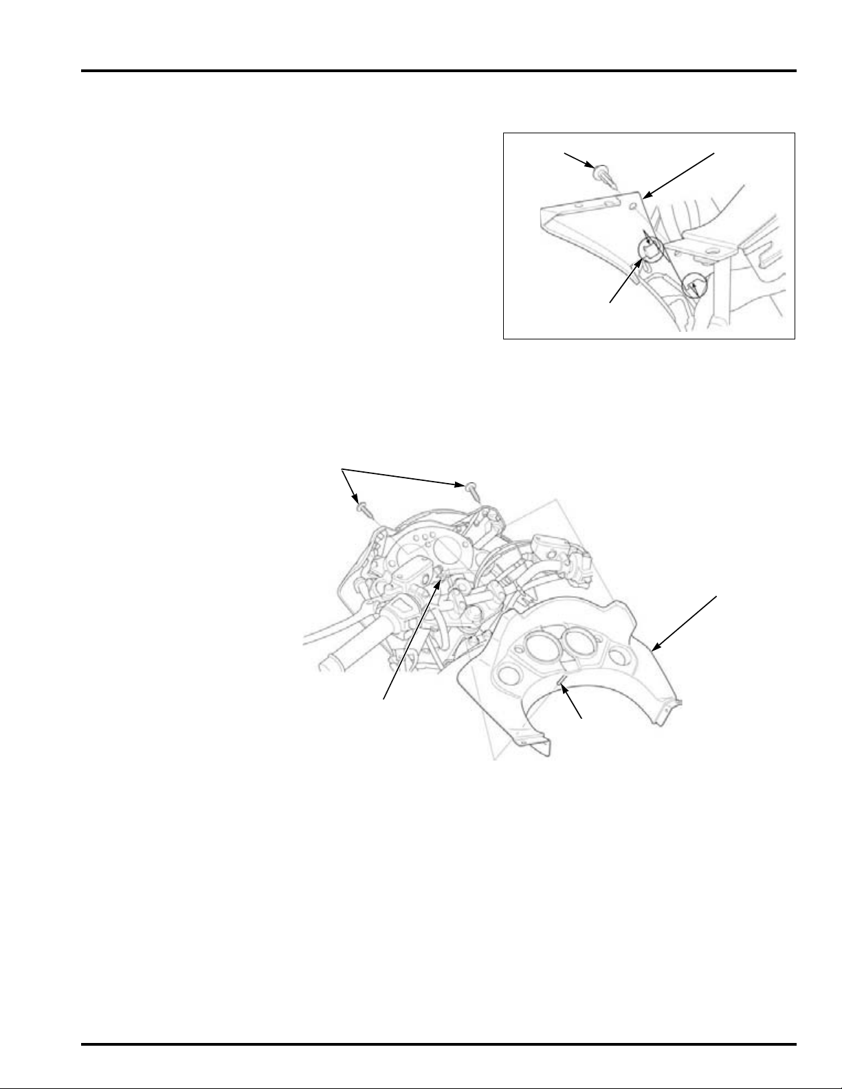
METER PANEL
TRIM CLIP INNER PANEL
TAB
SCREWS
BOSS
METER PANEL
GROMMET
REMOVAL/INSTALLATION
Remove the trim clip.
Unhook the tab of the inner panel from the front
center cowl, then remove the inner panel.
Remove the other side inner panel.
Remove the windscreen (page 3-4).
Remove the two screws.
Pull the boss of the meter panel from the combination meter grommet, then remove the meter panel.
Install the meter panel and inner panels in the
reverse order of removal.
FRAME/BODY PANELS/EXHAUST SYSTEM
3-5
Page 54
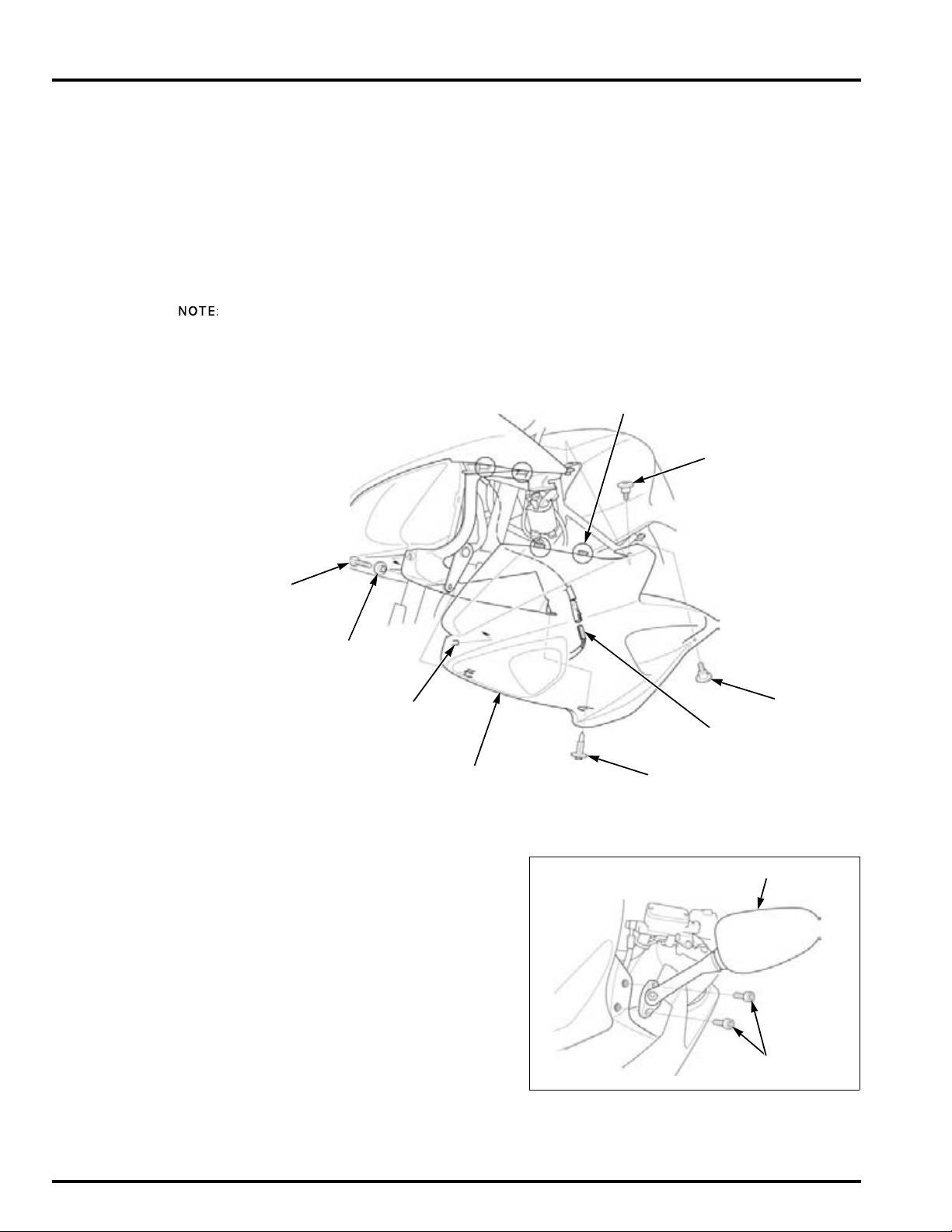
FRAME/BODY PANELS/EXHAUST SYSTEM
BOLT
BOLT
BOSS
RIGHT FRONT COWL
TRIM CLIP
TABS
BOLT
COLLAR
CONNECTOR
SOCKET BOLTS
REARVIEW MIRROR
RIGHT/LEFT FRONT COWLS
REMOVAL/INSTALLATION
Remove the following:
– Trim clip
– Bolt and collar
– Mounting bolts
Unhook the boss and tabs from the front center
cowl, then disconnect the turn signal light wire connector.
Installation is in the reverse order of removal.
The illustration shows the right front cowl removal/
installation. Remove and install the left front cowl in
the same manner.
REARVIEW MIRROR
REMOVAL/INSTALLATION
Remove the socket bolts and rearview mirror.
Installation is in the reverse order of removal.
TORQUE: 14 N·m (1.4 kgf·m, 10 lbf·ft)
3-6
Page 55
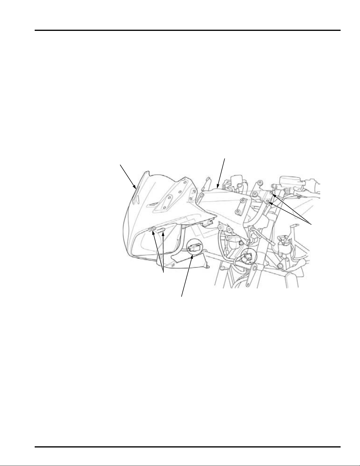
FRONT CENTER COWL
FRONT CENTER COWL
BOSSES
HEADLIGHT CONNECTOR
BOSSES
METER GUARD RUBBER
REMOVAL/INSTALLATION
Remove the following:
– Rearview mirror (page 3-6)
– Meter panel (page 3-5)
– Right and left front cowls (page 3-6)
Release the rearview mirror mounting bosses from
the front center cowl.
Remove the front center cowl by pulling its bosses
from the grommet, then disconnect the headlight
connector.
Remove the meter guard rubber from the front center cowl stay.
Be careful not to
jam the guard
rubber between the
front center cowl
and stay.
Installation is in the reverse order of removal.
FRAME/BODY PANELS/EXHAUST SYSTEM
3-7
Page 56
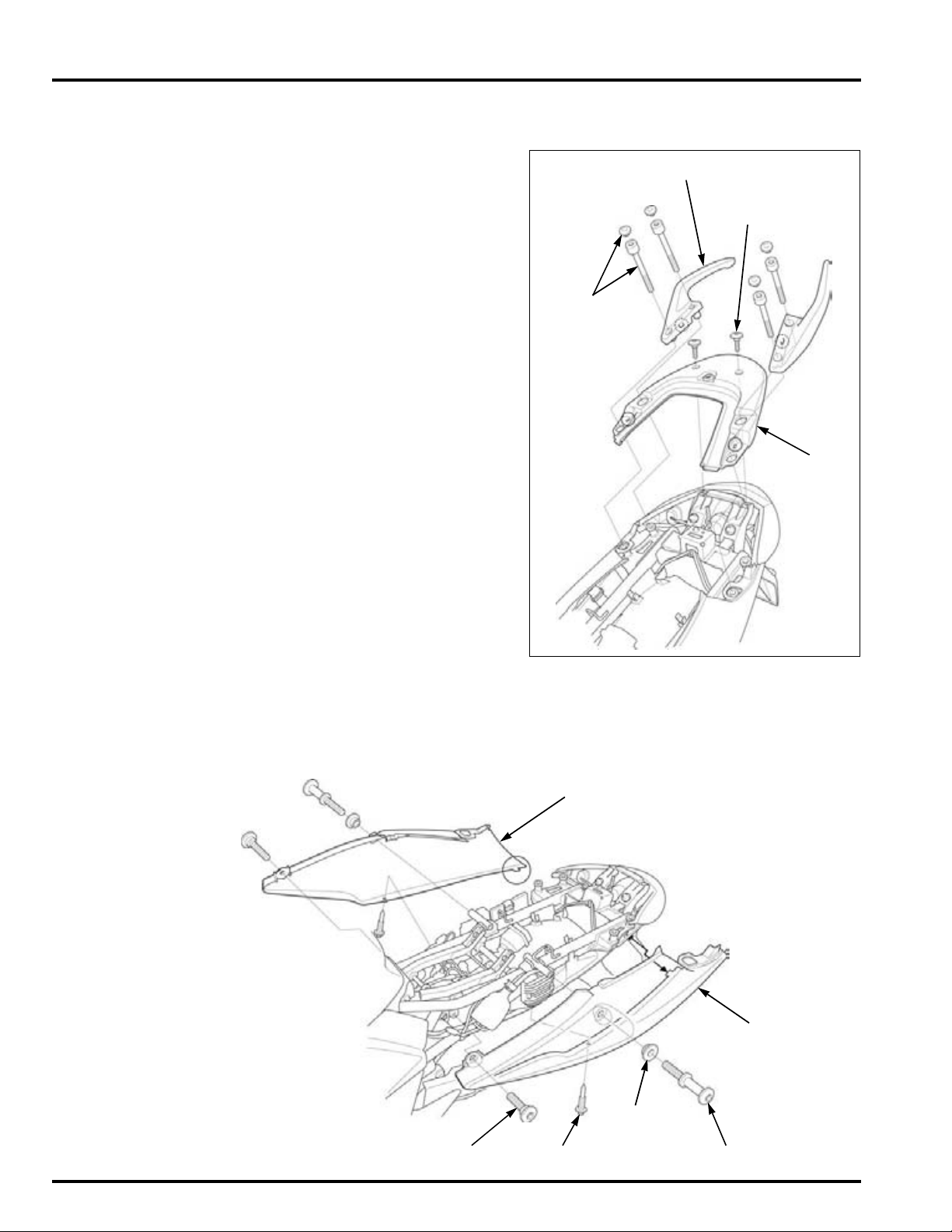
FRAME/BODY PANELS/EXHAUST SYSTEM
BOLT CAPS/
SOCKET
BOLTS
REAR
CENTER
COWL
BOLTS
GRAB RAIL
BOLT
RIGHT REAR COWL
LEFT REAR COWL
HOOK BOLT
COLLAR
TRIM CLIP
Align
REAR COWL
REMOVAL
Remove the seat (page 3-3).
Remove the bolt caps.
Remove the socket bolts and grab rails.
Remove the bolts and rear center cowl.
Remove the trim clip.
Remove the bolt, hook bolt and collar.
Carefully release the tab of the rear cowl, then
remove.
Remove the other side rear cowl in the same manner.
3-8
Page 57
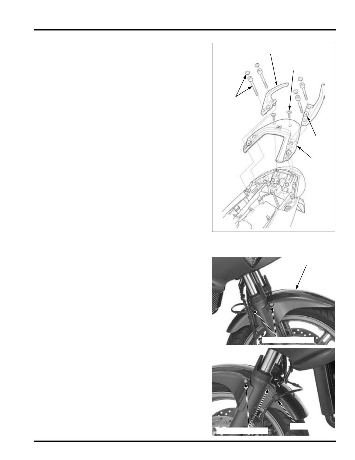
Align the tab on the
BOLT CAPS/
SOCKET
BOLTS
REAR
CENTER
COWL
BOLTS
GRAB RAIL
TAB
FRONT FENDER
MOUNTING BOLTS
MOUNTING BOLTS
CLAMP
grab rail with the
hole on the rear
center cowl.
FRAME/BODY PANELS/EXHAUST SYSTEM
INSTALLATION
Installation is in the reverse order of removal.
Install the grab rail and mounting socket bolts.
Tighten the socket bolts to the specified torque.
TORQUE: 27 N·m (2.8 kgf·m, 20 lbf·ft)
Install the bolt caps securely.
FRONT FENDER
REMOVAL/INSTALLATION
Remove the front mounting bolts and rear mounting bolts (brake hose clamp bolts).
Remove the front fender forward.
Installation is in the reverse order of removal.
Tighten the front fender mounting bolts to the specified torque.
TORQUE:
Front fender mounting bolt (front/rear):
12 N·m (1.2 kgf·m, 9 lbf·ft)
3-9
Page 58
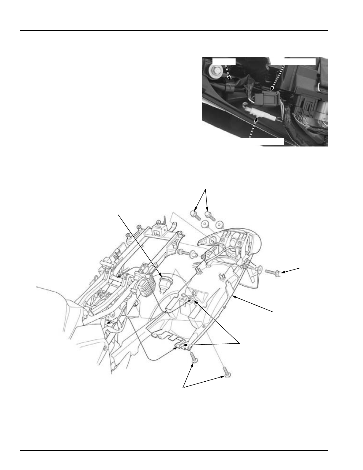
FRAME/BODY PANELS/EXHAUST SYSTEM
LICENSE LIGHT CONNECTOR
9P CONNECTORCLAMP
SIDE
BOLTS
SCREWS
FUSE BOX
HOOKS
UPPER BOLTS
REAR FENDER ASSEMBLY
REAR FENDER
REMOVAL/INSTALLATION
Remove the rear cowl (page 3-8).
Release the wires from the harness clamp.
Disconnect the tail/brake light 9P (Black) and license
light 2P (White) connectors.
Remove the screws, upper bolts and side bolts.
Remove the fuse box from the rear fender.
Release the hooks from the frame, then remove the
rear fender assembly.
3-10
Page 59
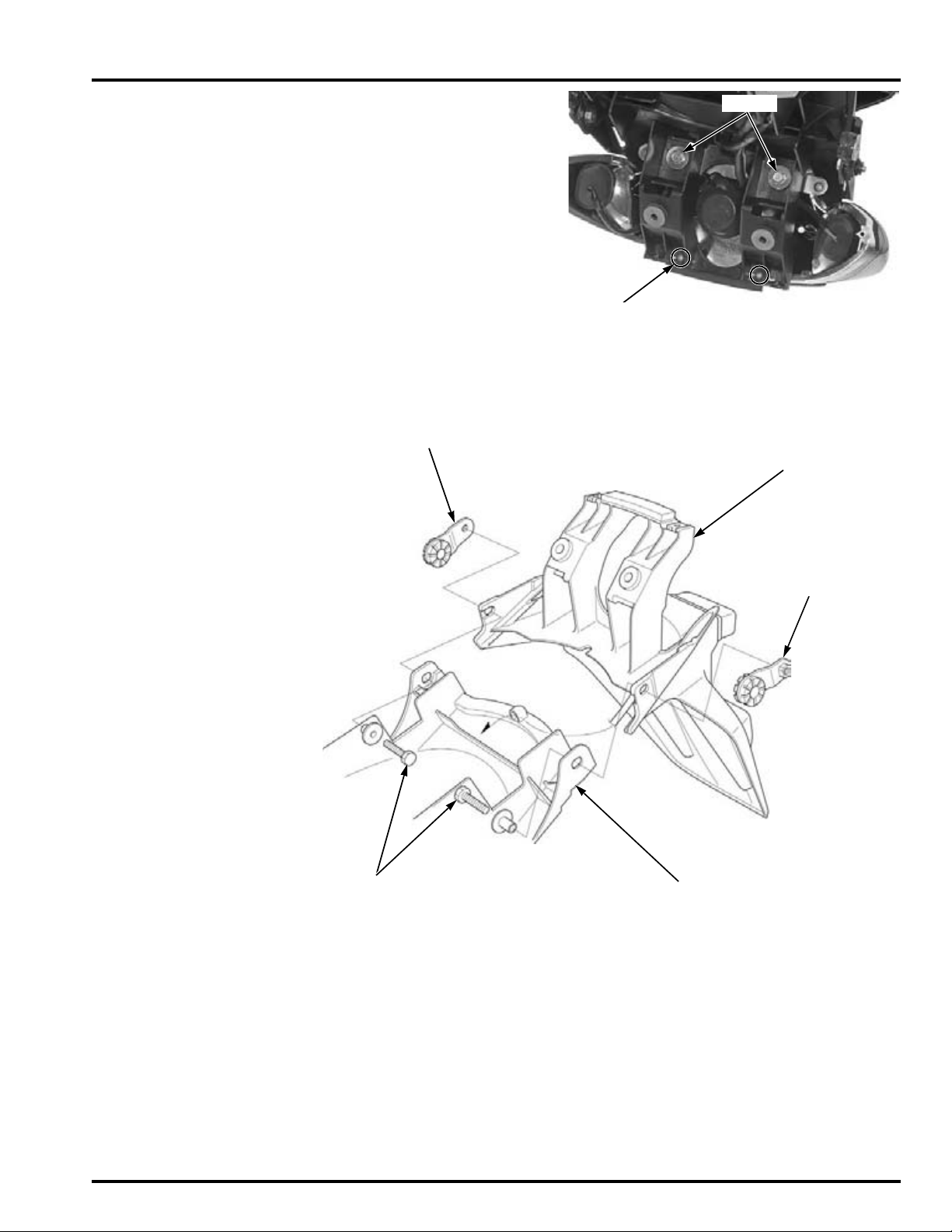
FRAME/BODY PANELS/EXHAUST SYSTEM
BOLTS
SCREWS
BOLTS
REAR FENDER STAY
REAR FENDER
STAY
REAR FENDER
MUDGUARD
Remove the screws and bolts.
Remove the tail/brake light unit from the rear fender
assembly.
Remove the bolts and rear fender stay.
Remove the mudguard from the rear fender.
Assemble the rear fender and install it in the reverse
order.
3-11
Page 60
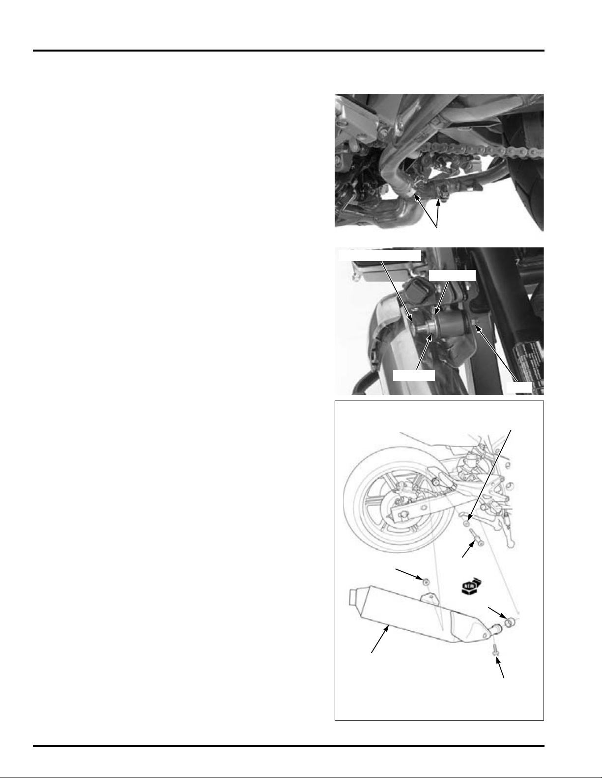
FRAME/BODY PANELS/EXHAUST SYSTEM
MUFFLER BANDS
MOUNTING BOLT
NUT
COLLAR
WASHER
NUT
MUFFLER
GASKET
BAND BOLT
BOLT
COLLAR
MUFFLER
REMOVAL/INSTALLATION
Loosen the muffler band bolt.
Hold the muffler mounting bolt and loosen the nut,
then remove the mounting bolt, collar, washer, nut
and the muffler.
Always replace the
gasket with a new
Remove the muffler gasket and replace it with new
one.
one.
Install the muffler in the reverse order of removal.
Tighten the muffler band bolts securely.
Hold the muffler mounting bolts and tighten the
nuts securely.
3-12
Page 61
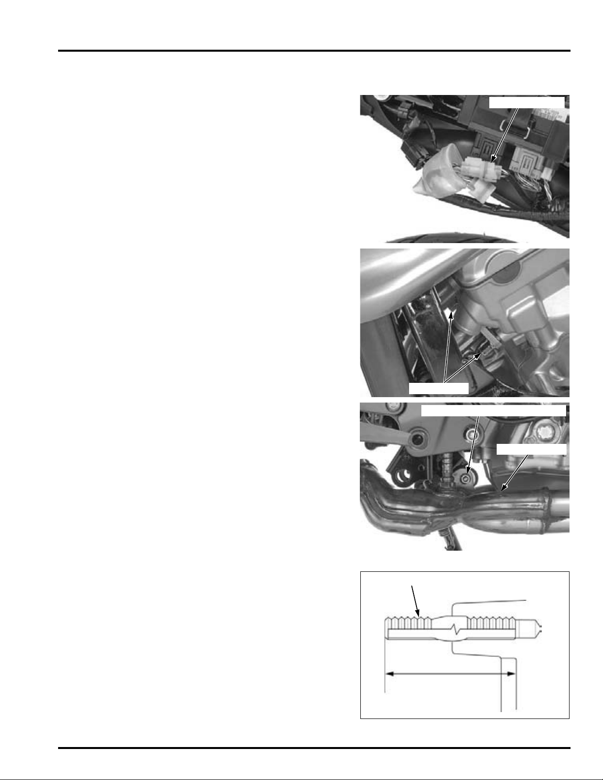
EXHAUST PIPE
4P CONNECTOR
JOINT NUTS
NUT/MOUNTING BOLT/WASHER
EXHAUST PIPE
39 – 40 mm
(1.5 – 1.6 in)
EXHAUST PIPE STUD BOLT
REMOVAL
Remove the following:
– Right rear cowl (page 3-8)
– Mufflers (page 3-12)
Disconnect the O
Remove the exhaust pipe joint nuts.
FRAME/BODY PANELS/EXHAUST SYSTEM
2 sensor 4P (Natural) connector.
Carefully release
2 sensor wire
the O
from the frame.
Remove the nut, mounting bolt and washer.
Remove the exhaust pipe with the O
2 sensor wire.
INSTALLATION
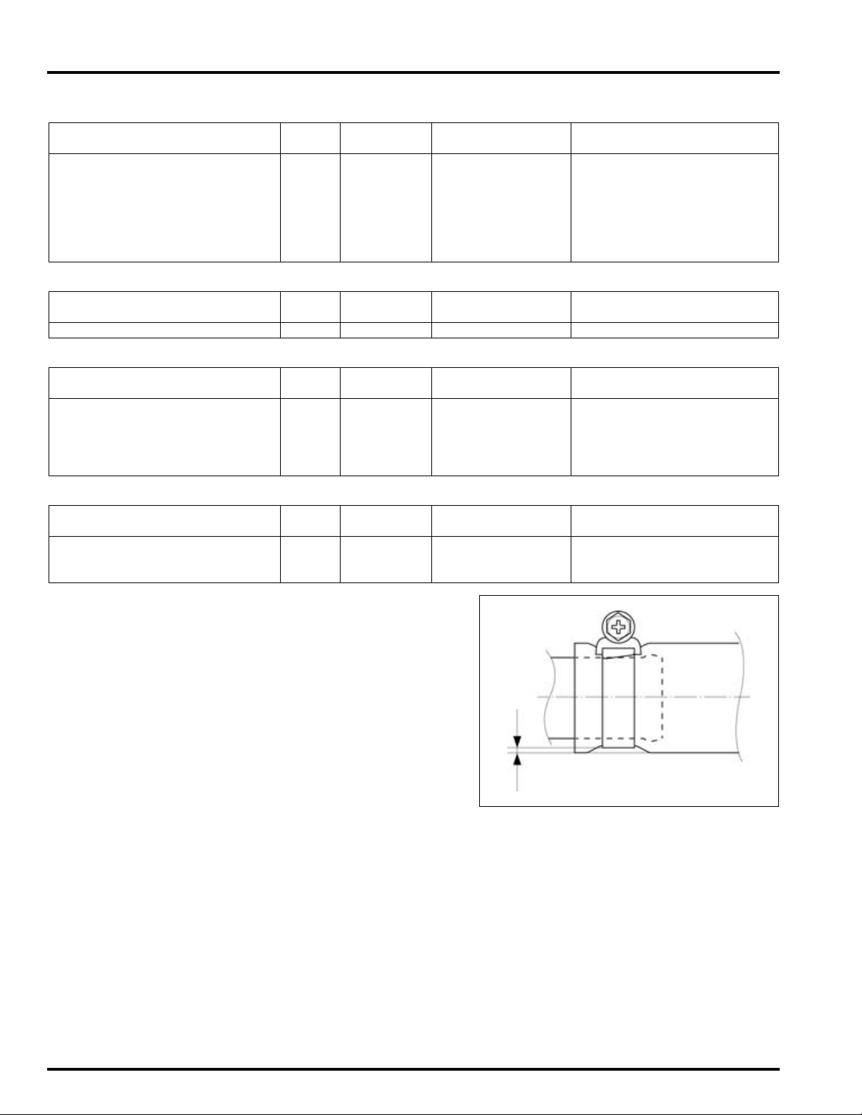
Check that the exhaust pipe stud bolt protrusion
from the exhaust port is specified length as shown.
SPECIFIED LENGTH: 39 – 40 mm (1.5 – 1.6 in)
3-13
Page 62
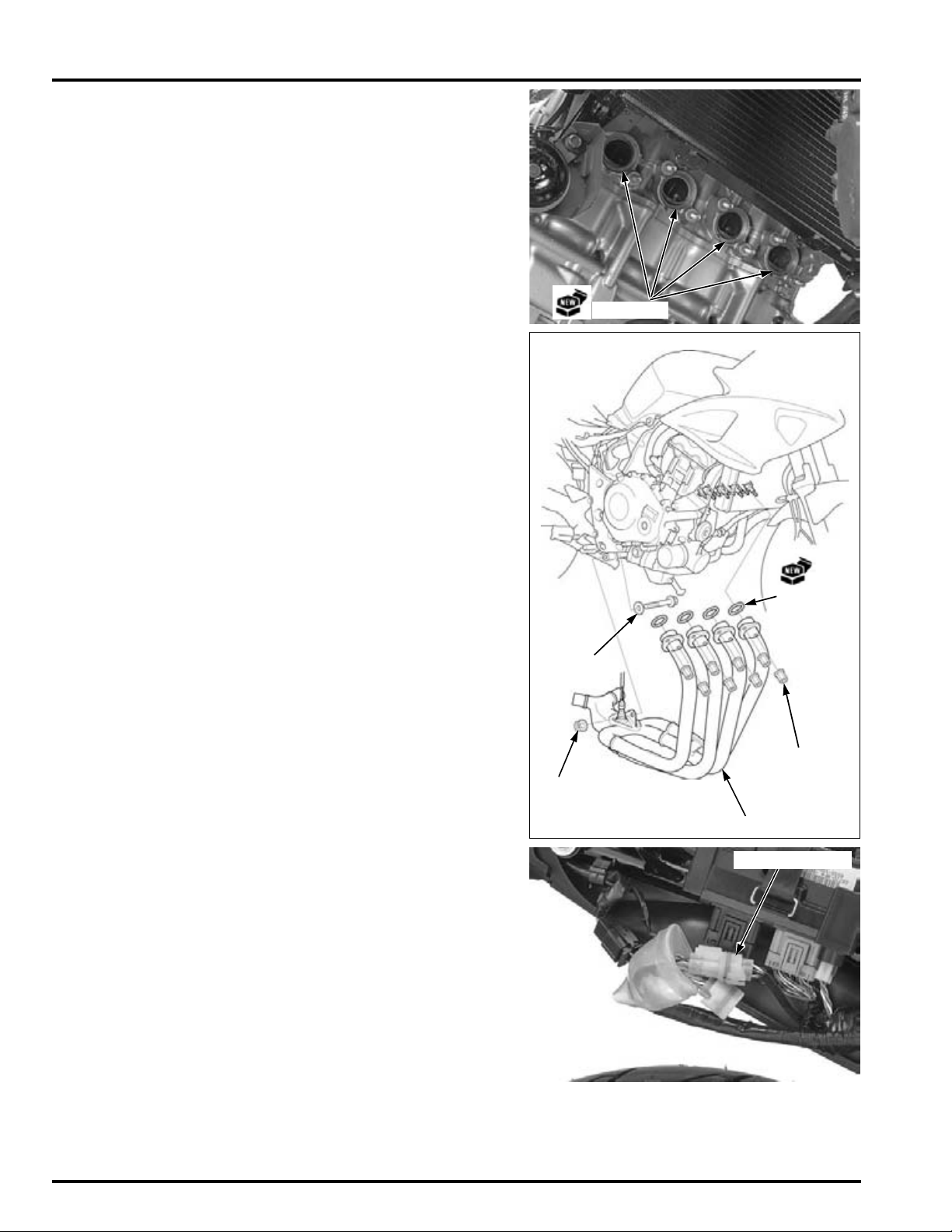
FRAME/BODY PANELS/EXHAUST SYSTEM
GASKETS
GASKETS
EXHAUST PIPE
BOLT/
WASHER
NUT
JOINT NUTS
4P CONNECTOR
Always replace the
gaskets with new
ones.
Refer to "CABLE &
HARNESS
ROUTING" (page 1-
23)
Install the new gaskets to the exhaust ports.
Route the O2 sensor wire properly and install the
exhaust pipe.
Temporarily install the exhaust pipe joint nuts,
exhaust pipe mounting bolt, washer and nut.
First tighten the exhaust pipe joint nuts to the specified torque.
TORQUE: 20 N·m (2.0 kgf·m, 15 lbf·ft)
Hold the exhaust pipe mounting bolt and tighten the
nut securely.
3-14
Connect the O
put the connector boot behind the ECM.
Install the following:
– Right rear cowl (page 3-9)
– Mufflers (page 3-12)
2 sensor 4P (Natural) connector and
Page 63
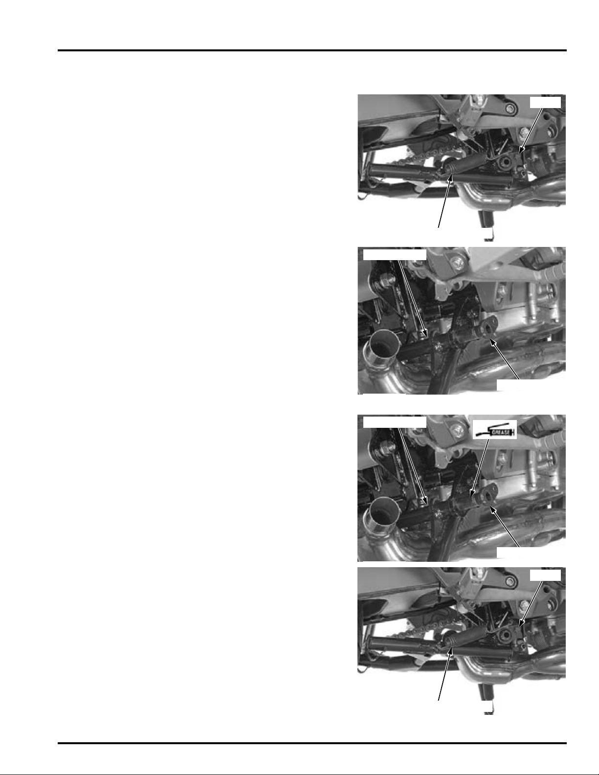
MAIN STAND (CBF1000A)
BOLT
OUTER AND INNER SPRINGS
PIVOT SHAFT
MAIN STAND
PIVOT SHAFT
MAIN STAND
BOLT
OUTER AND INNER SPRINGS
REMOVAL
Support the motorcycle securely using the side
stand.
Remove the right and left mufflers (page 3-12).
Unhook the main stand springs (outer and inner).
Remove the pivot shaft mounting bolt.
Pull the pivot shaft out and remove the main stand.
FRAME/BODY PANELS/EXHAUST SYSTEM
INSTALLATION
Apply multi-purpose grease to the pivot shaft sliding surfaces.
Install the main stand and pivot shaft.
Install and tighten the pivot shaft mounting bolt.
Hook the main stand springs (outer and inner).
Install the right and left mufflers (page 3-12).
After installation, check the main stand operation.
3-15
Page 64
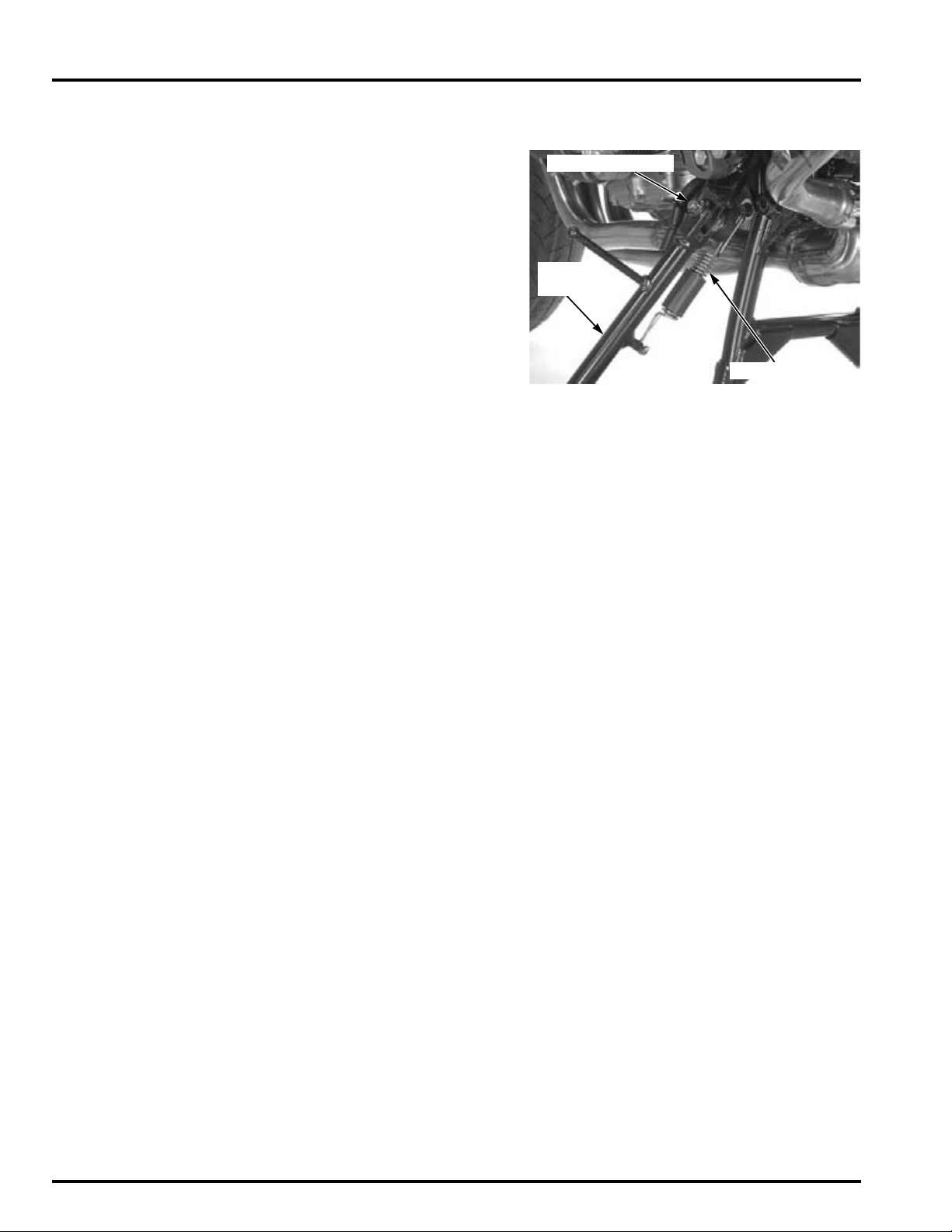
FRAME/BODY PANELS/EXHAUST SYSTEM
RETURN SPRING
PIVOT BOLT/NUT
SIDE
STAND
SIDE STAND
REMOVAL/INSTALLATION
Support the motorcycle using the main stand
(CBF1000A) or other support tool.
Remove the side stand switch (page 21-25).
Retract the side stand.
Unhook the side stand spring.
Hold the pivot bolt and loosen the pivot nut.
Remove the pivot nut, pivot bolt and side stand.
Installation is in the reverse order of removal.
TORQUE:
Side stand pivot bolt:
15 N·m (1.5 kgf·m, 11 lbf·ft)
Side stand pivot nut:
39 N·m (4.0 kgf·m, 29 lbf·ft)
3-16
Page 65
4. MAINTENANCE
4
SERVICE INFORMATION ··························· 4-2
MAINTENANCE SCHEDULE ······················ 4-4
FUEL LINE ··················································· 4-5
THROTTLE OPERATION····························· 4-6
AIR CLEANER·············································· 4-7
CRANKCASE BREATHER ··························· 4-7
SPARK PLUG ·············································· 4-8
VALVE CLEARANCE································· 4-11
ENGINE OIL/OIL FILTER ·························· 4-16
RADIATOR COOLANT ······························ 4-19
COOLING SYSTEM··································· 4-19
DRIVE CHAIN SLIDER ······························ 4-25
BRAKE FLUID ··········································· 4-25
BRAKE PAD WEAR··································· 4-26
BRAKE SYSTEM······································· 4-27
BRAKE LIGHT SWITCH ···························· 4-28
HEADLIGHT AIM ······································ 4-28
CLUTCH SYSTEM ···································· 4-28
CLUTCH FLUID ········································· 4-29
SIDE STAND ············································· 4-30
SUSPENSION ··········································· 4-30
NUTS, BOLTS, FASTENERS···················· 4-31
SECONDARY AIR SUPPLY SYSTEM······· 4-20
DRIVE CHAIN ············································ 4-21
WHEELS/TIRES ········································ 4-32
STEERING HEAD BEARINGS ·················· 4-32
4-1
Page 66
MAINTENANCE
MAINTENANCE
SERVICE INFORMATION
GENERAL
• Place the motorcycle on a level ground before starting any work.
• The exhaust contains poisonous carbon monoxide gas that may cause loss of consciousness and may lead to death.
Run the engine in an open area or with an exhaust evacuation system in and enclosed area.
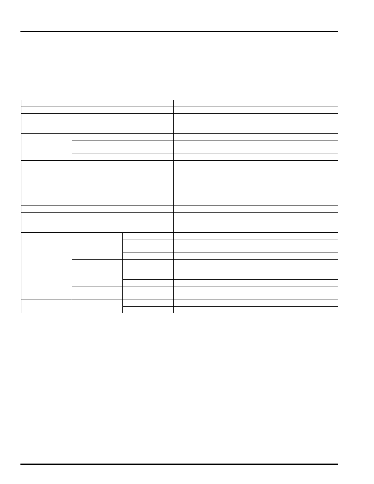
SPECIFICATIONS
ITEM SPECIFICATIONS
Throttle grip free play 2 – 6 mm (1/12 – 1/4 in)
Spark plug NGK CR8EH-9
DENSO U24FER9
Spark plug gap 0.80 – 0.90 mm (0.031 – 0.035 in)
Valve
clearance
Engine oil
capacity
Engine oil Suggested oil:
Engine idle speed 1,200 ± 100 mi n
Drive chain slack 20 – 30 mm (4/5 – 1-1/5 in)
Recommended brake fluid DOT 4
Recommended clutch fluid DOT 4
Tire size Front 120/70ZR17M/C (58W)
Tire brand Bridgestone Front BT57F RADIAL U
Tire air
pressure
Minimum tire tread depth Front 1.5 mm (0.06 in)
IN 0.16 ± 0.03 mm (0.006 ± 0.001 in)
EX 0.32 ± 0.03 mm (0.013 ± 0.001 in)
After draining 2.7 liter (2.9 US qt, 2.4 Imp qt)
After oil filter change 3.5 liter (3.7 US qt, 3.1 lmp qt)
Honda "4-stroke motorcycle oil" or an equivalent
Oil recommendation:
API classification: SG or higher (except oils labeled as
energy conserving on the circular API service label)
Viscosity: SAE 10W-30
JASO T 903 standard: MA
Rear 160/60ZR17 M/C (69W)
Rear BT57R RADIAL E
Michelin Front Pilot ROAD B
Rear Pilot ROAD A
Driver only Front 250 kPa (2.50 kgf/cm
Rear 290 kPa (2.90 kgf/cm
Driver and
passenger
Front 250 kPa (2.50 kgf/cm
Rear 290 kPa (2.90 kgf/cm
Rear 2.0 mm (0.08 in)
-1
(rpm)
2
, 36 psi)
2
, 42 psi)
2
, 36 psi)
2
, 42 psi)
TORQUE VALUES
Spark plug 16 N·m (1.6 kgf·m, 12 lbf·ft)
Timing hole cap 18 N·m (1.8 kgf·m, 13 lbf·ft) Apply grease to the threads.
Engine oil filter cartridge 26 N·m (2.7 kgf·m, 19 lbf·ft) Apply engine oil to the threads and O-
Engine oil drain bolt 30 N·m (3.1 kgf·m, 22 lbf·ft)
Drive chain adjuster lock nut 21 N·m (2.1 kgf·m, 15 lbf·ft)
Rear axle nut 108 N·m (11.0 kgf·m, 80 lbf·ft) U-nut
Air cleaner duct mounting screw 1.1 N·m (0.1 kgf·m, 0.8 lbf·ft)
Rear master cylinder push rod lock nut 17 N·m (1.7 kgf·m, 13 lbf·ft)
Oil filter boss See page 4-18 Apply a locking agent to the threads.
ring.
4-2
Page 67
TOOLS
MAINTENANCE
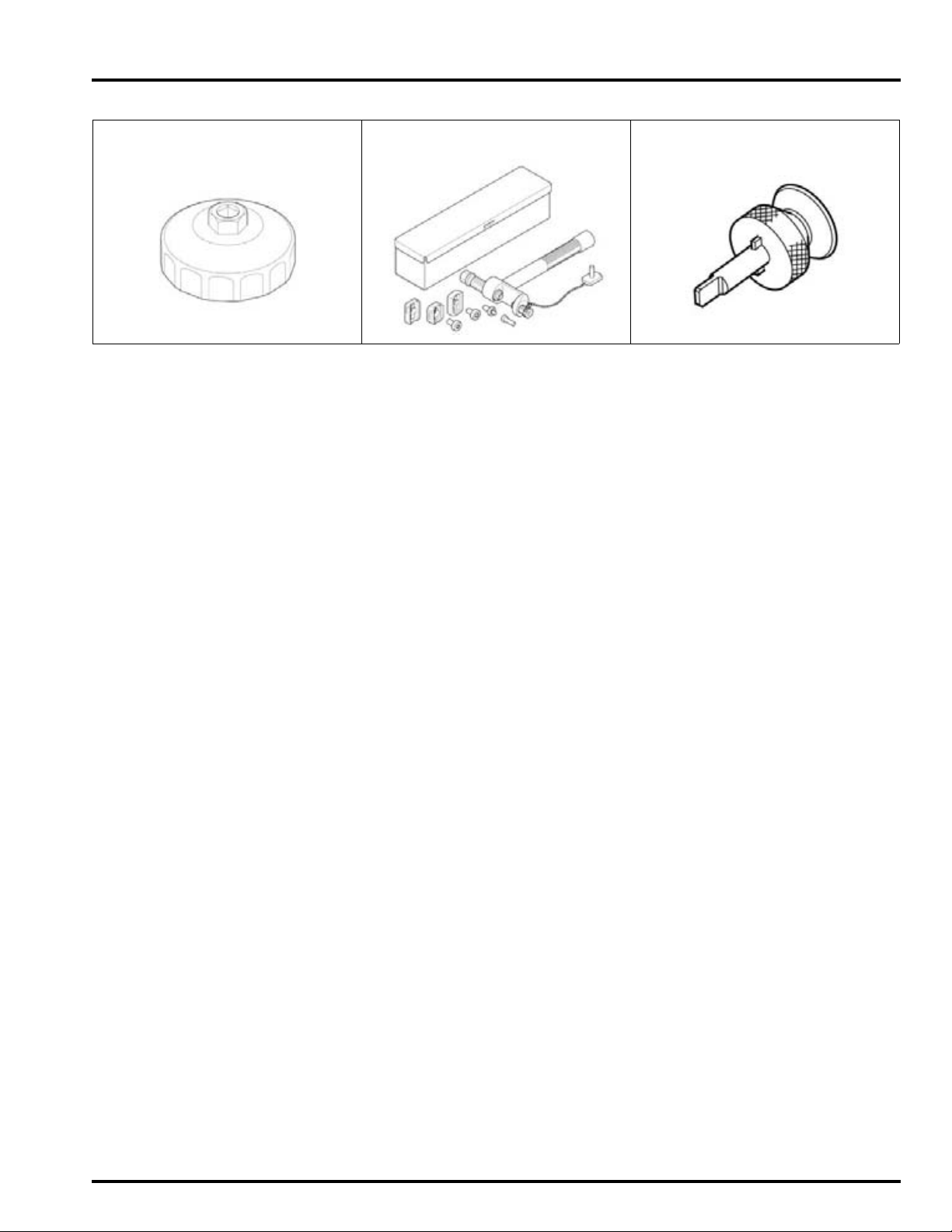
Oil filter wrench
07HAA-PJ70101
Drive chain tool set
07HMH-MR10103
Cam chain tensioner holder
07ZMG-MCAA400
4-3
Page 68
MAINTENANCE
MAINTENANCE SCHEDULE
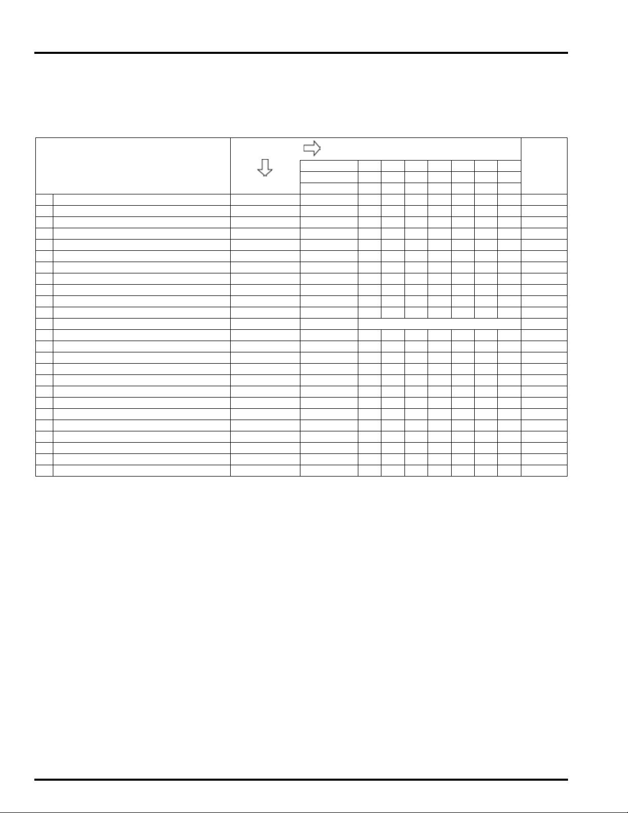
Perform the Pre-ride inspection in the Owner's Manual at each scheduled maintenance period.
I: Inspect and Clean, Adjust, Lubricate or Replace if necessary. C: Clean. R: Replace. A: Adjust. L: Lubricate.
The following items require some mechanical knowledge. Certain items (particularly those marked * and **) may require
more technical information and tools. Consult an authorized Honda dealer.
FREQUENCY WHICHEVER
ITEMS Months 6 12 18 24 30 36
* FUEL LINE III4-5
* THROTTLE OPERATION I I I 4-6
AIR CLEANER NOTE 2 I I 4-7
CRANKCASE BREATHER NOTE 3 CCCCCC 4-7
* SPARK PLUG IRI4-8
* VALVE CLEARANCE I4-11
ENGINE OIL R R R R 4-16
ENGINE OIL FILTER R R R R 4-16
RADIATOR COOLANT NOTE 4 I I R 4-19
* COOLING SYSTEM I I I 4-19
* SECONDARY AIR SUPPLY SYSTEM I I I 4-20
DRIVE CHAIN EVERY 1,000 km (600 mi) I, L 4-21
DRIVE CHAIN SLIDER I I I 4-25
BRAKE FLUID NOTE 4 I I R I I R 4-25
BRAKE PAD WEAR IIIIII 4-26
BRAKE SYSTEM IIII4-27
* BRAKE LIGHT SWITCH I I I 4-28
* HEADLIGHT AIM I I I 4-28
CLUTCH SYSTEM IIIIIII 4-28
CLUTCH FLUID NOTE 4 I I R I I R 4-29
SIDE STAND I I I 4-30
*SUSPENSION I I I 4-30
*NUTS, BOLTS, FASTENERS IIII4-31
** WHEELS/TIRES I I I 4-32
**STEERING HEAD BEARINGS IIII4-32
COMES FIRST
ODOMETER READING (NOTE 1)
x 1,000 km 1 6 12 18 24 30 36
x 1,000 mi 0.6 4 8 12 16 20 24
REFER
TO PAGE
* Should be serviced by an authorized Honda dealer, unless the owner has proper tools and service data and is
mechanically qualified
** In the interest of safety, we recommended these items be serviced only by an authorized Honda dealer
Honda recommends that an authorized Honda dealer should road test your motorcycle after each periodic maintenance is
carried out.
NOTES:
1. At higher odometer reading, repeat at the frequency interval established here.
2. Service more frequently when riding in unusually wet or dusty areas.
3. Service more frequently when riding in rain or at full throttle.
4. Replace every 2 years, or at indicated odometer interval, whichever comes first. Replacement requires mechanical skill.
4-4
Page 69
FUEL LINE
BOLTS/COLLARS
NUT/PIVOT BOLT
HANDLE
PIN SPANNER
FUEL FEED HOSE
MAINTENANCE
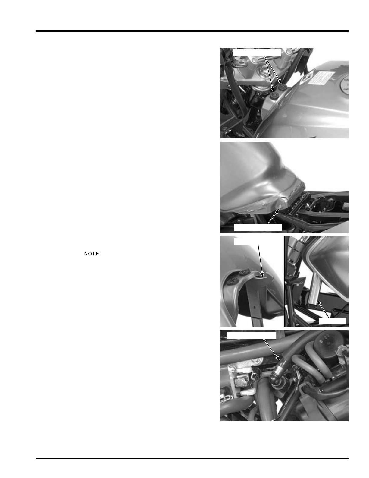
Remove the following:
– Seat (page 3-3)
– Side covers (page 3-4)
– Right and left front cowl (page 3-6)
– Inner panel (page 3-5)
Remove the fuel tank front mounting bolts and collars.
Hold the fuel tank rear pivot bolt and loosen the nut.
Lift the fuel tank and support it using the equipped
tools (pin spanner and handle) as shown.
• Support the fuel tank mounting bolt hole with
the pin spanner and hook the handle on the stay
of the frame.
Check the fuel lines for deterioration, damage or
leakage. Replace the fuel line if necessary (page 6-
51).
Check the fuel rails and injectors for damage or
leakage. Replace them if necessary (page 6-73).
Check the fuel pump mounting area for leakage.
Replace the fuel pump packing if necessary (page 6-
55).
4-5
Page 70
MAINTENANCE
HOSE JOINTS
BOLTS/COLLARS
NUT/PIVOT BOLT
2 – 6 mm
(1/12 – 1/4 in)
ADJUSTER
LOCK NUT
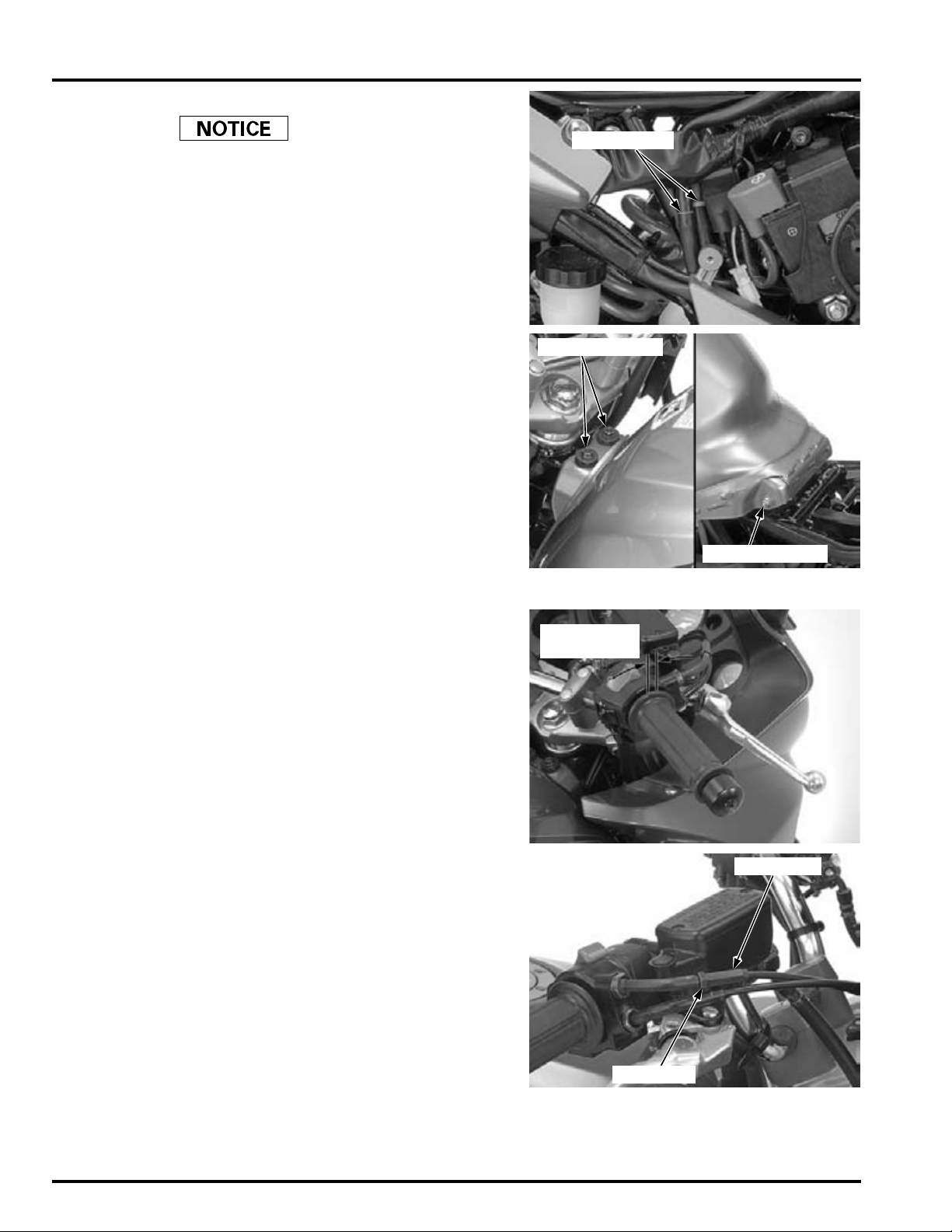
Remove a support tools, then lower the fuel tank.
• Route the hoses, wires and harness properly
• Be careful not to damage the harness and hoses.
• After installing the fuel tank, make sure the drain,
• Check the hose joints for loose or disconnection.
Install the fuel tank front mounting bolts and collars.
Tighten the fuel tank mounting bolts and rear pivot
nut securely.
Install the removed parts in the reverse order of
removal.
(page 1-23).
breather and fuel hoses are not kinked or bound.
THROTTLE OPERATION
Check for smooth throttle grip full opening and
automatic full closing in all steering positions.
Check the throttle cables and replace them if they
are deteriorated, kinked or damaged (page 6-69).
Lubricate the throttle cables, if throttle operation is
not smooth.
Measure the free play at the throttle grip flange.
FREE PLAY: 2 – 6 mm (1/12 – 1/4 in)
Throttle grip free play can be adjusted at either end
of the throttle cable.
Minor adjustment is made with the throttle grip side
adjuster.
Adjust the free play by loosening the lock nut and
turning the adjuster.
4-6
Page 71
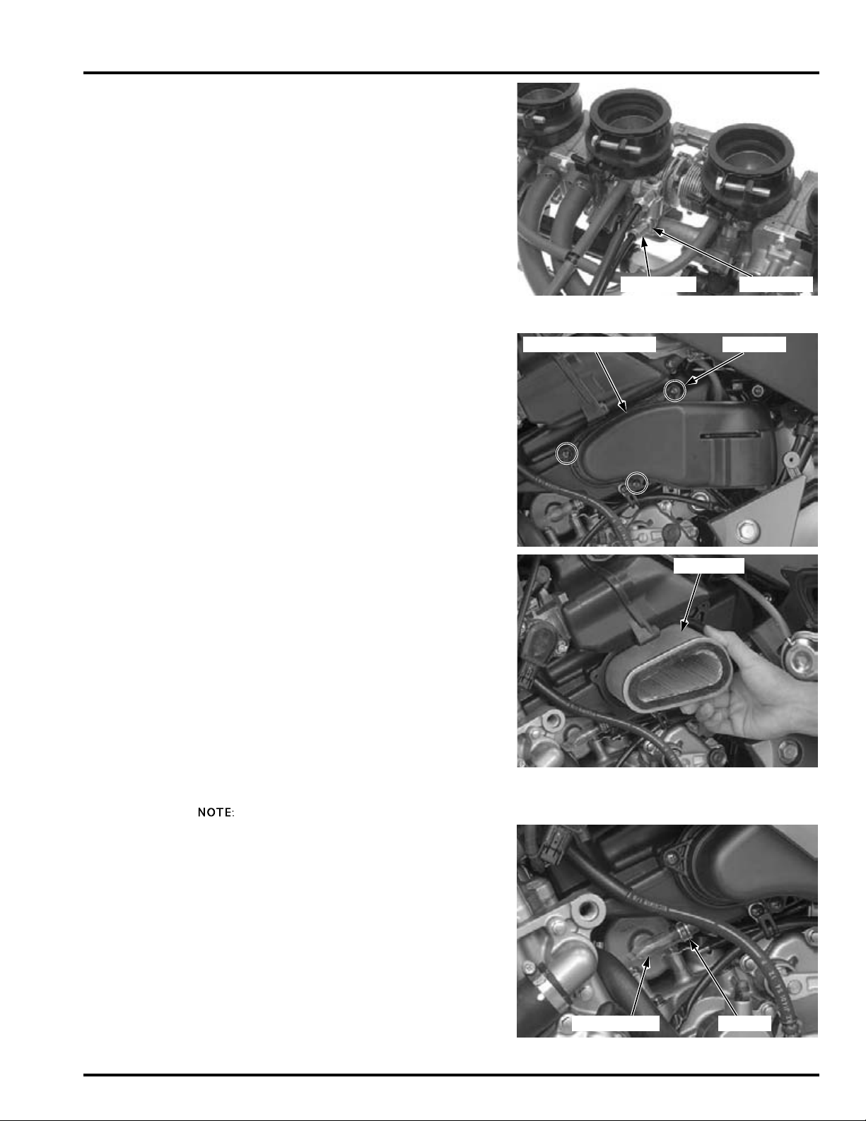
Major adjustment is made with the throttle body
ADJUSTER LOCK NUT
AIR CLEANER DUCT SCREWS
ELEMENT
DRAIN TUBE CLAMP
side adjuster.
Remove the air cleaner housing (page 6-60).
Adjust the free play by loosening the lock nut and
turning the adjuster.
After adjustment, tighten the lock nut securely.
Install the air cleaner housing and recheck the throttle operation (page 6-67).
Replace any damaged parts, if necessary.
AIR CLEANER
Remove the left side cover (page 3-4).
Remove the screws and air cleaner duct.
MAINTENANCE
Remove and inspect the air cleaner elements in
accordance with the maintenance schedule (page 4-
4).
Clean the air cleaner element with the compressed
air from outside of the element.
Install the air
cleaner element
with its opening
facing out.
Install the removed parts in the reverse order of
removal.
TORQUE:
Air cleaner duct mounting screw:
CRANKCASE BREATHER
• Service more frequently when ridden in rain, at
full throttle, or after the motorcycle is washed or
overturned. Service if the deposit level can be
seen in the drain tube.
Remove the left side cover (page 3-4).
Remove the crankcase breather drain tube and
drain the deposits into a suitable container, then
reinstall the drain tube with the tube clamp.
1.1 N·m (0.1 kgf·m, 0.8 lbf·ft)
4-7
Page 72

MAINTENANCE
BOLTS/NUTS
IGNITION COIL
CONNECTORS
BOLTS
IGNITION COIL
SPARK PLUG CAPS
BOLT
BREATHER HOSE
SPARK PLUG
REMOVAL
Lift and support the fuel tank (page 4-5).
Remove the ignition coil mounting bolts and nuts to
disconnect the #2 and #3 spark plug caps.
Disconnect the #1/#4 ignition coil connectors.
Remove the mounting bolts to disconnect the #1
and #4 spark plug caps.
Disconnect the #1 and #2 spark plug caps.
If the #3 spark plug cap is hard to be disconnected,
disconnect the crankcase breather hose and remove
the thermostat case mounting bolt.
4-8
Page 73
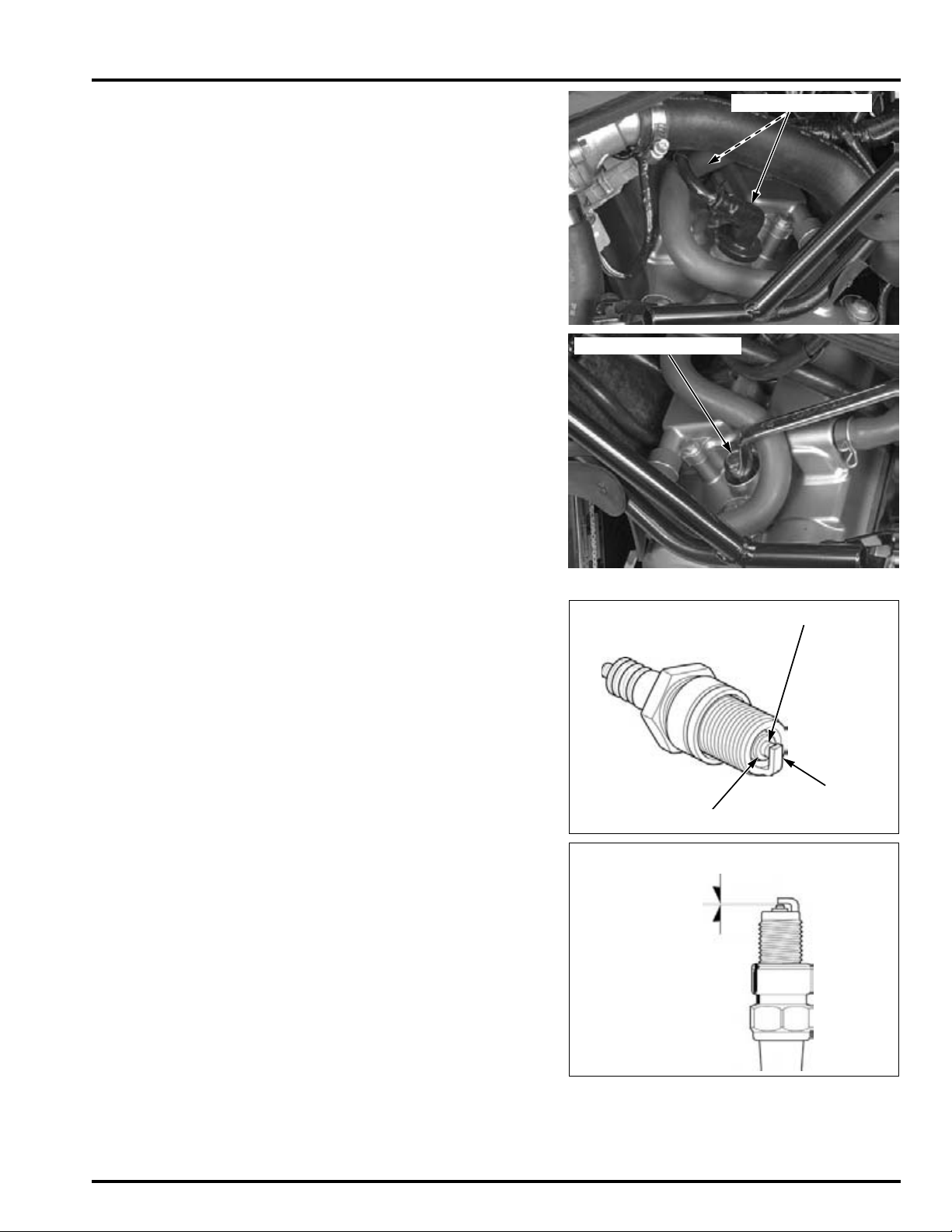
Disconnect the #3 and #4 spark plug caps.
SPARK PLUG CAPS
SPARK PLUG WRENCH
CENTER ELECTRODE
INSULATOR
SIDE
ELECTRODE
0.8 – 0.9 mm
(0.031 – 0.035 in)
Remove the spark plugs using a equipped spark
plug wrench or an equivalent tool.
MAINTENANCE
INSPECTION
Check the insulator for cracks or damage, and the
electrodes for wear, fouling or discoloration.
Replace the spark plugs if necessary.
SPECIFIED SPARK PLUG:
NGK: CR8EH-9
DENSO: U24FER9
Clean the spark plug electrodes with a wire brush or
special plug cleaner.
Check the gap between the center and side electrodes with a wire type feeler gauge.
SPARK PLUG GAP:
0.80 – 0.90 mm (0.031 – 0.035 in)
If necessary, adjust the gap by bending the side
electrode carefully.
4-9
Page 74
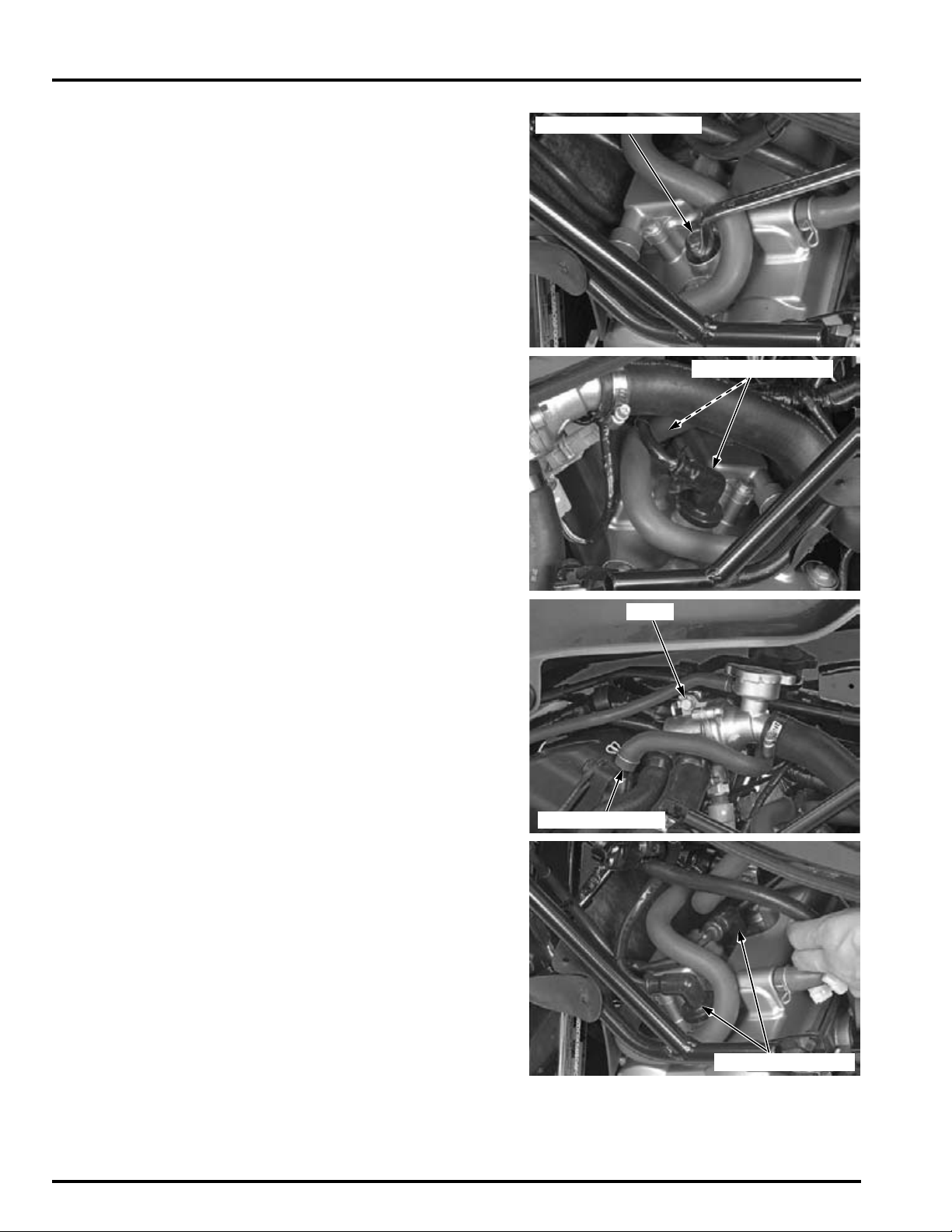
MAINTENANCE
SPARK PLUG WRENCH
SPARK PLUG CAPS
BOLT
BREATHER HOSE
SPARK PLUG CAPS
INSTALLATION
For new spark plug;
install and hand-
tighten the spark
plug, then tighten it
about 1/2 turns
after the sealing
washer contacts
the seat of the plug
Thread each spark plug in by hand to prevent crossthreading, and tighten them using a spark plug
wrench.
TORQUE: 16 N·m (1.6 kgf·m, 12 lbf·ft)
hole.
Refer to "Cable &
Harness Routing"
(page 1-23).
Route the spark plug wires properly and connect the
#3 and #4 spark plug caps.
If the thermostat case is removed, install it onto the
frame and tighten the mounting bolt.
Connect the crankcase breather hose.
Refer to "Cable &
Harness Routing"
(page 1-23).
4-10
Route the spark plug wires properly and connect the
#1 and #2 spark plug caps.
Page 75
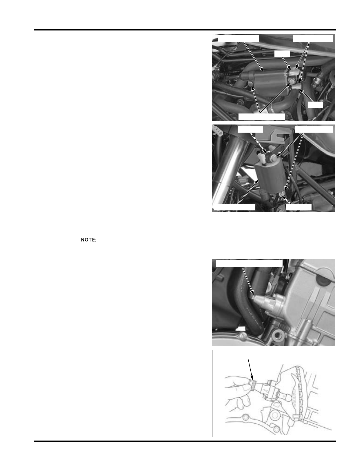
Install the #1/#4 ignition coil with the spacers, and
CONNECTORS
BOLTS/SPACERS
IGNITION COIL
Y/Bu
Bl/W
BOLTS/NUTS
IGNITION COIL
SPACER
SPACER
BOLT/SEALING WASHER
CAM CHAIN TENSIONER HOLDER
tighten the mounting bolts.
Connect the ignition coil connectors.
Install the #2/#3 ignition coil with the spacers.
Install the mounting bolts, spacers and nuts, then
tighten the nuts securely.
Install the removed parts in the reverse order.
MAINTENANCE
VALVE CLEARANCE
INSPECTION
• Check the engine idle speed (page 6-76) after the
Inspect and adjust
the valve clearance
while the engine is
cold (below 35
Remove the cylinder head cover (page 9-6).
Remove the cam chain tensioner lifter sealing bolt
and sealing washer.
°
C/
°
F).
95
Turn the tensioner lifter shaft fully in (clockwise)
and secure it using the special tool to prevent damaging the cam chain.
TOOL:
Cam chain tensioner holder 07ZMG-MCAA400
valve clearance inspection.
4-11
Page 76
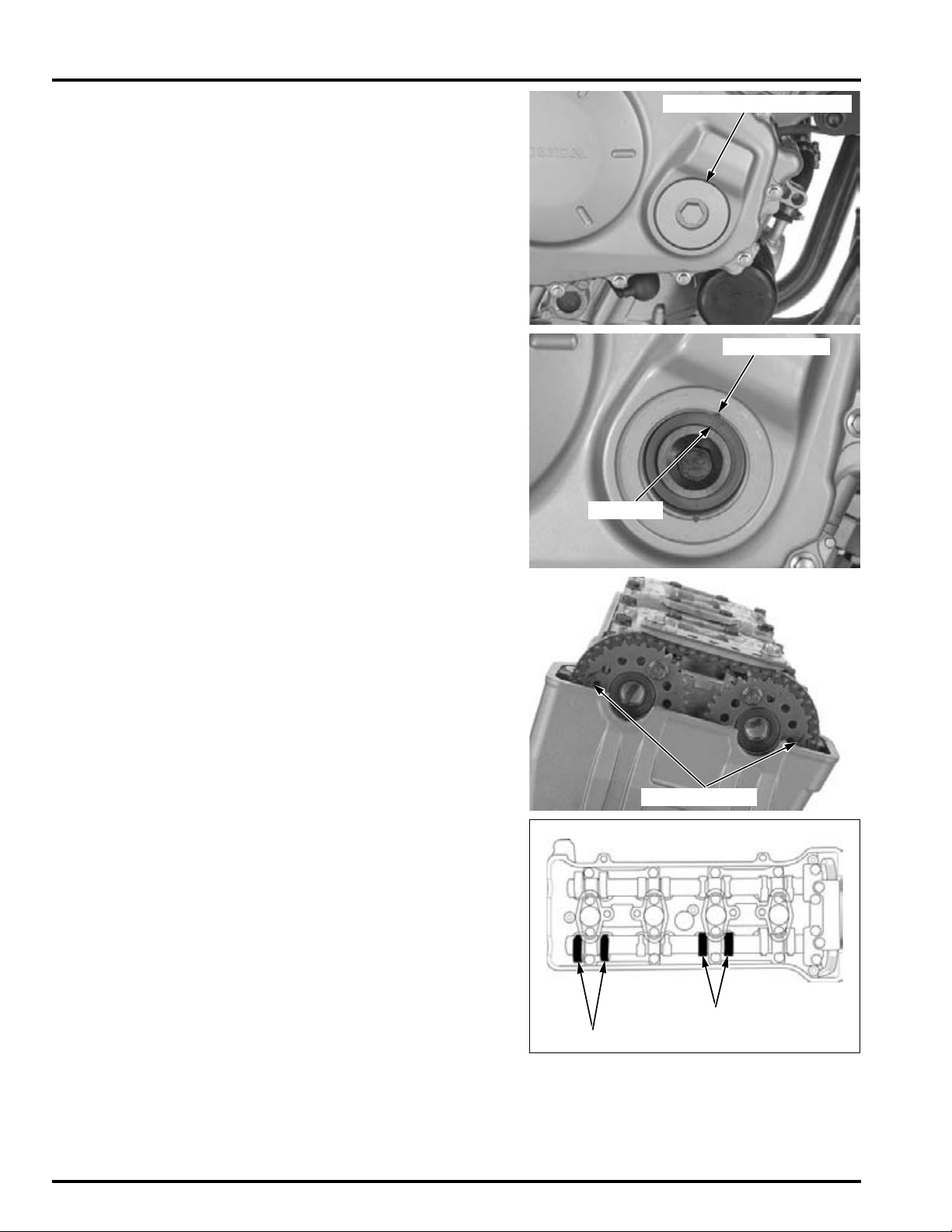
MAINTENANCE
TIMING HOLE CAP/O-RING
INDEX NOTCH
"T" MARK
TIMING MARKS
No.3 CAM LOBES (IN)
No.1 CAM LOBES (IN)
Remove the timing hole cap and O-ring.
Turn the crankshaft clockwise, align the "T" mark on
the starter clutch outer with the index notch on the
right crankcase cover.
Record the
clearance for each
valve for reference
in shim selection if
adjustment is
required.
The timing marks ("IN" and "EX") on the cam
sprockets must be flush with the cylinder head surface and facing outward as shown.
If the timing marks on the cam sprockets are facing
inward, turn the crankshaft clockwise one full turn
(360°) and realign the timing marks with the cylinder head surface so they are facing outward.
Insert the feeler gauge between the valve lifter and
cam lobe.
Check the valve clearance for the No.1 and No.3 cylinder intake valves using a feeler gauge.
VALVE CLEARANCE:
IN: 0.16 ± 0.03 mm (0.006 ± 0.001 in)
4-12
Page 77
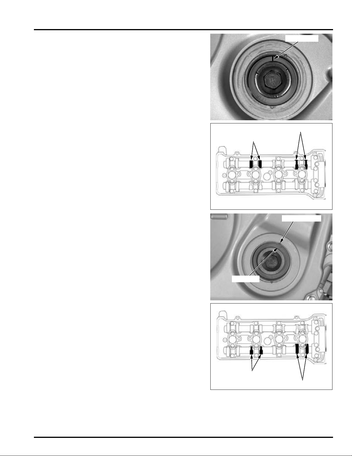
Turn the crankshaft clockwise 1/2 turn (180°), align
INDEX LINE
No.4 CAM LOBES (EX)
No.2 CAM LOBES (EX)
INDEX NOTCH
"T" MARK
No.2 CAM LOBES (IN)
No.4 CAM LOBES (IN)
the index line on the starter clutch outer so that it is
facing up as shown.
MAINTENANCE
Record the
clearance for each
valve for reference
in shim selection if
adjustment is
required.
Check the valve clearance for the No.2 and No.4 cylinder exhaust valves using a feeler gauge.
VALVE CLEARANCE:
EX: 0.32 ± 0.03 mm (0.013 ± 0.001 in)
Turn the crankshaft clockwise 1/2 turn (180°), align
the "T" mark on the starter clutch outer with the
index notch on the right crankcase cover.
Record the
clearance for each
valve for reference
in shim selection if
adjustment is
Check the valve clearance for the No.2 and No.4 cylinder intake valves using feeler gauge.
VALVE CLEARANCE:
IN: 0.16 ± 0.03 mm (0.006 ± 0.001 in)
required.
4-13
Page 78
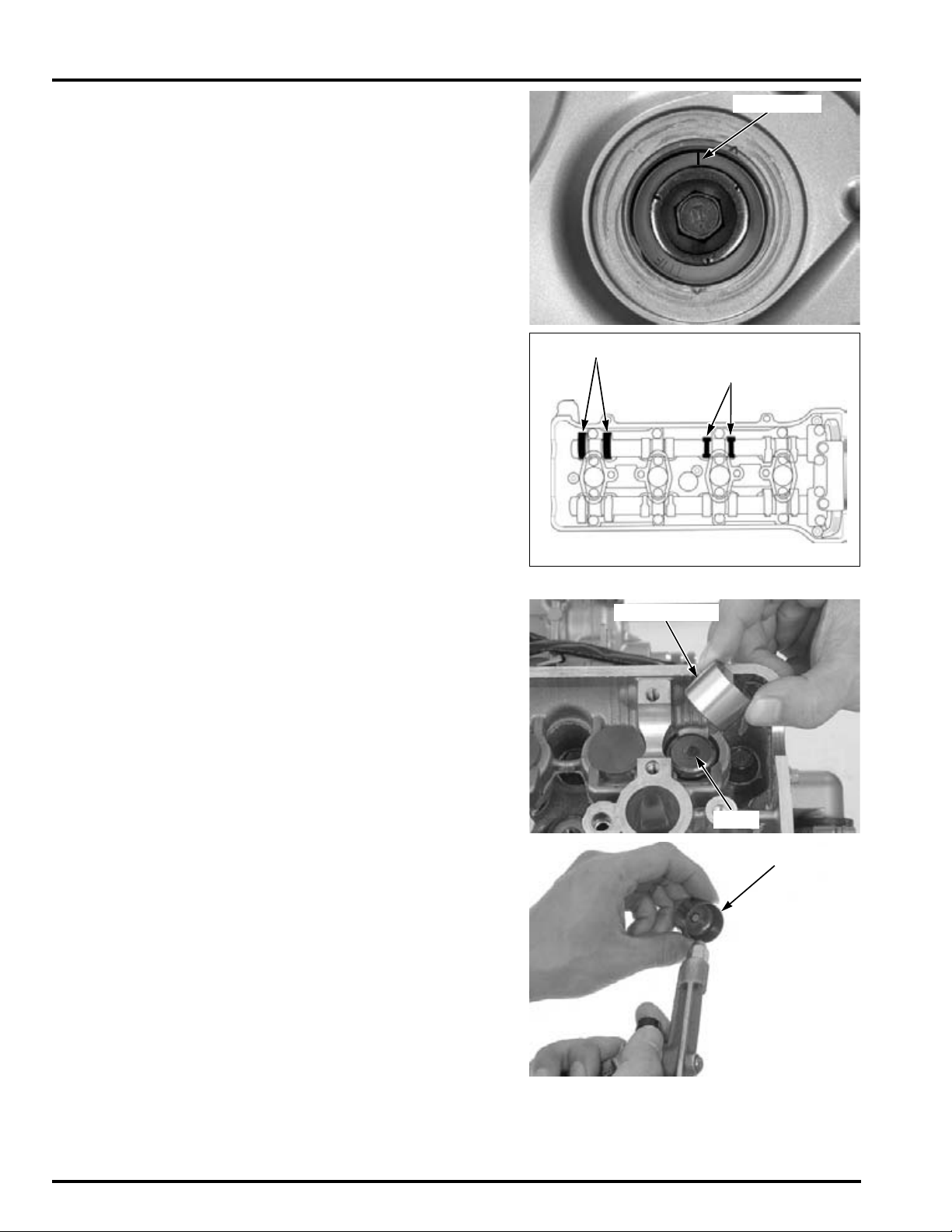
MAINTENANCE
INDEX LINE
No.1 CAM LOBES (EX)
No.3 CAM LOBES (EX)
SHIM
VALVE LIFTER
VALVE LIFTER
Turn the crankshaft clockwise 1/2 turn (180°), align
the index line on the starter clutch outer so that it is
facing up as shown.
Record the
clearance for each
valve for reference
in shim selection if
adjustment is
required.
It is not necessary
to remove the cam
sprocket from the
camshaft except
when replacing the
camshaft and/or
cam sprocket.
Check the valve clearance for the No.1 and No.3 cylinder exhaust valves using a feeler gauge.
VALVE CLEARANCE:
EX: 0.32 ± 0.03 mm (0.013 ± 0.001 in)
ADJUSTMENT
Remove the camshafts (page 9-8).
Remove the valve lifters and shims.
• Shim may stick to the inside of the valve lifter.
Do not allow the shims to fall into the crankcase.
• Mark all valve lifters and shims to ensure correct
reassembly in their original locations.
• The valve lifter can be easily removed with a
valve lapping tool or magnet.
• The shims can be easily removed with a tweezers or magnet.
4-14
Clean the valve shim contact area in the valve lifter
with compressed air.
Page 79
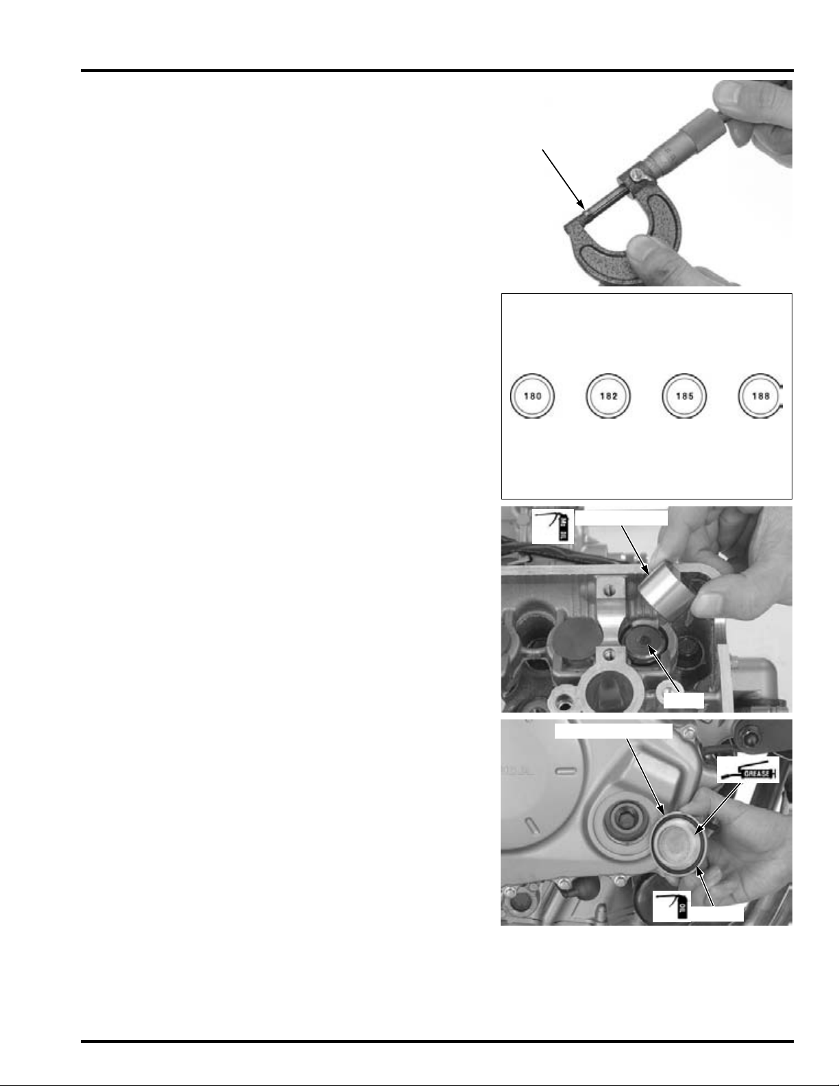
Measure the shim thickness and record it.
SHIM
1.875 mm
1.85 mm
1.8 0 m m
1.825 mm
SHIM
VALVE LIFTER
O-RING
TIMING HOLE CAP
MAINTENANCE
Sixty-nine different
thickness shims are
available from the
thinnest 1.200 mm
thickness shim to
the thickest 2.900
mm thickness shim
in intervals of 0.025
mm.
Install the shims
and valve lifters in
their original
locations
Calculate the new shim thickness using the equation below.
A = (B – C) + D
A: New shim thickness
B: Recorded valve clearance
C: Specified valve clearance
D: Old shim thickness
• Make sure of the correct shim thickness by measuring the shim by micrometer.
• Reface the valve seat if carbon deposit result in a
calculated dimension of over 2.900 mm.
Install the newly selected shim on the valve spring
retainer.
Apply molybdenum disulfide oil to the valve lifters.
Install the valve lifters into the valve lifter holes.
Install the camshafts (page 9-25).
Rotate the camshafts by rotating the crankshaft
clockwise several times.
Recheck the valve clearance.
Check that the O-
ring is in good
condition, replace if
necessary.
Apply oil to the timing hole cap O-ring.
Apply grease the timing hole cap threads.
Tighten the timing hole cap to the specified torque.
TORQUE: 18 N·m (1.8 kgf·m, 13 lbf·ft)
Install the removed parts in the reverse order of
removal.
4-15
Page 80
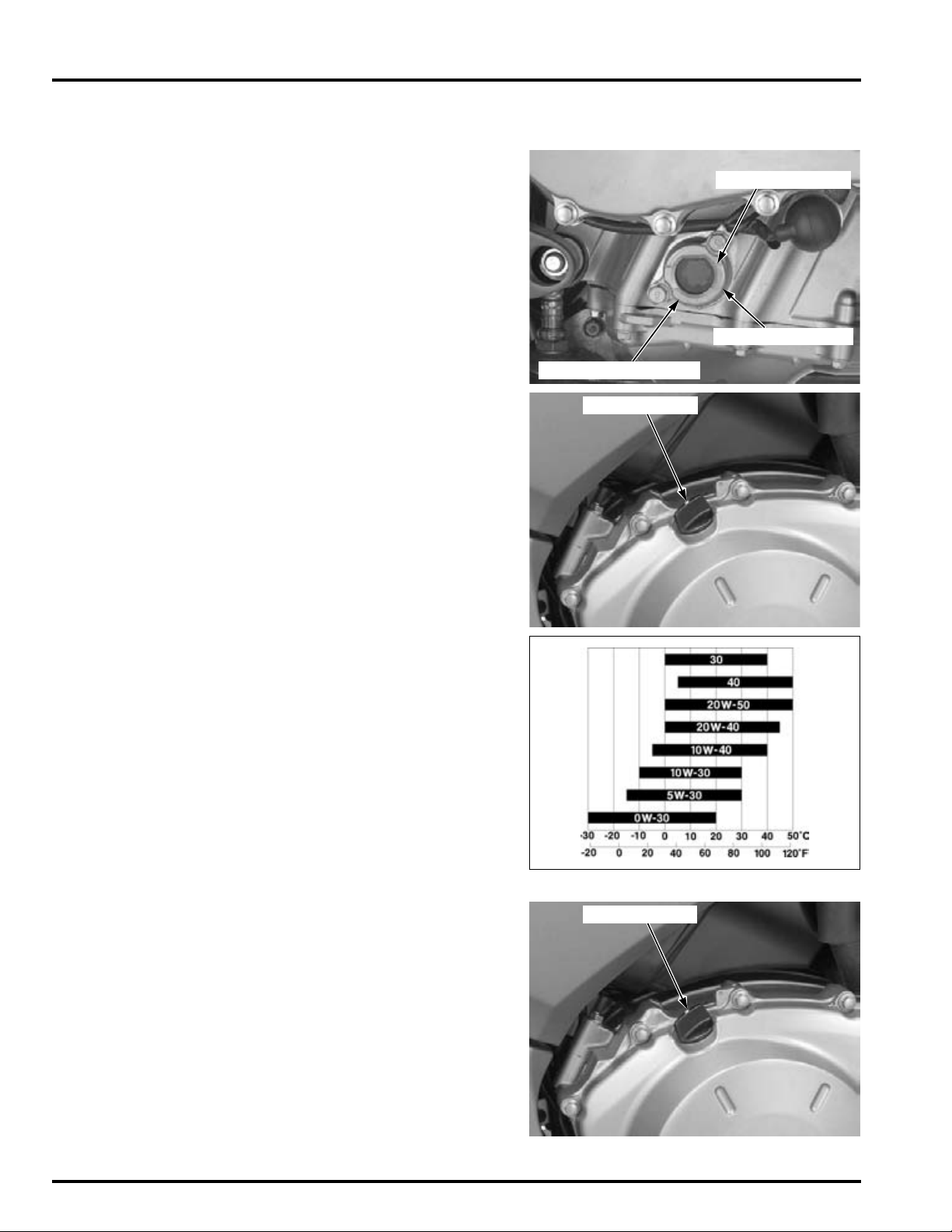
MAINTENANCE
INSPECTION WINDOW
UPPER LEVEL LINE
LOWER LEVEL LINE
OIL FILLER CAP
OIL FILLER CAP
ENGINE OIL/OIL FILTER
OIL LEVEL INSPECTION
Start the engine and let it idle for 3 – 5 minutes.
Stop the engine and wait 2 – 3 minutes.
Hold the motorcycle in an upright position.
Check the oil level through the inspection window.
If the level is below the lower level line, fill the
crankcase with the recommended oil up to the
upper level line as following procedures.
Remove the oil filler cap.
Other viscosities
shown in the chart
may be used when
the average
temperature in your
riding area is within
the indicated range.
Fill the recommended engine oil up to the upper
level line.
SUGGESTED OIL:
Honda "4-stroke motorcycle oil" or an equivalent
OIL RECOMMENDATION:
API classification: SG or higher (except oils labeled
energy conserving on the circular API service
label)
Viscosity: SAE 10W-30
JASO T 903 standard: MA
Reinstall the oil filler cap.
ENGINE OIL & FILTER CHANGE
Hold the motorcycle in an upright position.
Remove the oil filler cap.
4-16
Page 81
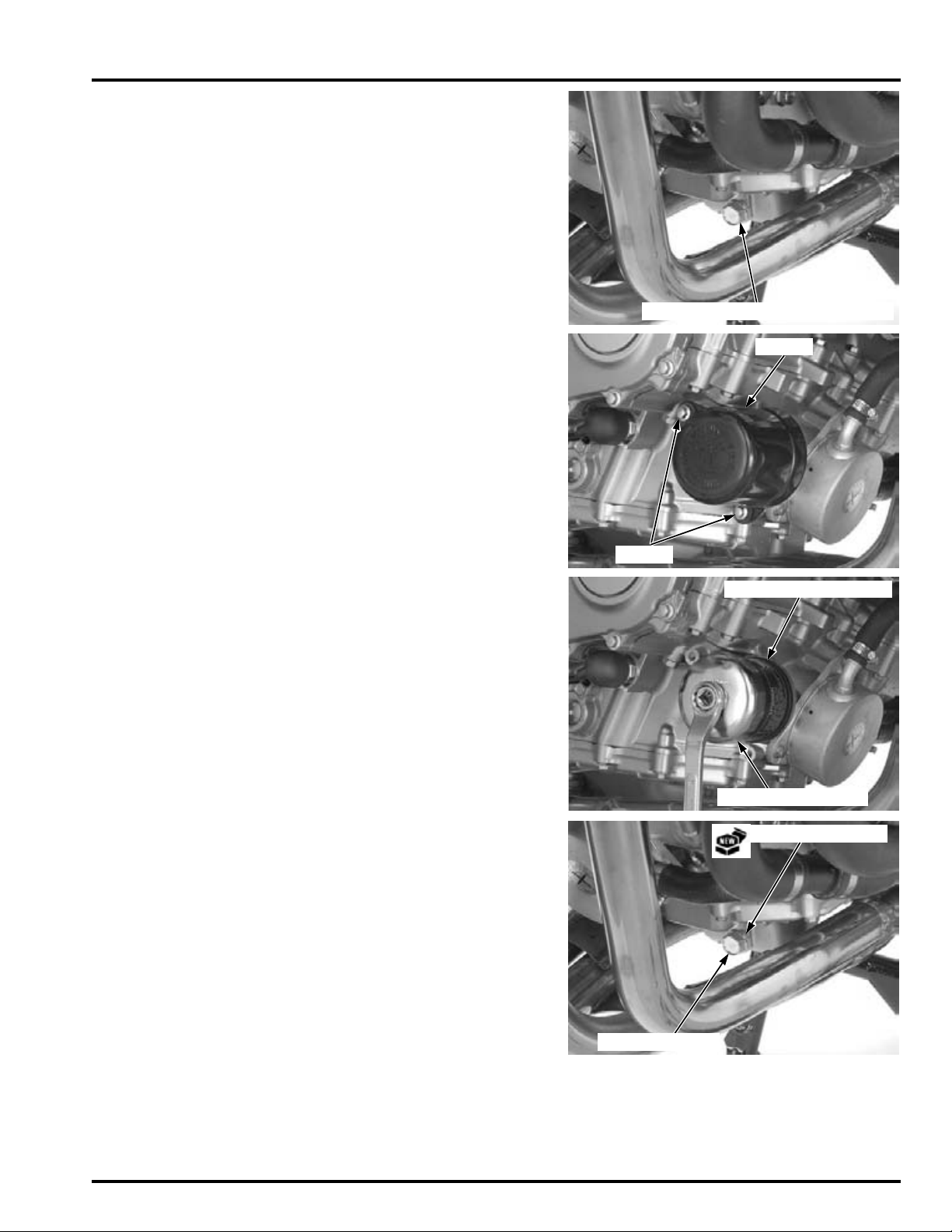
Remove the oil drain bolt and sealing washer, then
OIL DRAIN BOLT/SEALING WASHER
BOLTS
COVER
OIL FILTER WRENCH
OIL FILTER CARTRIDGE
SEALING WASHER
OIL DRAIN BOLT
drain the engine oil completely.
Remove the bolts and oil filter cover.
MAINTENANCE
Remove and discard the oil filter cartridge using the
special tool.
TOOL:
Oil filter wrench 07HAA-PJ70101
Replace the sealing washer with new one.
Install and tighten the oil drain bolt.
TORQUE: 30 N·m (3.1 kgf·m, 22 lbf·ft)
4-17
Page 82
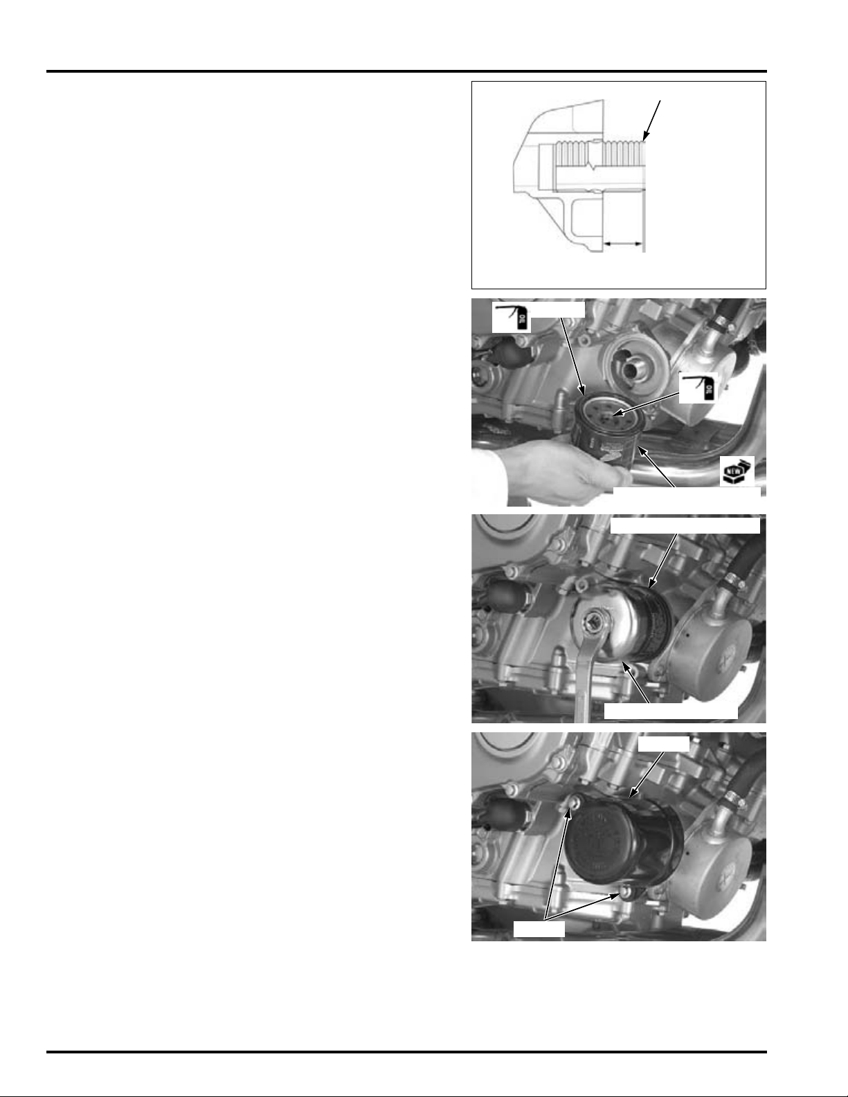
MAINTENANCE
14.4 – 15.4 mm
(0.57 – 0.61 in)
OIL FILTER BOSS
OIL FILTER CARTRIDGE
O-RING
OIL FILTER WRENCH
OIL FILTER CARTRIDGE
BOLTS
COVER
Check that the oil filter boss protrusion from the
crankcase is specified length as shown.
SPECIFIED LENGTH: 14.4 – 15.4 mm (0.57 – 0.61 in)
Apply clean engine oil to new oil filter cartridge
threads and O-ring.
Install the oil filter and tighten it to the specified
torque.
TOOL:
Oil filter wrench 07HAA-PJ70101
TORQUE: 26 N·m (2.7 kgf·m, 19 lbf·ft)
Install the oil filter cover and tighten the bolts
securely.
4-18
Page 83
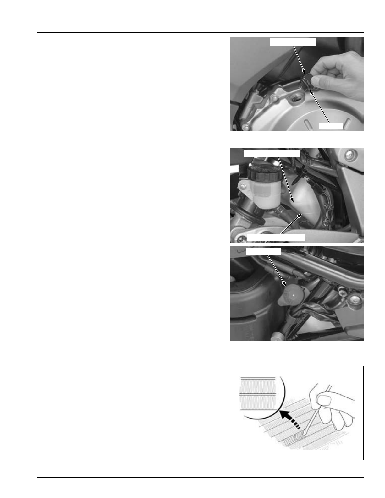
Fill the crankcase with recommended engine oil
OIL FILLER CAP
O-RING
UPPER LEVEL LINE
LOWER LEVEL LINE
FILLER CAP
(page 4-16).
OIL CAPACITY:
2.7 liter (2.9 US qt, 2.4 Imp qt) after draining
3.5 liter (3.7 US qt, 3.1 Imp qt) after oil filter change
Check that the O-ring on the oil filler cap is in good
condition, and replace it if necessary.
Install the oil filler cap.
Recheck the oil level (page 4-16).
Make sure there are no oil leaks.
RADIATOR COOLANT
Check the coolant level of the reserve tank with the
engine running at normal operating temperature.
The level should be between the "UPPER" and
"LOWER" level lines.
If necessary, add recommended coolant.
MAINTENANCE
COOLING SYSTEM
Remove the following:
– Seat (page 3-3)
– Left side cover (page 3-4)
Remove the reserve tank filler cap and fill to the
"UPPER" level line with 1:1 mixture of distilled water
and antifreeze.
RECOMMENDED ANTIFREEZE:
High quality ethylene glycol antifreeze containing
corrosion protection inhibitors.
Reinstall the filler cap.
Install the following:
– Left side cover (page 3-4)
– Seat (page 3-3)
Check the radiator air passages for clogging or damage.
Straighten bent fins, and remove insects, mud or
other obstructions with compressed air or low
water pressure.
Replace the radiator if the air flow is restricted over
more than 20% of the radiating surface.
4-19
Page 84
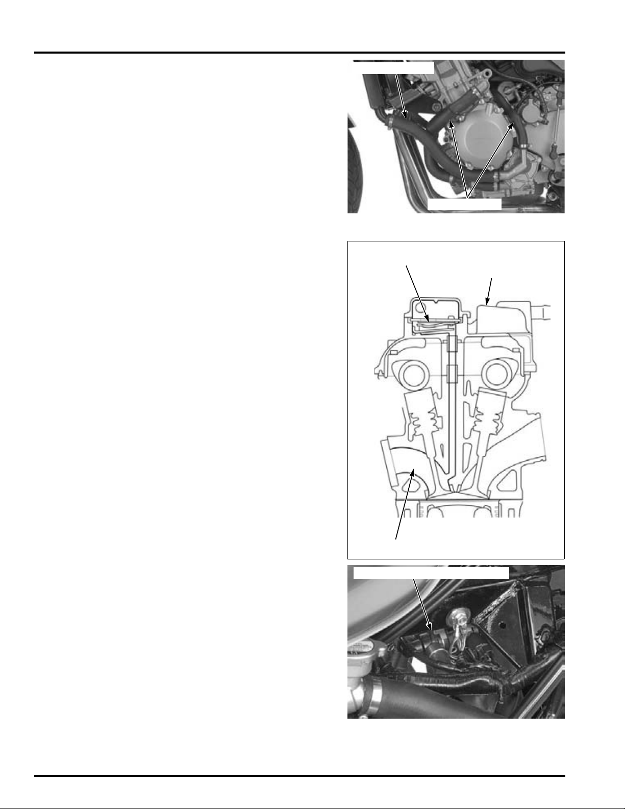
MAINTENANCE
RADIATOR HOSE
WATER HOSES
CYLINDER HEAD
COVER
PAIR CHECK VALVE
EXHAUST PORT
PAIR CONTROL SOLENOID VALVE
Inspect the radiator hoses for cracks or deterioration, and replace them if necessary.
Check the tightness of all hose clamps and fasteners.
SECONDARY AIR SUPPLY SYSTEM
• This model is equipped built-in secondary air
supply system. The pulse secondary air supply
system is located on the cylinder head cover.
• The secondary air supply system introduces filtered air into exhaust gases in the exhaust port.
The secondary air is drawn into the exhaust port
whenever there is negative pressure pulse in the
exhaust system. This charged secondary air promotes burning of the unburned exhaust gases
and changes a considerable amount of hydrocarbons and carbon monoxide into relatively harmless carbon dioxide and water.
If the hoses show
any signs of heat
damage, inspect
the reed valves in
the PAIR check
valves for damage.
4-20
Lift and support the fuel tank (page 4-5).
Check the PAIR (pulse secondary air injection) hoses
between the PAIR control solenoid valve and cylinder head cover for deterioration, damage or loose
connections. Make sure that the hoses are not
cracked.
Check the air suction hose between the air cleaner
housing and PAIR control solenoid valve for deterioration, damage or loose connections.
Make sure that the hoses are not kinked, pinched or
cracked.
Page 85
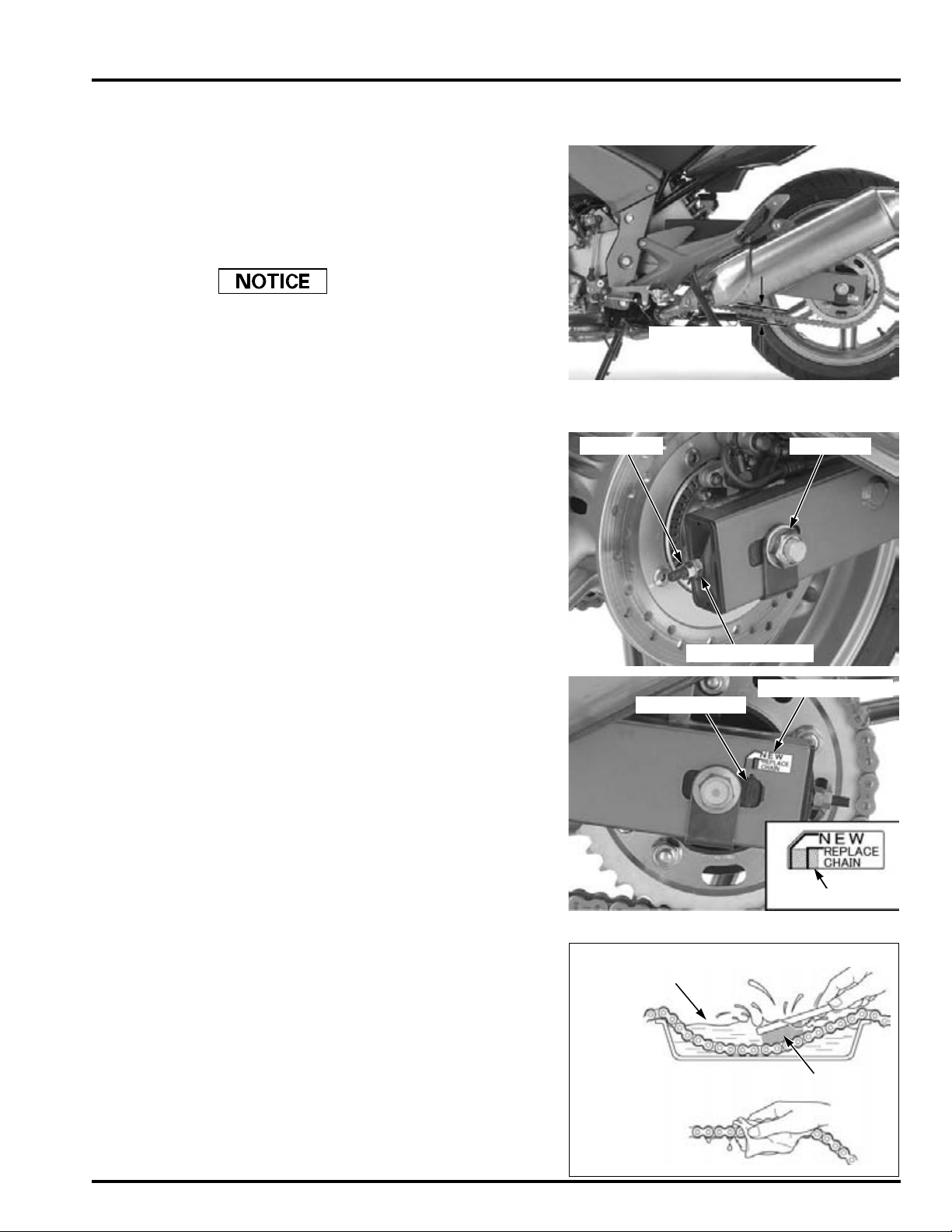
DRIVE CHAIN
20 – 30 mm
(4/5 – 1-1/5 in)
AXLE NUT
ADJUSTING NUT
LOCK NUT
INDICATOR LABEL
RED ZONE
ARROW MARK
Clean
Wipe and Dry
SOFT BRUSH
NON-FLAMMABLE OR HIGH
FLASH POINT SOLVENT
Never inspect and
adjust the drive
chain while the
engine is running.
DRIVE CHAIN SLACK INSPECTION
Turn the ignition switch OFF, place the motorcycle
on its side stand and shift the transmission into neutral.
Check the slack in the drive chain lower run midway
between the sprockets.
CHAIN SLACK: 20 – 30 mm (4/5 – 1-1/5 in)
Excessive chain slack, 50 mm (2.0 in) or more, may
damage the frame.
Lubricate the drive chain with #80 – 90 gear oil or
chain lubricant designed specifically for use with Oring chains. Wipe off the excess oil or chain lubricant.
ADJUSTMENT
Loosen the rear axle nut and both drive chain
adjuster lock nuts.
Turn both adjusting nuts an equal number of turns
until the correct drive chain slack is obtained.
A scale is included on the adjusters. Be sure the
reading on the scale is same for both sides.
Tighten the rear axle nut to the specified torque.
TORQUE: 108 N·m (11.0 kgf·m, 80 lbf·ft)
MAINTENANCE
Tighten each adjuster lock nut while holding the
adjusting nut.
TORQUE: 21 N·m (2.1 kgf·m, 15 lbf·ft)
Recheck the drive chain slack and free wheel rotation.
Check the index mark (arrow) on the left chain
adjuster.
If the index mark (arrow) reaches the red zone of the
wear indicator label, replace the drive chain with a
new one.
CLEANING AND LUBRICATION
Clean the chain with non-flammable or high flash
point solvent and wipe it dry.
Be sure the chain has dried completely before lubricating.
Inspect the drive chain for possible damage or wear.
Replace any chain that has damaged rollers, loose
fitting links, or otherwise appears unserviceable.
Installing a new chain on badly worn sprockets will
cause the new chain to wear quickly.
Inspect and replace sprocket as necessary.
4-21
Page 86
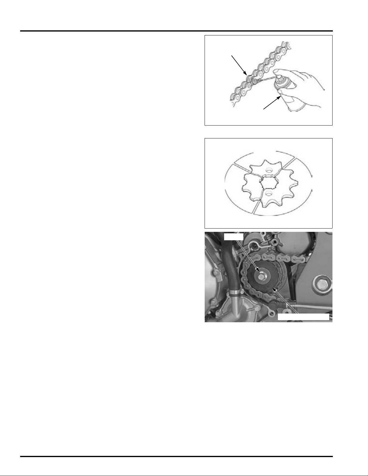
MAINTENANCE
#80 – 90 GEAR OIL OR
DRIVE CHAIN LUBRICANT
Lubricate
DAMAGE
WEAR
NORMAL
BOLT
DRIVE SPROCKET
Lubricate the drive chain with #80 – 90 gear oil or
drive chain lubricant designed specifically for use
with O-ring chains. Wipe off the excess oil or chain
lubricant.
SPROCKET INSPECTION
Remove the left crankcase rear cover (page 12-7).
Inspect the drive and driven sprocket teeth for wear
or damage, replace if necessary.
Never use a new drive chain on worn or damaged
sprockets.
Both chain and sprockets must be in good condition, or the new replacement chain will wear rapidly.
Check the attaching bolts and nuts on the drive and
driven sprockets.
If any are loose, torque them.
TORQUE:
Drive sprocket bolt:
54 N·m (5.5 kgf·m, 40 lbf·ft)
Final driven sprocket nut:
108 N·m (11.0 kgf·m, 80 lbf·ft)
4-22
Page 87
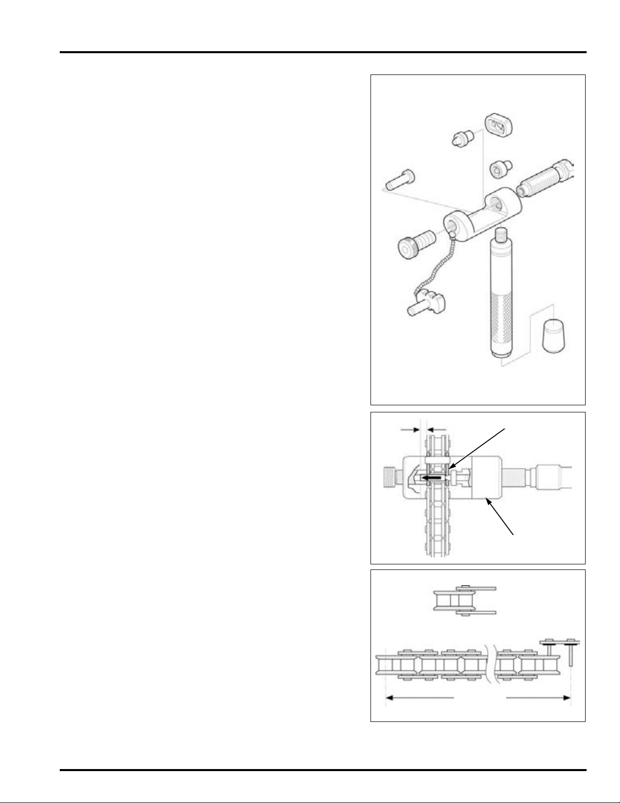
When using the
DRIVE CHAIN TOOL SET:
MASTER LINK
DRIVE CHAIN TOOL SET
120 LINKS
1 LINK
special tool, follow
the manufacturer's
instruction.
MAINTENANCE
REPLACEMENT
This motorcycle uses a drive chain with a staked
master link.
Loosen the drive chain (page 4-21).
Assemble the special tool as shown.
TOOL:
Drive chain tool set 07HMH-MR10103
Include the master
link when you
count the drive
chain links.
Locate the crimped pin ends of the master link from
the outside of the chain, and remove the link with
the drive chain tool set.
TOOL:
Drive chain tool set 07HMH-MR10103
Remove the drive chain.
Remove the excess drive chain links from the new
drive chain using the drive chain tool set.
STANDARD LINKS: 120 LINKS
REPLACEMENT CHAIN
DID: DID50VA8-120LE
RK: RK50HFOZ5-120LE
4-23
Page 88
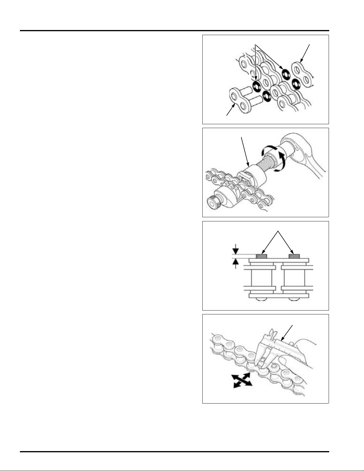
MAINTENANCE
O-RINGS
PLATE
MASTER LINK
DRIVE CHAIN TOOL SET
MASTER LINK PINS
SLIDE CALIPER
• Never reuse the old drive chain, master link,
Insert the master
link from the inside
of the drive chain,
and install the plate
with the
identification mark
facing the outside.
Assemble the new master link, O-rings and plate.
Assemble and set the drive chain tool set.
TOOL:
Drive chain tool set 07HMH-MR10103
master link plate and O-rings.
Make sure that the master link pins are installed
properly.
Measure the master link pin length projected from
the plate.
STANDARD LENGTH:
Stake the master link pins.
Make sure that the pins are staked properly by measuring the diameter of the staked area using a slide
caliper.
DIAMETER OF THE STAKED AREA:
DID: 1.15 – 1.55 mm (0.045 – 0.061 in)
RK: 1.2 – 1.4 mm (0.05 – 0.06 in)
DID: 5.50 – 5.80 mm (0.217– 0.228 in)
RK: 5.30 – 5.70 mm (0.209 – 0.224 in)
4-24
Page 89

MAINTENANCE
NO GOOD
GOOD
CRACKED
DRIVE CHAIN SLIDER
WEAR INDICATORS
"LOWER" LEVEL MARK
SIGHT GLASS
A drive chain with a
clip-type master link
must not be used.
After staking, check the staked area of the master
link for cracks.
If there is any cracking, replace the master link, Orings and plate.
DRIVE CHAIN SLIDER
Remove the left crankcase rear cover (page 12-7).
Inspect the drive chain slider for excessive wear or
damage.
If it is worn to the wear indicator, replace the drive
chain slider (page 15-15).
BRAKE FLUID
Spilled fluid can damage painted, plastic or rubber
parts. Place a rag over these parts whenever the
system is serviced.
• Do not mix different types of fluid, as they are
not compatible with each other.
• Do not allow foreign material to enter the system
when filling the reservoir.
When the fluid level is low, check the brake pads for
wear (page 4-26). A low fluid level may be due to
wear of the brake pads. If the brake pads are worn,
the caliper piston is pushed out, and this accounts
for a low reservoir level.
If the brake pads are not worn and the fluid level is
low, check entire system for leaks (page 4-27).
FRONT BRAKE
Turn the handlebar to the left so the reservoir is
level and check the front brake reservoir fluid level
through the sight glass.
4-25
Page 90

MAINTENANCE
CASTING LEDGE
"LOWER"
"UPPER"
RESERVOIR CAP
BOLT
WEAR LIMIT GROOVES
WEAR LIMIT GROOVE
If the fluid level is near the "LOWER" level mark,
remove the reservoir cap, set plate and diaphragm,
and fill the reservoir with DOT 4 brake fluid from a
sealed container to the casting ledge.
Install the diaphragm, set plate and reservoir cap,
and tighten the cap screws.
TORQUE: 1.5 N·m (0.2 kgf·m, 1.1 lbf·ft)
REAR BRAKE
Support the motorcycle upright on a level surface.
Check the fluid level in the rear brake reservoir.
If the level is near the "LOWER" level line, remove
the mounting bolt and the reservoir cap, and fill the
reservoir with DOT 4 brake fluid from a sealed container to the "UPPER" level line.
Install the reservoir cap with the diaphragm and set
plate.
Install the reservoir onto the frame and tighten the
mounting bolt.
TORQUE: 10 N·m (1.0 kgf·m, 7 lbf·ft)
BRAKE PAD WEAR
FRONT BRAKE PADS
Check the brake pads for wear.
Replace the brake pads if either pad is worn to the
wear limit groove.
For front brake pad replacement:
– CBF1000A (page 16-15)
– CBF1000 (page 16-16)
REAR BRAKE PADS
Check the brake pads for wear.
Replace the brake pads if either pad is worn to the
wear limit groove.
For rear brake pad replacement:
– CBF1000A (page 16-17)
– CBF1000 (page 16-18)
4-26
Page 91
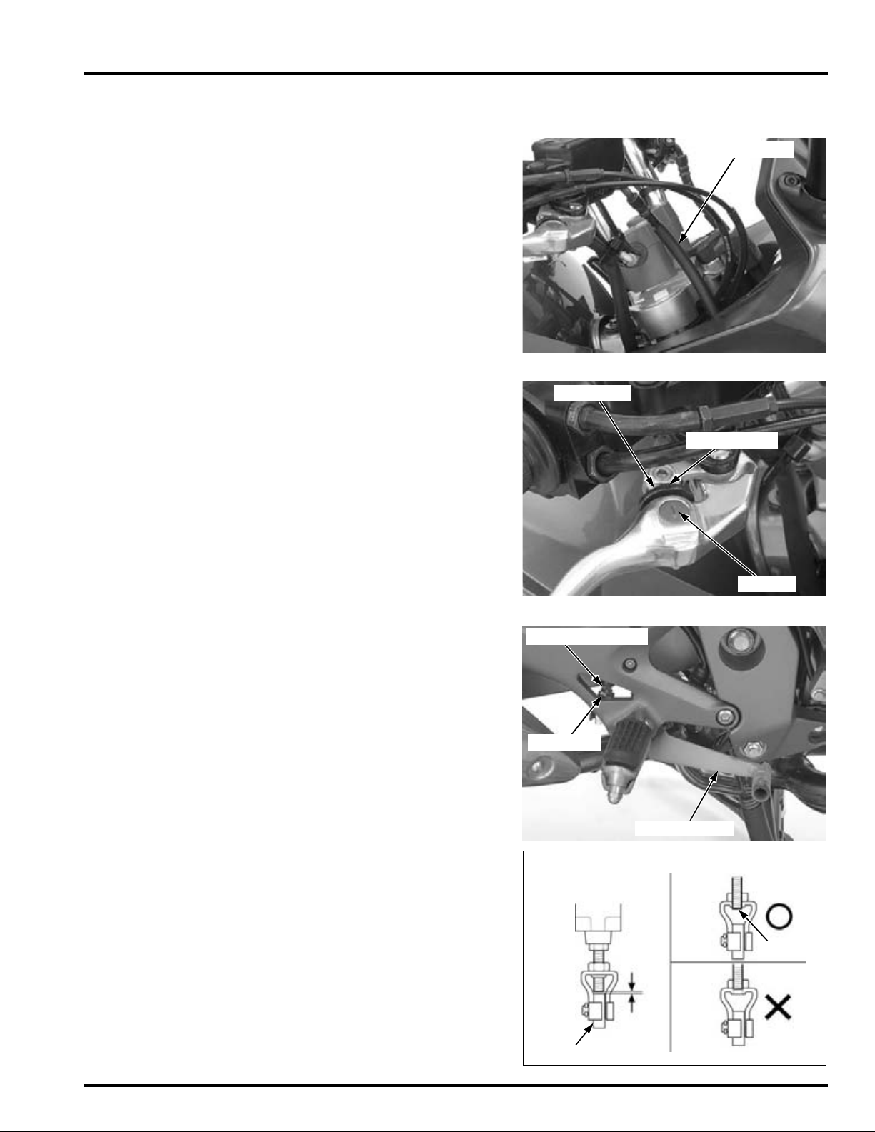
BRAKE SYSTEM
BRAKE HOSE
ADJUSTER
ARROW
INDEX MARK
LOCK NUT
BRAKE PEDAL
ADJUSTING BOLT
BRAKE PEDAL
LOWER POSITION: HIGHER POSITION:
THREAD
1 mm
(0.04 in)
INSPECTION
Firmly apply the brake lever or pedal, and check that
no air has entered the system.
If the lever or pedal feels soft or spongy when operated, bleed the air from the system.
Inspect the brake hose and fittings for deterioration,
cracks and signs of leakage.
Tighten any loose fittings.
Replace hoses and fittings as required.
Refer the procedure for brake bleeding:
– CBF1000A (page 16-7)
– CBF1000 (page 16-13)
BRAKE LEVER ADJUSTMENT
Align the index
mark on the
adjuster with the
arrow on the brake
The distance between the top of the brake lever and
the grip can be adjusted by turning the adjuster.
lever.
MAINTENANCE
BRAKE PEDAL HEIGHT ADJUSTMENT
Loosen the lock nut and turn the master cylinder
push rod to obtain the desired pedal height.
After adjustment, hold the adjusting bolt and
tighten the lock nut.
TORQUE: 17 N·m (1.7 kgf·m, 13 lbf·ft)
If the brake pedal is adjusted to the lower position,
make sure that the clearance between the lower end
of the push rod and the brake pedal does not fall
below 1 mm (0.04 in).
If the brake pedal is adjusted to the higher position,
make sure that the lower end of the push rod thread
is visible inside the joint.
4-27
Page 92
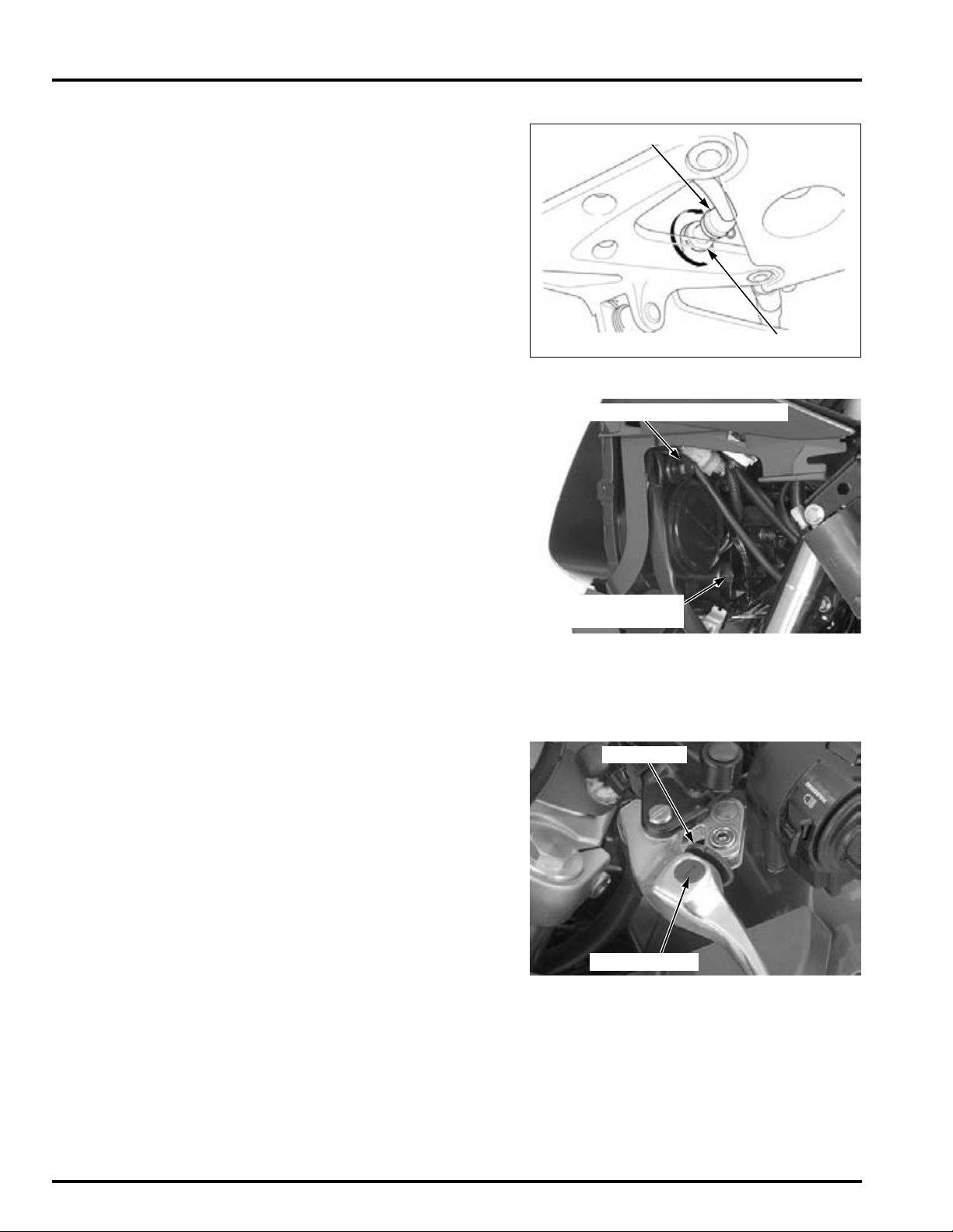
MAINTENANCE
BRAKE LIGHT SWITCH
ADJUSTER
VERTICAL BEAM ADJUSTING KNOB
HORIZONTAL BEAM
ADJUSTING SCREW
ADJUSTER
ARROW MARK
BRAKE LIGHT SWITCH
• The front brake light switch can not be adjusted.
Adjust the brake light switch so that the brake light
comes on just prior to the brake actually being
engaged.
If the light fails to come on, adjust the switch so that
the light comes on at the proper time.
Hold the switch body and turn the adjuster. Do not
turn the switch body.
HEADLIGHT AIM
Place the motorcycle on a level surface.
Remove the front right/left side cowls (page 3-6).
Adjust the headlight
aim as specified by
local laws and
regulations.
Left Headlight:
Right Headlight:
Adjust the headlight aim vertically by turning the
vertical beam adjusting knob.
A clockwise rotation moves the beam up and counterclockwise rotation moves the beam down.
Adjust the headlight aim horizontally by turning the
horizontal beam adjusting screw.
A clockwise rotation moves the beam toward the
right and counterclockwise rotation moves the
beam toward the left side of the rider.
A clockwise rotation moves the beam toward the
left and counterclockwise rotation moves the beam
toward the right side of the rider.
CLUTCH SYSTEM
CLUTCH LEVER ADJUSTMENT
Align the index
mark on the
adjuster with the
arrow on the brake
The distance between the tip of the clutch lever and
the grip can be adjusted by turning the adjuster.
lever.
4-28
Page 93
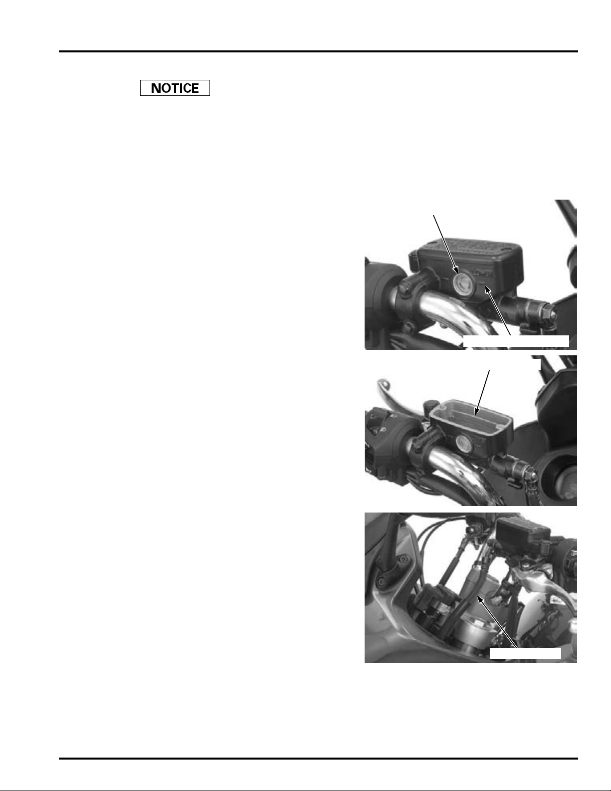
CLUTCH FLUID
"LOWER" LEVEL MARK
SIGHT GLASS
CASTING LEDGE
CLUTCH HOSE
Spilled fluid can damage painted, plastic or rubber
parts. Place a rag over these parts whenever the
system is serviced.
• Do not mix different types of fluid, as they are
not compatible with each other.
• Do not allow foreign material to enter the system
when filling the reservoir.
• When the fluid level is low, check entire system
for leaks.
Turn the handlebar to the right so that the reservoir
is level and check the clutch fluid level.
MAINTENANCE
If the fluid level is near the "LOWER" level mark,
remove the reservoir cap, set plate and diaphragm,
and fill the reservoir with DOT 4 brake fluid from a
sealed container to the casting ledge.
Install the diaphragm, set plate and reservoir cap,
and tighten the cap screws.
TORQUE: 1.5 N·m (0.2 kgf·m, 1.1 lbf·ft)
Firmly apply the clutch lever, and check that no air
has entered the system.
If the lever feels soft or spongy when operated,
bleed the air from the system.
Inspect the clutch hose and fittings for deterioration,
cracks and signs of leakage.
Tighten any loose fittings.
Replace hoses and fittings as required.
Refer the procedure for clutch fluid bleeding (page
10-6).
4-29
Page 94
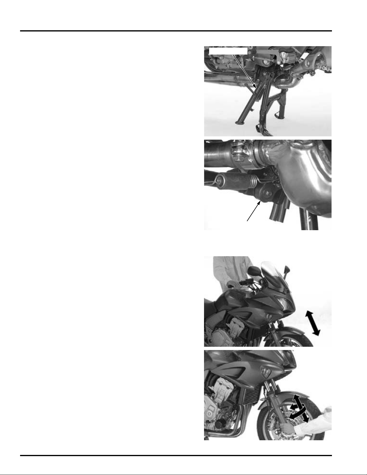
MAINTENANCE
SIDE STAND
SIDE STAND SWITCH
SIDE STAND
Support the motorcycle on a level surface using the
center stand (CBF1000A) or maintenance stand.
Check the side stand spring for damage or loss of
tension.
Check the side stand assembly for freedom of
movement and lubricate the side stand pivot if necessary.
Check the side stand ignition cut-off system:
1. Sit astride the motorcycle and raise the side
2. Start the engine with the transmission in neutral,
3. Move the side stand full down.
4. The engine should stop as the side stand is low-
If there is a problem with the system, check the side
stand switch (page 21-24).
stand.
then shift the transmission into gear, with the
clutch lever squeezed.
ered.
SUSPENSION
Loose, worn or
damaged
suspension parts
impair motorcycles
stability and
control.
FRONT SUSPENSION INSPECTION
Check the action of the forks by operating the front
brakes and compressing the front suspension several times.
Check the entire assembly for signs of leaks, damage or loose fasteners.
Replace damaged components which cannot be
repaired.
Tighten all nuts and bolts.
Refer to the fork service (page 14-19).
Check for worn steering stem bearings by grabbing
the front fork leg and attempting to move the front
fork side to side.
Replace the steering head bearings if any looseness
is noted.
4-30
Page 95
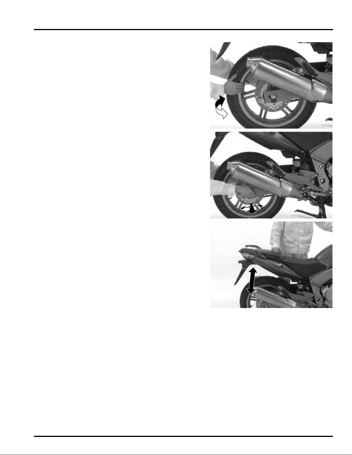
REAR SUSPENSION INSPECTION
Support the motorcycle securely and raise the rear
wheel off the ground.
Hold the swingarm and move the rear wheel side
ways with force to see if the axle bearings are worn.
Check for worn swingarm bearings by grabbing the
rear ends of the swingarm and attempting to move
the swingarm side to side.
Replace the bearings if any are looseness is noted.
MAINTENANCE
Check the action of the shock absorber by compressing it several times.
Check the entire shock absorber assembly for signs
of leaks, damage or loose fasteners.
Replace damaged components which cannot be
repaired.
Tighten all nuts and bolts.
Refer to the shock absorber service (page 15-13).
NUTS, BOLTS, FASTENERS
Check that all chassis nuts and bolts are tightened to
their correct torque values (page 1-13).
Check that all safety clips, hose clamps and cable
stays are in place and properly secured.
4-31
Page 96

MAINTENANCE
WHEELS/TIRES
Check the tires for cuts, embedded nails, or other
damage.
Check the wheel for trueness:
– Front wheel (page 14-13)
– Rear wheel (page 15-6)
Tire pressure should be checked when the tires are
COLD.
RECOMMENDED TIRE PRESSURE AND TIRE SIZE:
Tire pressure kPa
(kgf/cm
Tire size
Tire
bland
FRONT REAR
2
, psi)
Bridgestone
Michelin Pilot ROAD B Pilot ROAD A
250 (2.50, 36) 290 (2.90, 42)
120/70ZR17
M/C (58W)
BT57F
RADIAL U
160/60ZR17
M/C (73W)
BT57R
RADIAL E
Measure the tread depth at the center of the tires.
Replace the tires when the tread depth reaches the
following limits.
MINIMUM TREAD DEPTH:
FRONT: 1.5 mm (0.06 in)
REAR: 2.0 mm (0.08 in)
STEERING HEAD BEARINGS
Check that the control cables do not interfere with
handlebar rotation.
Support the motorcycle securely and raise the front
wheel off the ground.
Check that the handlebar moves freely from side to
side.
If the handlebar moves unevenly, binds, or has vertical movement, inspect the steering head bearings
(page 14-30).
4-32
Page 97
5. LUBRICATION SYSTEM
5
LUBRICATION SYSTEM DIAGRAM ·········· 5-2
SERVICE INFORMATION ··························· 5-3
TROUBLESHOOTING ································· 5-4
OIL PRESSURE INSPECTION····················· 5-5
OIL STRAINER/
PRESSURE RELIEF VALVE ························ 5-6
OIL PUMP ··················································· 5-8
OIL COOLER ············································· 5-12
5-1
Page 98
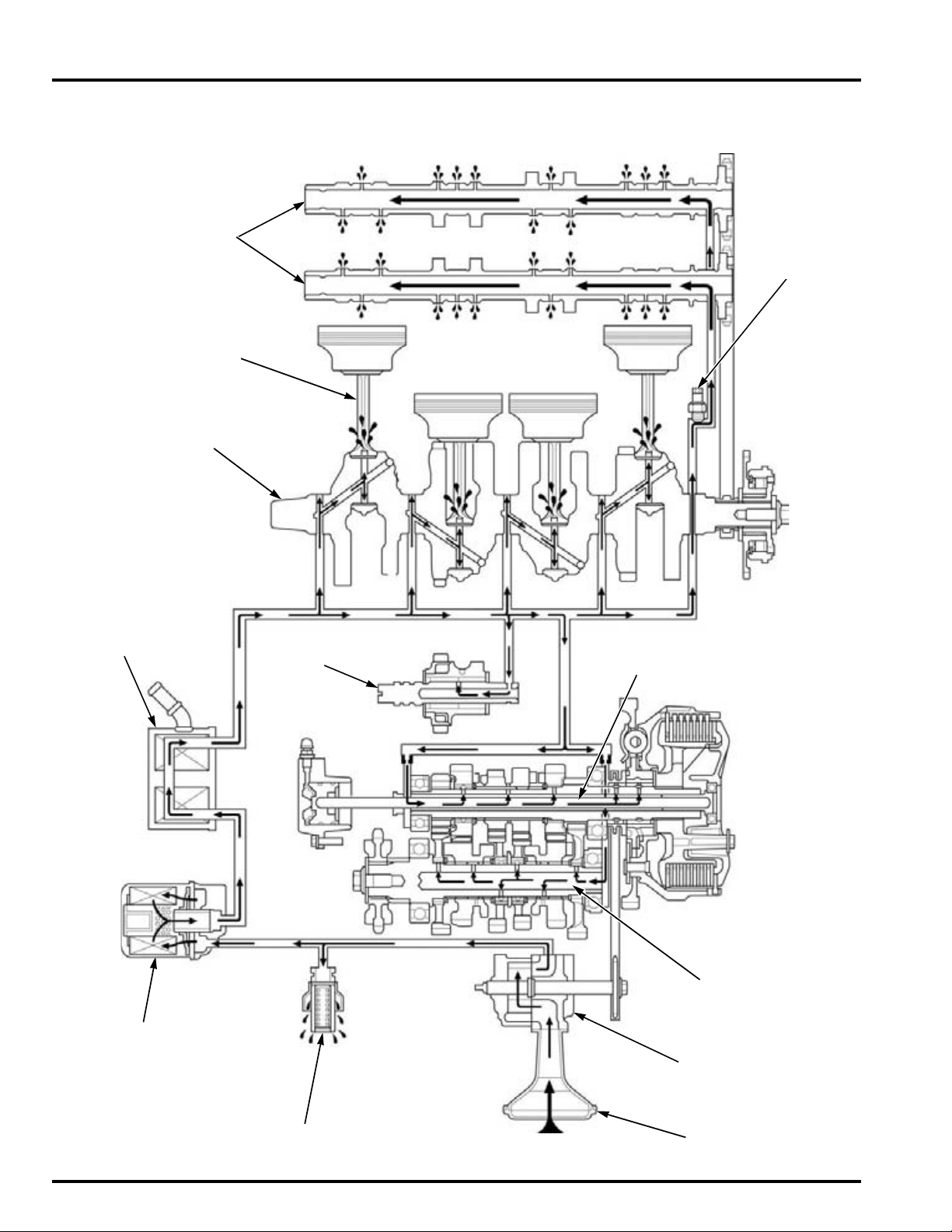
LUBRICATION SYSTEM
CAMSHAFTS
PISTON/
CONNECTING ROD
CRANKSHAFT
OIL FILTER CARTRIDGE
OIL STRAINER
OIL COOLER
OIL PRESSURE RELIEF VALVE
OIL PUMP
COUNTERSHAFT
MAINSHAFT
BALANCER
EOP SWITCH
LUBRICATION SYSTEM
LUBRICATION SYSTEM DIAGRAM
5-2
Page 99
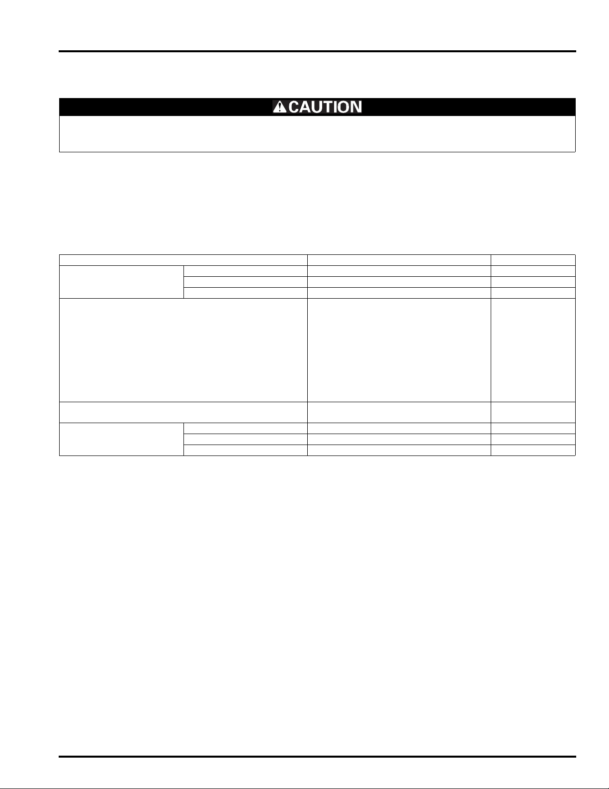
LUBRICATION SYSTEM
SERVICE INFORMATION
GENERAL
Used engine oil may cause skin cancer if repeatedly left in contact with the skin for prolonged periods. Although this is
unlikely unless you handle used oil on a daily basis, it is still advisable to thoroughly wash your hands with soap and
water as soon as possible after handling used oil.
• The oil pump can be serviced with the engine installed in the frame.
• The service procedures in this section must be performed with the engine oil drained.
• When removing and installing the oil pump, use care not to allow dust or dirt to enter the engine.
• If any portion of the oil pump is worn beyond the specified service limits, replace the oil pump as an assembly.
• After the oil pump has been installed, check that there are no oil leaks and that oil pressure is correct.
SPECIFICATIONS
Unit: mm (in)
ITEM STANDARD SERVICE LIMIT
Engine oil capacity After draining 2.7 liter (2.9 US qt, 2.4 lmp qt) –
After oil filter change 3.5 liter (3.7 US qt, 3.1 lmp qt) –
After disassembly 3.6 liter (3.8 US qt, 3.2 lmp qt) –
Engine oil Suggested oil: –
Honda "4-stroke motorcycle oil" or
an equivalent
Oil recommendation:
API classification: SG or higher
(except oils labeled as energy conserving on the circular API service
label)
Viscosity: SAE 10W-30
JASO T 903 standard: MA
Oil pressure at EOP (engine oil pressure) switch 510 kPa (5.2 kgf/cm
6,000 min
Oil pump Tip clearance 0.15 (0.006) 0.20 (0.008)
Body clearance 0.15 – 0.21 (0.006 – 0.008) 0.35 (0.014)
Side clearance 0.04 – 0.09 (0.002 – 0.004) 0.17 (0.007)
-1
(rpm)/(80°C/176°F)
2
, 74 psi) at
–
TORQUE VALUES
Oil pump assembly bolt 8 N·m (0.8 kgf·m, 5.9 lbf·ft) CT bolt
Oil pump driven sprocket bolt 15 N·m (1.5 kgf·m, 11 lbf·ft) Apply a locking agent to the threads.
5-3
Page 100

LUBRICATION SYSTEM
TOOLS
Oil pressure gauge set
07506-3000001
or equivalent commercially available.
Oil pressure gauge attachment
07406-0030000
or equivalent commercially available.
TROUBLESHOOTING
Oil level too low
• Oil consumption
• External oil leak
• Worn piston rings
• Improperly installed piston rings
• Worn cylinders
• Worn valve stem seals
• Worn valve guide
Low oil pressure
• Oil level low
• Clogged oil strainer
• Internal oil leak
• Incorrect oil being used
No oil pressure
• Oil level too low
• Oil pressure relief valve stuck open
• Broken oil pump drive chain
• Broken oil pump drive or driven sprocket
• Damaged oil pump
• Internal oil leak
High oil pressure
• Oil pressure relief valve stuck closed
• Clogged oil filter, oil cooler gallery or metering orifice
• Incorrect oil being used
Oil contamination
• Oil or filter not changed often enough
• Worn piston rings
Oil emulsification
• Blown cylinder head gasket
• Leaky coolant passage
• Entry of water
5-4
 Loading...