

Page 1
GPS Engine Board
M-90
SPECIFICATION
No. 1-1, Innovation Rd. I, Science-Based Industrial Park, HsinChu City 300, Taiwan R.O.C
(300) 新竹科學工業園新竹縣創新一路 1-1 號
TEL: 03-6687000 FAX: 03-6687111
Website: www.holux.com
Version :1.2
All Right Reserved
Page 2

M-90
GPS Module series
Version Change History
THE PRO NAME IN GPS
Version
0.1 2007/04/18 Draft release
0.2 2007/05/18 Add 5. reference design
1.0 2007/06/27 Official release, modify dimension and reference design
1.1 2007/07/05 Modify current, tracking current:< 45mA
1.2 2009/07/27 Modify V_BAT power
Date Revised Reason
HOLUX Technology, Inc.
No. 1-1, Innovation Rd. I, Science-Based Industrial Park, HsinChu City 300, Taiwan R.O.C
TEL: 886-3-6687000 FAX:886-3-6687111 E-mail:info@holux.com.tw http:www.holux.com.tw
- 2 -
Page 3

M-90
GPS Module series
THE PRO NAME IN GPS
Index
1. Introduction.............................................................................................4
1.1 General introductions.................................................................4
1.2 Key Features................................................................................4
1.3 Applications.................................................................................4
2 Technical Description.............................................................................5
2.1 Block Diagram .............................................................................5
2.2 Pin Definition ...............................................................................5
2.3 Specification................................................................................6
3. Mechanical Dimension ...........................................................................8
3.1 Mechanical Dimension................................................................8
4 Package ...................................................................................................9
4.1 Packing ........................................................................................9
4.2 Reference product photo..........................................................10
5 User Interface........................................................................................ 11
5.1 Protocol...................................................................................... 11
5.2 NMEA Protocol .......................................................................... 11
5.3 MTK NMEA Packet Format ....................................................... 12
6 Reference design.................................................................................. 13
6.1 Application circuit.....................................................................13
6.2 Reference PCB pattern ............................................................. 14
6.3 Recommendation reflow profile...............................................15
HOLUX Technology, Inc.
No. 1-1, Innovation Rd. I, Science-Based Industrial Park, HsinChu City 300, Taiwan R.O.C
TEL: 886-3-6687000 FAX:886-3-6687111 E-mail:info@holux.com.tw http:www.holux.com.tw
- 3 -
Page 4

M-90
GPS Module series
1.
Introduction
THE PRO NAME IN GPS
1.1 General introductions
M-90 is an ultra miniature 12 * 12.2 * 2.2 mm GPS engine board
designed by low power consumption MTK GPS solution. It provides
superior sensitivity up to -159dBm and fast Time-To-First-Fix in
navigation application. The stable performance of M-90 is your best
choice to be embedded in your portable device design, like PDA、PND、
mobile phone、Digital Camera for GPS service.
1.2 Key Features
‧ Small form factor: 12 * 12.2 * 2.2 mm
‧ RoHS/WEEE compliant
‧ High sensitivity -159dBm
‧ Searching up to 32 Channel of satellites
‧ Fast Position Fix
‧ Low power consumption
‧ RTCM-in ready.
‧ Built-in WAAS/EGNOS/MSAS Demodulator.
‧ Support NMEA0183 V 3.01 data protocol.
‧ Real time navigation for location based services.
‧ For Car Navigation, Marine Navigation, Fleet Management, AVL and
Location-Based Services, Auto Pilot, Personal Navigation or touring
devices, Tracking devices/systems and Mapping devices application
1.3 Applications
‧ Automotive and Marine Navigation
‧ Automotive Navigator Tracking
‧ Emergency Locator
‧ Geographic Surveying
‧ Personal Positioning
‧ Sporting and Recreation
‧ Embedded applications:
‧ Smart phone, UMPC, PND, MP4
HOLUX Technology, Inc.
No. 1-1, Innovation Rd. I, Science-Based Industrial Park, HsinChu City 300, Taiwan R.O.C
TEL: 886-3-6687000 FAX:886-3-6687111 E-mail:info@holux.com.tw http:www.holux.com.tw
- 4 -
Page 5
M-90
GPS Module series
2 Technical Description
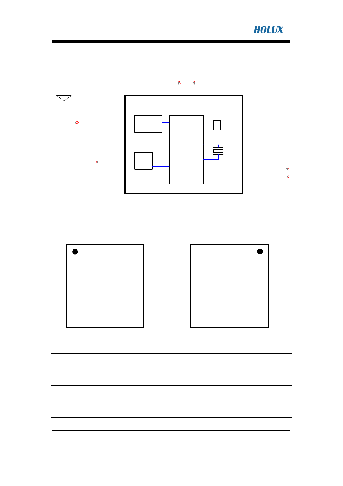
2.1 Block Diagram
THE PRO NAME IN GPS
Pass ive Ant enna or Active Antenna
LNA
POWER_IN
2.2 Pin Definition
P1
NEMA_OUTPUT SETT ING_IN
SAW
Filiter
MTK
GPS CHIP
Analog
LDO
Digital
M90 Engine Board
P16
P16
UART_RXUART_TX
TCXO
RTC
GPIO
TIME_MARK
GPS Fix Ind ication
1PPS_OUTPUT
P1
P2
P3
P4
P5
P6
P7
P8
Top view Button view
Pin Pin Name Type
1
2
3
4
5
6
VDD
PPS
TXD0
RXD0
HRST
GPIO6/S0
I 3.3 ~ 5 V supply input for main power
O 1 Hz pulse 10% duty cycle when GPS has position fix
O Serial Data Output A
I Serial Data input A
I GPS reset, active low
I/O General purpose I/O,SPI data output
P15
P14
P13
P12
P11
P10
P9
P15
P14
P13
P12
P11
P10
P9
M-90 MAIN Rev: 01
2007.06.26
Function description
P2
P3
P4
P5
P6
P7
P8
HOLUX Technology, Inc.
No. 1-1, Innovation Rd. I, Science-Based Industrial Park, HsinChu City 300, Taiwan R.O.C
TEL: 886-3-6687000 FAX:886-3-6687111 E-mail:info@holux.com.tw http:www.holux.com.tw
- 5 -
Page 6

M-90
GPS Module series
7
GPIO7/SIN
I/O General purpose I/O,SPI data output
THE PRO NAME IN GPS
8
9
10
11
12
13
14
15
16
17
18
GND
GND
RF_IN
GND
GPIO5/SCS0
GPIO/SCK
GPIO0/GPS
status
PWR_EN
V_BAT
GND
GND
2.3 Specification
G Ground
G Ground
I GPS signal input, 2.85 VDC output
G Ground
I/O General purpose I/O,SPI chip select 0
I/O General input / output, SPI clock
O GPS status, blink when GPS has position fix General input/output
I Power enable/active high
I RTC and backup SRAM power Input:
Backup Battery : 2.6 ~ 3.6 V (use battery)
DC Input:3.3~5.0V (use VDD)
G Ground
I Ground
General
GPS technology MT3318 GPS chipset
Frequency L1,1575.42MHz
C/A Code 1.023MHZ chip rate
Channels 32 channels all in view searching
Sensitivity Better than -159dBm
Receiver Accuracy
(Follow MTK chip specification)
Without aid:3.0 M 2D-RMS
Position
DGPS(WAAS, EGNOS, MSAS, RTCM):2.5 M
Velocity Without aid:0.1M/sec
Time 0.1 µs. Sync GPS time
Datum
Datum WGS84(Default) total 219 datum’s
Time to First Fix
(Follow MTK chip specification)
Hot start 1 sec average
Warm start 33 sec average
Cold start 36 sec average
Reacquisition
Protocol
HOLUX Technology, Inc.
No. 1-1, Innovation Rd. I, Science-Based Industrial Park, HsinChu City 300, Taiwan R.O.C
TEL: 886-3-6687000 FAX:886-3-6687111 E-mail:info@holux.com.tw http:www.holux.com.tw
<1sec
- 6 -
Page 7

M-90
GPS Module series
NMEA0183(v3.1)GGA(1),GLL(1),GSA(1),GSV(5),RMC(1),
THE PRO NAME IN GPS
GPS Output Data
VTG(1)
Support Baud rate 4800/9600/…./115200 bps (default
4800), Data bit:8,Stop bit:1, No parity.
Update Rata
1Hz(default)
Protocol Support NMEA-0183
1PPS
Limitations
Acceleration Limit
Altitude Limit
Velocity Limit
Enable(1Hz pulse 10% duty cycle)
(Follow MTK chip specification)
<4G
<18000 meters
<515 M/sec
Jerk Limit 20 M/sec3
Power
Operation Current Acquisition:65mA@3.3V
Operation Current
Tracking:<45mA@3.3V
VDD: 3.3~5.0V
DC Input Range
V_BAT:3.3~5.0V
Processing Core
Processor Type ARM7EJ-S
Processor Speeds 48 MHz
Integrated program
Flash
Interface CMOS 2.85 V Level
Temperature
Operating Temperature
Storage Temperature
Operating Humidity
Physical
Dimension
Weight 1g.
4 M bits
-40℃ to +85℃.
-40℃ to +85℃.
5% to 95%,No condensing
12 * 12.2 * 2.2 mm.
HOLUX Technology, Inc.
No. 1-1, Innovation Rd. I, Science-Based Industrial Park, HsinChu City 300, Taiwan R.O.C
TEL: 886-3-6687000 FAX:886-3-6687111 E-mail:info@holux.com.tw http:www.holux.com.tw
- 7 -
Page 8

M-90
GPS Module series
3. Mechanical Dimension
3.1 Mechanical Dimension
THE PRO NAME IN GPS
HOLUX Technology, Inc.
No. 1-1, Innovation Rd. I, Science-Based Industrial Park, HsinChu City 300, Taiwan R.O.C
TEL: 886-3-6687000 FAX:886-3-6687111 E-mail:info@holux.com.tw http:www.holux.com.tw
- 8 -
Page 9

M-90
GPS Module series
4 Package
4.1 Packing
THE PRO NAME IN GPS
Tray dimension: 325*220*9 mm, Standard Content Qty: 100 pcs.
Carton dimension: 340*235*120 mm,Standard Content Qty: 2,000 pcs.
HOLUX Technology, Inc.
No. 1-1, Innovation Rd. I, Science-Based Industrial Park, HsinChu City 300, Taiwan R.O.C
TEL: 886-3-6687000 FAX:886-3-6687111 E-mail:info@holux.com.tw http:www.holux.com.tw
- 9 -
Page 10

M-90
GPS Module series
THE PRO NAME IN GPS
4.2 Reference product photo
The photo is for reference, the real content will depend on the real
configuration.
Top side:
Bottom side:
HOLUX Technology, Inc.
No. 1-1, Innovation Rd. I, Science-Based Industrial Park, HsinChu City 300, Taiwan R.O.C
TEL: 886-3-6687000 FAX:886-3-6687111 E-mail:info@holux.com.tw http:www.holux.com.tw
- 10 -
Page 11

M-90
GPS Module series
THE PRO NAME IN GPS
5 User Interface
M-90 provides 2-wire digital UART port for communication of GPS position
data using NMEA protocol or MTK extension protocol. UART port is capable of
4800 to 115200 baud rate.
5.1 Protocol
M-90 is default to support standard NMEA-0183 protocol. In addition, a series
of MTK extensions (PMTK messages) have been developed that can be used
to provide extended capabilities common to many applications
5.2 NMEA Protocol
M-90 is capable of supporting following NMEA formats:
NMEA RECORD Description
GGA GPS fix data
GLL Geographic
GSA GNSS DOP and active satellite
GSV GNSS Satellites in view
Recommended minimum specific
RMC
GNSS data
Course Over Ground and Ground
VTG
Speed
ZDA Time&Data
HOLUX Technology, Inc.
No. 1-1, Innovation Rd. I, Science-Based Industrial Park, HsinChu City 300, Taiwan R.O.C
TEL: 886-3-6687000 FAX:886-3-6687111 E-mail:info@holux.com.tw http:www.holux.com.tw
- 11 -
Page 12

M-90
used to tell the decoder how
GPS Module series
THE PRO NAME IN GPS
5.3 MTK NMEA Packet Format
Preamble TalkerID PktType Datafield * CHK1 CHK2 CR LF
Maximum packet length is restricted to 255 bytes
Field Length Type D
Preamble 1 byte Character “$”
TalkerID 4 byte Character string “PMTK”
“000”to “999”, an identifier
PktType 3 byte Character string
to decode the packet
“, ”must be inserted ahead
DataField Variable
* 1 byte Character
CHK1
2 byte Character string
CHK2
CR, LF 2 byte Binary data
each data filed to help the
decoder process the Data
Field
The star symbol is used to
mark the end of Data Field
checksum of the data
between Preamble “, ”and
“*”
used to identify the end of a
packet
HOLUX Technology, Inc.
No. 1-1, Innovation Rd. I, Science-Based Industrial Park, HsinChu City 300, Taiwan R.O.C
TEL: 886-3-6687000 FAX:886-3-6687111 E-mail:info@holux.com.tw http:www.holux.com.tw
- 12 -
Page 13

M-90
GPS Module series
6 Reference design
6.1 Application circuit
Block3
4
5
6
GPS_FIX
12
D2
AMBER-D0603
12
R9
240-R0402
C3
1 2
C0402C020CB
Block2 Block4
3V
12
R3
10-R0402
R1
0-R0402
R2
0-R0402
12
R4
47R0402
3V
12
D1
ASD751V
R7
470-R0402
BT1
1PPS
3V
U1
R5
10-R0402
1
1 2
TX-1
RX1
12
C6
C0402B104KP
12
C7
C0402B104KP
TX1
RX1
12
C11
C0402B104KP
VDD
2
1PPS
3
TXD0
4
RXD0
5
HRST
GPIO0/GPS STATUS
6
GPIO6/SO
7
GPIO7/SIN
8
GND
9
GND
M-90 Module
U3 SP3223EEA-SSOP20
2
C1+
4
C1-
5
C2+
6
C2-
13
T1_TTL
12
T2_TTL
15
R1_TTL
10
R2_TTL
EN1INVALID
14
ON
20
OFF
GND
GND
V_BAT
PWR_EN
GPIO8/SCK
GPIO5/SCSO
GND
RF_IN
VCC
V+
V-
T1_232
T2_232
R1_232
R2_232
GND
19
3
7
17
8
16
9
11
18
18
17
16
15
14
13
12
11
10
C0402C8R2CB
3V
5V.
1 2
1 2
1 2
C1
1 2
R11
1 2
75-R0402
C8
C0402B104KP
C0402B104KP
C9
C10 C0402B104KP
GPS_FIX
12
L1
39nH-L0402
VCC_5V
12
R6
10-R0402
DB9/90D/F
1
6
2
7
3
8
4
9
5
10 11
1 2
2
1
12
C0402B102KB
J3
MS621FL11E-BAT
R8
47-R0402
U2
OUT3GS
GND
GND
VCC
IN
BGA428
C2
THE PRO NAME IN GPS
3V
R10
0-R0402
Bloc k1
C4
1 2
12
C0402C040CB
L2
3.3nH-L0402
1
L3
39nH-L0402
C5
12
C0402B104KP
32
J1
RF_IN1
U1: Holux M-90 GPS Module.
U2: BGA428, which is a GaAs MMIC Low Noise Amplifier(LNA). For good
receiving sensitivity, a low noise amplifier with 19dB gain and 1.8dB noise
figure is suggested to designed in mother board or active antenna.
U3:Silicon Labs SP3223EEA, which is a RS232 IC.
J1: Connector for passive or external antenna.
R1,R2,R10: 0Ω
R3,R6,R5: 10Ω
R4,R8:47Ω
L1,L3: 39nH
L2:3.3nH
C1:8.2pF
C2:102pF
C3:2pF
C4:4pF
Block1: The LNA environment parameter is possibly different between M-90
and the mainboard, please notice and fine tune if possible.
Block2: User can supply the low power to pin “HRST” if you want to reset GPS,
or keep the pin as “pull high” or “floating” in operating.
HOLUX Technology, Inc.
No. 1-1, Innovation Rd. I, Science-Based Industrial Park, HsinChu City 300, Taiwan R.O.C
TEL: 886-3-6687000 FAX:886-3-6687111 E-mail:info@holux.com.tw http:www.holux.com.tw
- 13 -
Page 14

M-90
GPS Module series
THE PRO NAME IN GPS
Block3: User can supply the high power to pin “PWR_EN” to enable module or
supply the low power to pin “PWR_EN” to disable module.
Block4: For user’s convenience, M-90 sends the signal once per second from
1pps pin, The output is a CMOS 2.8V positive level signal which is
synchronous with GPS time within 1 microsecond of bias. Only upon the
situation of tracking or navigating it will output.
6.2 Reference PCB pattern
HOLUX Technology, Inc.
No. 1-1, Innovation Rd. I, Science-Based Industrial Park, HsinChu City 300, Taiwan R.O.C
TEL: 886-3-6687000 FAX:886-3-6687111 E-mail:info@holux.com.tw http:www.holux.com.tw
- 14 -
Page 15

M-90
GPS Module series
THE PRO NAME IN GPS
6.3 Recommendation reflow profile
1. We strongly recommend that this module should be designed to mount on
top side of motherboard with main chip together which process the final
reflow.
2. The maximum frequency of this module to pass reflow process should be
no more than twice, including repair operation, otherwise it may cause side
effect to the performance.
3. Below is the recommend reflow profile referred to Main chip MT3318.
HOLUX Technology, Inc.
No. 1-1, Innovation Rd. I, Science-Based Industrial Park, HsinChu City 300, Taiwan R.O.C
TEL: 886-3-6687000 FAX:886-3-6687111 E-mail:info@holux.com.tw http:www.holux.com.tw
- 15 -
 Loading...