

Page 1
HOLUX Wireless GPS Receiver M-215 User’s Manual
Holux
GPS Receiver
M-215
1F, No. 30, R&D Rd. II, HsinChu City 300, Science-based Industrial Park, Taiwan
User’s Guide
OCT 2007
Rev.A
Technology, Inc.
TEL: 886-3-6687000 FAX: 886-3-6687111
Website: www.holux.com
All Rights Reserved
Page 2
HOLUX Wireless GPS Receiver M-215 User’s Manual
2
Page 3

HOLUX Wireless GPS Receiver M-215 User’s Manual
3
Page 4

HOLUX Wireless GPS Receiver M-215 User’s Manual
Table of Contents
1. Overview----------------------------------------------------------------------------------------5
2. Packing List------------------------------------------------------------------------------------5
3. Main features---------------------------------------------------------------------------------- 6
4. Specification----------------------------------------------------------------------------------- 7
5. Product Overview-----------------------------------------------------------------------------8
6. Configuration-----------------------------------------------------------------------------------9
7. Physical Dimension--------------------------------------------------------------------------9
8. Output terminal and definition----------------------------------------------------------10
9. Optional accessory cable-----------------------------------------------------------------11
10. Driver Installation----------------------------------------------------------------------------13
10.1 System Requirement-----------------------------------------------------------------------13
10.2 Installation-------------------------------------------------------------------------------------14
11. Installation of Mini GPS Viewer program--------------------------------------------15
12. Execute the Mini GPS Viewer program-----------------------------------------------15
13. Warranty-----------------------------------------------------------------------------------------17
14. Troubleshooting------------------------------------------------------------------------------17
Federal Communications Commission (FCC) Statement------------------------------18
4
Page 5

HOLUX Wireless GPS Receiver M-215 User’s Manual
1. Overview
The HOLUX M-215 GPS Receiver provides a easy-to-use trip guiding tool. You are
able to enjoy a brand new experience in driving with GPS Receiver. It can support
USB or RS232 (PS2 connector) cable connection via, it’s more convenient and
flexible.
Enjoy the GPS life!
z Applications :
* Vehicle tracing & Location base services
* PDA/Notebook navigation
* Car navigation
* Marine navigation
* Distance measurement
* Sports and Recreation
* Fleet Management
* Vehicle Tracking
2. Packing List
Thank you for purchasing the M-215 GPS Receiver. Before you start, make sure
that the following items are included in your package. If any of these items are missing,
please contact your original local HOLUX dealer or distributor.
1. M-215 GPS receiver 1 Set
2. Suction Cup, 40mm 1 Set
3. Velcro, 18*123mm 1 Set
4. User guide and Driver CD 1 Pcs
5. M-215 Quick guide 1 Pcs
6. Warranty card 1 Pcs
Option accessory: refer to section 9.
5
Page 6

HOLUX Wireless GPS Receiver M-215 User’s Manual
3. Main features
1. Built in MTK Low power consumption GPS chipset.
2. 32 parallel satellite-searching channels for fast acquisition and
reacquisition.
3. Superior sensitivity up to -159 dBm.
4. Built-in WAAS/EGNOS/MSAS Demodulator without any additional
hardware.
5. Low power consumption.
6. Support NMEA0183 V 3.01 data protocol.
7. 1 LED indicate to shows the GPS status of device.
8. For Car navigation, Marine navigation, Fleet management, AVL, Personal
navigation, Tracking System, and Mapping device application.
9. Water proof design for industry standard IPX7.
10. Support OS :Windows 98/2000/XP/Vista
.
6
Page 7

HOLUX Wireless GPS Receiver M-215 User’s Manual
4. Specification
•Search up to 32 satellites
•Receiver : L1, 1575.42 MHz
•C/A code:1.023 MHz
•Update rate: 1 Hz.
•Antenna type : Built in patch antenna
Specifications
Positioning
•Minimum signal tracked : -159dBm
•Dimension: 64.5 × 42 × 17.8 mm.
•Weight: < 84g.
•Waterproof: IPX7
•Operation temperature : -10 ℃ to + 60 ℃
•Store temperature : -20 ℃ to + 70 ℃
•Operation humidity : 5% to 95% no condensing
◆ Non DGPS (Differential GPS):
•Position : 3.0 M CEP excluding SA
•Velocity: 0.1M / sec.
•Interval: 0.1 µs to Sync GPS
◆ DGPS (EGNOS/WAAS/MSAS):
•Position: < 2.2 M., Horizontal deviation 95% time
< 5 M., Vertical deviation 95 % time
*The above data is based on the specifications of the MTK GPS chip
•Time to reposition < 0.1 sec average
Positioning
Timing
Protocol and
Interface
•Hot start 1 sec
•Warm start 33 sec
•Cold start 36 sec
*The above data are based on specifications of the MTK GPS chip
◆Output terminal: USB (CMOS Level) or RS232
•NMEA protocol output : V 3.01
Baud rate : 4800 bps
Data bit : 8
Parity : N
Stop bit : 1
7
Page 8

HOLUX Wireless GPS Receiver M-215 User’s Manual
•Output format :
Standard : GPGGA (1time/1 sec), GPGSA (1 time/5 sec.),
GPGSV (1time /5 sec.), GPRMC (1time /1 sec.),
GPVTG (1 time/1 sec).
Optional : GLL, or MTK NMEA Command.
•Altitude: Max 18,000 M (60,000 feet)
Physical
Specifications
Led
Function
•Velocity: Max 515 M./sec ( 1000 knots)
•Acceleration: Max 4G
•Vibration: 20 M/ second
GPS status
5. Product Overview
M-215 Body description see below:
LED of GPS (Orange)
3
, Max.
LED status :
COLOR STATUS DESCRIPTION
Light on Acquiring Satellites
Orange
Blinking 1 time / 1 sec Position Fixed
8
Page 9

HOLUX Wireless GPS Receiver M-215 User’s Manual
6. Configuration
Type Connector Type
U USB Connector
R RS232 (PS2 Female connector)
7. Physical Dimension
Type U : (Unit : mm)
Type R : (Unit : mm)
9
Page 10

HOLUX Wireless GPS Receiver M-215 User’s Manual
8. Output terminal and definition
Type U :
Output terminal: USB connector
Pin definition:
Pin Signal Name
1 +5V
2 D +
3 D -
4 Ground
Type R :
Output terminal: RS232 (PS2 Female connector)
Pin definition:
10
Page 11

HOLUX Wireless GPS Receiver M-215 User’s Manual
Pin Signal
1 Tx
2 +5VDC
3 N.C.
4 Ground
5 N.C.
6 Rx
9. Optional accessory cable
The M-215 includes an antenna in a unique style waterproof gadget. Simply
connect USB connector or PS-2 female connector to one of the accessories linking to
your notebook PC, PDA or other devices. The one-piece cigarette adapter allows you
to connect M-215 to your PDA. Optional accessory cables and output connector are
listed and described below:
Type Name Function description
1 CA-RS232 Convertible cable, Comport, 5VDC input.
2 CA-6V30V High power connector, 6-30VDC
3 A-20005 12V-26V Cigarette Adapter /Charger
11
Page 12

HOLUX Wireless GPS Receiver M-215 User’s Manual
I. Type 1 CA-RS232: DB 9 pins Female and PS-2 male connector:
Cable Length to M-215: 1 meter
RS-232 to PS-2: 45 cm
DB 9 pins Female connector function definition:
Pin Signal Name
1 N.C
2 Tx
3 Rx
4 N.C
5 Ground
6 N.C
7 N.C
8 N.C
9 DGPS in
N.C = No connection
PS2 composite male connector function definition:
12
Page 13

HOLUX Wireless GPS Receiver M-215 User’s Manual
Pin Signal Name
1 +5V
2 N.C
3 N.C
4 Ground
5 N.C
6 N.C
N.C = No connection
II. Type 2 CA-6V30V: High power connector
III. Type 3 Car Cigarette Adapter and PDA connector
The optional cigarette adapter is with 2-meter cable for using in a car or boat.
Input voltage: DC12V - 26V
Black
Red +6~30VDC
Green Tx
10. Driver Installation
Color Signal
Ground
10.1 System Requirement
CPU: IBM, Pentium II or above, or other compatible PC.
Memory: above 32 MB
System: Windows 98/2000/XP/VISTA
13
Page 14

HOLUX Wireless GPS Receiver M-215 User’s Manual
10.2 Installation
I. Starts the driver installer from driver CD.
II. Connect M-215 to computer. System will search new hardware and install
the driver automatically.
III. Install the USB driver “CP210x_VCP_Win2K_XP.exe ” from the CD provided
in the package.
IV. Click <Start> menu, select → <Setting>, then enter→ <Controller>
V. After entering <Controller>, and select <System>.
VI. Select <Device Manager>.
VII. Find the < Connector (COM & LPT)> and check the Virtual COM Port,
which was created by the USB driver.
* Please note that the virtual COM port
number might be different on every
computer. Before using navigation software,
please confirm the COM Port numbers
created by your computer and provided by
your navigation software. Otherwise, the
navigating software won’t receive the
satellite signal, because of the un-match
COM Port setting.
14
Page 15

HOLUX Wireless GPS Receiver M-215 User’s Manual
10. Installation of Mini GPS Viewer program
We provide the program “Mini GPS viewer.exe” for end users to watch the
satellite signal receiving status on laptop or PDA devices.
For Windows 2000/XP OS, you can execute “Mini GPS viewer_PC” directly.
For Microsoft Pocket PC, please copy “Mini GPS viewer_PPC” to the SD card or
device, and then execute “Mini GPS viewer_PPC”.
11. Execute the Mini GPS Viewer program
1. The following window is shown after executing Mini GPS Viewer_PPC,
(see Fig. 1). The Windows 2000/XP version is has a slightly different
display.
(Fig. 1)
2. Setup the Baud rate: 4800, then tap the “Scan” button to scan your COM
15
Page 16

HOLUX Wireless GPS Receiver M-215 User’s Manual
Port. Select your COM Port respectively, and then tap the “Open GPS”
button. Check log screen below to verify that the satellite data is receiving
correctly.
(Fig. 2)
3. Select “GPS Status” panel to observe the GPS information status, see
Fig. 3.
(Fig. 3)
16
Page 17

HOLUX Wireless GPS Receiver M-215 User’s Manual
4.
In the “setup” panel you can see “Hot Start” “Warm Start” “Cold Start”,
which allow you to re-acquisition the Ephemeris and Almanac. Basically,
the satellites are always moving in the sky, if Ephemeris and Almanac
data in the GPS Logger can’t meet real satellites status or if the GPS
Logger has been powered off for over 0.5 hours but you are no longer in
the previous position, then it will take more time for the GPS Logger to
obtain a GPS position fix. We suggest that you click “Cold Start” or “Warm
start” to re-acquisition.
、、
12. Warranty
The M-215 is guaranteed to be free from defects in material and functions for a
period of one year from the date of purchase. Any failure of this product within this
period, under normal operation conditions, will be repaired at no charge to the
customers.
13. Troubleshooting
Problems Possible Reasons Methods
No GPS’s CN
value output
but GPS timer
is counting
Cannot open
the COM port
Weak or no GPS signal at the
place of
Connection interrupted or COM
port is conflicted/occupied by other
programs.
M-215
Test under an open sky at a fixed location
and run the Mini GPS Viewer “Cold start”
function.
Check the connection again,
Check and close other programs that
might conflict with.
17
Page 18

HOLUX Wireless GPS Receiver M-215 User’s Manual
Federal Communications Commission (FCC)
Statement
This equipment has been tested and found to comply with the limits for a Class B
digital device, pursuant to Part 15 of the FCC Rules. These limits are designed to
provide reasonable protection against harmful interference in a residential installation.
This equipment generates, uses and can radiate radio frequency energy and, if not
installed and used in accordance with the instructions, may cause harmful
interference to radio communications. However, there is no guarantee that
interference will not occur in a particular installation. If this equipment does cause
harmful interference to radio or television reception, which can be determined by
turning the equipment off and on, the user is encouraged to try to correct the
interference by one of the following measures:
- Reorient or relocate the receiving antenna.
- Increase the separation between the equipment and Logger.
- Connect the equipment into an outlet on a circuit different from that
to which the Logger is connected.
- Consult the dealer or an experienced radio/TV technician for help.
CAUTION: Any changes or modifications not expressly approved by the party
responsible for compliance could void the user's authority to operate this equipment.
This device complies with Part 15 of the FCC Rules. Operation is subject to the
following two conditions: (1) This device may not cause harmful interference, and (2)
this device must accept any interference received, including interference that may
cause undesired operation.
This equipment must be installed and operated in accordance with provided
instructions and the antenna(s) used for this transmitter must be installed to provide a
separation distance of at least 20 cm from all persons and must not be co-located or
operating in conjunction with any other antenna or transmitter. End-users and
installers must be provided with antenna installation instructions and transmitter
operating conditions for satisfying RF exposure compliance.
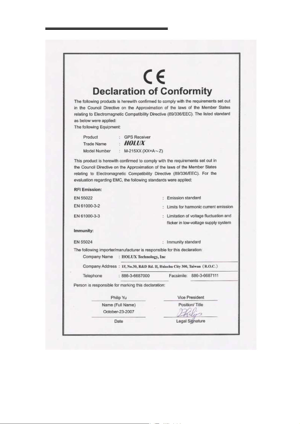
This equipment is in compliance with the essential requirements and other relevant
provisions of Directive 1999/5/EC.
18
 Loading...