

Page 1
SERVICE MANUAL
WS-P213 Hobart Water Softening
System Installation Instructions
WS-P213
- NOTICE -
This Manual is prepared for the use of trained Hobart Service
Technicians and should not be used by those not properly
qualified.
This manual is not intended to be all encompassing. If you have
not attended a Hobart Service School for this product, you should
read, in its entirety, the repair procedure you wish to perform to
determine if you have the necessary tools, instruments and skills
required to perform the procedure. Procedures for which you do
not have the necessary tools, instruments and skills should be
performed by a trained Hobart Service Technician.
The reproduction, transfer, sale or other use of this Manual,
without the express written consent of Hobart, is prohibited.
This manual has been provided to you by ITW Food Equipment
Group LLC ("ITW FEG") without charge and remains the property
of ITW FEG, and by accepting this manual you agree that you will
return it to ITW FEG promptly upon its request for such return at
any time in the future.
A product of Hobart Service 701 S. Ridge Ave Troy, OH 45374
F25312 Rev. A (0913)
Page 2

WS-P213 Hobart Water Softening System Installation Instructions
TABLE OF CONTENTS
INSTALLATION ............................................................................................ 3
INSTALLATION WS-P213 .............................................................................. 3
DISC REPLACEMENT ...................................................................................... 7
DISC REPLACEMENT WS-P213 ....................................................................... 7
DISC SELECTION .......................................................................................... 9
DISC SELECTION WS-P213 ............................................................................ 9
© HOBART SERVICE 2013
F25312 Rev. A (0913) Page 2 of 10
Page 3
WS-P213 Hobart Water Softening System Installation Instructions - INSTALLATION
INSTALLATION
INSTALLATION WS-P213
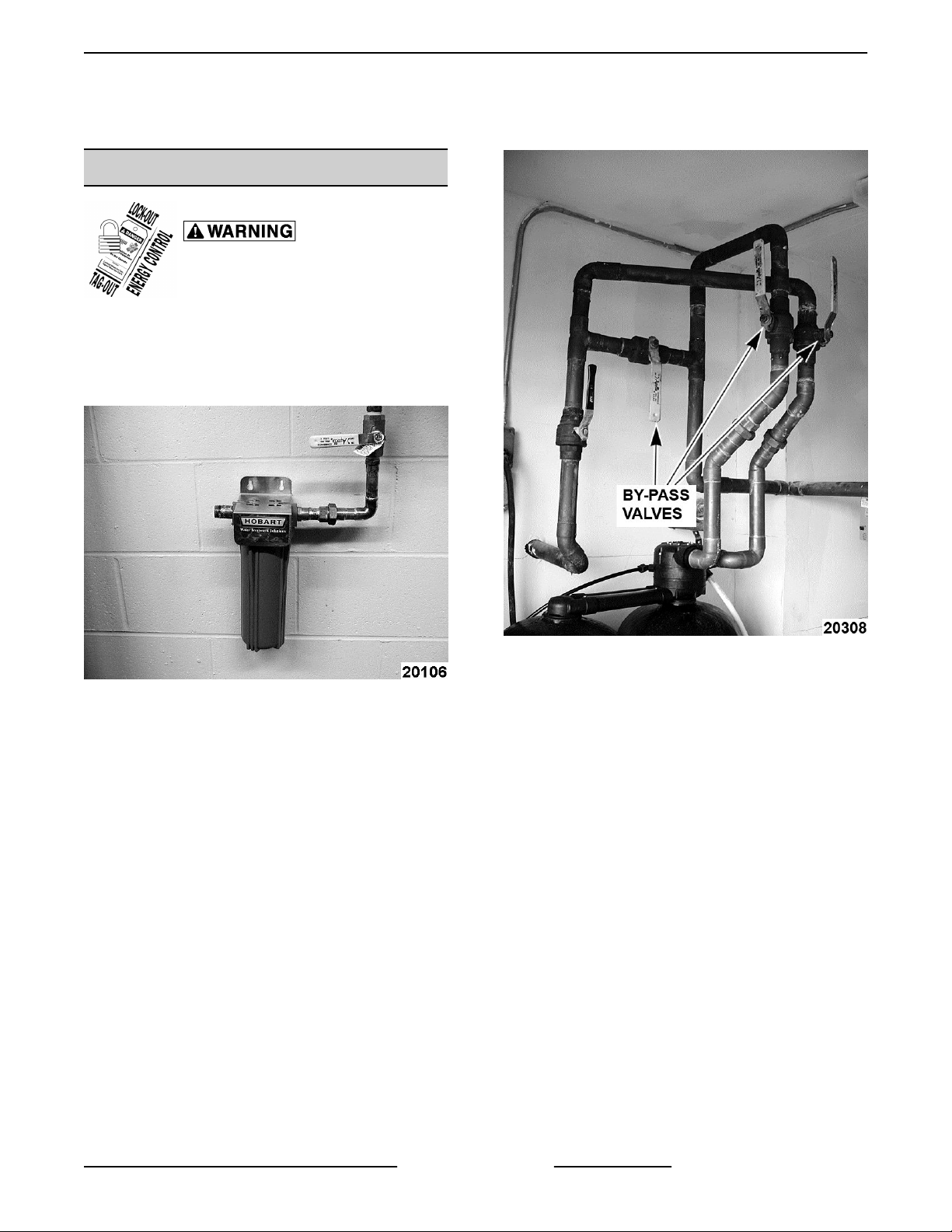
Disconnect the
electrical power to the machine and
follow lockout / tagout procedures.
1. Determine location to install equipment. Make
sure the unit will be on a flat surface.
2. If sand, silt, or turbidity is present, install a
separate prefilter.
Fig. 1
3. Install by-pass valving. Be certain to note the inlet
and outlet arrows on the valve head.
4. Connect the inlet/outlet adapters leading to the
softener using the proper size plumbing.
5. Plumb as necessary to accommodate the bypass
valve and to complete the installation.
NOTE: Actual installation of by-pass valving may vary
from installation to installation. Be sure to follow state
and local codes.
Fig. 2
NOTE: When installing a plastic component in line, it
is recommended that grounding straps be put in place
before the lines are actually cut to ensure the ground
is never broken.
NOTE: Do not solder brass adapters while inserted
in the module base. Damage to plastic and rubber
parts may result due to the heat. In addition, the
materials used in the soldering process may attack
certain types of plastics.
NOTE: Care should be taken during the installation
process to assure that solder and flux do not come in
contact with the media tanks, the control module, and
related components.
6. After all plumbing is completed, but before
connecting equipment, flush both the inlet and
outlet lines by opening the by-pass valve and
allowing water to rinse out any debris in the lines.
7. Locate enclosed kit containing four O-rings, two
pipes with O-rings, and the silicone packet. Apply
a liberal amount of silicone to the four Orings, and
the O-rings in the two pipes. Install the four Orings on the inlet/outlet adapters.
Page 3 of 10 F25312 Rev. A (0913)
Page 4

WS-P213 Hobart Water Softening System Installation Instructions - INSTALLATION
8. Connect the main tank with softener valve to the
inlet/outlet adapter. The inlet/outlet adapter is
inserted into the control valve and locked in place
by the plastic E-clips.
NOTE: Be certain the E-clips are fully inserted into
the valve. Check to make sure that all three tabs on
the E-clips are fully inserted.
9. Connect the remote tank to the main tank using
connector pipes, connector links and connector
pins.
Fig. 3
NOTE: Always use both links and pins.
10. Run a drain line to the discharge point.
NOTE: Follow state and local codes.
11. Before connecting unit, check for obstructions or
kinks. Apply Teflon tape to pipe threads on side
of softener valve, and install the two fittings
supplied. Connect drain line to valve.
NOTE: An air gap must be provided for all drain lines.
Check state and local plumbing codes for proper setup
of drain line air gaps.
NOTE: On drain lines that must travel more than 8
feet up and 30 feet over, it is best to take the 5/8" drain
line that fits the valve and attach it in a larger diameter
line or pipe.
12. Position the brine drum.
Fig. 4
NOTE: In Hobart Softeners, the brine drum mixes and
stores a solution of salt or potassium chloride for
regeneration of the softener media. During the brine
rinse cycle, this solution is drawn from the brine drum
and through the media to regenerate it. The brine
drum contains an adjustment to draw the correct
amount of salt or potassium chloride solution for each
cycle. This adjustment is made in two places, the
adjuster tube and the float cup.
NOTE: The adjuster tube measures the amount of
solution that is drawn from the brine drum into the
softener during the brine rinse cycle. The float cup
height determines how much softened water flows
back into the brine drum to prepare for the next
regeneration. The adjuster tube is set by cutting and
removing tabs on both sides of the tube. Cut across
each tab horizontally, following the channel in the
plastic. Break off each tab individually until the proper
setting is reached. The remaining number or letter
imprinted on the tab determines the correct setting.
F25312 Rev. A (0913) Page 4 of 10
Page 5

WS-P213 Hobart Water Softening System Installation Instructions - INSTALLATION
Fig. 5
NOTE: The float cup height determines how much
softened water flows back into the brine drum to
prepare for the next regeneration. The float cup is set
by adjusting its height above the bottom of the Brine
Valve Assembly. By removing the brine valve
assembly and resting it on a flat surface, the height of
the float cup can be measured with a ruler. The height
is measured from the base of the brine valve assembly
to the top of the float cup.
NOTE: Standard settings are defined by markings on
the rod of the brine valve assembly. Where the
predefined settings are not adequate, the actual float
cup height must be measured and the setting must be
measured and set according to the measured float cup
height.
Fig. 6
NOTE: Determining the correct brine valve setting for
a particular application is a three step process:
13. Determine the compensated hardness. This
requires a hardness test and an iron test on raw
water at the application site. Compensated
hardness is calculated by multiplying the ferrous
iron (in ppm) by 3 and adding it to the grains of
hardness.
14. To test the water supply, use the water analysis
test kit available through Pro Products Inc. The
recommended kit is #2401 Field Analysis Kit. To
order the test kit contact Pro Products at 800285-9176 or visit www.ProProducts.com.
15. Determine the salt setting. The salt setting is
determined by taking the compensated hardness
from Step 13 and using the specifications table
from DISC SELECTION WS-P213.
Page 5 of 10 F25312 Rev. A (0913)
Page 6

WS-P213 Hobart Water Softening System Installation Instructions - INSTALLATION
16. Determine adjuster tube and float cup settings.
Use Brine Valve Settings for WS-P213: 24 x 40
Brine Valve Adjustment to determine the correct
settings for both the adjuster tube and the float
cup height.
Brine Valve Settings for WS-P213: 24 x 40 Brine
Valve Adjustment
Salt Setting 15 lbs. 25 lbs.
Adjuster Tube 1.25 K
Float Cup 10.5" 12"
NOTE: Do not drop the brine valve into the drum.
Dropping may lower the float cup, resulting in an
improper setting. After the adjustments have been
made to the adjuster tube and the float cup, the brine
valve assembly must be installed in the brine drum.
Locate the brine valve in the brine well so the 3/8" bent
tube is along the back of the brine well away from the
brine drum wall. The 3/8" bent tube snaps into a notch
and extends from the brine drum about 1 inch.
17. Determine the correct number disc by referring to
DISC SELECTION WS-P213
18. To install disc refer to DISC REPLACEMENT
WS-P213
F25312 Rev. A (0913) Page 6 of 10
Page 7

WS-P213 Hobart Water Softening System Installation Instructions - DISC REPLACEMENT
DISC REPLACEMENT
DISC REPLACEMENT WS-P213
1. To change disc, remove screws and cap cover
from level one
Fig. 9
4. Remove meter drive pawl.
Fig. 7
2. Remove balance piston.
Fig. 8
3. Remove balance piston o-ring and balance
piston spring.
Fig. 10
5. Remove meter disc.
Fig. 11
Page 7 of 10 F25312 Rev. A (0913)
Page 8

WS-P213 Hobart Water Softening System Installation Instructions - DISC REPLACEMENT
6. Install correct meter disc and reassemble in
reverse order.
NOTE: Make certain all components are correctly
installed.
NOTE: Be certain to start cap screws by hand rotating
backwards until screw drops into thread then tighten.
An alternating, crossing pattern should be used while
tightening cap screws to ensure correct cap fit. Add a
clean grade of salt at this time. Higher grades of
Pelletized Salt for impurities and solubility should be
used.
NOTE: Do not use rock salt or solar salt.
NOTE: On iron-bearing water, a salt that contains
resin cleaning additives is recommended.
7. Open the inlet valve slowly and allow the tanks to
fill slowly with water. Water will run at the drain
until unit is full and pressurized.
8. With the unit in service and under pressure, allow
the brine drum to fill with water until the brine
valve shuts off.
9. After the unit is fully pressurized, purge air form
the lines by opening soft water outlet.
NOTE: When brine drum overflow could cause
damage, a ½" I.D. overflow line must be installed on
the barbed overflow fitting on drum and connected to
a drain. Make sure drain is not higher than barbed
fitting. FOLLOW STATE AND LOCAL CODES
10. Check for plumbing leaks.
11. Check unit for proper operation.
F25312 Rev. A (0913) Page 8 of 10
Page 9

WS-P213 Hobart Water Softening System Installation Instructions - DISC SELECTION
DISC SELECTION
DISC SELECTION WS-P213
Using the full louver nozzle, the amount of hardness removed (in compensated gpg) will be based on the amount
of brine and the meter disc selected.
Specifications
Salt usage / generation 15 lbs. 25 lbs.
Capacity 60,000 grains 70,000 grains
Efficiency 4,000 gr./lb. 2,800 gr./lb.
Dosing 6.0 lbs./cu. ft. 10.0 lbs./cu. ft.
Float cup setting 10.5" 12"
Specifications
Salt usage / generation 15 lbs. 25 lbs.
Capacity 60,000 grains 70,000 grains
Efficiency 4,000 gr./lb. 2,800 gr./lb.
Dosing 6.0 lbs./cu. ft. 10.0 lbs./cu. ft.
Float cup setting 10.5" 12"
WS-P213 Overdrive
Operation
WS-P213 Alternating
Operation
WS-P213 Overdrive Operation
WS-P213 Alternating Operation
WS-P213 Disc Selection Overdrive Operation
Disc Number 1 2 3 4 5 6 7 8
Compensated Hardness @ 15
lbs.*
Compensated Hardness @ 25
lbs.
Peak flow during regeneration 28.0 28.0 28.0 20.7 15.7 12.4 10.0 8.3
* Compensated hardness in gpg = Hardness + (3 x Fe in mg/l)
Disc Number 1 2 3 4 5 6 7 8
Compensated Hardness @ 15
lbs.*
Compensated Hardness @ 25
lbs.
Flow during regeneration (@
15 psig)
Gallons/Regeneration: 8,922 4,461 2,974 2,231 1,784 1,487 1,275 1,115
* Compensated hardness in gpg = Hardness + (3 x Fe in mg/l)
5 10 14 17 21 25 30 35
6 12 16 20 24 30 35 40
WS-P213 Disc Selection Alternating Operation
6 12 18 24 30 35 40 45
7 14 21 28 34 40 45 51
20 20 20 20 15.7 12.4 10.0 8.3
Page 9 of 10 F25312 Rev. A (0913)
Page 10

WS-P213 Hobart Water Softening System Installation Instructions - DISC SELECTION
F25312 Rev. A (0913) Page 10 of 10
 Loading...