

INSTALLATION
INSTRUCTIONS & PARTS
HOBART
COMPACT WATER SOFTENER
WS-55
A product of HOBART TROY, OHIO 45374
F25407 (February 2011)
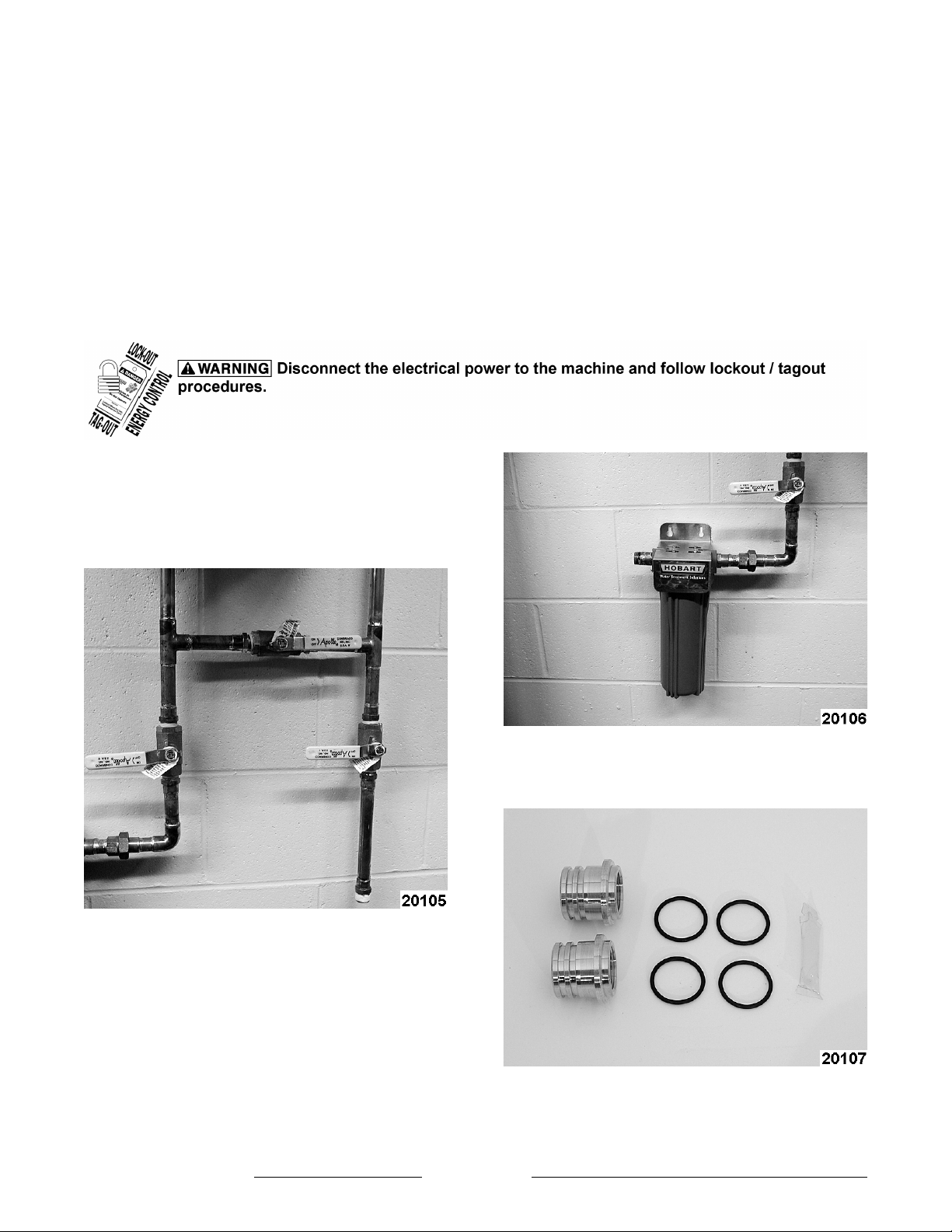
TABLE OF CONTENTS
INSTALLATION ............................................................................ 2
DISC SELECTION .......................................................................... 9
REPLACEMENT PARTS .................................................................... 10
© HOBART 2011
INSTALLATION
SAVE THESE INSTRUCTIONS
1. Locate cold water supply line and appropriate
drains for softener installation.
NOTE: WS-55 is designed to operate from a cold
water supply only.
2. Install by-pass valving.
3. Install prefilter if needed.
4. Remove all items from shipping package.
5. Locate brass in/out adapters, 4 O-rings, and
silicone seal lube.
6. Locate connector hose and output hose from
F25407 (February 2011) Page 2 of 16
Selecto filter. Apply 2 to 3 wraps of Teflon tape
to the male threads.
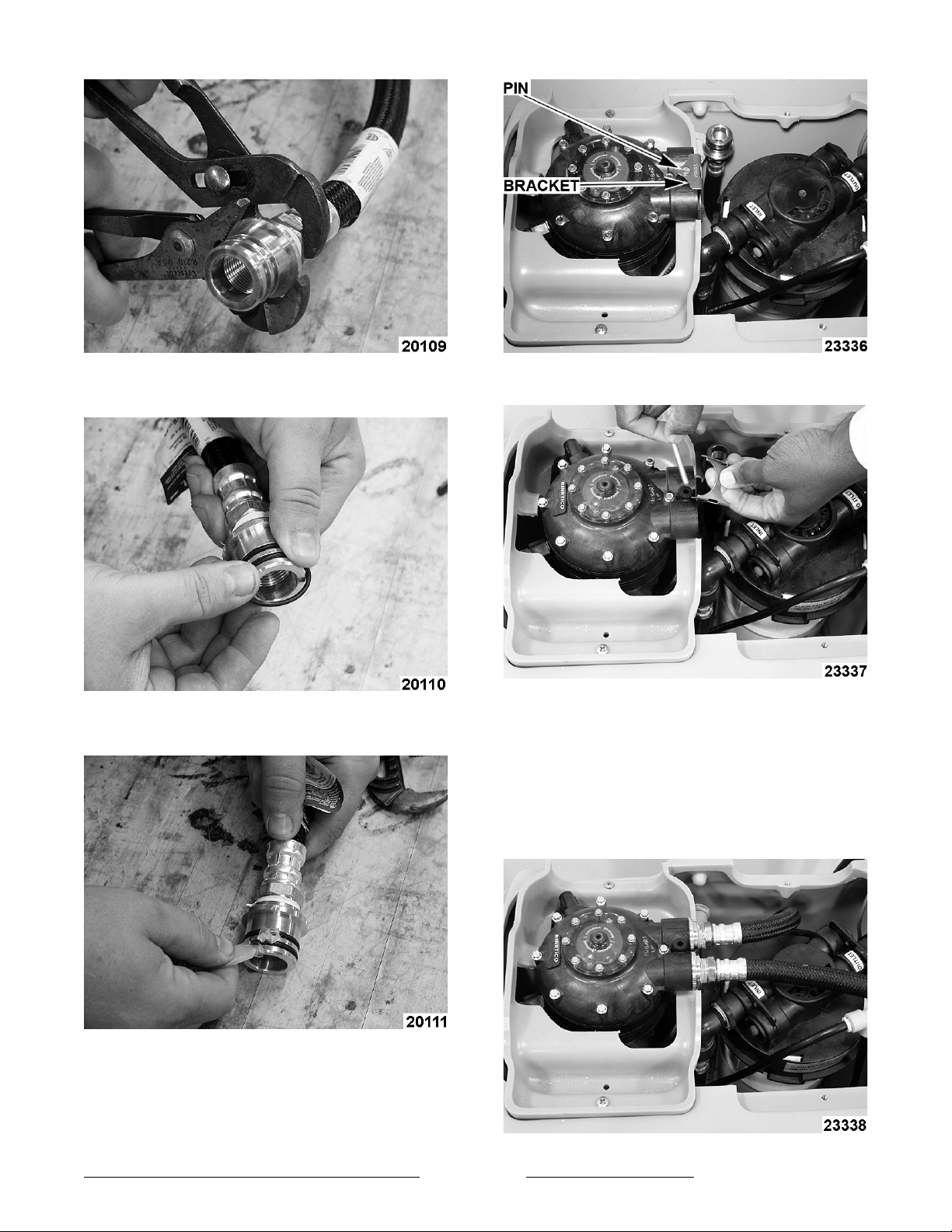
7. Thread the brass in/out adapters tightly onto the
threaded ends of the connector hoses.
8. Install one O-Ring into each groove of the brass
adapter.
10. Remove the pin and bracket from the softener
in/out port area.
9. Apply a small amount of seal lube evenly onto
each O-ring.
11. Install the brass adapters into the in/out ports
and secure by reinstalling the bracket and pin.
NOTE: The inlet connection from the building supply
is connected to the inlet of the carbon block filter
head. The outlet from the carbon block filter head is
connected to the inlet of the softener head. The
outlet from the softener head is connected to the
device.
F25407 (February 2011)Page 3 of 16
NOTE: The female end of the connector hoses is
designed to thread onto 3/4" pipe thread. Perform
appropriate plumbing to provide connections from
the water supply to the inlet hose/port and from the
outlet port/hose.
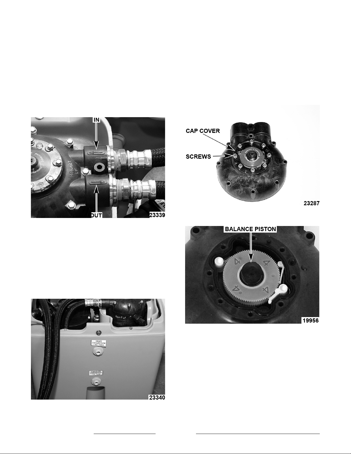
NOTE: The inlet port is identified with an arrow
pointing towards the softener controls. The softener
inlet port will receive the hose which is connected
from the outlet of the carbon block filter.
NOTE: The outlet port is identified with an arrow
pointing away from the softener controls. The outlet
port will receive the 60" hose that will connect to the
outlet plumbing. The supply connections should be
made before the pressure reducing valve.
15. To test the water supply, use the water analysis
test kit available through Pro Products Inc. The
recommended kit is #2404 Deluxe Field
Analysis Kit. To order the test kit contact Pro
Products at 800-285-9176 or visit
www.ProProducts.com.
16. Choose the meter disc and salt setting that best
fits the installation parameters.
NOTE: See DISC SELECTION at the end of
instructions.
17. To change disc, remove screws and cap cover
from level one.
12. Insert tubing provided into the drain port on the
back of the cabinet and run it to an appropriate
drain. Be sure to provide a “air gap” between
the end of the tubing and the top of the drain.
NOTE: Drain line length should not exceed 8 feet
vertical and 30 feet horizontal from the softener.
13. Insert tubing provided into the overflow port on
the back of the softener and run drain lower
than the cabinet connection to provide a gravity
drain in the event of a internal cabinet leak.
18. Remove balance piston.
14. Review the meter disc selection chart and the
water analysis provided. If no water analysis is
provided test the water supply.
F25407 (February 2011) Page 4 of 16
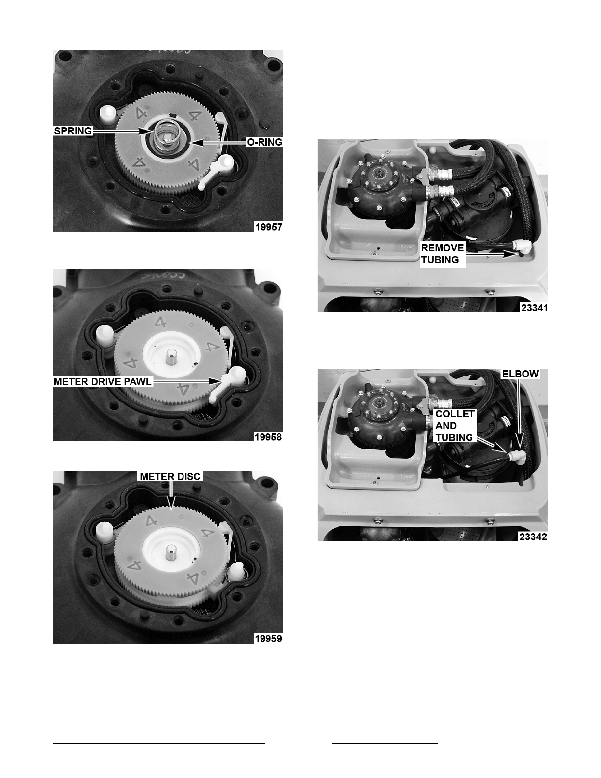
19. Remove balance piston o-ring and balance
piston spring.
20. Remove meter drive pawl.
NOTE: Be certain to start cap screws by hand
rotating backwards until screw drops into thread then
tighten. An alternating, crossing pattern should be
used while tightening cap screws to ensure correct
cap fit.
23. Remove brine valve assembly from cabinet to
set float cup.
24. To remove brine valve assembly, remove tubing
from softener cabinet.
21. Remove meter disc.
25. Disconnect tubing from brine valve elbow by
holding the collet and pulling tubing straight
away.
22. Install correct meter disc and reassemble in
reverse order.
NOTE: Make certain all components are correctly
installed.
F25407 (February 2011)Page 5 of 16

26. Remove brine valve from the softener cabinet.
27. The Float Cup is set by adjusting its height
above the bottom of the brine valve assembly.
By removing the brine valve assembly and
resting it on a flat surface, the height of the
Float Cup can be measured with a ruler.
The height is measured from the base of the brine
valve assembly to the top of the float cup.
Salt Alarm Installation
28. To install salt alarm system remove paper lining
from back of salt alarm connector box.
29. Remove plastic lining from Velcro
®
backing
located on back of salt alarm controller.
30. Remove four screws securing back cover to salt
alarm controller.
F25407 (February 2011) Page 6 of 16
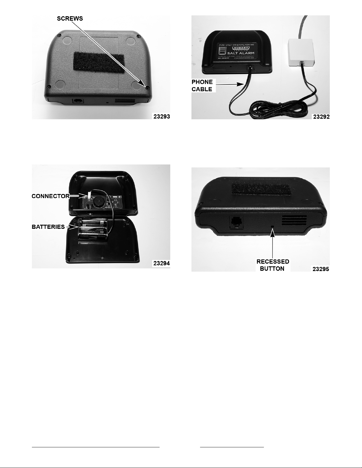
31. Install three (3) AA batteries into salt alarm
controller.
NOTE: When installing batteries - be certain to
inspect connector to ensure it is secure.
32. Re-install back cover to salt alarm controller.
33. Using the adhesive backing on both devices place alarm controller and salt alarm connector
box in a position that will allow salt alarm
controller to be seen and heard when it is
activated.
35. Check for proper operation by pressing the
recessed red button on bottom of salt alarm
controller. If controller is operating properly the indicator light will flash and an audible tone
will be heard.
34. Insert phone cable into salt alarm connector box
and salt alarm controller.
NOTE: Salt alarm controller can be mounted up to
100 feet from salt alarm connector box using
standard phone cable from local retailers (7 foot
cable is provide with kit).
F25407 (February 2011)Page 7 of 16

Brine Valve Settings
Unit Brine Setting WS-80 Float Cup Height
WS-55 1.4 lb. Setting 6.5"
36. After the adjustments have been made to the float cup, reinstall brine valve into the cabinet.
NOTE: Do not drop the brine valve into the drum. Dropping may lower the float cup, resulting in an improper
setting.
37. Add a clean grade of salt at this time. Higher grades of Pelletized Salt for impurities and solubility should be
used. NOTE: Do not use rock salt or solar salt.
38. Open the inlet valve slowly allowing the system to pressurize.
39. Water and air will be expelled from the drain until the system is completely pressurized.
40. A manual regeneration should be started to purge air and color from the softening system. This is done by
pushing down on the actuator with a Phillips screwdriver and rotating clockwise slowly until pressure is felt.
41. Continue slowly until internal water flow is heard at the softener valve. The softener will automatically run
through a regeneration. This process should be repeated in 12 to 15 minutes to flush the other resin tank.
42. Check for plumbing leaks.
43. Check unit for proper operation.
F25407 (February 2011)
Page 8 of 16

DISC SELECTION
The amount of hardness removed (in compensated gpg) will be based on the amount of brine and the meter disc
selected.
NOTE: Determining the correct brine valve setting for a particular application is a three step process:
1. Determine the compensated hardness. This requires a hardness test and an iron test on raw water at the
application site. Compensated hardness is calculated by multiplying the ferrous iron (in ppm) by 3 and adding
it to the grains of hardness.
2. To test the water supply, use the water analysis test kit available through Pro Products Inc. The
recommended kit is #2401 Field Analysis Kit. To order the test kit contact Pro Products at 800-285-9176 or
visit www.ProProducts.com.
WS-55
SettingCapacity EfficiencyDosingMeter Disc12345678
1.4 lbs. 4,818 grains 3,442 gr./lb. 3.5 lbs./ft
Gallons/Regeneration:
Flow during regeneration (@ 15 psig):
3
591 296 166 148 118 99 84 74
*Compensated hardness in gpg = Hardness + (3 x Fe in mg/l)
Disc Selection
(Compensated Hardness*)
6 13252730353740
55555555
F25407 (February 2011)Page 9 of 16

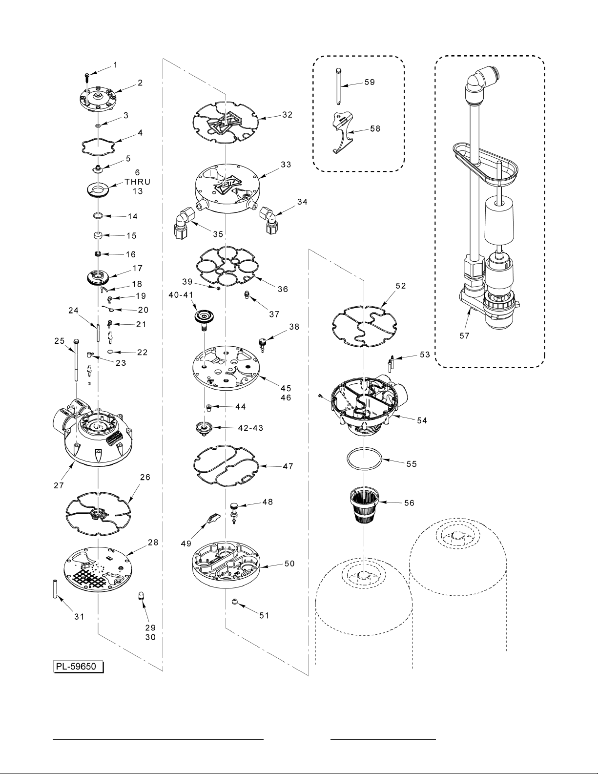
REPLACEMENT PARTS
Item
Number
1 00-913091-130 Cord Phone 7ft. 1
2 00-913091-129 Sensor Salt Alarm 1
3 00-913091-128 Salt Alarm Assy. 1
Part Number Description Qty.
F25407 (February 2011) Page 10 of 16
F25407 (February 2011)Page 11 of 16

Item
Number
1 00-913091-00067 Cap Screw 8
2 00-913091-00080 Cap 1
3 00-913091-00069 O-Ring (Actuator) 1
4 00-913091-00071 Seal – Cap 1
5 00-913091-00070 Actuator 1
6 00-913091-00072 Meter Disc 1 1
7 00-913091-00073 Meter Disc 2 1
8 00-913091-00074 Meter Disc 3 1
9 00-913091-00075 Meter Disc 4 1
10 00-913091-00076 Meter Disc 5 1
11 00-913091-00077 Meter Disc 6 1
12 00-913091-00078 Meter Disc 7 1
13 00-913091-00079 Meter Disc 8 1
14 00-913091-00009 O-Ring (Balance Piston) 1
15 00-913091-00008 Piston – Balance 1
16 00-913091-00010 Spring (Balance Piston) 1
17 00-913091-00011 Control Disc 1
18 00-913091-00012 Pawl (No Back) 1
19 00-913091-00013 Pawl – Meter Drive 1
20 00-913091-00014 Spring (Meter Drive Pawl) 1
21 00-913091-00015 Pawl – Regen Start 1
22 00-913091-00061 Filter 1
23 00-913091-00016 Pawl – Regen Drive 1
24 00-913091-00083 Pin – Support 1
25 00-913091-00085 Screw (Level 1) 8
26 00-913091-00017 Seal – Red (Level 1) 1
27 00-913091-00135 Level 1 Assy. 1
28 00-913091-00020 Level 2 1
29 00-913091-00021 Brine Flow Control (0.3 GPM) 1
30 00-913091-00022 Brine Flow Control (0.4 GPM) 1
31 00-913091-00100 Tube – Vent 1
32 00-913091-00023 Seal – Red (Level 2) 1
33 00-913091-00024 Level 3 1
34 00-913091-00087 Elbow – Brine 1
35 00-913091-00086 Elbow – Drain 1
36 00-913091-00025 Seal – Red (Level 3) 1
37 00-913091-00026 Venturi Throat (Dark Blue) 1
38 00-913091-00028 Control Valve (With Quad Ring) 1
39 00-913091-00097 Regeneration Flow Control 1
40 00-913091-00089 Main Piston (Incls. Item 41) 4
41 00-913091-00090 Quad Ring (Main Piston) 4
42 00-913091-00092 Valve Seat – Main (Incls. Item 43) 4
43 00-913091-00093 Seal – Main Valve 4
44 00-913091-00030 Backwash Flow Control 1
45 00-913091-00091 Level 4 1
46 00-913091-00027 Level 4 Assy. 1
47 00-913091-00031 Seal – Red (Level 4) 1
48 00-913091-00033 Drain Valve (With Quad Ring) 1
Part Number Description Qty.
F25407 (February 2011)
Page 12 of 16

Item
Number
49 00-913091-00035 Interlock 1
50 00-913091-00032 Level 5 1
51 00-913091-00034 Seal – Drain Valve 1
52 00-913091-00039 Seal – Main Base (Level 6) 1
53 00-913091-00040 Check Stems 1
54 00-913091-00037 Level 6 1
55 00-913091-00101 Ring – Main Base 1
56 00-913091-00041 Upper Distributor 1
57 00-913091-00133 Brine Valve Assy. 1
58 00-913091-00019 Bracket - Adapter 1
59 00-913091-00018 Pin – Cotterless Clevis 1
- - - 00-913091-00134 Complete Head Assy. 1
- - - 00-913091-00098 Drain Tube AR
- - - 00-913091-00099 Brine Tube AR
- - - 00-913091-00105 Back Cover (WS-80) 1
- - - 00-913091-00106 Front Lid (WS-80) 1
- - - 00-913091-00108 O-Ring In/Out 4
- - - 00-913091-00109 Caster Wheel (8mm) 4
- - - 00-913091-00044 Hose - In/Out 2
Part Number Description Qty.
Page 13 of 16
F25407 (February 2011)

- NOTES -
F25407 (February 2011) Page 14 of 16

- NOTES -
F25407 (February 2011)Page 15 of 16

- NOTES -
F25407 (February 2011) Printed in U.S.A.
 Loading...