

Page 1

I
N
S
T
R
U
C
T
I
O
N
S
WR SERIES
ENGINEERED WASTE SYSTEMS
MODEL L-R OPERATION R-L OPERATION
WR1000 ML-110372 ML-110373
701 S. RIDGE AVENUE
TROY, OHIO 45374-0001
937 332-3000
www.hobartcorp.com
FORM 33555 Rev. B (Feb. 2002)
Page 2
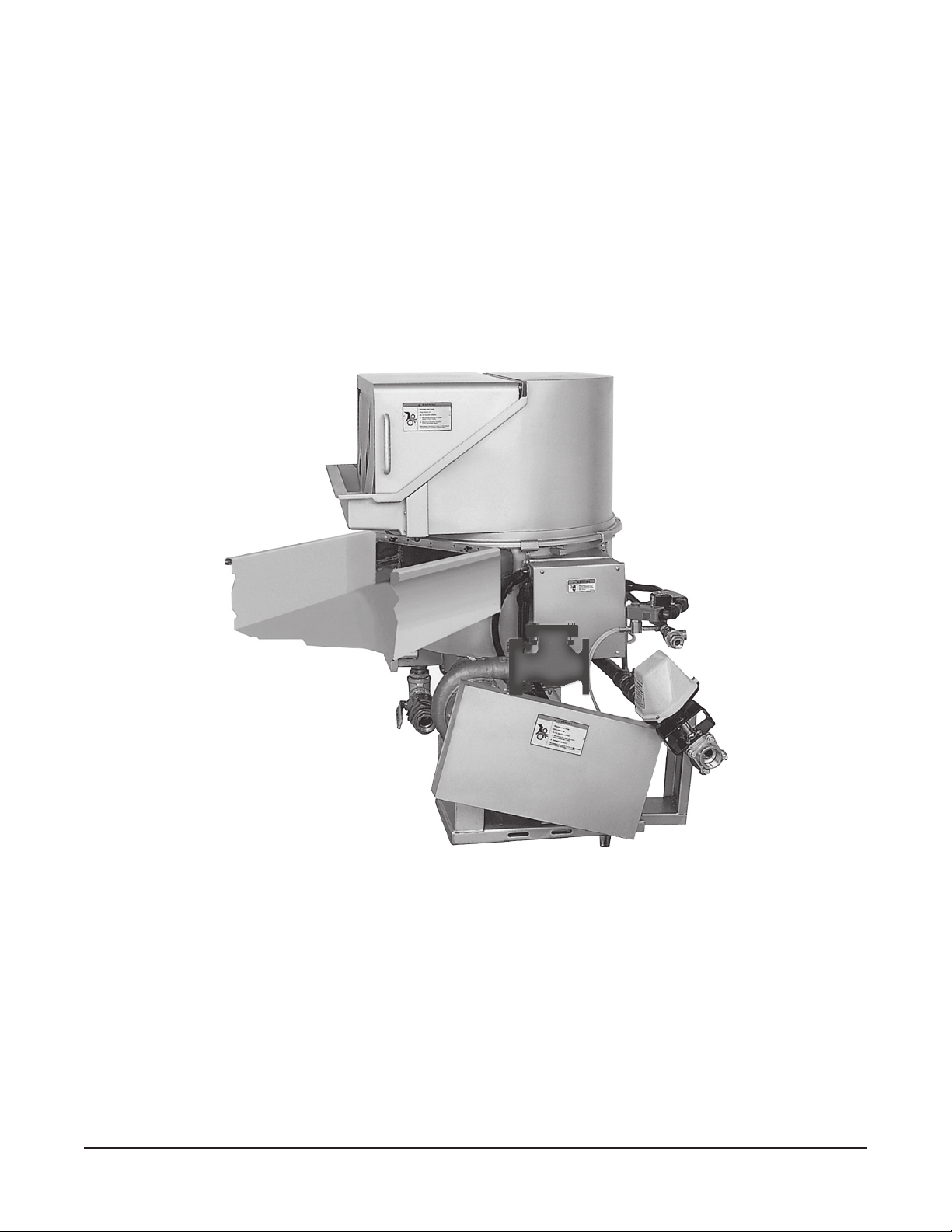
Model WR1000
© HOBART CORPORATION, 1996
–2–
Page 3

Installation, Operation and Care of
WR SERIES
ENGINEERED WASTE SYSTEMS
SAVE THESE INSTRUCTIONS
GENERAL
The WR Series Engineered Waste System is comprised of one or more pulpers, a piping system and
a waterpress. The pulper uses a 7.5 horsepower motor, stainless steel components and carbide steel
cutting edges to shred grindable waste to a pumpable slurry. The slurry is pumped through the piping
system to the waterpress where a stainless steel screw squeezes out the moisture, compacts the waste
and lifts the semi-dry pulp to the discharge chute — reducing the original volume significantly. Process
water is pumped back to the pulper(s) where it recycles.
Modular design of the WR Series Engineered Waste System allows one or more pulpers to be located
remote from the waterpress. Required piping to connect the waterpress to the pulpers is to be supplied
by others and installed per Hobart piping drawing. Pumps, motors and controls are supplied per the
order and the sales installation drawings. Because each installation is unique to the site, follow the
sales installation drawings carefully during the installation process.
Additionally, the pulper may be installed undercounter with a water-tight trough connection; a silversaver sink with lift-out basket (by others) can be installed with the trough.
INSTALLATION
Prior to installation, test the electrical service to make sure that it agrees with the specifications. Plan
the location of plumbing and electrical components for operator safety, ease of operation and cleaning.
UNPACKING
Immediately after unpacking, check for possible shipping damage. If the units are found to be
damaged, save the packaging material and contact the carrier within 15 days of delivery. Identify and
group the components, matching with the proper units. Do not discard or misplace components. Do
not mismatch components with the wrong units.
LOCATION
Both the pulper and the waterpress should be located near a floor drain; floor should be pitched a
minimum of
operation, cleaning and service.
LEVELING
Vibration Isolation Pads (standard, Fig. 1) must be installed under each
Leg of the pulper and slurry pump before making connections. Level by
threading the Adjustable Feet up or down as necessary. After leveling,
tighten the Setscrew on the Foot Flange.
1
/4" per foot to the floor drain. A suitable amount of space should be provided for machine
LEG
ADJUSTABLE
FOOT
RUBBER WAFFLE
VIBRATION
ISOLATION PADS
Fig. 1
SETSCREW
FOOT FLANGE
BOLT
SOLE PLATE
–3–
Page 4
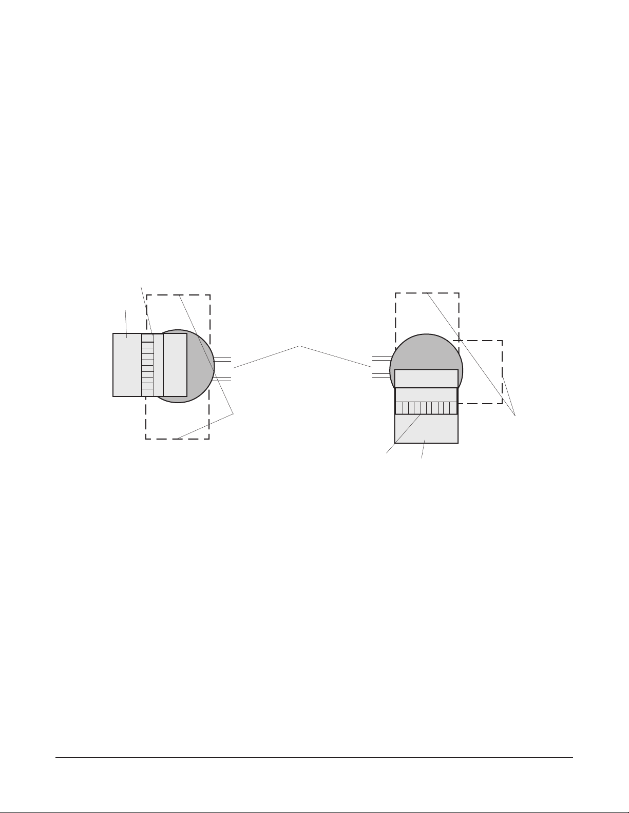
FEED TRAY (Optional Lengths) AND HOOD (Standard)
The feed tray extending from the pulper is available in three lengths: Short (20"), medium (36"
standard) or long (42"). The hood is positioned over the pulper and has an interlock. When the hood
is lowered, material can move from the feed tray to the pulper through the curtains. The feed tray and
hood can be installed in one of three 90° positions (Fig. 2).
TRAY FLUSH (Optional with Feed Tray and Hood)
When equipped, the tray flush is attached to the end of the feed tray. The tray flush is plumbed to the
return water line, either at the factory or in the field by qualified installer or technician.
PULPER (Fig. 2)
FEED TRAY
Left-to-Right Operation
HOOD
PIPING SYSTEM
TO AND FROM
REMOTE LOCATED
WATERPRESS.
ALTERNATE
FEED TRAY
POSITIONS
Fig. 2
Right-to-Left Operation
HOOD
FEED TRAY
ALTERNATE
FEED TRAY
POSITIONS
UNDERCOUNTER (Optional)
Undercounter models use a feed table (by others) with transition ring (by Hobart) welded underneath
the feed table per instructions (Fig. 3) instead of the Feed Tray and Hood. Install the reed switch packed
at the junction box to the location indicated (Fig. 3). Undercounter models are provided with either a
cover plate or a single opening feed hood, which must be placed over the pulper opening of the feed
table. On undercounter models, either the cover plate or the single opening feed hood is the pulper
cover.
If equipped with a cover plate, rotate the cover plate so the magnet aligns with reed switch and the cover
plate will drop flush into the feed table opening.
If equipped with the single opening feed hood, the magnet is factory installed in the location opposite
the feed opening. This location is appropriate only if the feed opening is oriented 180° from the slurry
pump assembly. If the feed opening is positioned at either 90° orientation, relocate the magnet
assembly so it aligns with the reed switch. The single-opening feed hood drops into the table opening
so it is level and the magnet operates the reed switch.
The magnet and reed switch will always be located next to the slurry pump assembly.
–4–
Page 5

Fig. 3
PIPING SYSTEM
Follow the piping details, piping schematic and installation drawings when installing the piping system.
Note the plumbing installation tips, page 6.
RETURN PUMP
The return pump is mounted on the waterpress to pump the recycled water back to the pulper for reuse.
–5–
Page 6

PLUMBING CONNECTIONS
WARNING: PLUMBING CONNECTIONS MUST COMPLY WITH APPLICABLE SANITARY, SAFETY
AND PLUMBING CODES.
Water Connections
Incoming water supplies to the pulper and waterpress should be connected to the
3
/4" NPT connector
provided. Incoming water pressure must be between 25 psig and 45 psig flowing.
Drain Connections
The drains for both the pulper and the waterpress must be plumbed to a suitable drain per local code.
Refer to installation drawings.
Slurry Line, Return Line, etc.
Connect the slurry line and the return line and other piping connections per the installation and piping
drawings. Pressure test piping system for leaks at 150 psig.
PLUMBING INSTALLATION TIPS
Use recommended pipe sizes. Do not increase or decrease pipe sizes from those recommended.
Use copper piping for the slurry line and return line. Keep track of the direction of flow while plumbing
the slurry and return lines (mark with a marker pen as you go along). Use only long radius T - Y type
cleanouts or lateral type fittings and 45° elbows (Fig. 4). Install cleanouts at all turns and every 50 feet
of straight pipe runs. Make sure cleanouts are accessible. Install cleanouts so the water does not flow
into the cleanout to avoid probable jamming and clogging (Fig. 4).
Do not use 90° elbows or right angle turns — jams could occur and stop the flow.
Plan piping layouts without drastic elevation changes that could cause airlocks and stop the flow.
Terminate slurry and return lines with union or flanged type fittings.
Install a manual shutoff valve on incoming fresh water lines to allow servicing.
Install all valves and other components as shown on the installation drawings.
Piping must run uphill to trough connection if feed table is equipped with a trough.
RIGHT ANGLE TURN
USING 45 ELBOW & 45 Y FITTINGS
o
Cleanout
Plug
o
45 Elbow
Flow
o
o
45 Y Branch
Flow
Cleanout
Plug
STRAIGHT PIPE
USING LONG RADIUS T-Y TYPE FITTING
RIGHT ANGLE TURN
Cleanout
Plug
Fig. 4
Long Radius
T-Y Fitting
Flow
Cleanout
Plug
WRONG FLOW DIRECTION
Long Radius
T-Y Fitting
PL-52215
–6–
Page 7

ELECTRICAL CONNECTIONS
WARNING: ELECTRICAL AND GROUNDING CONNECTIONS MUST COMPLY WITH APPLICABLE
PORTIONS OF THE NATIONAL ELECTRICAL CODE AND/OR OTHER LOCAL ELECTRICAL CODES.
WARNING: DISCONNECT ELECTRICAL POWER SUPPLY AND PLACE A TAG AT THE DISCONNECT
SWITCH INDICATING THAT YOU ARE WORKING ON THE CIRCUIT.
Refer to the electrical diagram located on the inside of the control box and the installation drawings.
MAIN POWER CONTROL PANELS
Each main power control panel (NEMA 12) is typically located nearby but remote from the respective
pulper or waterpress it serves. Each main power control panel is identified by the serial number of the
respective pulper or waterpress it is designed to serve. Match the serial numbers to make sure the
correct main power control panel is connected to the proper pulper or waterpress. Separate incoming
power must be supplied to each main power control panel. To facilitate field wiring, terminal blocks
inside each main power control panel are labeled for the interconnecting wiring of the corresponding
serial numbered pulper or waterpress as well as the terminal blocks in the enclosures located on the
respective pulper or waterpress. Conduit and wiring (by others) should be installed according to the
electrical diagram and the installation drawings.
REMOTE START – STOP STATIONS
One or more remote junction boxes with push-button Start and Stop switches may be provided as
ordered. These should be installed in suitable and convenient locations per local codes, the electrical
diagram and the installation drawings. They should be securely mounted and located at a convenient
location for ease of operation, but not where they can be damaged or bumped.
INTERCONNECTING WIRING INSTALLATION TIPS
All pulper control panels must be interconnected with the waterpress control panel. Also, connecting
wires (not supplied) must be connected from individual main power control panels to system
components, such as start-stop stations, interlock switches, 3-phase drive motors, motorized valves,
solenoid valves, slurry and return pump(s), etc. — all according to the electrical diagram, the
installation drawings and the code numbers on the terminal blocks.
Motor Rotation
The pulper motor, waterpress motor, slurry pump motor and return pump motor must be checked for
correct rotation after the machine has filled. Arrows are provided to indicate the correct directions of
motor rotation. Motor shafts are visible to make this verification.
To check motor rotation, turn power on. Start and stop the machine. Observe direction of motors.
If incorrect direction of rotation is observed, DISCONNECT ELECTRICAL POWER SUPPLY.
Interchange two power supply leads to any motors that have incorrect rotation. Close electrical access
panels. Reconnect electrical power. Turn machine on momentarily to verify correct motor rotation.
– 7 –
Page 8

OPERATION
WARNING: THE PULPER COVER AND THE DISCHARGE CHUTE ARE EQUIPPED WITH
INTERLOCK DEVICES. THE PULPER COVER MUST BE IN PLACE AND THE DISCHARGE CHUTE
MUST BE LOWERED BEFORE THE MACHINE IS USED.
CONTROLS (Fig. 5)
Main Control Push-Button Station Optional Push-Button Station
Panel Standard With Manual-Auto Switch
MAN–AUTO
PUMP DOWN
START
STOP
ON
PUMP DOWN
OFF
START
STOP
Fig. 5
The operator controls should be conveniently located near the pulper.
Power disconnect to the machine may be provided by the building electric system or by turning the
handle on the Main Control Panel OFF.
START — Turns ON the water supply and fills the tank. As soon as the tank is full,
the pulper motor, waterpress and slurry and return pumps come on, and
the motorized valve opens.
STOP — Turns OFF the water supply valve, pulper motor, waterpress motor and
slurry and return pumps. The motorized valve closes.
PUMP DOWN — Opens motorized valve at waterpress, closes motorized valve at pulper.
This diverts water in the system to the drain. Pulper will shut down after
preset time has expired.
MAN – AUTO (Optional) — MANUAL operation is normal operation. AUTO operation will allow the
machine to run for a preset amount of time before it automatically shuts
off the machine.
Using the Pulper
1. The pulper's feed hood curtains should be in place and the feed hood must be closed (when
equipped). Lower the discharge chute and replace the door on the waterpress.
2. The drain valves located at waterpress and pulper must be closed. The water supply valve must
be open. The Main Power switch must be ON.
3. Press the START button. The machine begins filling with water. When the machine has filled
to the proper level, the pulper, waterpress, slurry and return pump motors start automatically.
Allow an additional 2 minutes after the motors come on before feeding waste. During operation,
water may intermittently enter the tank through the fill port. After the motors have come on, the
system is controlled by the START and STOP buttons.
– 8 –
Page 9

Feeding Waste
Waste material should be fed into the pulper no faster than the machine can process it. DO NOT
OVERLOAD PULPER. A good gauge for correct feed rate is to feed waste as fast as possible, provided
the material continues to rotate in the pulping tank. If the rotation or vortex is stopped due to
overfeeding, wait a few minutes until rotation resumes. Production can be improved by mixing the
waste whenever possible. Corrugated boxes, for example, can be mixed with food service waste that
would come from a typical dining area. During normal operation, there should be a strong flow of water
returning to the pulper from the waterpress. This flow is a clue to the performance of the machine since
a sharp reduction in this flow indicates the pulper is overloaded. If this occurs, stop feeding for a few
minutes until return water resumes its normal flow.
Avoid slugging the machine with greasy swill or overloading the pulper with bread or pastry. Mix these
items with bulky waste such as corrugated boxes. The pulper will always perform better with clean,
cold water. It is good practice to drain the machine of dirty water after every meal cycle.
It is recommended that the discharge receptacle (garbage can) not be taller than the bottom of the
discharge chute. Empty receptacle whenever necessary.
Add corrugated boxes at regular intervals while processing.
Special Feeding Instructions
Some waste materials require special feeding techniques to utilize the equipment most efficiently.
Heavy printed matter, computer cards, bulletins, computer printouts, Styrofoam and catalogs should
be fed gradually to avoid overloading.
If waste material is delivered in large plastic bags, tear open and feed one bag at a time. Unopened
bags can fill with air and float, hampering machine operation.
DO NOT FEED glass or metal containers; if present in the plastic bags, sort them out. Glass and metal
containers are highly abrasive and accelerate machine wear. It is better to recycle glass or metal
containers using a can or bottle crusher to reduce the volume.
DO NOT FEED rags, mop heads, wooden crates, oyster or clam shells or heavy uncooked bones to
the pulper. The waste system cannot efficiently reduce the volume of these items.
Foaming
Waste materials with a glossy finished paper or a high glue content tend to create foam in the pulper
tank. If there is excessive foaming in the pulper, it can interfere with the pulping process. Special antifoaming chemicals and metering pumps to inject the chemicals at a uniform rate are available from
chemical supply companies.
– 9 –
Page 10

CLEANING
5
3
3
Cleaning requires only a few minutes daily, but must be done on a regular basis and proper facilities
must be available. NOTE: If daily cleaning schedules are not followed, the machine will become
unsightly and odors will develop. A hose with a good quality, lever-operated nozzle should be
available, preferrably with hot water, for clean-up of both the machine and the surrounding area.
Save several boxes of paper trash or corrugated cardboard boxes and send them through the pulper
at the end of the operating period.
If equipped with the automatic shutdown option, turn the selector switch to the auto mode. The system
will process the final load for 15 minutes before automatically shutting down.
If not equipped with automatic shutdown, allow at least ten minutes for the final load of paper or
cardboard trash to be processed. Press the STOP button and wait for the pulper disk to stop rotating.
WARNING: DISCONNECT ELECTRIC POWER SUPPLIES AT CONTROL BOXES. PLACE TAGS AT
THE DISCONNECT SWITCHES INDICATING THAT YOU ARE WORKING ON THE CIRCUITS. WAIT
FOR MACHINES TO COME TO A COMPLETE STOP BEFORE PERFORMING ANY CLEANING
PROCEDURES.
Pulper
Open the feed hood or pulper cover plate and remove materials that may be floating on the water —
use a strainer or skim tool.
If equipped with the feed hood and tray option, remove the curtains from the clips on the hood. Open
drain valve and drain the machine. Scoop any loose trash remaining in the pulper into a trash container.
Use a hose and wash the inside of the pulper tank (and feed hood and curtains, if equipped).
Open and remove the trash box (Fig. 6). Empty and clean the trash box. Clean inside the trash box
receptacle area. Replace the trash box.
Waterpress
Remove the waterpress access door. Use the hose at high pressure to wash down the interior of the
housing and screen. Lift the chute and remove any loose pulp remaining in the discharge chute and
at the top of the waterpress screw. Flush lightly with the hose. It is not necessary to dig out the plug
of pulp remaining at the top of the waterpress screw. After the machine has been cleaned, wash down
the floor, close the drain valve and dispose of any objects removed from the discharge chute. Replace
all removed parts.
HOOD
FEED TRAY
PULPER
TRASH BOX
234567890123456789012
234567890123456789012
234
Fig. 6
– 10 –
Page 11

MAINTENANCE
WARNING: DISCONNECT ELECTRIC POWER SUPPLIES AT CONTROL BOXES. PLACE TAGS AT
THE DISCONNECT SWITCHES INDICATING THAT YOU ARE WORKING ON THE CIRCUITS. WAIT
FOR MACHINES TO COME TO A COMPLETE STOP BEFORE PERFORMING ANY MAINTENANCE
PROCEDURES.
MOTORS
Motors should be kept free of dirt, and ventilation openings must not be restricted.
WATERPRESS DRIVE
The waterpress drive consists of a motor and speed reducer. The motor requires no lubrication
maintenance. The speed reducer is oil lubricated and the oil level should be checked every two or three
months. With the machine stopped, remove the oil level plug. If the oil level is not high enough to drain
out of the case, add a small quantity of Mobil SHC-634 or equivalent until it just starts to run out of the
hole.
TROUBLESHOOTING
motpmySesuaCelbissoPydemeRelbissoP
lliwrepluP
.1
.tratston
.2
.ffOsirepluprosserpretaw
.3
.4
.5
.6
.ffOsi
sserpretaW
.1
tonlliw
.trats
.retaw
.2
.ffOsisserpretawroreplup
.3
.4
.5
roretawoN
.1
tneiciffusni
.2
pu-ekam
.3
.4
.desolcsievlavffotuhS
.neposievlavniarD
.noitisopreporpnitonrevocrepluP
.retawpu-ekamtneiciffusniroretawoN
.noitisopreporpnitonrevocrepluP
.retawpu-ekamtneiciffusniroretawoN
.desolcsievlavylppusretawniaM
.OTUAnosihctiwsrotceleseht
.ylppusrewopgnidliubtadeppirtrekaerbtiucriC
.1
rehtietalenaplortnocniamnoeldnahrewoP
.2
.tratShsupdnanoitisop
.3
.noitisopreporpstinitonsietuhcsserpretaW
.4
.5
rodeppirtsahrekaerbtiucricrotomnoeldnaH
.6
.ylppusrewopgnidliubtadeppirtrekaerbtiucriC
.1
rehtietalenaplortnocniamnoeldnahrewoP
.2
.3
.noitisopreporpstinitonsietuhcsserpretaW
.4
.5
.1
.2
ro,dehsupneebevahyamhctiwsnwoDpmuP
.3
.4
.enihcamtratseR
.evlavniardesolC
.rekaerbtiucricteserroesufecalpeR
nOotlenaplortnocniamnoeldnahnruT
.noitisopreporpnirevocrepluptuP
.noitisopreporpstinietuhcsserpretawtuP
".retawpu-ekamtneiciffusniroretawoN"eeS
.noitisopnOotrekaerbtiucricnruT
.rekaerbtiucricteserroesufecalpeR
.noitisopnOotrekaerbtiucricnruT
.noitisopreporpnirevocrepluptuP
.noitisopreporpstinietuhcsserpretawtuP
".retawpu-ekamtneiciffusniroretawoN"eeS
.evlavylppusretawniamnepO
.enilylppusnisevlavffotuhsllanepO
– 11 –
Page 12

TROUBLESHOOTING (continued)
motpmySesuaCelbissoPydemeRelbissoP
sserpretaW
.1
.demmaj
.2
.3
niardtonlliW
.1
sniardro
.ylwolsyrev
.2
.3
.llufxobhsarT
.deggolcesohniarD
.detcurtsboteltuoetuhcegrahcsiD
.sserpretawnigulpdenedraH
plupdnallufreniatnochsarT
.etuhcegrahcsidnipugnikcab
.lairetamdeplupnufollufrepluP
.1
.pluplaudiser
.2
.lairetametsawdenedrah
.3
.etuhcegrahcsid
.1
.knatreplupedisnimorftuo
.2
.knatrepluptuonaelc
.3
.golcetanimileoterusserpretaw
evomeR.lenaplortnocniamtaenihcamffonruT
evomeR.lenaplortnocniamtaenihcamffonruT
morfplupesoolevomerdnareniatnochsartytpmE
tonoD.lenaplortnocniamtaenihcamffonruT
naelcdnasevolgevitcetorpraeW.xobhsartevomer
tonlliwtifI.dessecorpsipluplitnureplupnuR
dnalenaplortnocniamtaenihcamffonrut,ssecorp
esudna)rebmulpybdellatsni(gulptuonaelcevomeR
evissecxE
repluP
.demmaj
.1hcus,slairetamniatrecfognipluP
nignimaof
.sserpretaw
.maoffo
.1
.2
.dedaolrevorepluP
.lairetamyvaehrolatem
dnadraobdrac,repapyssolgsa
parcshtiwdemmajcsidgnipluP
.1.tnegagnimaofedaesU.a
.retawhserfhtiwlliferdnaenihcamniarD.b
seititnauqegralsecudorp,seotatop
.1
.tratserdnaknat
.2
.lairetamyvaehrolatem
.etsawgnideeftonnehwfforeplupnruT.c
replupnaelC.lenaplortnocniamtaffoenihcamnruT
evomeR.lenaplortnocniamtaffoenihcamnruT
SERVICE
Contact your local Hobart-authorized Service Office for any repairs or adjustments needed on this
equipment.
FORM 33555 Rev. B (Feb. 2002) PRINTED IN U.S.A.
– 12 –
 Loading...