

Page 1

HQC135 & HQC200 QUICKCHILLERS
MODEL
HQC135 ML-124069
HQC200 ML-124070
701 S. RIDGE AVENUE
TROY, OHIO 45374-0001
937 332-3000
www.hobartcorp.com
FORM 34643 Rev. A (Sept. 2001)
Page 2
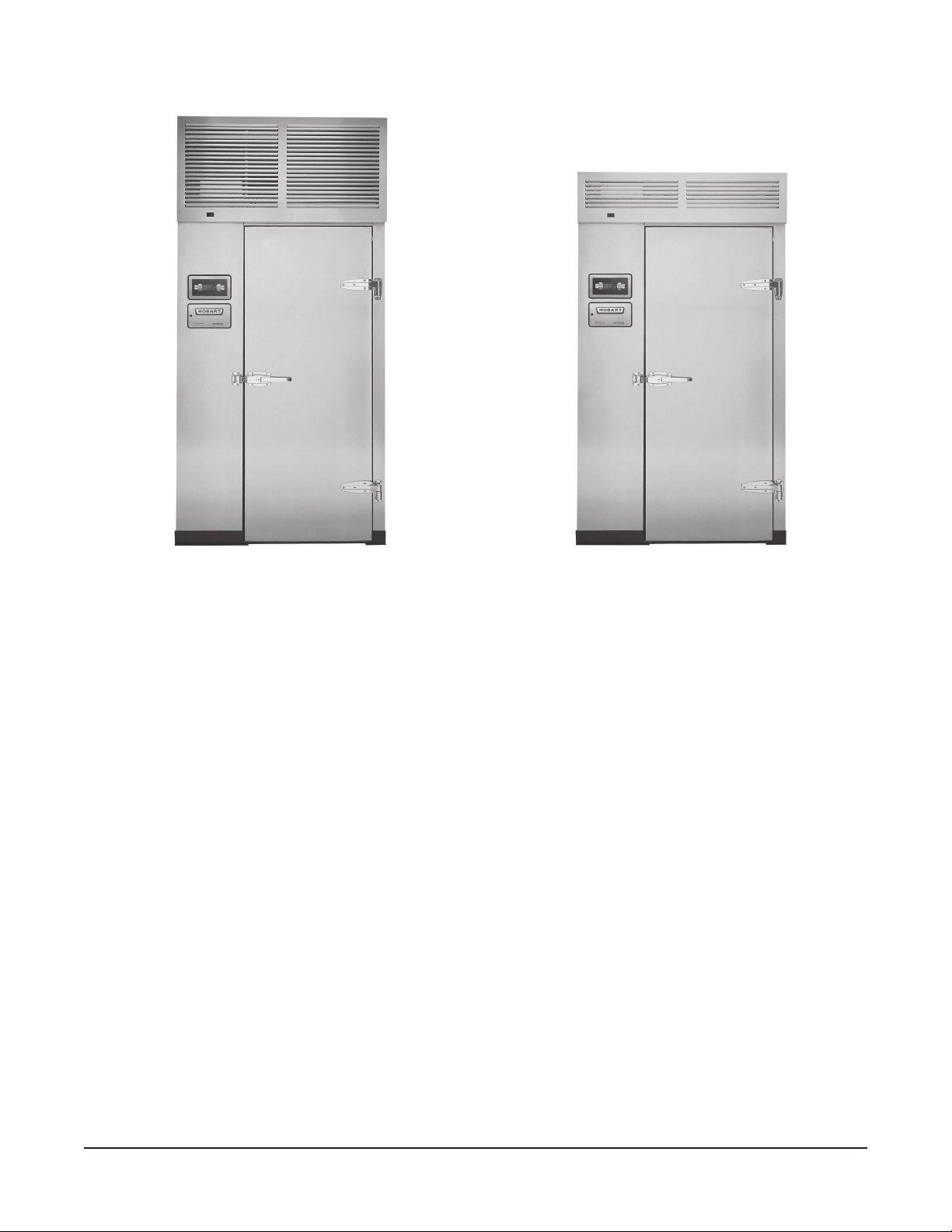
Model HQC135 QuickChiller Model HQC200 QuickChiller
TABLE OF CONTENTS
GENERAL . . . . . . . . . . . . . . . . . . . . . . . . . . . . . . . . . . . . . . . . . . . . . . . . . . . . . . . . . . . . . 4
INSTALLATION. . . . . . . . . . . . . . . . . . . . . . . . . . . . . . . . . . . . . . . . . . . . . . . . . . . . . . . . . 4
UNCRATING . . . . . . . . . . . . . . . . . . . . . . . . . . . . . . . . . . . . . . . . . . . . . . . . . . . . . . . . 4
LOCATION. . . . . . . . . . . . . . . . . . . . . . . . . . . . . . . . . . . . . . . . . . . . . . . . . . . . . . . . . . 5
INSTALLATION WITH OPTIONAL INSULATED FLOOR PANEL . . . . . . . . . . . . . . 5
INSTALLATION WITHOUT OPTIONAL INSULATED FLOOR PANEL . . . . . . . . . . 5
INSTALLATION WITH OPTIONAL STAINLESS STEEL SHEET METAL FLOOR . 5
PANEL ASSEMBLY . . . . . . . . . . . . . . . . . . . . . . . . . . . . . . . . . . . . . . . . . . . . . . . . . . 6
ASSEMBLY . . . . . . . . . . . . . . . . . . . . . . . . . . . . . . . . . . . . . . . . . . . . . . . . . . . . . . . . . 7
INTERNAL ELECTRICAL CONNECTIONS . . . . . . . . . . . . . . . . . . . . . . . . . . . . 8
Product Probe Assembly . . . . . . . . . . . . . . . . . . . . . . . . . . . . . . . . . . . . . . 10
Temperature Control Sensors . . . . . . . . . . . . . . . . . . . . . . . . . . . . . . . . . . 11
Fans and Defrost Heaters . . . . . . . . . . . . . . . . . . . . . . . . . . . . . . . . . . . . . 12
REFRIGERATION CONNECTIONS . . . . . . . . . . . . . . . . . . . . . . . . . . . . . . . . . 12
DRAIN LINE INSTALLATION . . . . . . . . . . . . . . . . . . . . . . . . . . . . . . . . . . . . . . 12
INTERIOR FINISH DETAILS. . . . . . . . . . . . . . . . . . . . . . . . . . . . . . . . . . . . . . . 12
INSTALLATION OF REMOTE ALARM . . . . . . . . . . . . . . . . . . . . . . . . . . . . . . . . . . 12
ELECTRICAL CONNECTIONS . . . . . . . . . . . . . . . . . . . . . . . . . . . . . . . . . . . . . . . . 13
HOBART CORPORATION, 2001
– 2 –
Page 3

INSTALLATION — REMOTE CONDENSING UNITS . . . . . . . . . . . . . . . . . . . . . . . 14
GENERAL. . . . . . . . . . . . . . . . . . . . . . . . . . . . . . . . . . . . . . . . . . . . . . . . . . . . . . 14
ELECTRICAL CONNECTIONS . . . . . . . . . . . . . . . . . . . . . . . . . . . . . . . . . . . . . 14
CONDENSER RECOMMENDATIONS . . . . . . . . . . . . . . . . . . . . . . . . . . . . . . . 14
PIPE SIZING GUIDELINES. . . . . . . . . . . . . . . . . . . . . . . . . . . . . . . . . . . . . . . . 15
OUTDOOR CONDENSING UNITS . . . . . . . . . . . . . . . . . . . . . . . . . . . . . . . . . . 15
VALVE AND PRESSURE SETTINGS . . . . . . . . . . . . . . . . . . . . . . . . . . . . . . . 15
WATER COOLED CONDENSING UNITS . . . . . . . . . . . . . . . . . . . . . . . . . . . . 16
OPERATION . . . . . . . . . . . . . . . . . . . . . . . . . . . . . . . . . . . . . . . . . . . . . . . . . . . . . . . . . . 18
CONTROLS . . . . . . . . . . . . . . . . . . . . . . . . . . . . . . . . . . . . . . . . . . . . . . . . . . . . . . . . 18
START-UP . . . . . . . . . . . . . . . . . . . . . . . . . . . . . . . . . . . . . . . . . . . . . . . . . . . . . . . . . 18
OVER TEMPERATURE . . . . . . . . . . . . . . . . . . . . . . . . . . . . . . . . . . . . . . . . . . . . . . 18
PROBES . . . . . . . . . . . . . . . . . . . . . . . . . . . . . . . . . . . . . . . . . . . . . . . . . . . . . . . . . . 18
DOOR SWITCH . . . . . . . . . . . . . . . . . . . . . . . . . . . . . . . . . . . . . . . . . . . . . . . . . . . . . 18
FAN DOOR SWITCH . . . . . . . . . . . . . . . . . . . . . . . . . . . . . . . . . . . . . . . . . . . . . . . . 18
PRINTER SUPPLIES . . . . . . . . . . . . . . . . . . . . . . . . . . . . . . . . . . . . . . . . . . . . . . . . 19
LOADING ROLL STOCK ONTO THE PRINTERS . . . . . . . . . . . . . . . . . . . . . . . . . 19
Plain Thermal Paper . . . . . . . . . . . . . . . . . . . . . . . . . . . . . . . . . . . . . . . . . . . . . 19
Adhesive-Backed Label Stock for Optional Label Printer . . . . . . . . . . . . . . . . 19
WHEN POWER IS RESTORED AFTER A POWER INTERRUPTION . . . . . . . . . 19
MAIN MENU — Chill: BY TEMP . . . . . . . . . . . . . . . . . . . . . . . . . . . . . . . . . . . . . . . . 20
MAIN MENU — Chill: BY TIME . . . . . . . . . . . . . . . . . . . . . . . . . . . . . . . . . . . . . . . . 22
MAIN MENU — Chill: BY PROD . . . . . . . . . . . . . . . . . . . . . . . . . . . . . . . . . . . . . . . 24
PRODUCT LIST . . . . . . . . . . . . . . . . . . . . . . . . . . . . . . . . . . . . . . . . . . . . . . . . . . . . 26
HOLD PROD . . . . . . . . . . . . . . . . . . . . . . . . . . . . . . . . . . . . . . . . . . . . . . . . . . . . . . . 27
DEFROST . . . . . . . . . . . . . . . . . . . . . . . . . . . . . . . . . . . . . . . . . . . . . . . . . . . . . . . . . 27
PRINT . . . . . . . . . . . . . . . . . . . . . . . . . . . . . . . . . . . . . . . . . . . . . . . . . . . . . . . . . . . . 27
SETUP — PRODUCTS . . . . . . . . . . . . . . . . . . . . . . . . . . . . . . . . . . . . . . . . . . . . . . . 28
SETUP — USERS . . . . . . . . . . . . . . . . . . . . . . . . . . . . . . . . . . . . . . . . . . . . . . . . . . . 29
SYS PAR . . . . . . . . . . . . . . . . . . . . . . . . . . . . . . . . . . . . . . . . . . . . . . . . . . . . . . . . . . 30
CLOCK . . . . . . . . . . . . . . . . . . . . . . . . . . . . . . . . . . . . . . . . . . . . . . . . . . . . . . . . 31
PROBES . . . . . . . . . . . . . . . . . . . . . . . . . . . . . . . . . . . . . . . . . . . . . . . . . . . . . . . 32
TEMPS IN °F . . . . . . . . . . . . . . . . . . . . . . . . . . . . . . . . . . . . . . . . . . . . . . . . . . . 32
LOGGING . . . . . . . . . . . . . . . . . . . . . . . . . . . . . . . . . . . . . . . . . . . . . . . . . . . . . . 32
REMOTE ALARM. . . . . . . . . . . . . . . . . . . . . . . . . . . . . . . . . . . . . . . . . . . . . . . . 33
ALARMS . . . . . . . . . . . . . . . . . . . . . . . . . . . . . . . . . . . . . . . . . . . . . . . . . . . . . . . 34
MODE Parameters — CHILL . . . . . . . . . . . . . . . . . . . . . . . . . . . . . . . . . . . . . . 35
MODE Parameters — SOFT CHILL . . . . . . . . . . . . . . . . . . . . . . . . . . . . . . . . . 36
BUZZER . . . . . . . . . . . . . . . . . . . . . . . . . . . . . . . . . . . . . . . . . . . . . . . . . . . . . . . 37
FAC PRESETS . . . . . . . . . . . . . . . . . . . . . . . . . . . . . . . . . . . . . . . . . . . . . . . . . 37
GLOSSARY . . . . . . . . . . . . . . . . . . . . . . . . . . . . . . . . . . . . . . . . . . . . . . . . . . . . . . . . 38
COMMUNICATION WITH SmartChill™ . . . . . . . . . . . . . . . . . . . . . . . . . . . . . . . . . . 39
MAINTENANCE . . . . . . . . . . . . . . . . . . . . . . . . . . . . . . . . . . . . . . . . . . . . . . . . . . . . . . . 40
CLEANING. . . . . . . . . . . . . . . . . . . . . . . . . . . . . . . . . . . . . . . . . . . . . . . . . . . . . . . . . 40
CONDENSER COIL . . . . . . . . . . . . . . . . . . . . . . . . . . . . . . . . . . . . . . . . . . . . . . . . . 40
ERROR MESSAGES . . . . . . . . . . . . . . . . . . . . . . . . . . . . . . . . . . . . . . . . . . . . . . . . 40
MAINTENANCE PROGRAM . . . . . . . . . . . . . . . . . . . . . . . . . . . . . . . . . . . . . . . . . . 40
– 3 –
Page 4

Installation, Operation, Use and Care of
Model HQC135 & HQC200 QuickChillers
SAVE THESE INSTRUCTIONS
GENERAL
The HQC135 QuickChiller is designed for rapid chilling of 135 pounds of food (9 pounds of food per
pan in 15 pans) from 150°F to 37°F in approximately 90 minutes. The rapid chilling process preserves
food quality, texture and nutritional value for up to 5 days. As many as 5 chillings can be handled per
8 hour shift. The chiller can accommodate a roll-in rack or cart which will hold 15 full-size 12" x 20"
1
/2" pans (2 pans per level). Maximum cart dimensions are 271/2" wide x 303/8" deep x 743/4" high.
x 2
The Model HQC200 QuickChiller is designed for rapid chilling of 200 pounds of food (9 pounds per pan
in 22 pans) from 150°F to 37°F in approximately 90 minutes.
Chill time is dependent upon product type, thickness, density, thermal conductivity and type of
covering. For best results, approximately 9 pounds of product per pan is recommended. If more
product is being chilled, the time required to chill will be increased. A thin covering (plastic wrap or
aluminum foil) on the top of the pan is recommended.
The stainless steel interior has radiused corners for ease of cleaning (per NSF Standard Number 7);
exterior sidewalls are also stainless steel. Location of RS232 port is standard in front behind the printer
door and optional at the top.
The SmartChill™
• Select the chill mode: By Product, By Time or By Temperature.
• Display the current air and product temperatures and time.
• Monitor product temperature with four smart probes to reduce chances of freezing.
• Select Soft Chill to reduce the chances of freezing in the final phase of chilling.
• Provide service diagnostics to quickly check machine functions and control circuitry.
• Send Chill Cycle data via RS232 port to SmartChill™ computer software, state-of-the-art
HACCP data management.
The standard printer provides the ability to:
• Print data from the last or any chill cycle with time, date and temperature information.
• Charts chill temperatures vs. time at intervals that can be set by the supervisor.
An optional second printer can print a condensed ‘Label’ type of report with Product and User info.
• Printers provide HACCP reporting of chill data.
Chillers can be shipped either with panels fully assembled or disassembled for on-site assembly.
controller provides the ability to:
The condensing unit on model HQC135 can be remote or self-contained. On model HQC200, the
condensing unit is always remote.
INSTALLATION
UNCRATING
Immediately after unpacking, check for possible shipping damage. If the chiller is found to be
damaged, save the packaging material and contact the carrier within 15 days of delivery.
Before installing, check the electrical service to make sure it agrees with the electrical specifications
on the rating plate located on the side panel inside the cabinet on the hinge side.
– 4 –
Page 5
Fully assembled units have the coil and fan unit, probes and controls prewired. Place assembled unit
in final position ready for connection of refrigeration lines and electrical supply. Compressor unit can
be located remote or self-contained (mounted on top of the cabinet with quick-connect couplings and
lines in place). Alternatively, the chiller can be shipped disassembled (knocked down), requiring onsite assembly. When chillers are shipped dissassembled, lay out panels in a staging area. Lay panels
on foam blocks used for packing to avoid scratches on the panels. Identify fasteners and components.
LOCATION
Allow reasonable clearance for installation of electrical and refrigeration lines above the chiller cabinet.
INSTALLATION WITH OPTIONAL INSULATED FLOOR PANEL
The chiller can be ordered with an optional 3" deep floor panel, without a floor panel or with a stainless
steel sheet floor. When installed with 3" insulated floor panel, the chiller can be installed in a recessed
area of the floor or with an optional ramp.
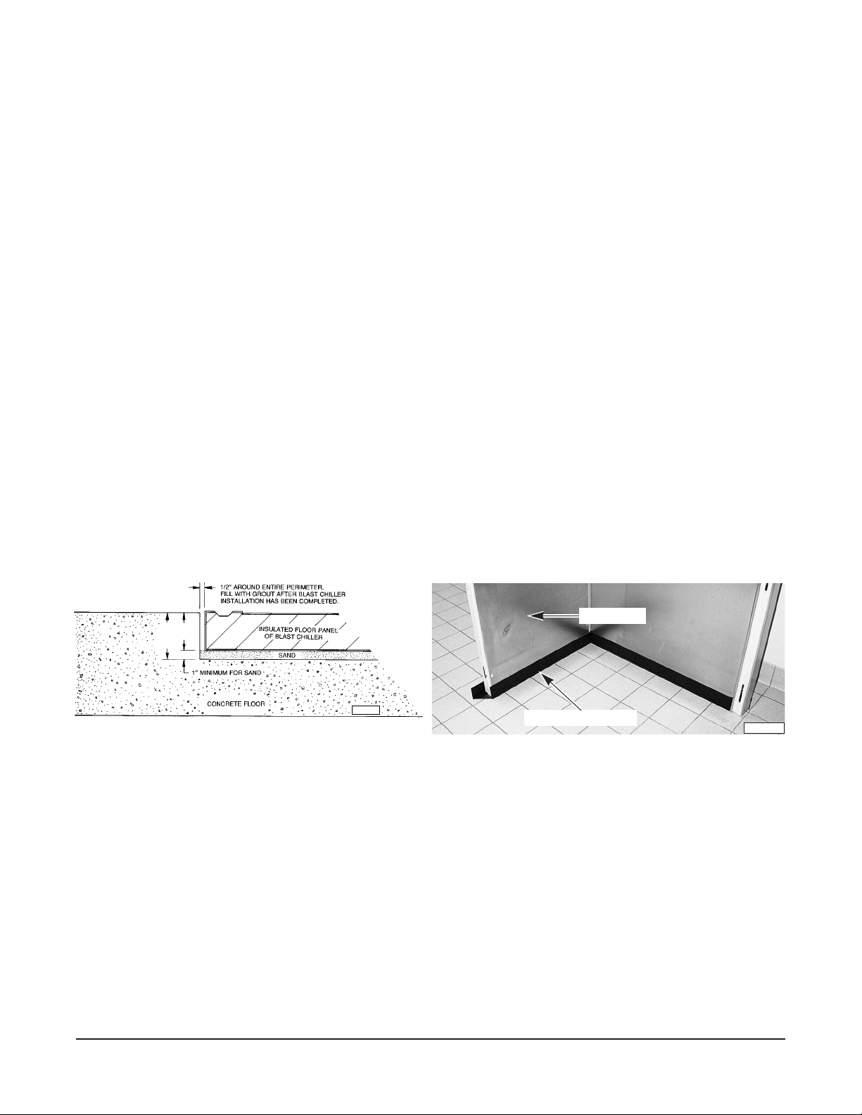
The floor panel is preferred to be installed in a recessed area so carts can roll flat into the Chiller. When
installing a recessed floor, a pit must be constructed in the concrete slab at least 4 inches in depth with
1
a
⁄2" clearance around the perimeter. The 4 inch depth is a minimum requirement. Floor panels are 3
inches in depth, the remaining inch is used for sand to facilitate leveling (Fig.1). The interior floor of
the cabinet should be even with the building floor.
INSTALLATION WITHOUT OPTIONAL INSULATED FLOOR PANEL
If no insulated floor panel is ordered, black vinyl screeds are provided. The wall panels of the chiller
cabinet are inserted in the black vinyl screeds during installation (Fig. 2). The chiller should be installed
on a smooth level surface. If necessary, further leveling may be provided by shimming between the
floor and wall panels.
WALL PANEL
PL-41153-1
MIN.
4”
3”
PL-53060
Fig. 1 Fig. 2
BLACK VINYL SCREED
INSTALLATION WITH OPTIONAL STAINLESS STEEL SHEET METAL FLOOR
The stainless steel sheet metal floor can be glued directly to the building floor before erection of the
QuickChill cabinet. Mark the 40" x 50" floor area where the QuickChill will be erected.
Make sure the floor is level before proceeding. If the floor is not level the wall panels will not be vertical,
the roof panels will not fit properly and the hinged door will not operate properly.
Both the building floor and the stainless steel sheet must be clean, dry and free from grease, oil, wax
or other surface contaminants.
Avoid glue contact with skin or eyes. Provide adequate ventilation. Do not breathe fumes. Follow the
glue manufacturer's instructions. Refer to assembly instructions shipped with the floor.
Allow at least 24 hours for the glue to set before beginning installation of the QuickChill cabinet.
– 5 –
Page 6
PANEL ASSEMBLY
4
4
4
4
4
4
4
4
4
4
4
4
4
4
4
4
4
4
4
4
4
4
4
4
4
4
4
4
4
4
4
4
4
4
4
4
4
4
4
4
4
4
4
4
4
4
4
4
4
4
4
4
4
4
4
4
4
4
4
4
4
4
4
4
4
4
4
4
12345678901234567890123456789012123
1
3
1
3
1
3
1
3
1
3
1
3
1
3
1
3
1
3
1
3
1
3
1
3
1
3
1
3
1
3
1
3
1
3
1
3
1
3
1
3
1
3
1
3
1
3
1
3
1
3
1
3
1
3
1
3
1
3
1
3
1
3
1
3
1
3
1
3
12345678901234567890123456789012123
7
7
7
6
6
6
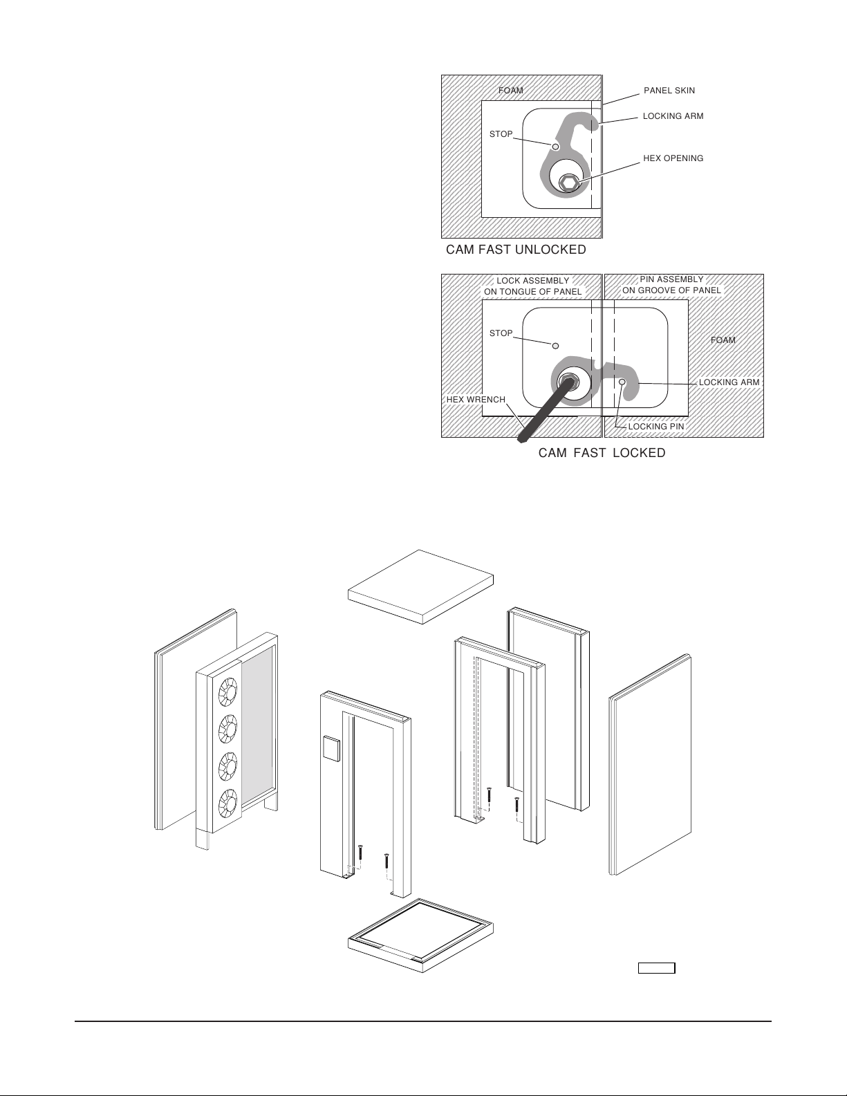
Each panel is locked in place with the Cam Fast
lock using the hex tool supplied (Fig. 3). Each wall
panel is locked to its adjacent sides and roof. When
an insulated floor panel is provided, wall panels are
cam locked to the insulated floor panel. If no
insulated floor panel is supplied, each wall panel
should be installed with its black vinyl screed fitted
on the bottom of the panel. Cam locks are turned
completely clockwise or counterclockwise (locking
arm retracted) before placing panels together; lock
3
by turning the hex tool
⁄4 turn in reverse. Access to
cam locks is provided inside the cabinet. Cam locks
should have their locking arm retracted before
placing panels together; lock by turning the hex
tool. Check wall panels for plumb occasionally
during assembly (Fig. 4). Assemble wall panels in
numerical order:
1 FLOOR (Optional)
2 REAR (Rear Door & Frame, Optional)
3 LEFT SIDE
4 RIGHT SIDE
5 COIL & FAN UNIT
6 DOOR & FRAME
7 CEILING
2345678901234567890123456789012123
2345678901234567890123456789012123
2345678901234567890123456789012123
2345678901234567890123456789012123
2345678901234567890123456789012123
2345678901234567890123456789012123
2345678901234567890123456789012123
2345678901234567890123456789012123
2345678901234567890123456789012123
2345678901234567890123456789012123
2345678901234567890123456789012123
2345678901234567890123456789012123
2345678901234567890123456789012123
2345678901234567890123456789012123
2345678901234567890123456789012123
2345678901234567890123456789012123
2345678901234567890123456789012123
2345678901234567890123456789012123
2345678901234567890123456789012123
2345678901234567890123456789012123
2345678901234567890123456789012123
2345678901234567890123456789012123
2345678901234567890123456789012123
2345678901234567890123456789012123
2345678901234567890123456789012123
2345678901234567890123456789012123
2345678901234567890123456789012123
2345678901234567890123456789012123
2345678901234567890123456789012123
2345678901234567890123456789012123
2345678901234567890123456789012123
2345678901234567890123456789012123
2345678901234567890123456789012123
2345678901234567890123456789012123
FOAM
STOP
CAM FAST UNLOCKED
2345678901234567890123456789012123
2345678901234567890123456789012123
2345678901234567890123456789012123
2345678901234567890123456789012123
2345678901234567890123456789012123
2345678901234567890123456789012123
2345678901234567890123456789012123
2345678901234567890123456789012123
2345678901234567890123456789012123
2345678901234567890123456789012123
2345678901234567890123456789012123
2345678901234567890123456789012123
2345678901234567890123456789012123
2345678901234567890123456789012123
2345678901234567890123456789012123
2345678901234567890123456789012123
2345678901234567890123456789012123
2345678901234567890123456789012123
2345678901234567890123456789012123
2345678901234567890123456789012123
2345678901234567890123456789012123
2345678901234567890123456789012123
2345678901234567890123456789012123
2345678901234567890123456789012123
2345678901234567890123456789012123
2345678901234567890123456789012123
2345678901234567890123456789012123
HEX WRENCH
2345678901234567890123456789012123
2345678901234567890123456789012123
2345678901234567890123456789012123
2345678901234567890123456789012123
2345678901234567890123456789012123
2345678901234567890123456789012123
2345678901234567890123456789012123
LOCK ASSEMBLY
ON TONGUE OF PANEL
STOP
234567890123456
234567890123456
234567890123456
CAM FAST LOCKED
PANEL SKIN
LOCKING ARM
HEX OPENING
234567890123456789012345678901212
234567890123456789012345678901212
PIN ASSEMBLY
234567890123456789012345678901212
234567890123456789012345678901212
ON GROOVE OF PANEL
234567890123456789012345678901212
234567890123456789012345678901212
234567890123456789012345678901212
234567890123456789012345678901212
234567890123456789012345678901212
234567890123456789012345678901212
234567890123456789012345678901212
234567890123456789012345678901212
234567890123456789012345678901212
234567890123456789012345678901212
234567890123456789012345678901212
234567890123456789012345678901212
234567890123456789012345678901212
234567890123456789012345678901212
234567890123456789012345678901212
234567890123456789012345678901212
234567890123456789012345678901212
234567890123456789012345678901212
234567890123456789012345678901212
234567890123456789012345678901212
234567890123456789012345678901212
234567890123456789012345678901212
234567890123456789012345678901212
234567890123456789012345678901212
234567890123456789012345678901212
234567890123456789012345678901212
234567890123456789012345678901212
234567890123456789012345678901212
23456789012345
23456789012345
234567890123456789012345678901212
LOCKING PIN
23456789012345
234567890123456789012345678901212
FOAM
LOCKING ARM
Fig. 3
7
2
3
5
6
1
Fig. 4
– 6 –
2
4
PL-53383
Page 7
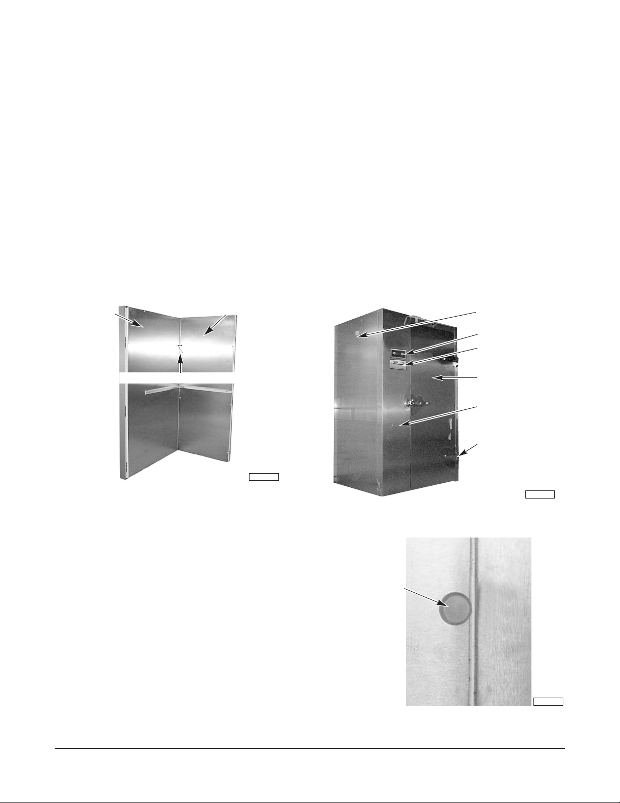
ASSEMBLY
PL-41550-1
CONTROLS
DOOR FRAME
HINGE
FRONT DOOR
LEFT SIDE PANEL
PRINTER(S)
PL-41113-1
PLUG BUTTON
If a 3" insulated floor is supplied, position and level floor panel first. Cam lock the wall panels to the
insulated floor panel. Black vinyl screeds are only supplied if the insulated floor panel is not ordered.
If the stainless steel sheet metal floor is to be installed, refer to the Technical Data / MSDS from the
adhesive manufacturer and follow the Assembly Instructions provided.
For all panels, peel off all vinyl coverings to expose the stainless steel surfaces inside and outside.
Lock wall panels to rear panel (Fig. 5). Cabinet must be plumb and level. Shimming may be installed
inside the screed, between the screed base and the bottom of the panel itself.
Install coil and fan section on the left side if the cabinet is right hinged and vice-versa. Two pre-attached
3
nuts are foamed inside the panel to accept
/8" bolts. Tighten the coil and fan section in place. Make
sure the gasket is in place around the back of the coil and fan section. This gasket should prevent the
condensate water from dripping behind the pan onto the cabinet floor.
If installing with black vinyl screeds, remove door from hinges of door frame. Remove the shipping
brace from the bottom of the door frame. Install the door frame by locking to side wall panels. If
insulated floor panel is present, cam lock to floor panel. Reinstall the door in its hinges (Fig. 6).
REAR PANEL
HEX WRENCH IN LOCKING HOLE
RIGHT SIDE PANEL
PL-41106-1
Fig. 5 Fig. 6
Position and cam-lock the roof to the wall and door frame
panels. Cabinets without an insulated floor panel must
have both sides of the door frame anchored to the
building floor (Fig. 4). Using a #19 drill bit appropriate for
the floor construction, make two .166" diameter holes in
the floor where each side of the door jam must be
anchored. Before fastening to the floor, make sure the
door frame is the same width at top and bottom and that
the door closes and fits well. Fasten the door jam to the
floor using the two cement screws, supplied. If the door
handle is out of adjustment, the door strike can be moved
in or out as follows: 1) Loosen both screws. 2) Move
strike in or out as needed. 3) Re-tighten both screws.
Install plug buttons in all cam lock holes (Fig. 7).
– 7 –
Fig. 7
Page 8
INTERNAL ELECTRICAL CONNECTIONS
0
0
0
0
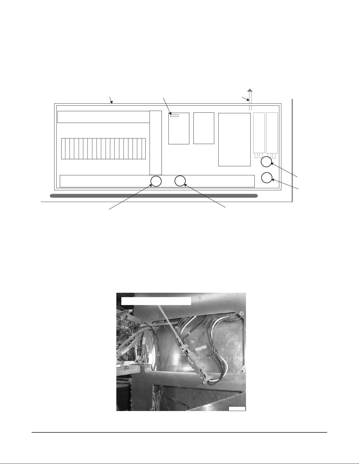
Remove the lid from the electrical box on top of the cabinet (Fig. 8). On the front of the cabinet, remove
two screws and swing the control panel open. On the front of the cabinet beside the control panel, turn
the black knob and swing the printer panel open.
From the top of the cabinet, inside the electrical box, insert a short plastic tube into the plastic tubes
foamed into the door frame panel. Refer to
TUBE #1 and TUBE #2 in Fig. 8.
ELECTRICAL BOX
234567890123456789
234567890123456789
234567890123456789
234567890123456789
TERMINAL [ CN2 ]
CABLE TO PRODUCT PROBES
PRINTER
POWER
SUPPLY
BOARD
CONTROL
POWER
SUPPLY
BOARD
I / O
BOARD
C
C
A
A
P
P
A
A
C
C
I
I
T
T
O
O
R
R
S
S
F
R
O
N
T
TUBE #1
TUBE #2
TUBE #4
LEFT SIDE OF CABINET
TUBE #3
Fig. 8
Push the power wires connector, labeled M, down through TUBE #1 (Fig. 8) to the recess behind the
control panel. Connect this connector (which includes 6 wires for the door switch, door frame heaters
and on-off switch) to its mating connector, labeled M (Fig. 9).
Feed the terminal for the two small black and two small red wires from the printer(s) up through the
empty TUBE #2 (Fig. 8) and connect it to terminal [ CN2 ] on the printer power supply board (Fig. 8).
JOIN POWER WIRE CONNECTORS
PL-41540-1
Fig. 9
– 8 –
Page 9
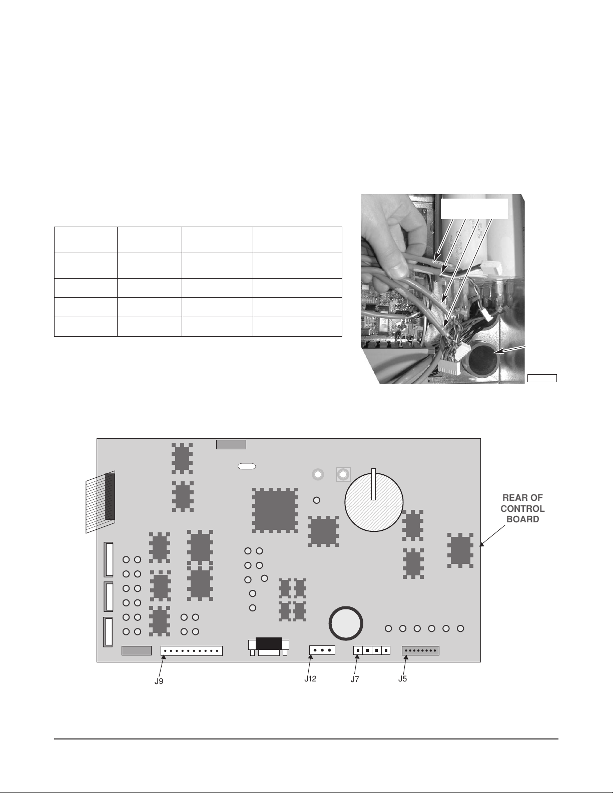
Push the four control cables with connectors [ J5 ], [ J7 ], [ J9 ] and [ J12 ] down TUBE #2. Refer to the
table below and Figs. 8 and 10. Connect the four cable connectors to the control board as shown in
Fig. 11. Attach the cables to the hinge with the wire-wrap provided.
Once all wires are connected and secured in the controller section, pull up the excess length so the
wires do not hang freely in the controller section (Fig. 9).
From the top electrical box, seal
TUBE #1 and TUBE #2 (Fig. 8) around the wires so warm air and foreign
matter do not reach down the tubes into the controller section. Duct seal (putty) is supplied with the
cabinet.
CONTROL CABLES
SELBACLORTNOC
NOLEBAL
ELBAC
YTIVAC
SEBORP
LIOC/RIA47JLIOC
RWP3 21JRWP
DRAOBO/I019JDRAOBO/I
FOREBMUN
SERIW
NOLEBAL
ROTCENNOC
85JSEBORPYTIVAC
NOLEBAL
DRAOBLORTNOC
J5, J7, J9, J12
TUBE #2
PL-41544-1
Fig. 10
J9
Fig. 11
– 9 –
J7
REAR OF
CONTROL
BOARD
J5J12
Page 10
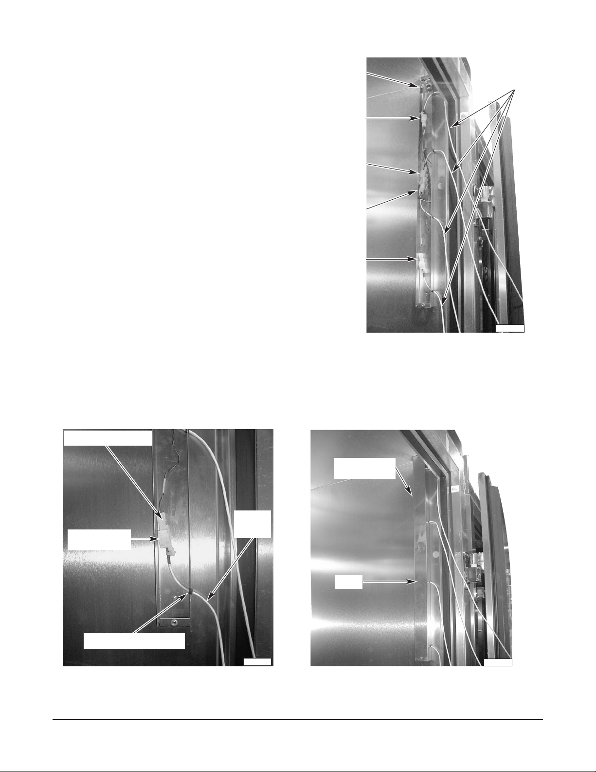
Product Probe Assembly
The product probe junction box is assembled on
the side wall panel behind the door hinges.
Remove the cover from the product probe junction
box. Push the product probe wires down from the
ceiling through the hole at the top of the product
probe juction box (Fig. 12). Extend the connectors
so Connector #1 is at the top, Connector #2 is
next, Connector #3 is below Connector #2, and
Connector #4 is at the bottom.
Place #1 product probe cable through the upper
slot in the product probe junction box so the
grommet on the cable fits the slot; connect the
connector end of the product probe cable to the #1
mating connector inside the product probe junction
box (Fig. 13). In the same manner connect the
second, third and fourth product probe cables to
the appropriate mating connectors: The #2
connector is second from top position, #3 is third
from top position and #4 is the bottom position
(Fig. 13).
Install the cover over the product probe junction
box using the two screws previously removed
(Fig. 14).
PRODUCT PROBE
JUNCTION BOX
CONNECTOR # 1
CONNECTOR # 2
CONNECTOR # 3
CONNECTOR # 4
PRODUCT
PROBE
CABLES
PL-41532-1
Fig. 12
From the top electrical box, seal the hole around the probe wires so warm air and foreign matter do not
reach down the hole into the product probe junction box. Duct seal (putty) is supplied with the cabinet.
MATING CONNECTOR # 4
PRODUCT PROBE
JUNCTION BOX
PRODUCT
PROBE
PRODUCT PROBE
CONNECTOR
GROMMET IN BOTTOM SLOT
CABLE
PL-41533-1
COVER
PL-41534-1
Fig. 13 Fig. 14
– 10 –
Page 11
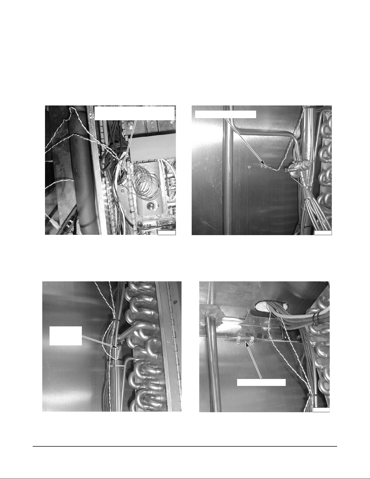
Temperature Control Sensors
Push the three refrigeration temperature control sensors down through
TUBE #3 (Fig. 8) from the
electrical box on top of the cabinet (Fig. 15). Install the three temperature control sensors in their proper
locations. Install the Air sensor (Fig. 16) on the side panel. Place the Coil sensor on the refrigeration
coil header (Fig. 17). Install the Over-temp sensor (Fig. 18) at the top of the left wall panel, inside the
cabinet.
TEMPERATURE CONTROL SENSORS:
DOWN THIS TUBE
AIR TEMPERATURE SENSOR
COIL
TEMPERTURE
SENSOR
PL-41546-1
Fig. 15 Fig. 16
OVER - TEMP SENSOR
PL-41547-1
Fig. 17 Fig. 18
– 11 –
PL-41549-1
Page 12

Fans and Defrost Heaters
Bring all connector blocks from the coil and fan section (fans and defrost heaters) up through
TUBE #3
and TUBE #4 to the electrical box (refer to Fig. 8, page 8). Mate the connector blocks with matching
connector blocks from the ceiling electrical box. Seal
TUBE #3 and TUBE #4 around the wires with proper
insulation. Duct seal (putty) is supplied with the cabinet.
If an optional rear pass-thru door is included, connect the additional mating connector blocks for the
door switch and door perimeter heater wires.
REFRIGERATION CONNECTIONS
On top-mounted, self-contained HQC135, all refrigeration lines are of the proper length. Assemble by
connecting the quick couplers. Brazing and welding are not required. Lines are pre-charged with
R-404A refrigerant.
On cabinets with remote condensing units, proceed with all refrigeration brazing that needs to be done
to bring suction and liquid lines out of the cabinet interior. Bring liquid line from the interior to the
solenoid valve installed on top of the cabinet. On standard units, refrigeration lines go out through the
ceiling hole. Seal hole around the lines with proper insulation. Duct Seal (putty) is supplied with the
cabinet.
Suction and liquid lines have to be installed between the cabinet and the remote compressor.
Refrigeration installation and start-up must then be done by a professional refrigeration technician,
using recognized industry-standard procedures.
DRAIN LINE INSTALLATION
The drain tube begins at the
7
/8" O.D. stainless steel connection at the bottom of the drain pan,
underneath the coil and fan section. If the drain outlet was not selected and drilled, make a hole in the
wall panel to exit the drain line. From the stainless steel connection, the drain should either go straight
to the front, straight to the rear, or straight to the side. Sufficient copper pipe is supplied to exit the
cabinet. Install this copper pipe by attaching it to the stainless steel connection using a small selftapping screw.
Once the drain exits the cabinet, it must be trapped per local code before being extended to an open
floor drain. The clearance area around the drain tube where it exits the panel wall must be sealed with
an NSF approved sealer.
INTERIOR FINISH DETAILS
Plates are provided on the top front of the coil and fan section. Move the plates up to cover the holes
on top of the coil and fan section. Run a bead of silicone sealant all around the coil and fan section,
between its stainless steel structure and the foamed walls. Install the cover for the coil and fan section
using the six wing bolts, supplied. The square openings should be placed in front of the fan units —
louvers, in front of the coil. Fans will not start if the cover is not in its proper position.
INSTALLATION OF REMOTE ALARM (
OPTIONAL)
The Chiller provides a connection for a remote alarm that operates when the buzzer sounds on
completion of a chill cycle. This output is a set of normally open relay contacts which close when an
alarm occurs. Connections are made to terminals 5 and 6 located in the junction box on the roof per
the wiring diagram and these restrictions:
1. Maximum remote alarm rating: 120V at 2 amps resistive or 100 watt incandescent lamp.
2. Connection must be made with 600 volt insulated wire suitable for supply voltage. Do not use bell
wire, lamp cord or similar type wire.
– 12 –
Page 13

ELECTRICAL CONNECTIONS
WARNING: ELECTRICAL AND GROUNDING CONNECTIONS MUST COMPLY WITH THE
APPLICABLE PORTIONS OF THE NATIONAL ELECTRICAL CODE AND/OR OTHER LOCAL
ELECTRICAL CODES.
WARNING: DISCONNECT ELECTRICAL POWER SUPPLY AND PLACE A TAG AT THE
DISCONNECT SWITCH INDICATING THAT YOU ARE WORKING ON THE CIRCUIT.
Whether the condensing unit is remote or mounted on top of the cabinet (available on HQC135 only),
there is a separate power supply for the condensing unit. There is no electrical connection between
the cabinet electrical box and the condensing unit electrical box.
ATADLACIRTCELE
ledoMrosserpmoC/tenibaC.P.Hrh/UTBesahP/ztreH/stloV
.cte,snaF&slortnoC:tenibaC
delooC-riAroodnI
rosserpmoCcitemreH
etomeRrodeniatnoC-fleS
delooC-retaWroodnI
531CQH
rosserpmoCcitemreH
etomeRrodeniatnoC-fleS
delooC-riAroodnI
ylnOetomeRrosserpmoCcitemreH-imeS
delooC-retaWroodnI
ylnOetomeRrosserpmoCcitemreH-imeS
roodtuO
ylnOetomeRrosserpmoCcitemreH-imeS
.a.n.a.n1/06/042-802/0219.0102
:wolebtsilehtmorfrosserpmocenosulP
1
3
/
4
1
3
/
4
3008,423/06/032-8029.1203
3006,123/06/032-8025.5152
3004,523/06/032-8020.1203
004,02
007,91
muminiM
tiucriC
yticapmA
SPMA
1/06/032-8021.9204
3/06/032-8021.0203
3/06/0846.951
1/06/032-8026.3204
3/06/032-8026.4152
3/06/0840.851
mumixaM
esuF
eziS
SPMA
.cte,snaF&slortnoC:tenibaC
delooC-riAroodnI
etomeRrosserpmoCcitemreH
delooC-riAroodnI
002CQH
roodtuO
delooC-retaWroodnI
delooC-retaWroodnI
etomeRrosserpmoCcitemreH-imeS
etomeRrosserpmoCcitemreH-imeS
etomeRrosserpmoCcitemreH
etomeRrosserpmoCcitemreH-imeS
.a.n.a.n1/06/042-802/0219.0102
:wolebtsilehtmorfrosserpmocenosulP
1/06/032-8020.2406
5009,23
5008,53
5086,93
5545,03
5579,93
3/06/032-8025.9254
3/06/0848.4102
3/06/032-8023.2305
3/06/0845.5102
3/06/032-8021.7306
3/06/0847.7152
1/06/032-8027.8306
3/06/032-8022.6204
3/06/0845.3102
3/06/032-8029.7205
3/06/0841.3102
CAUTION: Before connecting the electrical power to the service connection box, measure all voltages
with a voltmeter. L1 to Neutral and L2 to Neutral should measure approximately 120 VAC.
– 13 –
Page 14

INSTALLATION — REMOTE CONDENSING UNITS
Prior to installing the condensing unit, test the electrical service to assure that it agrees with the
specifications on the data plate located on the condensing unit frame.
GENERAL
The Model HQC135 Chiller can be purchased with a remote condensing unit. The HQC200 will always
1
be provided with a remote condensing unit. Condensing unit sizes are 3 or 3
HP for HQC200. Condensing units are available for indoor air-cooled, indoor water-cooled or outdoor
5
/4 HP for HQC135 and
application, to be specified at time of order. Compressor is available in hermetic or semi-hermetic
types for HQC135 and HQC200.
DUE TO THE VARIED NATURE, COMPLEXITY AND UNIQUENESS OF REMOTE CONDENSING
UNIT INSTALLATIONS, THE HOBART WARRANTY DOES NOT COVER REMOTE INSTALLATION
WORK AND DOES NOT COVER CONDENSING UNITS SUPPLIED BY OTHERS.
ELECTRICAL CONNECTIONS
WARNING: ELECTRICAL AND GROUNDING CONNECTIONS MUST COMPLY WITH THE
APPLICABLE PORTIONS OF THE NATIONAL ELECTRICAL CODE AND/OR OTHER LOCAL
ELECTRICAL CODES.
WARNING: DISCONNECT ELECTRICAL POWER SUPPLY AND PLACE A TAG AT THE
DISCONNECT SWITCH TO INDICATE THAT YOU ARE WORKING ON THE CIRCUIT.
Install electrical conduit and wiring (not supplied) from the power supply to the terminal junction box
on the condensing unit. Proper supply voltage, maximum fuse/circuit breaker sizes and minimum
circuit amperage can be found on the condensing unit data plate. On outdoor condensing units, wiring
must be encased in watertight conduit and use watertight fittings.
It is recommended that a disconnect switch (not supplied) be located near the remotely installed
condensing unit for installing or servicing.
Refer to page 13.
CONDENSER RECOMMENDATIONS
For indoor installations, place the condensing unit in a cool, dry place that is easily accessible for
installation, cleaning and maintenance. The condenser must be located a minimum of 2 feet from a
wall or obstruction. For air-cooled condensing units located in machine rooms or air restricted areas,
ventilation is needed to dissipate the heat produced by the condenser. The condenser heat varies
during the chilling cycle but could be considered for ventilation purposes to be as follows:
1
3 or 3
/4 HP Condensing Unit 50,000 BTU/h
5 HP Condensing Unit 73,000 BTU/h
– 14 –
Page 15

PIPE SIZING GUIDELINES
Piping design and line sizing is the responsibility of the installer. The following table can be used as
a guideline. The ‘Net Distance to Condensing Unit’ column allows 50% of the Distance for the
equivalent restriction to refrigerant flow caused by elbows. We recommend the installer minimize
restriction to refrigerant flow by incorporating the following features in their design: Use fewer elbows;
use long radius elbows when possible; use 45° elbows instead of 90° elbows, if possible. A vertical
suction riser greater than 3 to 4 feet in height should have a P trap at the base to facilitate oil return
up the riser. For long vertical risers, an additional P trap is recommended for each 20 feet of riser to
assure proper oil movement.
tnelaviuqEsseL
ledoM
531CQH
002CQH
htgneLtnelaviuqElatoT
teeF54nahTsseL teeF51
teeF003ot54morF teeF001
teeF003revO teeF001
teeF57nahTsseL teeF52
teeF573ot57morF teeF521
teeF573revO teeF521
ecnawollAhtgneL
swoblErof
ecnatsiDteN
tinUgnisnednoCot
teeF03nahTsseL
teeF002ot03morF1
teeF002revO1
teeF05nahTsseL1
teeF052ot05morF1
teeF052revO1
eniLnoitcuS
eziS
7
/8"
1
/8"
3
/8"
1
/8"
3
/8"
5
/8"
eniLdiuqiL
eziS
3
/8"
1
/2"
1
/2"
1
/2"
1
/2"
5
/8"
Additional information is available from your compressor manufacturer's system design manual.
OUTDOOR CONDENSING UNITS
Outdoor condensing units are equipped with weather resistant outdoor covers, crankcase heaters and
head pressure valves to control the flow of refrigerant through the condenser.
Refrigerant charging of the system in ambients above 70°F requires additional charging equal to the
pounds necessary to flood the condenser under low ambient conditions, as defined in the chart below:
MODEL CONDENSING UNIT APPROXIMATE ADDITIONAL
(HP) R-404A CHARGE
HQC135 3 or 31/4 8 lbs
HQC200 5 15 lbs
Charging of the system with refrigerant in ambients below 70°F requires caution to prevent overcharging
since the pressure control valve will already be partially functioning and the amount of additional
charge must be determined.
VALVE AND PRESSURE SETTINGS
LOW PRESSURE CONTROL SETTING
(Refrigerant R-404A)
Low Pressure Cut-In 30 psig
Low Pressure Cut-Out 10 psig
The ideal superheat at the evaporator outlet is 8 – 10°F.
– 15 –
Page 16

WATER COOLED CONDENSING UNITS
Water cooled condensing units are equipped with water valves which control the rate of water flow
through the condenser based upon compressor head pressure. The maximum allowable working
pressure on these valves is 150 psig, so a pressure reducing valve may be required. The location of
the condensing unit should be such that it will not be exposed to ambient temperatures below freezing.
A chart of water flow requirements for condensing units (page 17) is based upon incoming water
temperature and is expressed in gallons per hour per 1,000 BTU/hr refrigeration.
BTU/hr capacities are:
MODEL HP BTU/HR CAPACITY
HQC135 3 or 31/4 24,800 at 10°F Suction and 105°F Condensing
HQC200 5 35,800 at 10°F Suction and 105°F Condensing
The water cooled condensing units may be plumbed in series for use with city water supplies or
plumbed in parallel for connection to a cooling tower. All water cooled condensing units are refrigerant
cooled, and therefore should have superheat settings to maintain return gas temperatures not to
exceed 65°F. For additional information, refer to Copeland Technical Bulletin AE 1174-R6, dated
January 1, 1985. A copy is available through your sales representative.
– 16 –
Page 17

WATER FLOW REQUIREMENT FOR COPELAND WATER COOLED CONDENSING UNITS *
Gallons per hour per 1,000 BTU/hr (Net)
Temperature Difference, Entering Water to Condensing
20
°F T.D. 30°F T.D.
Operating
Conditions Series Parallel Series Parallel
Water Flow Water Flow Water Flow Water Flow
90°F Condensing
45°F Evap. 8.1 10.1 5.5 6.8
15°F Evap. 8.9 11.1 6.0 7.5
-10°F Evap. 10.0 12.5 6.8 8.5
100°F Condensing
45°F Evap. 8.2 10.3 5.6 6.9
15°F Evap. 9.2 11.5 6.2 7.8
-10°F Evap. 10.4 13.0 7.1 8.8
110°F Condensing
45°F Evap. 8.5 10.5 5.7 7.1
15°F Evap. 9.5 11.8 6.4 8.0
-10°F Evap. 10.9 13.5 7.4 9.2
* Reproduced from Copeland Technical Bulletin AE 1174-R6, dated 1/1/85.
– 17 –
Page 18

CONTROLS (Fig. 19)
START-UP
OPERATION
MAIN MENU 08:05:01
BY TEMP BY PROD
BY TIME
MORE
Fig. 19
SmartChill
HQC135
INITIALIZING
VERSION 1.00
The screen at left is displayed when the chiller is first
turned on.
OVER TEMPERATURE
If CAUTION HI AIR 160°F displays, turn the chiller off, open the door and allow the excessively high
temperature and humidity to evacuate the chamber. Then restart the chiller and resume the chill cycle.
Choose a selection from the menu that appears on the control’s display by pressing the button
graphically connected to the display prompt. Four buttons are arranged on the left and four on the right.
For example, to select By Temp, press the second button on the left.
PROBES
During a chill cycle, insert probes in pans of food to monitor
temperatures. Probes should not touch bottom of pan. Place probe
in the middle of the food for best temperature indication.
Probe 1 is the upper probe in the cabinet (Fig. 20). Probe 2 is next,
followed by Probe 3. Probe 4 is at the bottom.
DOOR SWITCH
CHILLING AIR: 14°F
1 159
2 154°F 157°F 4
0:00:03 ADD/REMOVE
°F 156°F 3
Fig. 20
When the door is opened, the door switch shuts off fans and DOOR OPEN displays. If the door is open
for 30 seconds, the refrigerant valve closes. If the door is open for 120 seconds (or the
D
OOR OPEN
time setting on page 34), a buzzer sounds. After the door closes, timer and chiller operations resume.
FAN DOOR SWITCH
A fan door switch also shuts the fans and refrigerant valve off if the metal fan grill is not properly
fastened in place. A notice displays: WARNING !!! FAN DOOR IS OPEN. CALL HOBART SERVICE
FOR REPAIR. If the operator and supervisor cannot shut the interior fan door, contact Hobart Service.
The chiller will not operate with the fan door open.
– 18 –
Page 19

PRINTER SUPPLIES
Printer supplies are available from your local Hobart sales and service office.
The standard printer uses 2
1
/4" thermal printer paper, Hobart Part Number 434409, per roll. Minimum
order quantity: 50 rolls per 1 case. Roll length is 80 feet.
The optional label printer uses peel-off label stock, Hobart Part Number 434408, per roll. Minimum
order quantity: 50 rolls per 1 case. Each roll contains 225 labels.
LOADING ROLL STOCK ONTO THE PRINTERS (Fig. 21)
Plain Thermal Paper
A roll is placed on the printer shaft. The ends of the printer shaft are installed in the two roll holders.
Follow the diagram on the back of the printer so the paper is correctly fed through the printer. The
bottom of the roll feeds down over the feeder bar and into the printer. The printer mechanism will
automatically advance the paper through the slot. If this is done properly, the correct side of the thermal
paper can be activated by the thermal printer head.
Adhesive-Backed Label Stock for Optional Label Printer
A roll of label stock is placed on the printer shaft. The ends of the printer shaft are installed in the two
roll holders. Follow the diagram on the back of the printer so the paper is correctly fed through the
printer. The bottom of the roll feeds down over the feeder bar and into the printer. The printer
mechanism will automatically advance the label paper through the slot.
PL-41530
Fig. 21
WHEN POWER IS RESTORED AFTER A POWER INTERRUPTION
CYCLE INTERRUPTED:
FROM 3/15/01 10:17
UNTIL 3/15/01 13:22
CONT. CHILLING OK
The display indicates the time and duration of any power
interruption that occurs during a Chill cycle. The operator can
make appropriate decisions about food stored in the chiller.
Press OK to continue. A
CYCLE INTERRUPT
Then, the system resumes at the previous activity. Return to the
Main Menu for any other action.
NOTE: The display indicates
CYCLE INTERRUPTED
the power switch is turned off and on during any chilling, holding,
or freezing mode. Always stop chilling by returning to the Main
Menu before turning the power switch off.
– 19 –
report is printed.
any time
Page 20

MAIN MENU
MAIN MENU 08:05:01
BY TEMP BY PROD
BY TIME
MORE
MAIN MENU 08:06:01
HOLD PROD PRINT
DEFROST SETUP
BACK
BY TEMP —
BY TEMPERATURE
TYPE: CHILL
↓TARGET TEMP: 37
MAIN START
BY TEMPERATURE
TYPE: SOFT CHILL
↓TARGET TEMP: 37
MAIN START
❄
CHILLING AIR: 14°F
1 159
2 154°F 4
0:00:03 ADD/REMOVE
Chill Cycle is complete when any (or all) product probe(s) reaches the Target Temp.
From the Main Menu, select BY TEMP.
°F↑
°F↑
• Select the Type: CHILL or SOFT CHILL.
LEDOMPMETYB
531CQH
002CQH
LLIHC73 °F04OT33 ° *F
LLIHCTFOS73 °F04OT33 ° *F
55otdednetxeebnacegnaR* ° .53egapees—derisedfirosivrepusybF
TESERPYROTCAF
PMETTEGRAT
EGNAR
• To adjust the TARGET TEMP: Press ↓ or ↑.
• Insert probes in product — smart probes sense
temperature of product and are automatically selected.
• Close the door.
• To begin Chilling, select START.
(MAIN returns to the Main Menu.)
°F 156°F 3
• To add more product while chilling: Open door; insert
probe in product; close door; press ADD/REMOVE.
SELECT PROBE:
1 159°F 156°F 3
2 154°F 4
0:00:07 CONTINUE
CHILLING AIR: 14°F
1 159
2 154°F 157°F 4
0:00:19 ADD/REMOVE
CHILLING AIR: 14°F
1 39°F DONE 3
2 44°F 48°F 4
1:16:01 MUTE
°F 156°F 3
• If any probes are
O
FF
, select the desired probe(s).
• Press CONTINUE.
• The chill time displays in the lower left corner —
Hr: Min: Sec.
☛ A probe has reached the target temperature.
• Press MUTE or select the ‘done’ probe’s number to
silence the buzzer.
(This step is repeated as each probe reaches the
target temperature; see next page.)
– 20 –
Page 21

CHILLING AIR: 14°F
1 39°F DONE 3
2 44°F 48°F 4
1:16:01 ADD/REMOVE
• Press ADD/ REMOVE.
• If all probes are ‘done,’
the display goes to
HOLDING.
HOLDING AIR: 37°F
1 DONE DONE 3
2 DONE DONE 4
1:16:01 ADD/REMOVE
SELECT PROBE:
1 39°F DONE 3
2 44°F 48°F 4
1:16:08 CONTINUE
SELECT PROBE:
1 39°F REMOVE 3
2 44°F 48°F 4
1:16:28 CONTINUE
PRINT PROBE #3
NONE RECORD
CHILLING AIR: 13°F
1 39
2 44°F 48°F 4
1:17:42 ADD/REMOVE
°F 3
• Select the ‘done’ probe’s number to remove it.
• Remove all product associated with the ‘done’ probe.
• Select any other probe’s
STOP CYCLE ON #2
number to stop cycle
and remove it. Answer
YES or NO.
REMOVE PRODUCT?
NO YES
• Press CONTINUE.
• Select NONE to continue chilling with no report.
• Or, select RECORD to print a Chill Report on Probe
#3. Refer to the alternate Print Probe menu at the
bottom of this page.
CHILLING AIR: 14°F
1 DONE 3
2 40°F 44°F 4
1:19:02 MUTE
PRINTING
PLEASE WAIT...
PRINT PROBE #3
RECORD
LABEL
NONE BOTH
• Repeat from ☛ as each probe reaches the target
temperature.
• When all probes are done, return to the Main Menu.
• If equipped with the optional label printer, an alternate
Print Probe menu, shown at left, permits the choice of
printing . . . RECORD, LABEL or BOTH . . . types
of reports.
– 21 –
Page 22

MAIN MENU
MAIN MENU 08:05:01
BY TEMP BY PROD
BY TIME
MORE
MAIN MENU 08:06:01
HOLD PROD PRINT
DEFROST SETUP
BACK
BY TIME —
BY TIME
TYPE: CHILL
↓CYCLE TIME: 01:30↑
MAIN START
BY TIME
TYPE: SOFT CHILL
↓CYCLE TIME: 01:30↑
MAIN START
❆
Timer counts down until cycle is done.
From the Main Menu, select BY TIME.
• Select the Type: CHILL or SOFT CHILL.
• To adjust the CYCLE TIME: Press ↓ or ↑.
• To begin Chilling, select START.
DOOR OPEN AIR: 14°F
1 159
2 154°F 157°F 4
1:30:00 STOP/RESET
°F 156°F 3
• Close the door.
• If probes are utilized, they will display temperature but
• Select STOP/ RESET to obtain these menu items:
BY TIME
ADD 30 MINUTES
RESET TIMER
STOP CONTINUE
CHILLING AIR: 14°F
1 159
2 154°F 157°F 4
1:29:57 STOP/RESET
°F 156°F 3
• Time Remaining displays in the lower left corner —
LEDOMPMETYBGNITTESEMITLAITINIEGNAREMIT
ro531CQH
002CQH
LLIHC03:1000:42OT10:00
LLIHCTFOS03:1000:42OT10:00
(MAIN returns to the Main Menu.)
will have no effect on the chilling process.
ADD 30 MINUTES adds 30 minutes to the timer.
°
RESET TIMER re-starts at the original time setting.
°
CONTINUE resumes the cycle at the time remaining.
°
STOP allows a report to be printed and then returns
°
to Main Menu.
Hr: Min: Sec.
HOLDING AIR: 14°F
1 39°F 4 2 °F 3
2 44°F 40°F 4
0:00:00 MUTE
HOLDING AIR: 14°F
1 39°F 42°F 3
2 44°F 40°F 4
0:00:11 STOP/RESET
☛ The timer has counted down to 0:00:00. The chiller
changes to HOLDING Mode.
• Press MUTE to silence buzzer.
• The total time since the cycle was finished is displayed
— Hr: Min: Sec.
• Remove all chilled product.
• Press STOP/ RESET.
– 22 –
Page 23

PRINT
NONE RECORD
PRINTING
PLEASE WAIT...
MAIN MENU
PRINT
RECORD
LABEL
NONE BOTH
• Select NONE to continue without printing.
• Select RECORD to print a Chill Report. If equipped
with the optional label printer, refer to the alternate
Print menu below. NOTE: Chilling BY TIME does not
retain Product Probe temperature data in memory and
will not print
TEMP vs. TIME information.
• After printing or selecting NONE, return to the Main
Menu.
• If equipped with the optional label printer, an alternate
Print menu, shown at left, permits the choice of printing
. . . RECORD, LABEL or BOTH . . . types of reports.
– 23 –
Page 24

MAIN MENU
MAIN MENU 08:05:01
BY TEMP BY PROD
BY TIME
MORE
MAIN MENU 08:06:01
HOLD PROD PRINT
DEFROST SETUP
BACK
BY PROD —
SELECT USER:
↓TIM SMITH ↑
BACK SELECT
SELECT PRODUCT:
↑CHICKEN PARTS
↓SOUP VEGETABLE
Recalls programmed chill parameters for the product, either BY TEMP or BY TIME.
From the Main Menu, select BY PROD.
• If two or more users have been entered, use the ↓ or
↑ keys until the user’s name is displayed. Then press
SELECT.
• The two products displayed are the most recently
chilled products. The ↓ key will access the next
MAIN MENU
enabled product from the product list, etc.
• Press the
key beside the product name to recall that
product’s chill parameters.
(MAIN returns to the Main Menu.)
NOTE: If the product you wish to select is
on the Product List on page 26 but is not
available from the Select Product screen, it
needs to be enabled. The Supervisor should
refer to Setup Products, page 28.
– 24 –
Page 25

If the selected product was set to chill BY TEMP:
CHILLING AIR: 14°F
1 159
2 154
0:00:03 ADD/REMOVE
CHILLING AIR: 14°F
1 159
2 154
1:29:57 STOP/RESET
°F 3
°F 4
If the selected product was set to chill BY TIME:
°F 156°F 3
°F 154°F 4
• Follow the cycle run information on pages 20 – 21
beginning at
• Follow the cycle run information on pages 22 – 23
beginning at
❄.
❆.
NOTE: If the chill parameters for the product
you selected do not chill the way you want,
the product’s chill settings need to be edited.
The Supervisor should refer to Setup
Products, page 28.
– 25 –
Page 26

PRODUCT LIST
Any product from the PRODUCT LIST can be chilled using the BY PROD mode, once it has been
enabled in Setup Products (page 28). Only CHICKEN PARTS and SOUP VEGETABLE are initially
enabled as preset at the factory.
NOTE: All products are initially set in the BY TEMP – CHILL mode with a Target Temp of 37°F and
Hold Temp of 37°F.
ASPARAGUS LAMB SALAD POTATO
BEANS LASAGNA SANDWICHES
BEANS BAKED LIVER SAUCE
BEEF MACARONI & CHEESE SAUCE CHEESE
BEEF CREAMED MACARONI & GROUND BEEF SAUCE MEAT
BEEF ROAST MEAT SAUCE TOMATO
BEEF TIPS MEAT GROUND SAUSAGE
BROCCOLI MEAT LOAF SOUP BEAN
CABBAGE STUFFED MEAT SLICED SOUP CREAM OF CELERY
CARROTS MEAT WITH SAUCE SOUP POTATO
CASSEROLE OATMEAL SOUP TOMATO
CEREAL COOKED PASTA SOUP VEGETABLE
CHICKEN & DUMPLINGS PEAS SPAGHETTI
CHICKEN PARTS PEPPERS STUFFED STARCH DISH
CHICKEN POT PIE PORK STEAK
CHOWDER CORN PORK CHOPS STEAK CHOPPED
COLE SLAW POTATO MASHED STEAK SALISBURY
COMBINATION DISHES POTATO SLICED STEAK SWISS
CORN POTATOES STEW
DRESSING CORNBREAD POTATOES SCALLOPED STEW BEEF
FISH BAKED POULTRY TACO MEAT
FISH BREADED POULTRY SLICED TUNA SALAD
GRAVY POULTRY WITH SAUCE TURKEY BREAST
GRITS PRE PLATES TURKEY ROAST
HAM RICE VEAL CHOPS
JELLO ROAST WHOLE VEGETABLES
– 26 –
Page 27

MAIN MENU 08:05:01
BY TEMP BY PROD
BY TIME
MORE
MAIN MENU 08:06:01
HOLD PROD PRINT
DEFROST SETUP
BACK
HOLD PROD —
HOLDING AIR: 34°F
1 37
2 37
0:00:04 EXIT
DEFROST
READY TO DEFROST
REMOVE FOOD
CANCEL START
DEFROSTING
COIL 12
TIME REMAINING 19:52
EXIT
After Chilling or when selected, runs the chiller like a regular refrigerator.
From the Main Menu, select MORE and HOLD PROD.
(Temperatures are indicated for air and probes.)
°F 3 7 °F 3
°F 37°F 4
(Timer indicates the run time. No printed reports are
available.)
(EXIT returns to the Main Menu; however, Hold mode
continues until another selection is made.)
NOTE: DEFROST starts automatically after 6 hours of chilling but only if
operating in Holding mode.
From the Main Menu, select MORE and DEFROST.
• To begin Defrosting, remove food and select START.
(CANCEL returns to the Main Menu.)
°F
• The DEFROST cycle runs 20 minutes or until the Coil
Temperature reaches 50°F.
(EXIT returns to the Main Menu.)
PRINT —
DEFROST
NOT REQUIRED
• If DEFROST NOT REQUIRED is displayed, return to
Main Menu is automatic.
Once a chill cycle is done, data can be printed.
From the Main Menu, select MORE and PRINT.
PRINT CYCLE #__
PROBE #_ MM/DD HH:mm→
←BACK SELECT NEXT→
MAIN MENU PRINT
• The last chill cycle displays Probe # (if BY TEMP),
MM/DD (month/day), and HH: mm (hour: minute).
Probe # will not display if the chill cycle was BY TIME.
• Select the Cycle you want to print by pressing ← (for
previous) and → (for next).
PRINT PROBE #_
RECORD
LABEL
NONE BOTH
• Press PRINT.
(MAIN returns to the Main Menu.)
• To print, select RECORD, LABEL or BOTH. After
printing, the display returns to the Main Menu.
(NONE returns to the Main Menu.)
– 27 –
Page 28

SETUP
MAIN MENU 08:05:01
BY TEMP BY PROD
BY TIME
MORE
From the Main Menu, select MORE and SETUP.
MAIN MENU 08:06:01
HOLD PROD PRINT
DEFROST SETUP
BACK
SELECT SUPERVISOR:
↓PRESET SUPERVISOR↑
↓PASSWORD (PIN): 00↑
CANCEL ENTER
SELECT SUPERVISOR:
↓TIM SMITH ↑
↓PASSWORD (PIN): 07↑
CANCEL ENTER
PRODUCTS
SETUP 09:04:11
PRODUCTS SYS PAR
USERS
MAIN MENU
SETUP PRODUCTS:
ENABLE/DISABLE
EDIT SETTINGS
↓ASPARAGUS ↑
TYPE: CHILL
↓TARGET TEMP: 37
BY TEMP MORE
BACK
PRODUCT SELECTION:
↓ASPARAGUS ↑
ENABLED: NO
BACK
°F↑
• When you first enter SETUP, only Preset Supervisor is
available. On the PASSWORD (PIN) line, use the ↓ or
↑ keys until 57 is displayed as the Preset Supervisor’s
Personal Identification Number. Press ENTER.
• If users have already been set up, select the
supervisor’s name using the ↓ or ↑ keys. On the next
line, use the ↓ or ↑ keys to enter their Password (or
Personal Identification Number). Press ENTER.
• From Setup, select PRODUCTS.
• Select ENABLE / DISABLE to choose what products
are enabled from the Product List. Only an enabled
product is available to chill BY PROD. Go to ☞.
• Select EDIT SETTINGS to adjust chill parameters for
any product that has already been enabled. Go to ➢.
(BACK returns to SETUP.)
☞ After selecting ENABLE / DISABLE, use the ↓ or ↑
keys to select a product from the list. Press
to
change ENABLED: NO to YES to enable the product
or to change YES to NO to disable it. The two most
recently chilled products cannot be disabled.
• BACK saves the ‘enabled’ and returns to SETUP
PRODUCTS.
➢ After selecting EDIT SETTINGS, use the ↓ or ↑ keys
to select a product. Finish all ⊗ steps to change any
settings.
⊗ Select the Type: CHILL or SOFT CHILL.
↓ASPARAGUS ↑
↓HOLD TEMP: 37
BACK SAVE
°F↑
CANCEL
⊗ Select BY TEMP or BY TIME. Use the ↓ or ↑ keys to
adjust the TARGET TEMP if BY TEMP is displayed, or
to adjust the CYCLE TIME if BY TIME is displayed.
⊗ Select MORE and use the ↓ or ↑ keys to adjust the
HOLD TEMP.
⊗ Press SAVE to keep the changes and return to SETUP
PRODUCTS. (CANCEL returns to SETUP
PRODUCTS without saving the changes. BACK
returns to the previous screen).
– 28 –
Page 29

SETUP
MAIN MENU 08:05:01
BY TEMP BY PROD
BY TIME
MORE
From the Main Menu, select MORE and SETUP.
MAIN MENU 08:06:01
HOLD PROD PRINT
DEFROST SETUP
BACK
USERS
SELECT SUPERVISOR:
↓PRESET SUPERVISOR↑
↓PASSWORD (PIN): 00↑
CANCEL ENTER
SELECT SUPERVISOR:
↓TIM SMITH ↑
↓PASSWORD (PIN): 07↑
CANCEL ENTER
SETUP 09:04:11
PRODUCTS SYS PAR
USERS
MAIN MENU
SETUP USERS:
ADD DELETE ALL
EDIT/DELETE
BACK
SELECT USER #1:
↓TIM SMITH ↑
EDIT DELETE
BACK
ENTER NAME:
↓_ ↑
BACK NEXT
CANCEL ENTER
• When you first enter SETUP, only Preset Supervisor is
available. On the PASSWORD (PIN) line, use the ↓ or
↑ keys until 57 is displayed as the Preset Supervisor’s
Personal Identification Number. Press ENTER.
• If users have already been set up, select the
supervisor’s name using the ↓ or ↑ keys. On the next
line, use the ↓ or ↑ keys to enter their Password (or
Personal Identification Number). Press ENTER.
• From Setup, select USERS.
(MAIN MENU returns to the Main Menu.)
• Press ADD to add a user to the roster. The first user
entered will automatically be given Supervisor status.
(DELETE ALL removes all users from the roster.)
(EDIT / DELETE allows a user’s security level or PIN
to be revised or the user removed from the roster.)
• To ENTER NAME: Press the ↓ or ↑ keys until the first
letter of the user’s name is entered; then, press NEXT
to move the cursor one space to the right. Repeat this
step until all letters of the user’s name are entered.
BACK moves the cursor one space to the left to edit.
• Press ENTER to save the user’s name, as displayed.
(CANCEL aborts the process.)
SETUP USER:
SECURITY LEVEL:OPER
↓PASSWORD (PIN): 00↑
ENTER
• Press
to change the security level from OPER to
SUPV or from SUPV to OPER. See above, operator
level security is only available after the first user is
entered.
• Use the ↓ or ↑ keys to select the user’s PASSWORD
(PIN).
• Press ENTER to save the user’s security level and
PIN. Return to SETUP USERS.
– 29 –
Page 30

SYS PAR
• From the Main Menu, select MORE and SETUP.
MAIN MENU 08:05:01
BY TEMP BY PROD
BY TIME
MORE
MAIN MENU 08:06:01
HOLD PROD PRINT
DEFROST SETUP
BACK
SELECT SUPERVISOR:
↓PRESET SUPERVISOR↑
↓PASSWORD (PIN): 00↑
CANCEL ENTER
SELECT SUPERVISOR:
↓TIM SMITH ↑
↓PASSWORD (PIN): 07↑
CANCEL ENTER
SETUP 09:04:11
PRODUCTS SYS PAR
USERS
MAIN MENU
SYS PAR 1 09:07:31
CLOCK TEMPS IN °F
PROBES LOGGING
SETUP MENU MORE
• When you first enter SETUP, only Preset Supervisor is
available. On the PASSWORD (PIN) line, use the ↓ or
↑ keys until 57 is displayed as the Preset Supervisor’s
Personal Identification Number. Press ENTER.
• If users have already been set up, select the
supervisor’s name using the ↓ or ↑ keys. On the next
line, use the ↓ or ↑ keys to enter their Password (or
Personal Identification Number). Press ENTER.
• From Setup, select SYS PAR.
• Refer to the diagram below to access Sys Par settings
(pages 31 – 37).
SYS PAR 2 09:08:41
REMOTE ALARM MODE
ALARMS BUZZER
BACK FAC PRESETS
• From Sys Par 1, select MORE to access Sys Par 2.
– 30 –
Page 31

CLOCK
SYS PAR 1 09:07:31
CLOCK TEMPS IN °F
PROBES LOGGING
SETUP MENU MORE
SET CLOCK: Month
00/00/00 00:00↑
↓
←BACK NEXT→
CANCEL ENTER
SET CLOCK: Day
00/00 00:00↑
↓00/
←BACK NEXT→
CANCEL ENTER
• Access the Sys Par 1 menu as shown on page 30.
SYS PAR 2 09:08:41
REMOTE ALARM MODE
ALARMS BUZZER
BACK FAC PRESETS
• From Sys Par 1, select CLOCK.
• Set the Month using the ↓ or ↑ keys.
• Select NEXT to move to the Day field.
• Set the Day using the ↓ or ↑ keys.
• Select NEXT to move to the Year field.
SET CLOCK: Year
↓00/00/
←BACK NEXT→
CANCEL ENTER
SET CLOCK: Hour
↓00/00/00
←BACK NEXT→
CANCEL ENTER
SET CLOCK: Minute
↓00/00/00 00:
←BACK NEXT→
CANCEL ENTER
00 00:00↑
00:00↑
00↑
(BACK returns to the previous screen.)
• Set the Year using the ↓ or ↑ keys.
• Select NEXT to move to the Hour field.
• Set the Hour using the ↓ or ↑ keys.
• Select NEXT to move to the Minute field.
• Set the Minutes using the ↓ or ↑ keys.
(NEXT returns to the Month field.)
(CANCEL returns to Main Menu without saving.)
• Press ENTER to save the clock settings.
– 31 –
Page 32

PROBES
SYS PAR 1 09:07:31
CLOCK TEMPS IN °F
PROBES LOGGING
SETUP MENU MORE
SELECT PROBE:
1 ON ON 3
2 ON ON 4
CANCEL ENTER
• Access the Sys Par 1 menu as shown on page 30.
SYS PAR 2 09:08:41
REMOTE ALARM MODE
ALARMS BUZZER
BACK FAC PRESETS
• From Sys Par 1, select PROBES.
(Probe #’s 1 – 4 should be ON.)
• Select any probes marked OFF to turn them ON.
• Select ENTER to save any changes.
TEMPS IN
SYS PAR 1 09:07:31
CLOCK TEMPS IN °F
PROBES LOGGING
SETUP MENU MORE
LOGGING
SELECT DATA LOGGING
INTERVAL:
↓ 5 MINUTE(S) ↑
CANCEL ENTER
(CANCEL returns to Sys Par 1 without saving any
changes.)
°F
• From Sys Par 1:
(TEMPS IN °F indicates the control uses Fahrenheit
temperatures.)
• If TEMPS IN °C is displayed, select it to change the
control from Celsius to Fahrenheit temperatures.
• From Sys Par 1, select LOGGING.
• Use the ↓ or ↑ keys to set the Data Logging Interval.
This determines how often the data will be logged in
memory. Range = 5, 10, 15, or 30 Minutes.
• ENTER accepts the change and returns to SYS PAR 1.
• CANCEL reverts back to the previously entered Data
Logging Interval and returns to SYS PAR 1.
– 32 –
Page 33

REMOTE ALARM
• Access the Sys Par 2 menu as shown on page 30.
SYS PAR 1 09:07:31
CLOCK TEMPS IN °F
PROBES LOGGING
SETUP MENU MORE
• From Sys Par 2, select REMOTE ALARM.
SYS PAR 2 09:08:41
REMOTE ALARM MODE
ALARMS BUZZER
BACK FAC PRESETS
ACTIVATE REMOTE
ALARM WHEN:
PRINTER ERROR =NO
ENTER
ACTIVATE REMOTE
ALARM WHEN:
CYCLE ENDS =NO
ENTER
ACTIVATE REMOTE
ALARM WHEN:
DOOR OPEN =NO
ENTER
ACTIVATE REMOTE
ALARM WHEN:
HIGH/LOW TEMPS=YES
ENTER
• Yes closes the Remote Alarm circuit in the event of a
printer error. (Use
• Press
to move to the next field.
to change No to Yes, etc.)
• Yes closes the Remote Alarm circuit when the cycle
ends. (Use
• Press
to move to the next field.
to change No to Yes, etc.)
• Yes closes the Remote Alarm circuit whenever the
door is open for longer than the ‘Door Open’ alarm time
setting on page 34. (Use
• Press
to move to the next field.
to change No to Yes, etc.)
• Yes closes the Remote Alarm circuit if temperature is
sensed above the High Temperature limit or below the
Low Temperature limit. (Use
to change Yes to No,
etc.) Refer to page 35 to set the High Alarm and Low
Alarm temperatures.
• Press
to move to the next field.
ACTIVATE REMOTE
ALARM WHEN:
POWER FAILURE =YES
ENTER
ACTIVATE REMOTE
ALARM WHEN:
CYCLE RUNNING =NO
ENTER
• Yes closes the Remote Alarm circuit when power is
restored after a power interruption. (Use
to change
Yes to No, etc.)
• Press
to move to the next field.
• Yes closes the Remote Alarm circuit when a cycle is
running. The Cycle Running option has a higher
precedence and overrides all other Remote Alarm
options, resetting them to NO. (Use
to change Yes
to No, etc.)
(Pressing
returns to . . . Printer Error.)
• Select ENTER to keep any changes and return to SYS
PAR 2.
– 33 –
Page 34

ALARMS
• Access the Sys Par 2 menu as shown on page 30.
SYS PAR 1 09:07:31
CLOCK TEMPS IN °F
PROBES LOGGING
SETUP MENU MORE
• From Sys Par 2, select ALARMS.
SYS PAR 2 09:08:41
REMOTE ALARM MODE
ALARMS BUZZER
BACK FAC PRESETS
ALARM TIME SETTINGS:
↓DOOR OPEN=120 SECS↑
↓CLEAN COIL=30 DAYS↑
ENTER
• Use the ↓ or ↑ keys to adjust the DOOR OPEN setting.
Range = 0, 30, 60, 90, 120, 150, 180, 210, 240 seconds.
Refer to page 30.
• Use the ↓ or ↑ keys to adjust the
Range =
30, 35, 40, 45, 50, 55, 60, 65, 70, 75, 80, 85, 90
CLEAN COIL setting.
days. The CLEAN COIL setting determines how many
days the compressor will run before a display appears
to remind you to clean the condenser coil.
• Select ENTER to accept the displayed values and
return to SYS PAR 2.
– 34 –
Page 35

MODE
CHILL
SYS PAR 1 09:07:31
CLOCK TEMPS IN °F
PROBES LOGGING
SETUP MENU MORE
MODE PARAMETERS
CHILL FREEZE
SOFT CHILL
BACK
• Access the Sys Par 2 menu as shown on page 30.
SYS PAR 2 09:08:41
REMOTE ALARM MODE
ALARMS BUZZER
BACK FAC PRESETS
• From Sys Par 2, select MODE.
• From Mode Parameters, select CHILL.
(BACK returns to SYS PAR 2.)
CHILL MODE EDITOR
↓TARGET 37
←BACK NEXT→
CANCEL ENTER
CHILL MODE EDITOR
↓AIR 10
←BACK NEXT→
CANCEL ENTER
CHILL MODE EDITOR
↓HOLD 37
←BACK NEXT→
CANCEL ENTER
CHILL MODE EDITOR
↓HIGH ALARM 45
←BACK NEXT→
CANCEL ENTER
CHILL MODE EDITOR
↓LOW ALARM 32
←BACK NEXT→
CANCEL ENTER
CHILL MODE EDITOR
↓CHILL MAX 40
←BACK NEXT→
CANCEL ENTER
°F ↑
°F↑
°F↑
°F↑
°F↑
°F↑
• Set the TARGET Temp using the ↓ or ↑ keys.
Range: [33°F to 40°F].
• Select NEXT to move to the next field.
(BACK returns to the previous field.)
• Set the AIR Temp using the ↓ or ↑ keys.
Range: [10°F to 40°F].
• Select NEXT to move to the next field.
• Set the HOLD Temp using the ↓ or ↑ keys.
Range: [10°F to 40°F].
• Select NEXT to move to the next field.
• Set the HIGH ALARM Temp using the ↓ or ↑ keys.
Range: [35°F to 60°F].
• Select NEXT to move to the next field.
• Set the LOW ALARM Temp using the ↓ or ↑ keys.
Range: [–30°F to 34°F].
• Select NEXT to move to the next field.
• Set the CHILL MAX Temp using the ↓ or ↑ keys.
Range: [40°F to 55°F].
(NEXT returns to the TARGET TEMP screen.)
NOTE: To extend the Target Temp range for Chill
and Soft Chill modes, first change the CHILL MAX
value. Then change the Target Temp. The Target
Temp range can be extended to as high as 55°F.
• Select ENTER to keep any changes and return to
Mode Parameters.
(CANCEL retains the previous settings and returns to
Mode Parameters.)
– 35 –
Page 36

MODE
SYS PAR 1 09:07:31
CLOCK TEMPS IN °F
PROBES LOGGING
SETUP MENU MORE
MODE PARAMETERS
CHILL FREEZE
SOFT CHILL
BACK
• Access the Sys Par 2 menu as shown on page 30.
SYS PAR 2 09:08:41
REMOTE ALARM MODE
ALARMS BUZZER
BACK FAC PRESETS
• From Sys Par 2, select MODE.
• From Mode Parameters, select SOFT CHILL.
(BACK returns to SYS PAR 2.)
SOFT CHILL —
SOFT CHILL EDITOR
↓BY TIME 70%↑
←BACK NEXT→
CANCEL ENTER
SOFT CHILL EDITOR
↓BY TEMP 5
←BACK NEXT→
CANCEL ENTER
SOFT CHILL EDITOR
↓2ND TEMP 28
←BACK NEXT→
CANCEL ENTER
Assures against freezing by reducing air flow at end of cycle or by increasing air temp.
[ % ] x Chill Time = Time when reduced air flow occurs.
Range: [10% to 90% ].
• Set the By Time % using the ↓ or ↑ keys.
• Select NEXT to move to the next field.
[_°F ] + Target Temp = Temp when reduced air flow occurs.
Range: [ 5 to 20 °F].
°F↑
• Set the By Temp degrees using the ↓ or ↑ keys.
• Select NEXT to move to the next field.
(BACK returns to the previous field.)
[ 2nd Temp ] = Sets an alternate Air Temp during the Soft Chill cycle.
Range: [ 10°F to 40°F ]. Normal Air Temp (regular chill cycle) = 10°F.
°F↑
• Set the 2nd Temp degrees using the ↓ or ↑ keys.
(NEXT returns to the By Time field.)
• Select ENTER to keep any changes and return to
Mode Parameters.
(CANCEL retains the previous settings and returns to
Mode Parameters.)
– 36 –
Page 37

BUZZER
SYS PAR 1 09:07:31
CLOCK TEMPS IN °F
PROBES LOGGING
SETUP MENU MORE
BUZZER SETTINGS:
↓ VOLUME 9 ↑
↓ TONE 3 ↑
ENTER
• Access the Sys Par 2 menu as shown on page 30.
SYS PAR 2 09:08:41
REMOTE ALARM MODE
ALARMS BUZZER
BACK FAC PRESETS
• From Sys Par 2, select BUZZER.
• Set the VOLUME [0 – 9 ] using the ↓ or ↑ keys.
• Set the TONE [ 1 – 8 ] using the ↓ or ↑ keys.
• Select ENTER to accept the displayed values and
return to SYS PAR 2.
FAC PRESETS
RESET SYSTEM
PARAMETERS TO
FACTORY PRESETS?
NO YES
• From Sys Par 2, select FAC PRESETS.
• Select YES to restore system parameters to the factory
preset values and return to SYS PAR 2.
• Select NO to retain the present system parameters
and return to SYS PAR 2.
– 37 –
Page 38

GLOSSARY
Alarms — Sets the buzzer intervals after the Door is Open or when to be notified that the
Compressor needs to be Cleaned.
Buzzer — The control’s buzzer can have its volume and tone adjusted in the System Parameters.
By Temp — Chill cycle that terminates when the probes reach the Target Temperature.
By Time — Chill cycle that terminates after a set amount of time has lapsed.
By Prod — Chill cycle that terminates after a particular product’s specified chill parameters are
met (the parameters can be set either By Temp or By Time with specific cut-offs for
a particular product.
Chill — Chilling Cycle that may end with either Time or Temperature controlled events. (Also
see Soft Chill).
Clock — Allows the Date and Time to be entered so the system’s clock correctly records
chilling events.
Cycle # — The system assigns a consecutive number to each Chill Cycle.
Defrost — System Controlled Defrost occurs after six hours of chilling. The defrost will not
begin during a chill cycle. The system waits until it is in Holding mode before starting
the defrost cycle. The Defrost from the Main Menu is a manual defrost that will not
run if selected and unneeded. The Defrost cycle requires about 20 minutes.
Fac Presets — Factory Presets are system parameters that are set at the factory but can be
changed by the supervisor.
Hold Prod — After a chill mode has been done or when selected from the Main Menu, the chiller
will act like a regular refrigerator.
Label — A condensed Chill Cycle Report that can be printed on adhesive-backed label stock
by the optional second label printer.
Logging — The time interval at which Chill Cycle data (temperature vs. time) is logged into
memory for record purposes. This time interval can be modified in Sys Par (System
Parameters) by the supervisor. The range of settings available for this time interval
is: 5, 10, 15, or 30 minutes.
Main Menu — The two initial menus available from the controller after the chiller is turned on.
Mode — Basic chiller operating parameters are available from Sys Par in Setup mode.
Chill mode parameters allow adjustment of the target temperature, the air temperature
during chill mode, the hold mode temperature, the high alarm temperature, the low
alarm temperature and the maximum chill mode target temperature.
Soft Chill mode parameters apply a modification of some of the Chill settings during
the final portion of the chill cycle if Soft Chill is selected. Soft Chill provides additional
protection against freezing of surfaces.
– 38 –
Page 39

GLOSSARY cont.
Remote Alarm— The chiller can be wired to a remote alarm which will provide notification of certain
irregularities: Printer Error, Cycle End, Door Open, High or Low Temperatures or
Power Failure. If Cycle Running is chosen, the remote alarm circuit will close when
a chill cycle is running and all other remote alarm settings are overridden (reset to
NO). The supervisor can determine which events the remote alarm will announce
by adjusting the settings in the Sys Par (System Parameters) section.
Setup — Specific control settings that can be set by the supervisor which determine how the
chiller will operate.
Soft Chill — Type of chill process that moderates the temperatures and fan speed near the end
of the chill cycle to provide less risk of freezing at the product’s surface.
Supv — A Supervisor is a user who is allowed to identify the users and limit their access to
system parameters, enable products to be selected, set specific product chill
parameters, and change system parameters.
Sys Par — System Parameters are control settings that determine how the chiller will operate.
These settings can be adjusted by the supervisor in Setup mode.
Temps in °C — If so displayed on the Sys Par 1 screen, all temperatures will be recorded in °C
(Celsius).
Temps in °F — If so displayed on the Sys Par 1 screen, all temperatures will be recorded in °F
(Fahrenheit).
Oper — An Operator is a user who is allowed to operate the chiller and make reports of chill
cycles performed.
Print — Allows a report of any Chill Cycle and probe to be printed. Chillers equipped with the
optional second printer can print the condensed ‘Label’ type of report. All Chillers
can print the ‘Record’ type of report.
Probe # — Each probe is numbered and its temperature vs. time is recorded for each probe #
during every chill cycle and the record can be printed, either at the end of the chill
cycle or subsequently.
Product List — A list of products in system memory which can have individual chill parameters
specifically set for each product (assuming that the product is already enabled).
Refer to Setup Products.
Record — Type of report that can be printed by all chillers. This report provides a record of time
vs. temperature for a specific Probe and Chill Cycle.
COMMUNICATION WITH SmartChill™
COMMUNICATING WITH
COMPUTER
PLEASE WAIT...
During communication with the SmartChill program
on a PC, the screen at left displays.
– 39 –
Page 40

MAINTENANCE
CLEANING
Wash, rinse, and sanitize the product probes before and after use as you would any food-contact
utensil that measures temperature.
Chiller surfaces of stainless steel should be wiped clean with a damp cloth or mild cleaning solution.
DO NOT flush with running water. Avoid the use of solvents around plastic or painted areas; clean
these with a damp cloth moistened with a solution of mild detergent and warm water. Clean hinge
hardware with a chrome cleaner. Use a solution of warm water and baking soda to clean the gasket;
then wipe with a soft cloth. Hinges may require occasional lubrication of the plastic cam. The top of
the chiller is not to be used for storage.
CONDENSER COIL
WARNING: DISCONNECT ELECTRICAL POWER SUPPLY BEFORE CLEANING ANY PARTS OF
THE UNIT.
Check the condenser coil weekly. Air must be able to freely circulate through the condenser. This
surface must be kept free of dirt and grease for proper system operation. Carefully clean dirt and lint
from the condenser coil using a vacuum cleaner, whisk broom or soft brush; do not use a wire brush.
CAUTION: Do not damage the condenser coil fins. Replace cover. Reconnect electrical power
supply.
ERROR MESSAGES
Contact your Hobart service technician if either of the following error messages appears: [
FAILURE ], [ DEFROST NOT WORKING ].
MAINTENANCE PROGRAM
For additional information or to discuss a maintenance program, contact your local Hobart authorized
refrigeration service company.
COMPRESSOR
FORM 34643 Rev. A (Sept. 2001) PRINTED IN U.S.A.
– 40 –
 Loading...