

Page 1

N
S
T
R
U
C
T
I
O
N
S
I
C-LINE A, W, & A W DISHWASHERS
MODEL R-L OPERATION L-R OPERATION
C-LINE
DISHWASHERS
C44A ML-38898 ML-38899
CRS66A ML-38947 ML-38948
CCS66A ML-104321 ML-104320
CCS66AW ML-104323 ML-104322
CPW80A ML-38955 ML-38956
C44AW ML-103946 ML-103947
CRS66AW ML-103958 ML-103959
CPW80AW ML-103964 ML-103967
C54A ML-104199 ML-104198
CRS76A ML-104202 ML-104201
CCS76A ML-104325 ML-104324
CPW90A ML-104205 ML-104204
C64A ML-103908 ML-103909
CRS86A ML-103910 ML-103911
CCS86A ML-104327 ML-104326
CPW100A ML-103912 ML-103913
C64W ML-110177 ML-110176
CRS86W ML-110179 ML-110178
CCS86W ML-110181 ML-110180
CPW100W ML-110183 ML-110182
C88A ML-110042 ML-110041
CRS110A ML-110044 ML-110043
CCS110A ML-110046 ML-110045
CPW124A ML-110048 ML-110047
C88W ML-110069 ML-110068
CRS110W ML-110071 ML-110070
CCS110W ML-110073 ML-110072
CPW124W ML-110075 ML-110074
ML-104047 ML-104050
ML-104052 ML-104055
ML-104058 ML-104061
ML-104082 ML-104083
ML-104086 ML-104087
ML-104090 ML-104091
701 S. RIDGE AVENUE
TROY, OHIO 45374-0001
937 332-3000
www.hobartcorp.com
FORM 17791 Rev. L (June 2000)
Page 2

IMPORTANT FOR YOUR SAFETY
THIS MANUAL HAS BEEN PREPARED FOR PERSONNEL QUALIFIED TO INSTALL GAS
EQUIPMENT, WHO SHOULD PERFORM THE INITIAL FIELD START-UP AND
ADJUSTMENTS OF THE EQUIPMENT COVERED BY THIS MANUAL.
POST IN A PROMINENT LOCATION THE INSTRUCTIONS TO BE FOLLOWED IN THE
EVENT THE SMELL OF GAS IS DETECTED. THIS INFORMATION CAN BE OBTAINED
FROM THE LOCAL GAS SUPPLIER.
FOR YOUR SAFETY
READ BEFORE OPERATING
DO NOT USE THIS APPLIANCE IF ANY PART HAS BEEN UNDER WATER.
IMMEDIATELY CALL A QUALIFIED SERVICE TECHNICIAN TO INSPECT THE
APPLIANCE AND TO REPLACE ANY PART OF THE CONTROL SYSTEM AND ANY
GAS CONTROL WHICH HAS BEEN UNDER WATER.
IMPORTANT
IN THE EVENT A GAS ODOR IS DETECTED, SHUT
DOWN UNITS AT MAIN SHUTOFF VALVE AND
CONTACT THE LOCAL GAS COMPANY OR GAS
SUPPLIER FOR SERVICE.
FOR YOUR SAFETY
DO NOT STORE OR USE GASOLINE OR OTHER
FLAMMABLE VAPORS OR LIQUIDS IN THE
VICINITY OF THIS OR ANY OTHER APPLIANCE.
IN THE EVENT OF A POWER FAILURE, DO NOT
ATTEMPT TO OPERATE THIS DEVICE.
– 2 –
Page 3

TABLE OF CONTENTS
GENERAL . . . . . . . . . . . . . . . . . . . . . . . . . . . . . . . . . . . . . . . . . . . . . . . . . . . . . . . . . . . . . . . . . . . . . . 4
Standard Equipment . . . . . . . . . . . . . . . . . . . . . . . . . . . . . . . . . . . . . . . . . . . . . . . . . . . . . . . . . . 5
Optional Equipment . . . . . . . . . . . . . . . . . . . . . . . . . . . . . . . . . . . . . . . . . . . . . . . . . . . . . . . . . . 7
INSTALLATION. . . . . . . . . . . . . . . . . . . . . . . . . . . . . . . . . . . . . . . . . . . . . . . . . . . . . . . . . . . . . . . . . . 8
Unpacking . . . . . . . . . . . . . . . . . . . . . . . . . . . . . . . . . . . . . . . . . . . . . . . . . . . . . . . . . . . . . . . . . . 8
Installation Codes . . . . . . . . . . . . . . . . . . . . . . . . . . . . . . . . . . . . . . . . . . . . . . . . . . . . . . . . . . . . 8
Assembly . . . . . . . . . . . . . . . . . . . . . . . . . . . . . . . . . . . . . . . . . . . . . . . . . . . . . . . . . . . . . . . . . . 8
Assemble Dual Rinse Unit to Parent Machine (Models Applicable) . . . . . . . . . . . . . . . . . . . . 9
Venting Moist Air From The Hood Connections . . . . . . . . . . . . . . . . . . . . . . . . . . . . . . . . . . . . 11
Water Requirements . . . . . . . . . . . . . . . . . . . . . . . . . . . . . . . . . . . . . . . . . . . . . . . . . . . . . . . . . 12
Plumbing Connections . . . . . . . . . . . . . . . . . . . . . . . . . . . . . . . . . . . . . . . . . . . . . . . . . . . . . . . 12
Drain Connection(s) . . . . . . . . . . . . . . . . . . . . . . . . . . . . . . . . . . . . . . . . . . . . . . . . . . . . . . . 12
Fill / Final Rinse Connection. . . . . . . . . . . . . . . . . . . . . . . . . . . . . . . . . . . . . . . . . . . . . . . . . 13
Steam Connection . . . . . . . . . . . . . . . . . . . . . . . . . . . . . . . . . . . . . . . . . . . . . . . . . . . . . . . . 13
Gas Connection . . . . . . . . . . . . . . . . . . . . . . . . . . . . . . . . . . . . . . . . . . . . . . . . . . . . . . . . . . 14
Venting Requirements for C-Line Machines with Gas Heat . . . . . . . . . . . . . . . . . . . . . . . 15
Rate of Exhaust Flow Calculations . . . . . . . . . . . . . . . . . . . . . . . . . . . . . . . . . . . . . . . . . . 16
Electrical Connections — Dishwasher . . . . . . . . . . . . . . . . . . . . . . . . . . . . . . . . . . . . . . . . . . . 17
Motor(s) . . . . . . . . . . . . . . . . . . . . . . . . . . . . . . . . . . . . . . . . . . . . . . . . . . . . . . . . . . . . . . . . 17
Electric Heat . . . . . . . . . . . . . . . . . . . . . . . . . . . . . . . . . . . . . . . . . . . . . . . . . . . . . . . . . . . . . 17
Electrical Connections — Optional Equipment . . . . . . . . . . . . . . . . . . . . . . . . . . . . . . . . . . . . . 18
Electric Booster Water Heater — Power Supply Connection . . . . . . . . . . . . . . . . . . . . . . . . 18
Optional Equipment Control Connections. . . . . . . . . . . . . . . . . . . . . . . . . . . . . . . . . . . . . . . . . 18
Detergent Dispenser. . . . . . . . . . . . . . . . . . . . . . . . . . . . . . . . . . . . . . . . . . . . . . . . . . . . . . . 18
Rinse Aid Dispenser . . . . . . . . . . . . . . . . . . . . . . . . . . . . . . . . . . . . . . . . . . . . . . . . . . . . . . . 18
Vent Fan Control . . . . . . . . . . . . . . . . . . . . . . . . . . . . . . . . . . . . . . . . . . . . . . . . . . . . . . . . . 18
Hobart Infrared Booster Gas Water Heater . . . . . . . . . . . . . . . . . . . . . . . . . . . . . . . . . . . . . 18
Curtain Installation . . . . . . . . . . . . . . . . . . . . . . . . . . . . . . . . . . . . . . . . . . . . . . . . . . . . . . . . . . 19
OPERATION . . . . . . . . . . . . . . . . . . . . . . . . . . . . . . . . . . . . . . . . . . . . . . . . . . . . . . . . . . . . . . . . . . . 21
Preparation . . . . . . . . . . . . . . . . . . . . . . . . . . . . . . . . . . . . . . . . . . . . . . . . . . . . . . . . . . . . . . . . 21
Filling the Dishwasher. . . . . . . . . . . . . . . . . . . . . . . . . . . . . . . . . . . . . . . . . . . . . . . . . . . . . . . . 21
Starting the Gas Heat Dishwasher . . . . . . . . . . . . . . . . . . . . . . . . . . . . . . . . . . . . . . . . . . . . . . 22
Dishwashing . . . . . . . . . . . . . . . . . . . . . . . . . . . . . . . . . . . . . . . . . . . . . . . . . . . . . . . . . . . . . . . 23
Cleaning . . . . . . . . . . . . . . . . . . . . . . . . . . . . . . . . . . . . . . . . . . . . . . . . . . . . . . . . . . . . . . . . . . 24
DOs and DON'Ts For Your New Hobart Warewasher . . . . . . . . . . . . . . . . . . . . . . . . . . . . . . . 25
MAINTENANCE . . . . . . . . . . . . . . . . . . . . . . . . . . . . . . . . . . . . . . . . . . . . . . . . . . . . . . . . . . . . . . . . 26
Vent . . . . . . . . . . . . . . . . . . . . . . . . . . . . . . . . . . . . . . . . . . . . . . . . . . . . . . . . . . . . . . . . . . . . . 26
Lubrication . . . . . . . . . . . . . . . . . . . . . . . . . . . . . . . . . . . . . . . . . . . . . . . . . . . . . . . . . . . . . . . . 26
TROUBLESHOOTING . . . . . . . . . . . . . . . . . . . . . . . . . . . . . . . . . . . . . . . . . . . . . . . . . . . . . . . . . . . 27
Service . . . . . . . . . . . . . . . . . . . . . . . . . . . . . . . . . . . . . . . . . . . . . . . . . . . . . . . . . . . . . . . . . . . 28
– 3 –
Page 4
Installation, Operation, and Care Of
C-LINE A, W, & AW DISHWASHERS
SAVE THESE INSTRUCTIONS FOR FUTURE USE
GENERAL
C-Line A, W, or AW Dishwashers are fully automatic, rack-type washers that convey the rack from
one end of the machine to the other, exposing the ware to progressive wash / rinse action. It has a
stainless steel tank and chamber with a welded stainless steel angle frame, stainless steel legs, and
stainless steel adjustable feet. Front inspection door(s) provide access to the interior of the wash
chambers. CRS and CPW models also have a prewash inspection door. The C44A/AW, CRS66A/AW,
CCS66A/AW, CPW80A/AW, C64A, CRS86A, CCS86A, and CPW100A machines are the only models
capable of either high- or low-temperature operation. The C88A and C88W families are not available
for low-temperature operation. Machines are available with steam, gas, or electric heat. A Prewash
Unit or Recirculating Scrapper are also available.
Model C44A
Right to Left Operation
– 4 –
Page 5
STANDARD EQUIPMENT
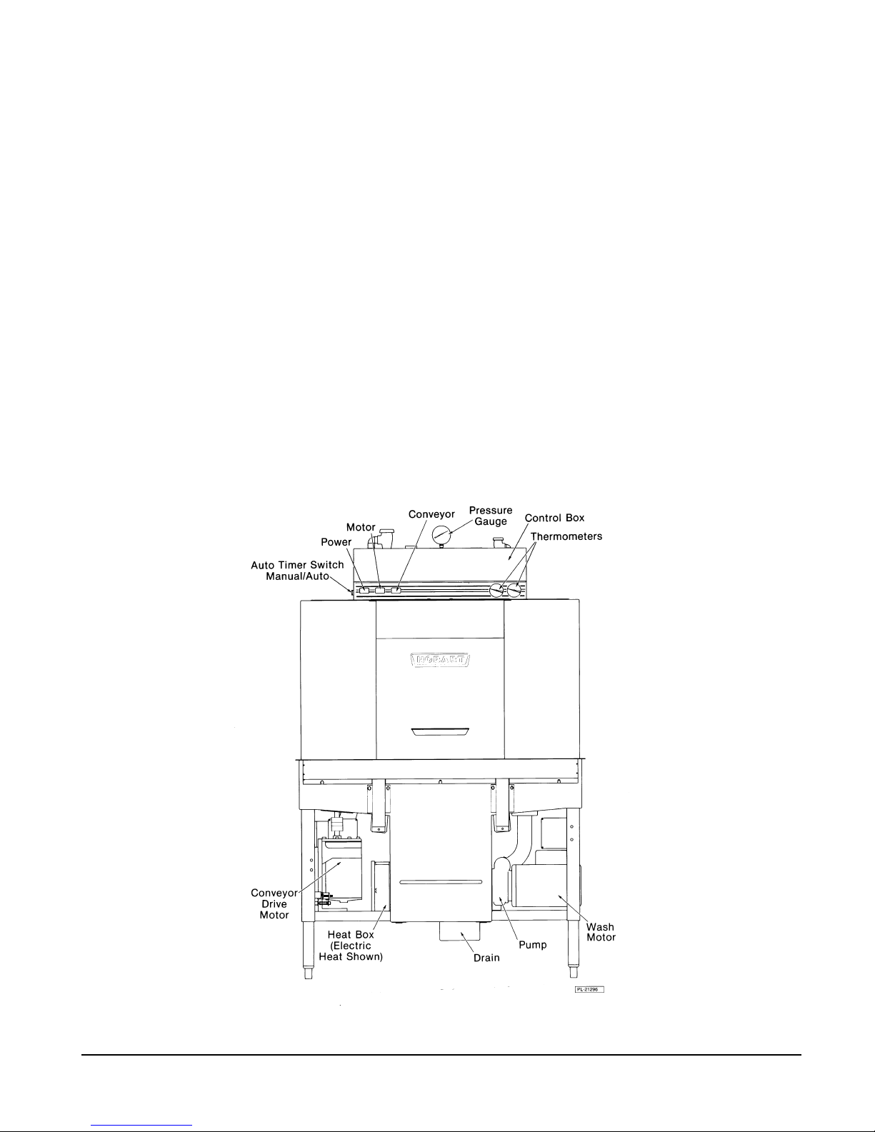
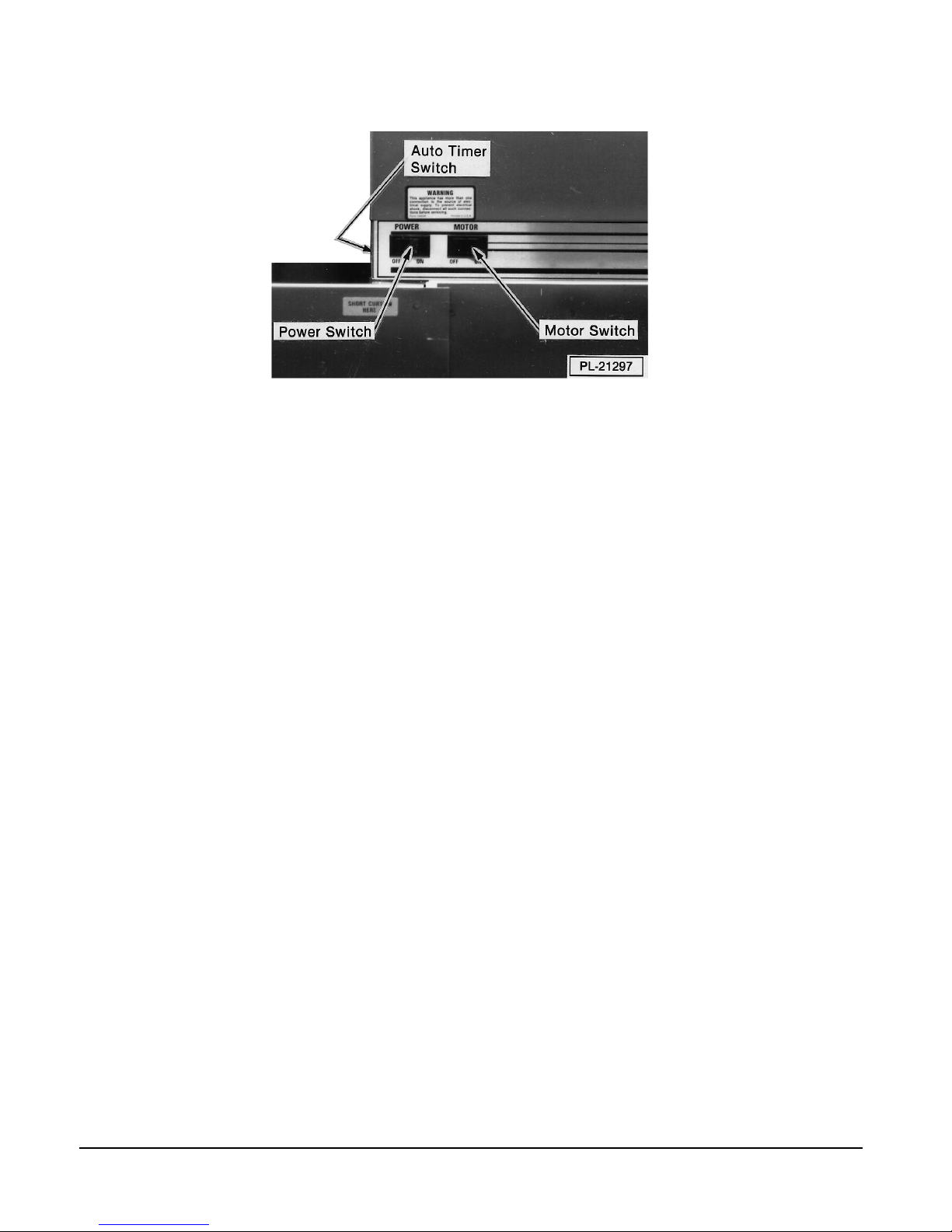
Controls (Fig. 1)
Fig. 1
The controls are mounted on top of the chamber. There are three operational control switches housed in
the control box: Power (On-Off); Motor (On-Off); and Timer (Manual-Auto). A pilot circuit transformer
provides a reduced voltage of 115 volts for the machine controls. When equipped for gas heat, a step-down
transformer provides a reduced voltage of 24 volts for the igniter board(s) and valves.
Motor and Pump Units
The wash / rinse pump and motor are centrifugal-type cast stainless steel with stainless steel impeller. The
2 HP motor is available in the following voltages:
Volts Hz Phase Volts Hz Phase
208-240 60 1 200-240 50 3
208-240 60 3 380-415 50 3
200-240 50 1 380 60 3
480 60 3
600 60 3
1
The conveyor drive motor is a
⁄6 HP gear motor with the same voltage as the wash / rinse pump motor.
A 1 HP prewash pump motor is standard on CRS, CCS, and CPW models. A 2 HP prewash pump motor
is optionally available on the CPW models only. Voltage and construction are the same as the wash / rinse
pump motor.
All motors have built-in thermal overload protection with manual reset.
Vacuum Breakers
The final rinse and fill lines contain atmospheric vacuum breakers that prevent any reverse flow of water
from the dishwasher into the potable water supply.
Heater Protection
A float-activated switch located in the wash tank (and rinse tank if included) automatically turns off the heat
supply if the water level is too low. Once the water returns to the proper level, the heating circuit becomes
operational if heat is demanded.
An overtemperature protector is also provided for electric and gas heat. If overheating should occur, the
heat supply will be turned off. Turn the Power switch Off and contact your local Hobart service office.
– 5 –
Page 6

Thermometers
Dial thermometers for wash and final rinse are indicated in
°
F and °C on the faceplate.
Door Interlocks
Door interlock switches will prevent machine operation while an inspection door is open. If a door is opened
while the machine is operating, the pumps and conveyor will automatically turn off. After the door is closed,
the machine must be restarted by pushing the Motor switch On.
Wash and Rinse Arms
Upper and lower prewash, wash, and final rinse arms are removable. All machines have metal final rinse
arms. A CPVC final rinse piping system is available for those machines offering low temperature operation
(if so ordered).
RS Unit and CS Unit
CCS86A, CCS110A, CCS86W, CCS110W)
(CRS66A, CRS66AW, CRS76A, CRS86A, CRS110A , CRS86W, CRS110W, CCS66A, CCS66AW, CCS76A,
The 22" Recirculating Scrapper is a power prewash unit which uses overflow water, hence, no fill valve is
required.
PW Unit
(CPW80A, CPW80AW, CPW90A, CPW100A, CPW124A, CPW100W, CPW124W)
The 36" Prewash unit is a large power prewash unit which uses overflow water, hence, no fill valve is
required.
Dual Rinse Unit
(C64W, CRS86W, CCS86W, CPW100W, C88W, CRS110W, CCS110W, CPW124W)
The 36" Dual Rinse Unit provides a dedicated final rinse in combination with a pumped auxiliary rinse. The
dual rinse section is only available on two-tank C64A or C88A parent units.
Auto Fill
Close door(s) and push the Power switch On. After a 5-second delay, the machine fills automatically.
Auto Timer
The Auto Timer switch is located on the left side of the control box. Designed to save electrical power, it
is adjusted to shut off pump and drive motors a set amount of time after the last rack exits the dishwasher.
To restart, slide a rack into the machine or push the Motor switch On. To change the time setting, contact
your local Hobart-authorized service office.
Common Drain
A stainless steel common drain tube connects the dishwasher and prewash drains together, thus requiring
only one drain connection at installation. A unit with a dual rinse section is also plumbed for a common drain.
Front Panel
Stainless steel front panel conceals pumps and plumbing.
Common Water Connection
A single water connection for Fill and Final Rinse is standard. This requires a minimum incoming water
temperature of 180°F for high-temperature machines (140°F for low-temperature machines).
– 6 –
Page 7

OPTIONAL EQUIPMENT
Blower Dryer — Dishes are dried by forced heated air (3-phase machines only).
Electric Booster Water Heater — Supplies minimum 180°F water for fill and final rinse if Separate Water
Connection option is not included, or for final rinse only if Separate Water Connection option is included.
Conveyor Dwell — The optional conveyor dwell switch (Conveyor On-Off) is housed in the control box.
Condenser — Removes excess moisture from exhaust air before returning air to dishroom.
Single-Point Electrical Connection — Option for electric heat machines. Requires one electrical service
connection. Available for 3-phase machines only.
Half-Rack Unit — The special cradle unit can accommodate standard 20"
than standard racks, 10" x 20", 14"
x 20" and 16" x 20".
x 20" racks, as well as shorter
Extended Hood — Provides a dampered vent and acts as an effective splash shield for the discharge end
of the wash chamber. The exhaust requirement at the entrance end is 200
end, the exhaust requirement is 400
CFM maximum.
CFM maximum; at the discharge
Side Loader — Allows machine to be placed in a corner or used where area at the load end is limited.
Available with or without hood.
Vent Hood — (Sides are not as long as the extended hood.) A dampered exhaust opening controls steam
and water splash to work area. The exhaust requirement at the entrance end is 200
discharge end, the exhaust requirement is 400
CFM maximum.
CFM maximum; at the
Vent Fan Control — Switches customer’s vent fan on when power switch is on.
Table Limit Switch — Shuts the machine off when the unloading table is full of racks.
CS / RS-22 Lower Prewash Arm — Optional on the CRS and CCS models.
DDU38 Unloader — Moves racks in a 90 degree arc from the unload end of the dishwasher to a dish table;
this allows the machine to be placed in a corner or to be used where area at the unload end is limited.
Separate Water Connection — Individual Fill (140°F) and Final Rinse (min. 180°F) water connections
are available on high-temperature machines only.
Hobart Infrared Booster Gas Water Heater — Supplies minimum 180°F water for fill and final rinse if
Separate Water Connection option is not included, or for final rinse only if Separate Water Connection option
is included.
– 7 –
Page 8
INSTALLATION
UNPACKING
Immediately after unpacking the dishwasher, check it for possible shipping damage. If this machine is
found to be damaged, save the packaging material and contact the carrier within 15 days of delivery.
Prior to installation, verify that the electrical service agrees with the specifications on the machine data
plate, which is located on the right-hand side of the control box.
The electrical diagram is located on the inner surface of the control box cover.
After unpacking the dishwasher, remove the items shipped uninstalled (overflow tube, pump intake
strainer, curtains, and chamber hole plug kit) and instructions from inside the dishwasher. Set the
dishwasher in its proper location. Adjust the height and level by turning the adjustable feet. NOTE: The
dishwasher must be positioned and leveled before making plumbing connections. Remove shipping block
from the drive motor.
INSTALLATION CODES
Installation must be in accordance with state and local codes, or in the absence of local codes, with
the National Fuel Gas Code, ANSI Z223.1 (latest edition) if applicable, and the National Electrical Code
ANSI/NFPA 70 (latest edition). In Canada, the installation standards are: CAN/CGA B149.1,
CAN/CGA B149.2, and CSA C22.2 No.1 (latest editions).
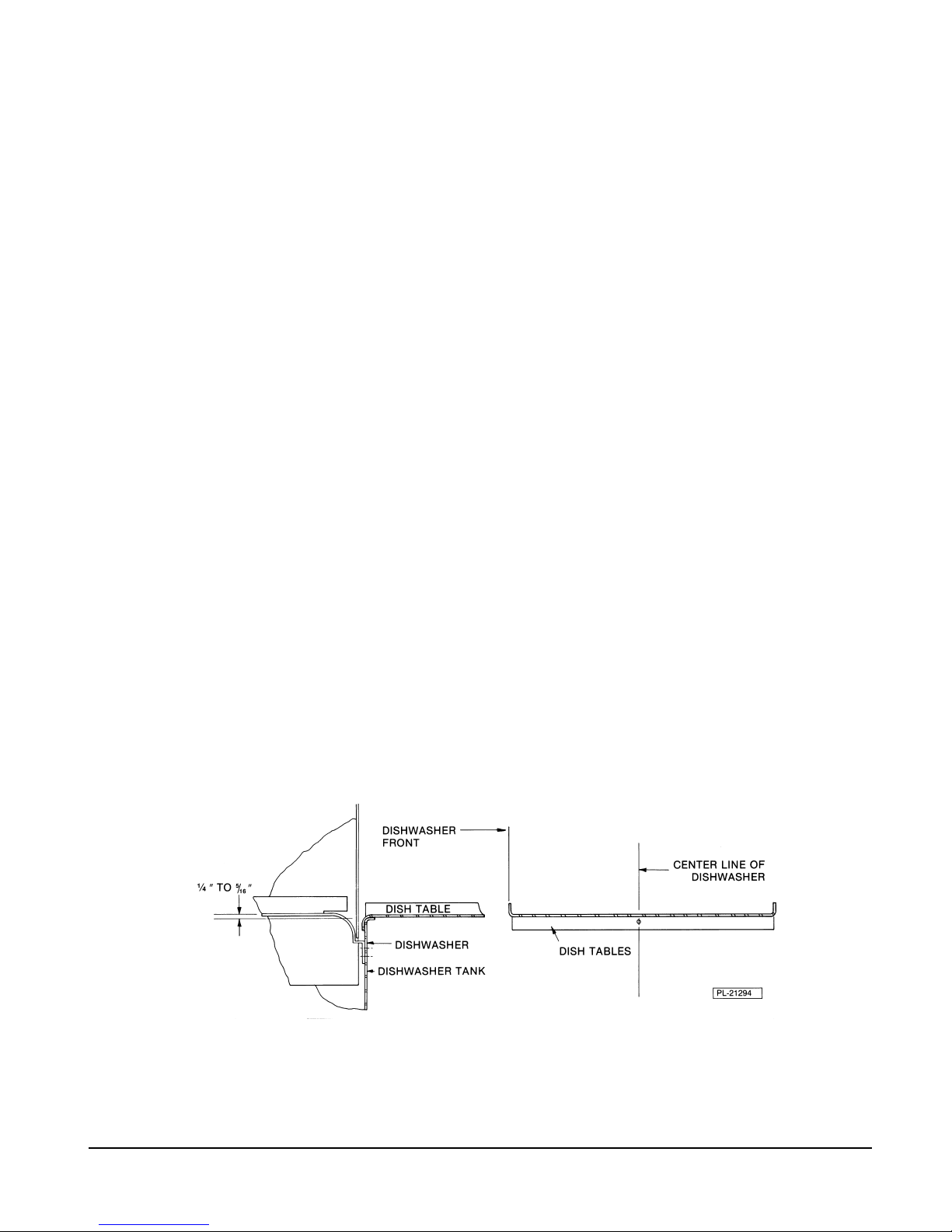
ASSEMBLY
Dish tables should be fitted into the dishwasher (Fig. 2). Use Mastic between table and lip of tank to prevent
1
leakage. Rack track height should be from
⁄4" to 5⁄16" (Fig. 2) above the tank lip. Dish tables should be sloped
so that any water carried from the dishwasher will drain back into it.
Fig. 2
– 8 –
Page 9

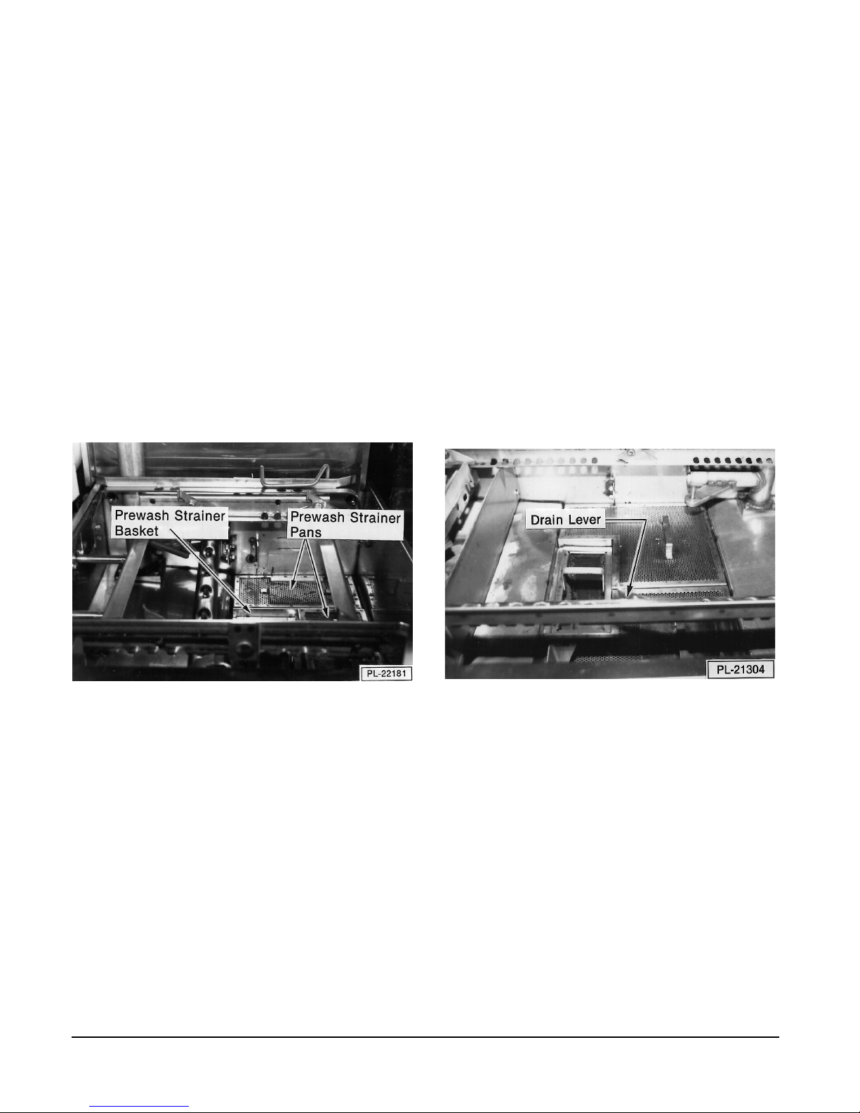
Remove the strainer basket and strainer pans from the wash chamber (Fig. 3).
Place the pump intake strainer on the three hooks as shown in Fig. 4.
Place the overflow tube in the retainer (Fig. 5).
Model C-44A Shown
Fig. 3 Fig. 4 Fig. 5
Assemble Dual Rinse Unit to Parent Machine (Models C64W, CRS86W, CCS86W, CPW100W, C88W, CRS110W,
CCS110W, CPW124W)
Shipping length limitations require that the Dual Rinse Unit be shipped separately on longer three-tank
machines. Assemble as follows:
Remove Front Panels and Wireway Covers from both parent machine and Dual Rinse unit.
Remove Track bolts and nuts at the connecting end of both Parent machine and Dual Rinse unit. Save
the longer bolts (and washers and nuts) for reconnection of tracks after Parent machine and Dual
Rinse units are bolted together.
1
Apply 1
/2" Foam Tape to both sides and top of wash chamber on Parent machine where 15 bolt holes
are located. Apply 6" Foam Tape to tank on Parent machine (Fig. 6).
Position both Parent machine and Dual
Rinse unit together. Use a spirit level and
adjust feet on both units so 15 holes line up.
Punch through tape on all 15 bolt holes (top
Parent Machine
Dual Rinse
and sides) using a screwdriver or punch.
Bolt together with 15 screws (
1
lockwashers, and nuts (Inset A).
/4-20 x 5/8"),
1-1/2" Foam Tape
6" Foam Tape
1-1/2" Foam Tape
Permagum
INSET A
Assemble Tank Support under lip edge of
parent machine inside tank of Dual Rinse
5
unit using 5 screws (
washers, lockwashers, and nuts (Inset B).
/16 -18x5/8") with
Tank Support
Seal bolt locations with Permagum.
Reconnect Tracks in both Parent machine
and Dual Rinse unit through common holes
using longer bolts, lockwashers and nuts,
that were previously removed.
Parent Tank
6" Foam Tape
Permagum
Dual Rinse Tank
INSET B
PL-52470
Fig. 6
– 9 –
Page 10

Connect the Drain from Dual Rinse unit to the Union on the
Drain pipe underneath the Parent machine.
Connect Common Fill to water supply on top of machine at
the Union. NOTE: If Separate Fill is ordered for the Dual
Rinse unit, connect the Dual Rinse Fill / Final Rinse to
180°F minimum water supply.
Insert the Final Rinse Flow Back extension pipe into the
larger pipe on the Parent machine. Tube goes through
both tanks, into larger pipe on Parent machine; flange and
cork gasket on each side are connected with two screws
5
/16 -18 x 1") with lockwashers, nuts, and Permagum
(
(Fig. 7). Tanks should not leak.
Connect the overflow from the tank on the Dual Rinse unit to the
Flow Back pipe on the Parent machine. Connect the flange of the
Flow Back Weldment -Inside (Inlet) to the Flow Back Weldment
-Outside (Pipe) with cork gasket through the tank wall.
Position Pipe through Parent machine tank wall
(pre-assemble flange and gasket); place Ring Seal and
second flange and gasket; complete assembly with 4 bolts,
washers, lockwashers, and nuts at each location (Fig. 8).
Connect Cradle in Parent machine to
Cradle in Dual Rinse unit with the two
Connecting Rods and 4 each (2 large
washers, 1 small washer, 1 lockwasher
and 1 nut) (Fig. 9).
Ring Seal
Flange
Flange
Parent Tank Dual Rinse Tank
Flange Flange
Permagum
Cork Gasket Cork Gasket
Fig. 7
Auxiliary Rinse
Overflow (Inlet)
Flange
Flange
Cork Gaskets
Tank Wall
Auxiliary Rinse
Pipe
PL-51500
Connect the mating wiring harness
connectors inside the front wireway.
Reinstall wireway covers and front panels.
Connecting Rod
Fig. 9
Cork Gaskets
Tank Wall - Parent
PL-51501
Fig. 8
Cradle
PL-51502
– 10 –
Page 11
VENTING MOIST AIR FROM THE VENT HOOD CONNECTIONS
Moist air escapes from each end of the conveyor type dishwasher. The exhaust requirements
recommended are a maximum of 200 CFM at the entrance end of the dishwasher and a maximum of
400 CFM at the discharge end. Optional vent hoods or extended hoods may be provided at each end
of the machine. Sufficient make-up air must be provided so the exhaust flow results in a positive
building pressure in the room in which the unit is located (more outside air than exhaust air). Hoods
are provided with 4" x 16" vent connectors with Vent Dampers which allow adjustment during
installation. Typical construction is for 'pant-leg' hood connections to the 4" x 16" vent connectors
(Fig. 10). Vent stacks must be water tight and fit inside the vent connector openings.
Alternately, a vent hood can be installed over the entire machine (see Fig. 12). Low temperature
machines contribute a lower amount of moisture into the air and probably require no additional venting.
On high temperature machines, the accumulation of moisture on interior walls and ceilings is to be
avoided by use of proper venting. The typical requirement for a high temperature machine will be for
a Type II hood because the dishwashing machine makes little if any grease laden vapors and mostly
contributes moist air. A Type I hood will also meet most requirements. The local code will determine
what is required for each site.
Venting requirements for flue gas for gas heat machines is covered separately on pages 14 thru 16.
'Pant Leg' Duct
4" x 16" Vent Connector
Extended Hood
C-Line Dishwasher
Fig. 10
– 11 –
Page 12

WATER REQUIREMENTS
Proper water quality can improve ware washing performance by reducing spotting, lowering chemical
supply costs, enhancing effectiveness of labor, and extending equipment life. Local water conditions
vary from one location to another. The recommended proper water treatment for effective and efficient
use of this equipment will also vary depending on the local water conditions. Ask your municipal water
supplier for details about local water specifics prior to installation.
Recommended water hardness is 4 – 6 grains of hardness per gallon. Chlorides must not exceed 50
parts per million. Water hardness above 6 grains per gallon should be treated by a water conditioner
(water softener or in-line treatment). Water hardness below 4 grains per gallon also requires a water
treatment to reduce potential corrosion. Water treatment has been shown to reduce costs associated
with machine cleaning, reduce deliming of the dishwasher, reduce detergent usage, and reduce
corrosion of metallic surfaces in the booster water heater and dishwasher.
Sediment, silica, chlorides, or other dissolved solids may lead to a recommendation for particulate
filtration or reverse osmosis treatment.
If an inspection of the dishwasher or booster heater reveals lime build-up after the equipment has been
in service, in-line water treatment should be considered, and, if recommended, should be installed and
used as directed. Contact your Hobart Service office for specific recommendations.
PLUMBING CONNECTIONS
WARNING: PLUMBING CONNECTIONS MUST COMPLY WITH APPLICABLE SANITARY, SAFETY,
AND PLUMBING CODES.
The plumber who connects this machine is responsible for making certain that both water and steam lines
are THOROUGHLY FLUSHED OUT BEFORE connecting to any manual valve or solenoid valve.
This ‘‘flush-out’’ is necessary to remove all foreign matter, such as chips (resulting from cutting or
threading of pipes), pipe joint compound from the lines, or, if soldered fittings are used, bits of solder or
cuttings from the tubing. Debris, if not removed, may lodge in the valves and render them inoperative.
Manual valves or solenoid valves fouled by foreign matter, and any expenses resulting from this fouling,
are NOT the responsibility of the manufacturer.
DRAIN CONNECTION(S)
Connect the drain through a trap to the sewer using 2" pipe. The tank(s)' common drain requires only one
connection to the floor drain.
If a grease trap is required by code, it should have a minimum flow capacity of 31 gallons per minute.
On single tank (C44A/AW & C54A family units) the final rinse drain-off pan outlet is to be connected to the
building drain system (and not to the machine drain casting).
– 12 –
Page 13

FILL / FINAL RINSE CONNECTION (Fig.11)
Fig. 11
Water must be proper hardness. Recommended hardness range is 4 – 6 grains / gallon. Lower hardness
can promote corrosion, higher hardness may cause excessive formation of lime scale.
3
Use
⁄4" pipe for the connecting line. A flowing pressure of 15 to 25 psig and a minimum temperature of
180°F must be maintained at the machine for common water connection. For long runs, use larger pipe and
insulation to ensure adequate pressure and temperature. If flow pressure exceeds 25 psig, a pressurereducing valve (not furnished) must be installed in the supply line. CAUTION: The water pressure
regulator must have a relief by-pass. Failure to use the proper type of pressure regulator may
result in damage to the unit.
A pressure gauge is provided for verification of proper water pressure. The pressure gauge is connected
into a shutoff cock which MUST ALWAYS REMAIN CLOSED except when making an instantaneous
check of line pressure.
STEAM CONNECTION (when equipped)
CAUTION: Steam supply pressure must agree with steam trap selection. The steam trap (supplied)
will be for either 0-20 psig (flowing) or 21-50 psig (flowing).
The steam supply must be between 10 and 50 psig flowing pressure. If flowing pressure exceeds 50 psig,
a pressure regulator (not supplied) must be installed in the supply line.
3
If flowing pressure is 10 psig, use 1" piping; if over 10 psig, use
⁄4" piping. Steam flow is controlled by
solenoid valves.
If machine is equipped with steam injector(s), one supply connection is required. For single-tank steam
coil installations, two connections per coil are required, one for supply and one for return. For two-tank
steam coil installations, one common supply connection and two return connections (one per tank) are
required.
– 13 –
Page 14

GAS CONNECTION (when equipped)
Check the gas data plate attached to the dishwasher or tag attached to the gas burner tubing for type of
gas to be used.
The burner is not adjustable. If flowing gas pressure is above 7" W.C. (natural gas) or 11" W.C. (propane
gas), an additional regulator valve (not supplied) must be installed in the supply line. Static incoming line
pressure should not exceed 14.0" W.C. for either propane or natural gas.
• IMPORTANT: Make sure the installation meets the local code for your area.
SNOITACIFICEPSSAG
GNIWOLFGNIWOLF
sledoMsaGfoepyTrH/UTB
A45C&A44C
seilimaF
A46C
ylimaF
A88C
ylimaF
larutaN000,25TPN"2/1.C.W"5.3.C.W"7.C.W"2.3
enaporP000,05TPN"2/1.C.W"0.9.C.W"11.C.W"0.9
larutaN000,49TPN"4/3.C.W"5.3.C.W"7.C.W"2.3
enaporP000,49TPN"4/3.C.W"0.9.C.W"11.C.W"4.8
larutaN000,401TPN"4/3.C.W"5.3.C.W"7.C.W"2.3
enaporP000,001TPN"4/3.C.W"0.9.C.W"11.C.W"0.9
GNIWOLFGNIWOLF
GNIWOLF
)nmuloCretaW(.C.WsehcnI)nmuloCretaW(.C.WsehcnI
)nmuloCretaW(.C.WsehcnI)nmuloCretaW(.C.WsehcnI
eniLgnimocnI
eziS
muminiMmuminiM
muminiMmuminiMmumixaMmumixaM
muminiM
erusserPeniLgnimocnIerusserPeniLgnimocnI
erusserPeniLgnimocnIerusserPeniLgnimocnI
erusserPeniLgnimocnI
mumixaMmumixaM
mumixaM
)nmuloCretaW(.C.WsehcnI
CITATSTON–ERUSSERPSAGCITATSTON–ERUSSERPSAG
CITATSTON–ERUSSERPSAGCITATSTON–ERUSSERPSAG
CITATSTON–ERUSSERPSAG
dlofinaMdlofinaM
dlofinaMdlofinaM
dlofinaM
erusserPerusserP
erusserPerusserP
erusserP
NOTE: DO NOT use Teflon tape on gas line pipe threads. For gas line pipe connections, use Loctite 565,
Hobart part 546292, or a flexible sealant suitable for use with Natural and Propane Gases.
The appliance and its gas connections must be leak tested before placing the appliance in operation.
Use soapy water for leak test. DO NOT use open flame. The installation must conform with local codes,
or in the absence of local codes, with the National Fuel Gas Code, ANSI Z223.1 (latest edition). Copies
may be obtained from the American Gas Association, Inc., 1515 Wilson Blvd., Arlington, VA 22209.
The appliance and its individual shutoff valve must be disconnected from the gas supply piping system
during any pressure testing of that system at test pressures in excess of
1
/2 psig (3.45 kPa).
The appliance must be isolated from the gas supply piping system by closing its individual manual
shutoff valve during any pressure testing of the gas supply piping system at test pressures equal to or
less than
1
/2 psig (3.45 kPa).
Dissipate test pressure from the gas supply line before re-connecting the appliance and its manual
shutoff valve to the gas supply line. Caution: Failure to follow this procedure may damage the gas
valve.
The dishwasher must be installed so that the flow of combustion and ventilation air will not be
obstructed. Adequate clearances for air openings into the combustion chamber must be provided.
Make sure there is an adequate supply of make-up air in the room to allow for combustion of the gas
at the burner(s).
Keep the appliance area free and clear from all combustible substances. Do not obstruct the flow of
combustion and ventilation air. The dishwasher must have a minimum clearance from combustible
construction of 3 inches at the rear and 0 inches at the sides. A clearance of 40 inches must be provided
at the front of the dishwasher for servicing and proper operation.
The burner is ignited automatically by solid state electronic circuitry; there is no pilot light. Gas flow is
regulated by the temperature control circuit.
– 14 –
Page 15
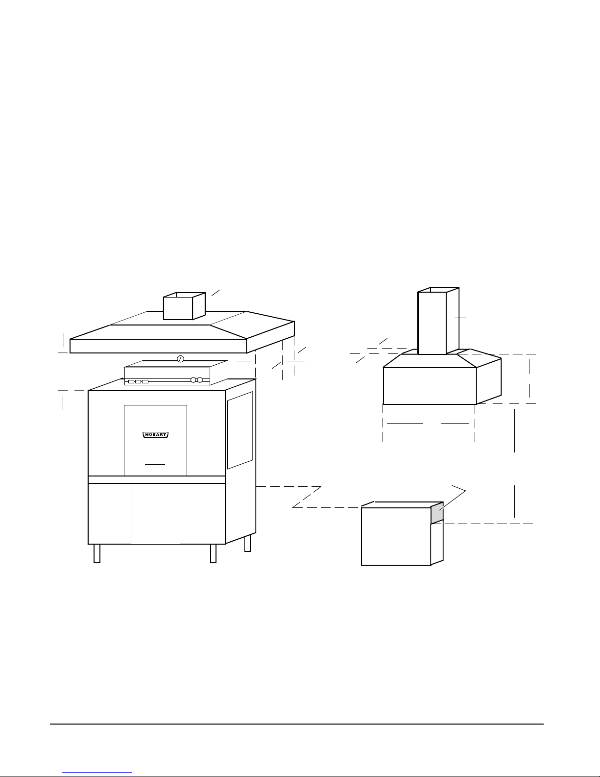
VENTING REQUIREMENTS FOR C-LINE MACHINES WITH GAS HEAT
The Hobart C-Line dishwasher equipped for gas tank heat is not provided with a flue collar and is not
intended to have the flue directly connected to a ventilation system. However, the products of
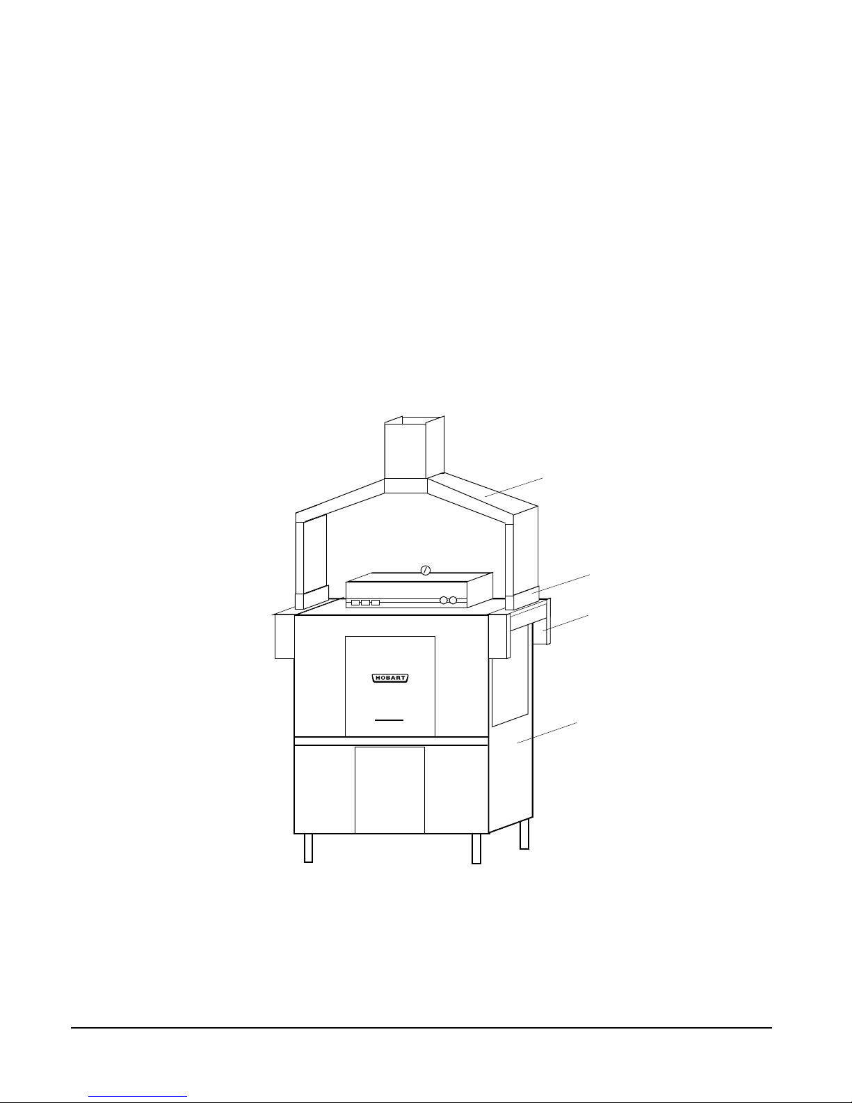
combustion must be vented to the outside air. A vent hood over the entire dishwasher (Fig. 12) can
be employed to vent both the moist air from the dishwashing chamber and the flue gases from the gas
heater. The volume of flue exhaust required for venting moist air and flue gases using a single vent
hood over the entire dishwasher must be calculated using the formula in the
Hood Specifications Table
on the next page. If using the 'Pant Leg' duct (Fig. 10), a small vent hood (Fig. 13) positioned about
18 inches above the flue exit at the rear of the dishwasher and connected to existing ductwork may be
used for the flue gases. The volume of flue exhaust is less than 100 CFM and the mini vent hood should
not exceed that amount.
In either case, if a powered means of exhaust is used, an electrical interlock must be provided to allow
the flow of gas to the dishwasher burner only when the exhaust system is in operation.
For additional information, refer to the National Fuel Gas Code, ANSI Z223.1, NFPA 54.
In all cases, local codes will prevail.
➤
➤
1' TO 4'
CLEARANCE
➤
EXHAUST DUCT SHOULD
BE CENTERED IN HOOD
➤
➤
➤
➤
6"
MINIMUM
OVERHANG
ON ALL SIDES
18" MINIMUM
OVERHANG
RECOMMENDED
AT LOAD
AND UNLOAD
OPENINGS
MINI VENT HOOD
31/2"
➤
➤
➤
DISHWASHER FLUE EXIT
6"
➤
3" x 3" DUCT INTO
CURRENT SYSTEM
➤
➤
➤
4"
➤
➤
18" GAP
MINIMUM
➤
Fig. 12 Fig. 13
Type I or Type II canopy hoods are recommended. A factory built commercial exhaust hood may be
listed as conforming to Underwriters Laboratory's standard 710 titled
Cooking Equipment
. Hoods must be installed according to the manufacturer's instructions. Make-up
air must be provided so that the exhaust flow rate results in a positive building pressure in the room
where the unit is located (more outside air than exhaust air). Factory built hoods not tested to UL
standard 710 and custom built hoods must comply with the following specifications: Stainless steel
0.037 inch (0.94
square foot (7
mm) [No.20 Gage] minimum thickness or copper sheet weighing at least 24 ounces per
2
Kg/m
); the hood must be secured in place by non-combustible supports and must meet
the RATE OF EXHAUST FLOW CALCULATIONS on the next page.
Exhaust Hoods for Commercial
– 15 –
Page 16

RATE OF EXHAUST FLOW CALCULATIONS
Based on the 1996 International Mechanical Code.
➤
➤
CLEARANCE
HEIGHT
➤
The Rate of air flow required for a vent hood is
calculated using the following definitions:
Q = Rate of Air Flow in Cubic Feet Per Minute
or [ CFM ] Required for the Hood.
A = Area of Hood Opening = (L x W) in Feet
2
D = Clearance Height = Distance in Feet from
lower lip of hood to top of dishwasher
chamber.
P = Perimeter of Hood that is Open. This
depends on the hood design, as follows:
ngiseDdooH evoclArenroCllaWdnalsI
sediSnepOforebmuN nepOediS1nepOsediS2nepOsediS3nepOsediS4
=P LW+LW+W+LW+W+L+L
snoisnemiD teeFteeFteeFteeF
LENGTH
alumroFnoitaluclaCretemireP
➤
WIDTH
➤
➤
If there are four open sides (Island Design), the calculation of the Rate is as follows:
Q = 75 x A
If there are three or fewer open sides, the calculation of the Rate is as follows:
Q = 50 x A
As an alternate method, the Rate can be calculated as follows:
Q = 50 x P x D
Example:
L = 6 W = 3 D = 2
ngiseDdooH evoclArenroCllaWdnalsI
sediSnepOforebmuN nepOediS1nepOsediS2nepOsediS3nepOsediS4
Ax57=Q MFC0531
Ax05=Q MFC009MFC009MFC009
DxPx05=Q MFC006MFC009MFC0021MFC0081
snoitaluclaCetaR
– 16 –
Page 17
ELECTRICAL CONNECTIONS — DISHWASHER
WARNING: ELECTRICAL AND GROUNDING CONNECTIONS MUST COMPLY WITH THE APPLICABLE
PORTIONS OF THE NATIONAL ELECTRICAL CODE ANSI / NFPA 70 (LATEST EDITION) AND/OR
OTHER LOCAL ELECTRICAL CODES.
WARNING: DISCONNECT ELECTRICAL POWER SUPPLY AND PLACE A TAG AT THE DISCONNECT
SWITCH TO INDICATE THAT YOU ARE WORKING ON THE CIRCUIT.
Some machines may have more than one electrical power supply. Separate electrical power connection
is required for the Dual Rinse unit (if so equipped). All supplies MUST be disconnected.
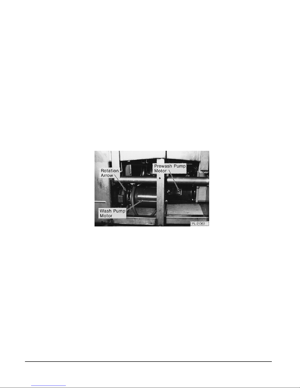
Motor(s)
Connect a permanent electrical power supply to the terminal block in the control box. Three-phase
motor(s) must rotate the impeller in the direction of the arrow found on the pump housing of the motor pump
unit (Fig. 14), and the drive motor must rotate clockwise when viewed from the output shaft end. Before
placing the machine into service, a check must be made to verify correct rotation. Only one motor needs
to be checked as the machine is wired at the time of manufacture so that all motors will rotate the same
direction.
Fig. 14
If the impeller does not rotate in the direction of the arrow, DISCONNECT POWER SUPPLY(IES) to the
machine and interchange any two power supply leads at the control box terminal block. On machines with
a circuit breaker box, reverse any two leads at the incoming power supply block in the circuit breaker box
(three-phase only). Start the machine momentarily and verify proper direction of rotation.
Electric Heat
Connect a permanent electrical power supply to the line terminals of the control box. The tank water
temperature is regulated by a solid state thermostat which is preset at the factory and should not require
adjustment. If an adjustment is necessary, contact your local Hobart-authorized service office. Use the
machine thermometers for verification of proper water temperatures.
– 17 –
Page 18

ELECTRICAL CONNECTIONS — OPTIONAL EQUIPMENT
WARNING: ELECTRICAL AND GROUNDING CONNECTIONS MUST COMPLY WITH THE
APPLICABLE PORTIONS OF THE NATIONAL ELECTRICAL CODE AND/OR OTHER LOCAL
ELECTRICAL CODES.
WARNING: DISCONNECT ELECTRICAL POWER SUPPLY AND PLACE A TAG AT THE DISCONNECT
SWITCH TO INDICATE THAT YOU ARE WORKING ON THE CIRCUIT.
Electric Booster Water Heater — Power Supply Connection
NOTE: Electric Booster electrical connection must be separate from the dishwasher electrical
connection.
Before making electrical connection, test the electrical
service to assure that it agrees with the specifications
on the Electric Booster data plate (Fig. 15). Also,
refer to the wiring diagram attached inside the cover
of the Electric Booster.
A fused disconnect switch or circuit breaker (not
supplied) must be installed in the electrical service
line supplying this booster and should meet the
requirements of your local electrical code.
Booster electrical connection is made to the service
connection terminal block in the booster. If grounding
is not provided by the conduit used, connect the
ground lead to the grounding lug provided (Fig. 14).
Fig. 15
OPTIONAL EQUIPMENT CONTROL CONNECTIONS
Detergent Dispenser
Maximum rating for detergent dispenser connected to DPS1 and DPS2 is 1.5 Amps at line voltage.
Rinse Aid Dispenser
Maximum rating for rinse aid dispenser connected to RPS1 and RPS2 is 1.5 Amps at line voltage.
Vent Fan Control
Maximum rating for vent fan control connected to VFC1 and VFC2 is either 16 Amps at 240 Volts or
8 Amps at 480 - 600 Volts.
Hobart Infrared Booster Gas Water Heater
The maximum rating for connecting a Hobart infrared gas booster water heater to BSTR1 and BSTR2
is 0.15 Amp at 120 Volts.
– 18 –
Page 19
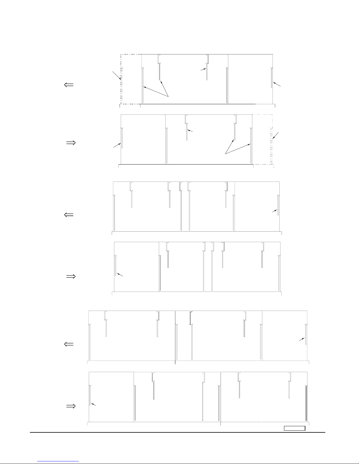
CURTAIN INSTALLATION
SINGLE TANK MACHINES (C44A/AW AND C54A SERIES)
FINAL RINSE
C54A SERIES
SECTION(ADD
STANDARD
CURTAIN)
RIGHT TO LEFT
C44A/AW
SERIES
C44A SERIES (GAS HEAT)
FINAL
OR C44AW & C54A SERIES
RINSE
WASH
ALL HEATS.
C44A/AW SERIES
SHOWN. REVERSE
FOR C54A SERIES.
PREWASH
(WHERE APPLICABLE)
SHORT CURTAIN (CRS)
STANDARD CURTAIN (CPW)
SHORT CURTAIN (CCS)
(LOCATE AT ENTRANCE)
PREWASH
(WHERE APPLICABLE)
LEFT TO RIGHT
SHORT CURTAIN (CRS)
STANDARD CURTAIN (CPW)
SHORT CURTAIN (CCS)
(LOCATE AT ENTRANCE)
TWO TANK MACHINES (C64A SERIES)
RIGHT TO LEFT
LEFT TO RIGHT
FINAL
RINSE
PREWASH
(WHERE APPLICABLE)
SHORT CURTAIN (CRS)
STANDARD CURTAIN (CPW)
SHORT CURTAIN (CCS)
(LOCATE AT ENTRANCE)
RINSE
TWO TANK MACHINES (C88A SERIES)
RINSE
FINAL
RINSE
RIGHT TO LEFT
WASH
C44A SERIES (GAS HEAT)
OR C44AW & C54A SERIES
ALL HEATS.
C44A/AW SERIES
SHOWN. REVERSE
FOR C54A SERIES.
C44A/AW
SERIES
FINAL
RINSE
**
WASH
PREWASH
(WHERE APPLICABLE)
SHORT CURTAIN (CRS)
STANDARD CURTAIN (CPW)
SHORT CURTAIN (CCS)
(LOCATE AT ENTRANCE)
**
WASH
RINSE
FINAL
RINSE
* 6 inches Higher Than Standard Models Only.
WASH
(WHERE APPLICABLE)
SHORT CURTAIN (CRS)
STANDARD CURTAIN (CPW)
SHORT CURTAIN (CCS)
(LOCATE AT ENTRANCE)
FINAL RINSE
C54A SERIES
SECTION (ADD
STANDARD
CURTAIN)
PREWASH
PREWASH
(WHERE APPLICABLE)
LEFT TO RIGHT
SHORT CURTAIN (CRS)
STANDARD CURTAIN (CPW)
SHORT CURTAIN (CCS)
(LOCATE AT ENTRANCE)
– 19 –
RINSEWASH
FINAL
RINSE
PL-51508
Page 20
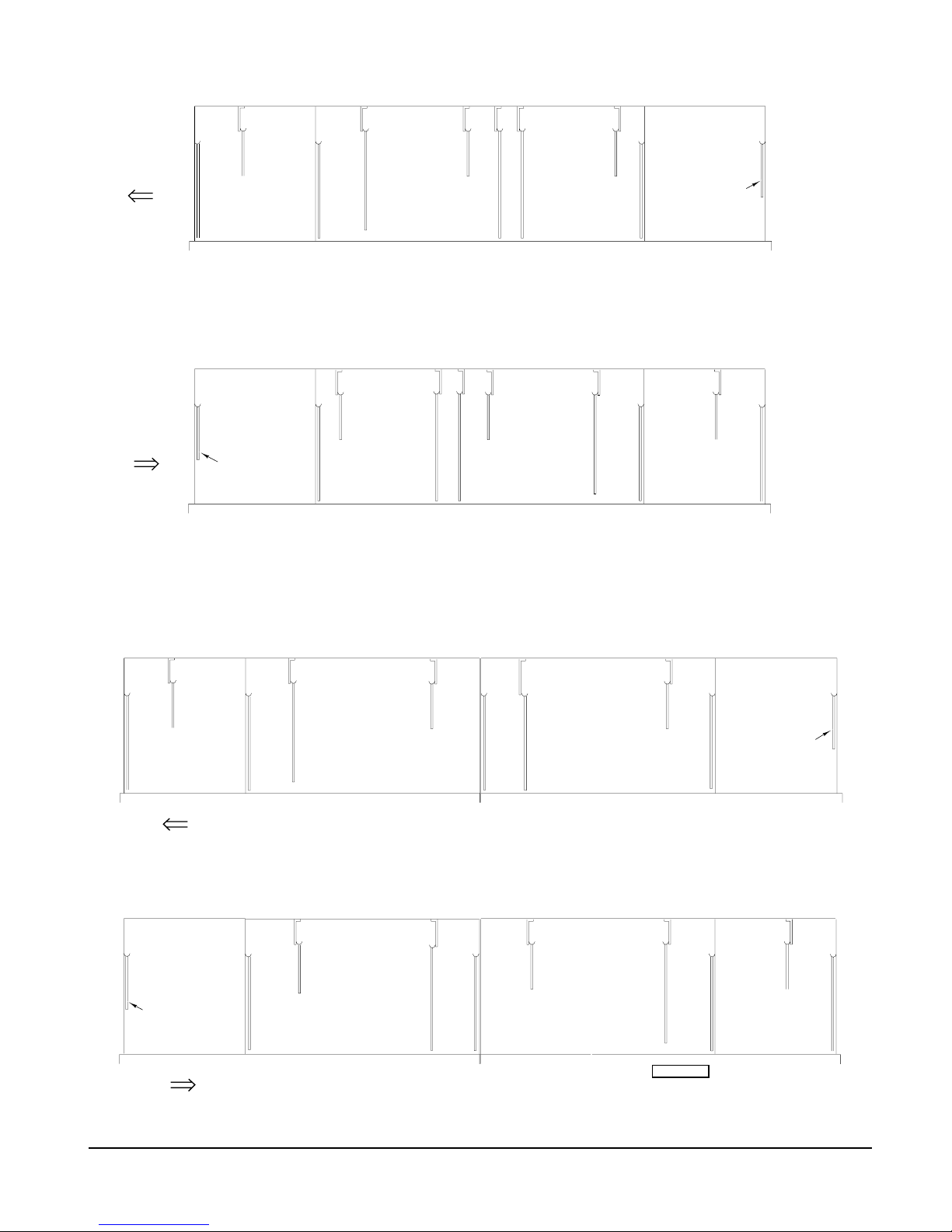
TWO TANK MACHINES (C64W SERIES)
**
RIGHT TO LEFT
LEFT TO RIGHT
FINAL
RINSE
(WHERE APPLICABLE)
SHORT CURTAIN (CRS)
STANDARD CURTAIN (CPW)
SHORT CURTAIN (CCS)
(LOCATE AT ENTRANCE)
AUX
RINSE
PREWASH
RINSE
WASH
**
WASH
RINSE
* 6 inches Higher Than Standard Models Only.
PREWASH
(WHERE APPLICABLE)
SHORT CURTAIN (CRS)
STANDARD CURTAIN (CPW)
SHORT CURTAIN (CCS)
(LOCATE AT ENTRANCE)
AUX
RINSE
FINAL
RINSE
TWO TANK MACHINES (C88W SERIES)
FINAL
RINSE
AUX
RINSE
RIGHT TO LEFT
PREWASH
(WHERE APPLICABLE)
SHORT CURTAIN (CRS)
STANDARD CURTAIN (CPW)
SHORT CURTAIN (CCS)
(LOCATE AT ENTRANCE)
LEFT TO RIGHT
RINSE
WASH
PREWASH
(WHERE APPLICABLE)
SHORT CURTAIN (CRS)
STANDARD CURTAIN (CPW)
SHORT CURTAIN (CCS)
(LOCATE AT ENTRANCE)
RINSEWASH
AUX
RINSE
FINAL
RINSE
PL-51482
– 20 –
Page 21
OPERATION
PREPARATION
Put the dishwasher strainer pans and strainer basket (see Fig. 3) into position in each dishwasher tank.
Put the final rinse screen over the final rinse catch pan.
Put the auxiliary rinse strainer over the auxiliary tank, if so equipped.
On C54A, CRS76A, CCS76A, or CPW90A machines, put the two strainer pans over the flowback
located in the final rinse area.
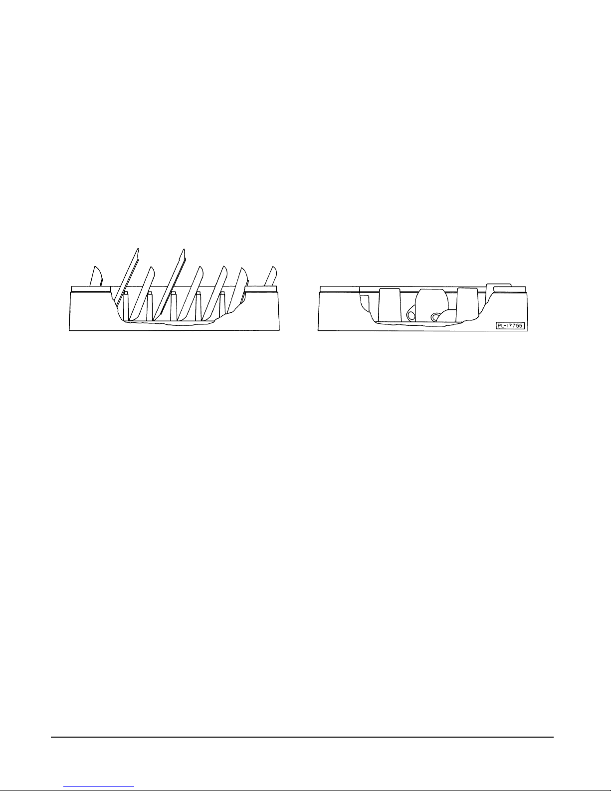
If the machine is equipped with an RS, CS, or PW unit, install the solid prewash strainer pan over the
overflow tube, flange side down and the lip toward the rear of the tank. Install one perforated strainer
pan, handle side up, across the rear of the tank. Install the other perforated strainer pan against the
load end of the tank and locate the flange into the notches on the solid and perforated strainer pans.
Drop in the perforated strainer basket (Fig. 16.)
Fig. 16 Fig. 17
Hang curtains on open hooks provided. Refer to the curtain diagram on pages 19 – 20 that corresponds
to your machine.
Move drain lever(s) down to close the drain(s) (Fig. 17), or close the door(s) to automatically push the
lever(s) down.
FILLING THE DISHWASHER
Water must be proper hardness. Recommended hardness range is 4 – 6 grains / gallon.
Turn the Power switch On (Fig. 1). Leave pumps Off until machine has completely filled.
If the machine is equipped with an RS, CS, or PW unit, the prewash tank will fill last, with overflow water
from the wash tank.
If the machine is equipped with steam heat, the mechanical ball valve (located between the drive motor
and the tank) must be opened by pulling the valve lever down.
– 21 –
Page 22

If the machine is equipped with gas heat, refer to STARTING THE GAS HEAT DISHWASHER, below.
The tank water temperature is regulated by the solid state thermostat. The thermostat is preset at the
factory and no adjustment should be required. If an adjustment is necessary, contact your local Hobartauthorized service office. Use thermometers for verification of proper water temperatures.
Minimum temperatures for all models are:
Single Tank Models
C44A/AW, C54A 160°F (Min.) –––– –––– 180°F (Min.)
CRS66A/AW, CRS76A
CPW80A/AW, CPW90A
CCS66A/AW, CCS76A
Two Tank Models
C64A, CRS86A, CCS86A, CPW100A 150°F (Min.) 160°F (Min.) –––– 180°F (Min.)
C88A, CRS110A, CCS110A, CPW124A
C64W, CRS86W, CCS86W, CPW100 150°F (Min.) 160°F (Min.) 160°F (Min.) 180°F (Min.)
C88W, CRS110W, CCS110W, CPW124W
Minimum temperatures for optional low-temperature operation are: Wash - 140°F; Rinse - 140°F; Final Rinse - 140°F.
WASH RINSE AUX RINSE FINAL RINSE
If the tank is accidentally drained before turning off the power switch, the float-controlled low-water
protector switch will automatically stop the tank heat. When the proper water level is returned, the tank
heat will be automatically started. DO NOT use the low-water protection as a power On-Off switch. The
heat MUST be turned Off at the Power switch when the machine is not in use.
Scatter the initial charge of detergent on the dishwasher strainer pans. Replenish as needed. When
an automatic detergent dispenser has been added (by private supplier), follow supplier’s instructions.
STARTING THE GAS HEAT DISHWASHER
1. STOP! Read the safety information on page 2 before operating this dishwasher.
2. Turn main gas supply to the dishwasher On.
3. Wait for 5 minutes to clear out any gas. If you then smell gas, STOP! Follow the safety information
on page 2.
4. If you don't smell gas, turn the manual gas valve On.
5. Turn the Power switch On (Fig. 1). Dishwasher will fill automatically (refer to AUTO FILL, page 6).
When tank is filled, the burner will ignite if heat is required. (The ignition system includes a 15second pre-purge period before ignition occurs.)
6. If the dishwasher will not operate, follow the instructions below to turn off the gas to the dishwasher.
Call your local Hobart service office or gas supplier.
To Turn the Gas-Powered Dishwasher Off:
Turn the Power switch Off. Turn the manual gas valve Off.
– 22 –
Page 23
DISHWASHING
After the machine has filled, start pumps by pushing the Motor switch On (Fig.1).
Pre-scrap dishes thoroughly to remove large food particles and debris. Never use steel wool on ware that
is to be loaded into the dishwasher.
Stack dishes in the racks. Do not stack dishes one on top of another as water must have free access to
both sides of every dish. Stand plates and dishes up edgewise as shown in Fig. 18. Cups, glasses, and
bowls should be inverted in open-type or compartment-type rack as shown in Fig. 19. Silverware and other
small pieces may be scattered loosely over the bottom of a flat-bottom rack.
Do not allow foreign objects to enter the unit, especially metallic contaminants.
Fig. 18 Fig. 19
When one rack has been loaded, slide it into the machine and start loading another. The operation of the
dishwasher is automatic. Each rack moves through the prewash, wash, and rinse zones, then out onto
the clean dish table. The rinse lever is actuated by the dish rack and automatically shuts off the final rinse
water when no rack is in the rinse zone.
Allow dishes to drain and air-dry before removing from rack.
Machines equipped with the optional conveyor dwell feature will allow you to stop the conveyor in order
to wash heavily soiled dishes for a longer time. When the dish rack reaches the wash chamber, turn the
Conveyor switch Off to stop the conveyor. To start the conveyor again, turn the Conveyor switch On.
An overload mechanism is provided that will shut off the conveyor drive motor should the racks jam or the
load become excessive. After the jam is cleared, push the Motor switch On to restart the dishwasher.
– 23 –
Page 24

CLEANING
The machine must be thoroughly cleaned at the end of each working shift, or at least twice a day. Use only
products formulated to be safe on stainless steel.
1. Turn the Motor and Power switches Off.
2. Open the door(s). Standard door interlock switches prevent machine operation with inspection door(s)
open.
3. Check the upper and lower final rinse nozzles, or auxiliary rinse nozzles (if so equipped) to make sure
they are free of lime and solids.
If the nozzles are clogged, open them by poking a straightened paper clip into the opening. Unscrew
and remove the rinse arm end cap (Fig. 20) and, with the splash curtains in place and the machine door(s)
closed, run an empty rack through the dishwasher as in normal operating procedure. When the rack
exits, open the machine door(s) and replace the rinse arm end cap(s).
NOZZLE
END CAP
Fig. 20
RINSE ARM
PL-52441
4. Open drain(s) by pulling drain lever(s) up (Fig. 17).
5. Remove wash arms. Remove wash arm end caps (Fig. 21) and push any nozzle obstructions into the
wash arms. Thoroughly flush the wash arms in a sink and replace the wash arm end caps (a twisting
action helps assure proper seating).
RETAINER
NOZZLE
CATCH
PIN
THREE SEGMENT ARMS ARE
USED ON SOME MODELS
FOUR SEGMENT ARM SHOWN
6. Clean off any scraps from machine walls.
7. Clean dish tables into the dishwasher.
8. Remove all strainer pans and strainer basket(s). Empty contents into garbage can or disposer and
thoroughly clean pans and basket(s).
9. Remove and clean pump intake strainer (Fig. 4).
END CAP
PL-52442
Fig. 21
– 24 –
Page 25

10.Remove final rinse pan strainer. Clean out pan and drain opening in pan bottom. Clean off strainer.
11.On C54A, CRS76A, CCS76A and CPW90A machines, remove both flowback strainer pans and
clean.
12.On Dual Rinse machines, remove the auxiliary rinse strainer and clean.
13. Remove curtains. Thoroughly scrub, rinse, and allow to dry at the end of each day’s operation. See
appropriate curtain diagram (pages 19 – 20) for proper curtain installation.
14.Thoroughly wash out the interior of the machine with a heavy-duty hose fitted with a squeeze valve.
Remove remaining soil with a cloth or soft brush and mild cleanser. Rinse again with hose. Do not
allow food soil to accumulate on the bottom of the tank.
15.Return all strainer pans, strainer basket(s), and the pump intake strainer to their original locations.
16.Install upper wash arms. Rest the manifold on the rear hanger bracket with the open end of the arm
next to the wash pipe and rotate the arm upward to latch it.
17. Insert the lower wash arm at an angle between the conveyor and install the retainer over the pin. Rotate
the arm toward the catch and engage the hook into the notch (Fig. 21).
18. Leave door(s) open and curtains removed while machine is not in use. This will allow the interior to air
out and dry.
DOs AND DON'Ts FOR YOUR NEW HOBART WAREWASHER
DO assure proper water hardness.
DO pre-scrap dishes thoroughly.
DO use only detergents recommended by your chemical professional.
DO at the end of the day, thoroughly cleanse the machine, rinse, and dry (leave door open).
DO closely follow your chemical professional's prescribed deliming schedule.
DO use only products formulated to be safe on stainless steel.
DO NOT over soften water (recommended water hardness is no less than 4 grains per gallon).
DO NOT use detergents formulated for residential dishwashers.
DO NOT allow food soil to accumulate on the tank bottom.
DO NOT exceed chemical manufacturer's recommended concentrations for detergent, sanitizer, rinse
aid, or lime scale remover.
DO NOT use steel wool to clean ware or warewasher surface.
DO NOT allow foreign objects to enter the unit, especially metallic contaminants.
NOTE: Failure to follow use, care, and maintenance instructions may void your Hobart warewasher
warranty.
– 25 –
Page 26

MAINTENANCE
WARNING: DISCONNECT ELECTRICAL SUPPLY AND PLACE A TAG AT THE DISCONNECT
SWITCH TO INDICATE THAT YOU ARE WORKING ON THE CIRCUIT BEFORE BEGINNING ANY
MAINTENANCE PROCEDURE.
Some machines may have more than one electrical power supply. Separate electrical power connection
is required for the Dual Rinse unit (if so equipped). All supplies MUST be disconnected.
VENT
When cool, check the vent of this dishwasher every six months for obstructions.
LUBRICATION
None required.
– 26 –
Page 27

TROUBLESHOOTING
NOTE: If symptom(s) persists after possible causes have been checked, contact your local Hobart
service office.
SYMPTOM POSSIBLE CAUSE
No Machine Operation.
Dishes Not Clean.
Leaking Valve (Except
Solenoid Type) Supplied by
Others.
1. Blown fuse or tripped circuit breaker at power supply.
2. Inspection door(s) not closed.
3. Conveyor may be jammed.
4. If Auto Timer was used, the timer may have expired.
5. If table limit switch is used, the switch may be tripped.
6. Manual overload protector tripped on pump motors or conveyor motor.
1. Insufficient wash water due to drain obstruction preventing proper drain
closing.
2. Worn or torn drain ‘‘O’’ ring allowing wash water to drain.
3. Missing end plug from wash arm.
4. Wash arm nozzle obstruction.
5. Water leaking past manifold ‘‘O’’ ring.
6. Loss of water pressure due to pump obstructions.
DISCONNECT ELECTRICAL POWER SUPPLY(IES) AND PLACE A TAG
AT THE DISCONNECT SWITCH TO INDICATE YOU ARE WORKING
ON THE CIRCUIT. Drain tank(s) and check for any obstruction at the pump
intake.
7. Incorrect water temperature. Check circuit breaker to electric heat supply,
or main steam valve. Make certain valve is completely open.
8. Incorrect detergent dispensing. Contact your detergent representative.
1. Foreign material preventing proper valve operation. A critical period is
soon after installation when pipe compound or metal shavings may lodge
at the valve seat. Shut off supply line. Unscrew and lift bonnet from valve
body. Clean valve and reassemble.
2. If problem is with a solenoid valve, it is recommended that you contact your
local Hobart service office.
Spotting of Silverware,
Glasses, and Dishes.
1. Improperly loaded racks.
2. Incorrect final rinse water temperature (min. 180° F).
3. Loss of water pressure due to pump obstruction.
DISCONNECT ELECTRICAL POWER SUPPLY(IES) AND PLACE A TAG
AT THE DISCONNECT SWITCH TO INDICATE YOU ARE WORKING ON
THE CIRCUIT. Drain tank(s) and check for any obstruction at the pump
intake.
4. Clogged wash arm nozzles.
5. Improper water hardness (4 - 6 grains/gallon is the recommended range).
6. Incorrect detergent for water type.
7. Clogged rinse nozzle(s).
8. Misaligned rinse arms. Rinse arms should be positioned so that the spray
pattern is slightly toward the center of the dishwasher. NOTE: All machines
may have alignment studs on the rinse arms that correspond to studs on
the rinse piping.
– 27 –
Page 28

SYMPTOM POSSIBLE CAUSE
Inadequate Rinse.
Continuous Rinse
Operation.
1. Dirty line strainer (Fig. 10) causing reduced water flow. Turn off water supply,
remove strainer cap, withdraw and clean screen. Reassemble.
2. Low supply line pressure.
3. Clogged rinse nozzle(s).
1. Rinse actuator (Fig. 22) not moving freely.
DISCONNECT ELECTRICAL POWER SUPPLY(IES) AND PLACE A
TAG AT THE DISCONNECT SWITCH TO INDICATE YOU ARE WORKING
ON THE CIRCUIT. Check actuator for movement.
Fig. 22
2. Check for foreign object in mechanism, i.e., silverware.
3. Rinse valve failed or jammed open. Contact your local Hobart service office.
No Wash Tank Heat.
No or Slow Fill.
1. The machine is equipped with low water safety devices which shut off heat
if water level drops. Check for proper water level.
2. Circuit breaker to heat system tripped.
3. Check heat float for debris and free movement.
4. Steam supply valve not open completely.
5. Overtemp protector tripped. Contact your local Hobart service office.
1. Dirty line strainer (Fig. 11) causing reduced water flow. Turn off water supply,
remove strainer cap, withdraw and clean screen. Reassemble.
2. Make sure doors are closed.
3. Check both upper and lower fill floats for debris and free movement.
4. Problem with solenoid valve.
SERVICE
Contact your local Hobart-authorized service office for any repairs or adjustments needed on this
equipment. If a gas orifice fitting is to be adjusted or replaced, have it serviced by qualified Hobartauthorized service personnel. Long-term service contracts are available on this and other Hobart
products.
FORM 17791 Rev. L (June 2000) PRINTED IN U.S.A.
– 28 –
 Loading...