

Page 1

Page 2
CHH50
CHH60
CHH70
Dishwasher
Installation / Operation
Spare Parts List
Wiring Diagram
jw-06-2006
Page 3

USE AND MAINTENANCE MANUAL
page 2
CONTENTS
CHAP.1 INTRODUCTION .......................................................................................... 3
CHAP.2 INSTALLATION............................................................................................ 3
2.1 HANDLING AND U N P ACKING. ...................................................................................... 3
2.2 ELECTRICAL C O N N E C TION. ......................................................................................... 4
2.3 WATER CONNE C T I O N . ................................................................................................... 4
2.4 DRAIN CONNE C T I O N . ..................................................................................................... 5
2.5 ADJUSTMENTS ................................................................................................................. 5
2.6 RINSE-AID DISPENSER ...................................................................................................... 5
2.7 DETERGENT........................................................................................................................ 6
CHAP.3 SAFETY RECOMMENDATIONS.................................................................... 7
3.1 RESIDUAL RISKS AND WARNINGS ................................................................................... 7
3.2 SAFETY DEVICE.................................................................................................................. 7
CHAP. 4 USE OF MACHINE ....................................................................................... 8
4.1 DESCRIPTION OF THE COMMANDS ................................................................................. 8
4.1.1 Automatic water drainage (optional)….………………………………….……………….……… 9
4.2 USING THE MAC H I N E . .................................................................................................... 9
4.3 END OF CY C L E O PERATIONS.................................................................................... 10
CHAP.5 MAINTENANCE.......................................................................................... 11
5.1 GENERAL RULES . .......................................................................................................... 11
5.2 PERIODIC MAINTENANCE (TO BE DONE AT LEAST EVERY 20 DAYS) ....................... 11
CHAP.6 DISMANTLING ........................................................................................... 12
6.1 DISMANTLING T H E M A C HINE .................................................................................... 12
Page 4
USE AND MAINTENANCE MANUAL
page 3
CHAP.1 INTRODUCTION
The warnings contained in this manual provide important
information for safely installing, using and servicing this
machine.
The operator is required to read this manual before starting
any operation involving handling, installation, use,
maintenance or disassembly of the machine. This manual
must be kept intact and in a safe place for frequent
consultation.
CHAP.2 INSTALLATION
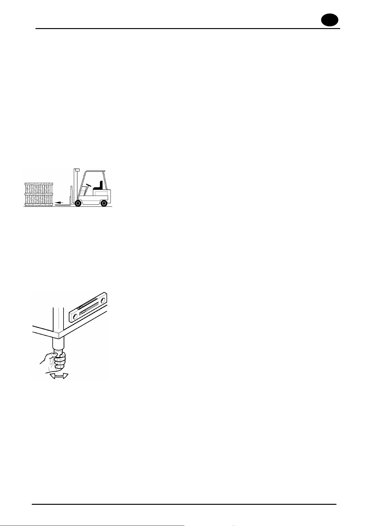
2.1 HANDLING AND UNPACKING
x
Move the machine very carefully using a forklift.
x
Make sure the equipment is not damaged, if it is immediately
inform the dealer and shipper. If in doubt do not use the
machine until it has been checked by professionally trained
personnel.
GB
x
Move the machine to the site where it will be used and
remove the packing.
Packing materials (plastic bags, polystyrene,
nails) can be dangerous and must be kept out of
the reach of children.
x The installation must be carried out according to the
manufacturer’s instructions and by professionally trained
personnel.
x Only a fixed connection is suitable for this equipment.
x Position the machine and level it perfectly using the feet.
x The flooring must be suitable for the overall weight of the
machine.
x Follow the indications on the installation drawing and set-up
the electrical, water and drain systems in the wash area.
Page 5
GB
page 4
USE AND MAINTENANCE MANUAL
H
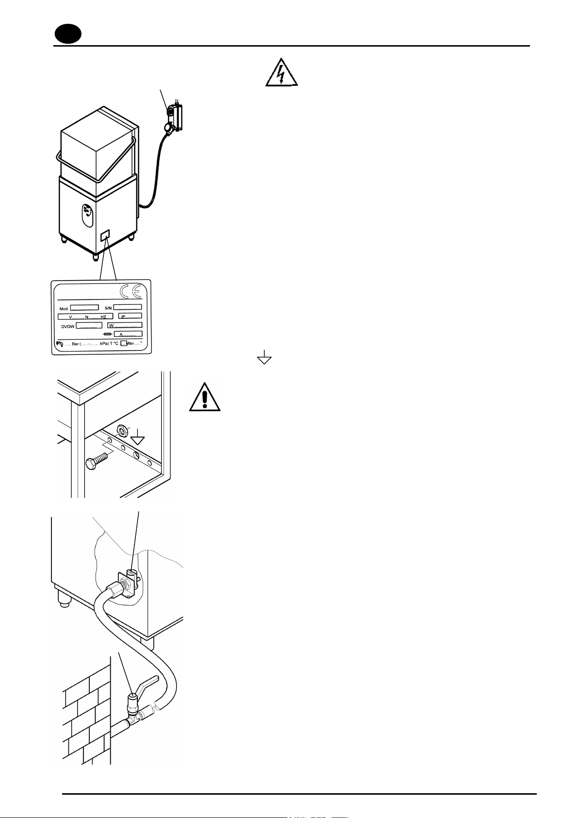
2.2 ELECTRICAL CONNECTION
1. Connection to the power supply must be made with a main
switch (H) it must be omnipolar and interrupt all contacts
including neutral. There must be a distance of at least 3
mm between open contacts, and it must have a thermal
magnetic safety switch or fuses which are able to
withstand the maximum power indicated on the plate.
2. Make sure that the power supply corresponds to that on
the technical features plate on the right side of the
machine.
3. Use an effective earthing system in compliance with local laws to
protect the safety of the operators and not damage the machine.
4. Do not use adapters, multiple sockets or extension cords.
5. The equipment must be included in an equipotential
system, and connected using a screw marked with the
symbol. The equipotential wire must be 10 mm² .
V
If the power supply cable (provided with the equipment)
needs to be replaced use another H07RN-F type with the
same dimensions.
For additional information see the wiring drawing.
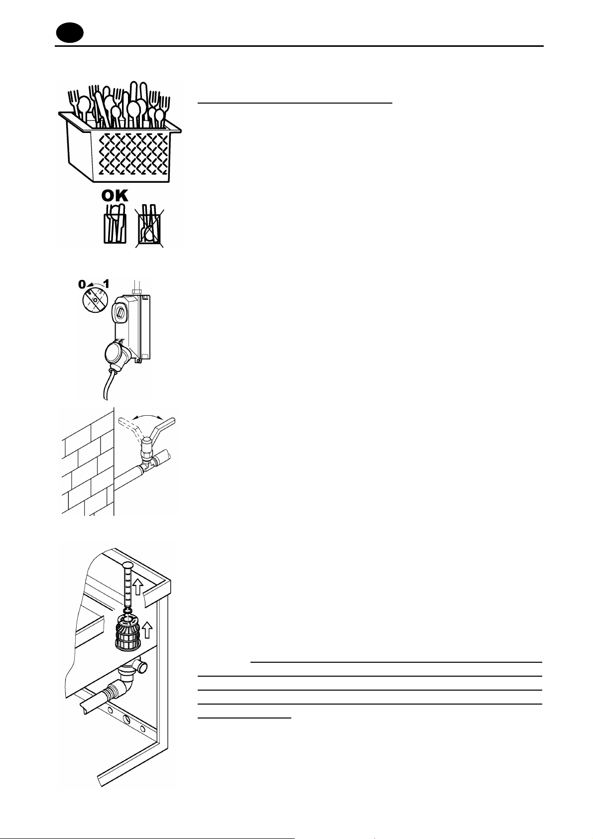
2.3 WATER CONNECTION
E
Set-up the site according the attached plumbing drawing.
Before connecting the equipment make sure that a gate valve
has been placed between the water supply and the
equipment so that the water can be turned off if required or
for repair work.
Use a hose to connect the solenoid valve (E) to the gate
valve (V) and make sure that the delivery is not less than
20l/min.
Check that the temperature and water pressure correspond
to what is shown on the technical specifications plate.
If the water is harder than what is listed in the chart, it is
advisable to install a decalcifier upline from the solenoid
valve.
If there are high concentrations of very conductive minerals in the
water, it is advisable to install a demineralization system calibrated to
the hardness shown in the following chart.
Page 6
USE AND MAINTENANCE MANUAL
page 5
Specification
From
To
Hardness
Residual
Minerals
French degrees
German degrees
English degrees
Parts per million
Maximum
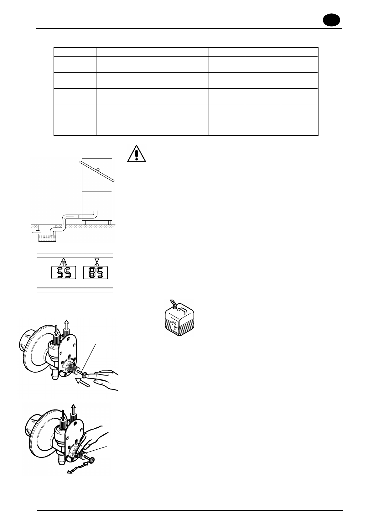
Gravity for all models, except EH70, so the drain needs to be
situated below the base of the machine. Model EH70 requires a stand-pipe
The drain pipe needs to be connected to a drain- trap built
into the floor.
The drain dimensions are shown in the installation drawing.
2.5
f
°dH
°e
ppm
mg/l
2.4
ADJUSTMENTS AND CHECKS
5
4
5
70
300/400
DRAIN CONNECTION
10
7’5
9,5
140
A
The temperature of the wash tank is regulated by a fixed thermostat at
about 55° C. This temperature ensures proper action by the chemicals
contained in industrial dishwashing detergents.
The boiler temperature set by a fixed thermostat is about 85° C.
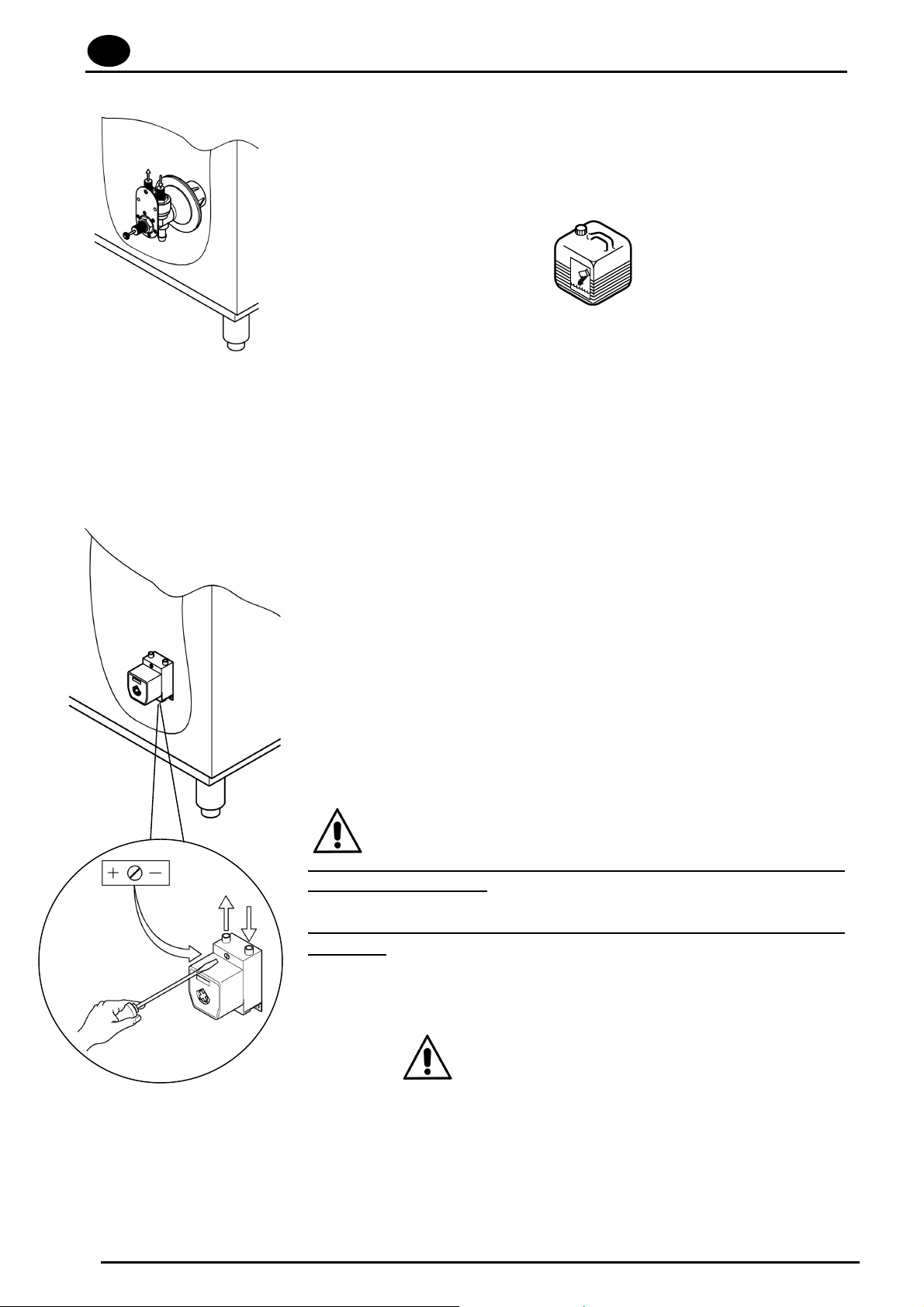
2.6 RINSE-AID DISPENSER
Before adjusting, the dispenser and hose need to be filled
using the primer button (A).
To adjust use the ring nut (B) situated at the center of the
dispenser, rotating clockwise reduces the quantity,
counterclockwise increases it.
The dispenser must not operate empty
An excessive amount of rinse agent causes bluish stripes on the
dishes and creates foam in the wash tank.
B
Page 7
GB
page 6
USE AND MAINTENANCE MANUAL
If the glassware is covered with droplets of water and it drys rather
slowly this means that the amount of rinse agent is insufficient.
7 cm. of tubing = 1 gram of product
2.1 DETERGENT
Equipment without a detergent dispenser
Put the amount of detergent recommended by the
manufacturer into the tank. Depending on the type of
detergent this may vary from 2 to 4 gr/lt of water in the tank.
Detergent needs to be added approximately every 5 washes
as per the manufacturer’s instructions.
The above amounts are for water with a hardness of 5-10°F
(French degrees).
A
Models EH60/70 and CHH50 are equiped with detergent dispenser
Regulations:
A trimmer (A) allows to determine the «ON-OFF» time and
consequently the amount of detergent required.
x Turning the adjustment trimmer clockwise or counter-clockwise will
respectively decrease or increase the amount of rinse aid it
delivers.
x To optimise the calibration, evaluate the results of some washing
cycles.
BE CAREFUL!
The level in detergent tank must not get empty or filled with corrosive
or inadequate products.
The warranty does not cover damages caused by an improper use of
dispenser.
CHAP.3 SAFETY RECOMMENDATIONS
3.1 RESIDUAL RISKS AND WARNINGS
x Never open the door quickly if the cycle has not finished.
x Do not put bare hands into the wash solution.
x Never remove the machine panels if the power upline has not been turned off.
x The professionally trained personnel who install the machine and connect the electricity,
will explain to the user how to operate the machine and which safety measures to use.
x The installer will provide practical demonstrations and leave written instructions which are provided with
the machine.
Page 8
USE AND MAINTENANCE MANUAL
page 7
x This machine is only to be used for the purpose for which it was designed.
Any other use is considered improper and dangerous.
x The machine is not to be used by untrained personnel.
x Never use the machine if any of the protections (microswitches, panels or other) provided
by the manufacturer are missing.
x Do not use the machine to wash objects not compatible with those indicated by the
manufacturer.
x All repair work must be done by the manufacturer or an authorized service center using
original spare parts.
x Failure to observe this may affect the safety of the machine.
x The power supply should be turned off when the machine is not being used.
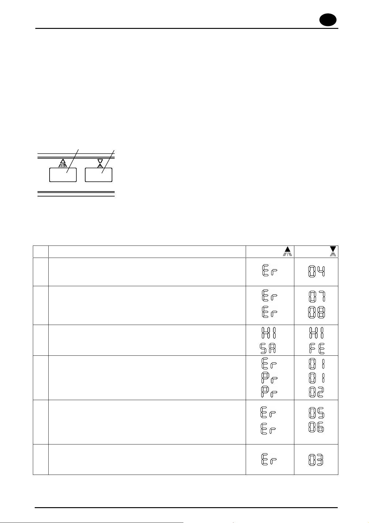
3.2 SAFETY DEVICE
56
The board can recognize various breakdowns.
Faults are easily seen from the messages on the screen (5 and 6) and from any interruption of the
operations in progress only in cases (1 and 3) listed below
WARNING! Turning the machine off and then on again resets the warning, which will appear again if
the problem has not been resolved.
Display on the Message
PROBLEM: Tank (6) Boiler (5)
TANK NOT FILLED OR OVERFILLED
1
(if t10 min have elapsed, correct level of water has not been reached in the
tank)
BOILER PROBE FAILURE
2
(if the probe is not connected correctly or damaged)
(if the probe is short circuited or damaged)
OVERTEMPERATURE
3
(excessive boiler and tank temperature)
(intervention safety thermostat)
4
(Insufficient rinse pressure)
(Excessive rinse pressure)
RINSE
(Rinse not effected)
TANK PROBE FAILURE
5
6
(if the probe is not connected correctly or damaged)
(if the probe is short circuited or damaged)
BOILER
(Boiler resistor failure)
(Heating overtime)
Page 9
GB
page 8
USE AND MAINTENANCE MANUAL
1
2
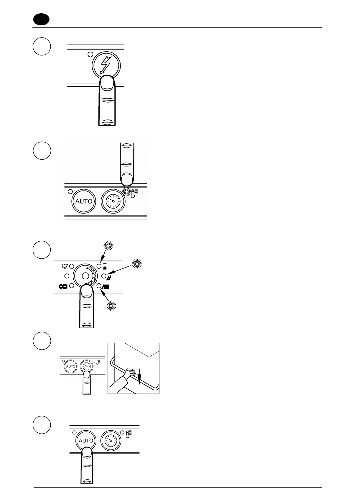
Chap. 4 USE OF MACHINE
4.1 DESCRIPTION OF THE COMMANDS
1. To turn the machine on, press the button
indicated at left/right
(the corresponding warning light will light
up)
.
2. When the light turns off, the machine is ready
to use.
3
4
Short cycle
Medium cycle
Ciclo intensive
3. Press the button indicated at left/right to
select the items to wash. The light turns on
in accordance with the amount of time
selected.
NB: choose the " v " for longer wash
cycles.
4. Press the button indicated at left/right and
close the door, the machine will start
automa-tically.
interrupt the "
sequence 3 for new wash programs).
NB: press the button to
v
" cycle (repeat
5
5. If you want cycles to start when you close
the hood, push the button and the
corresponding light will turn on
Page 10
USE AND MAINTENANCE MANUAL
page 9
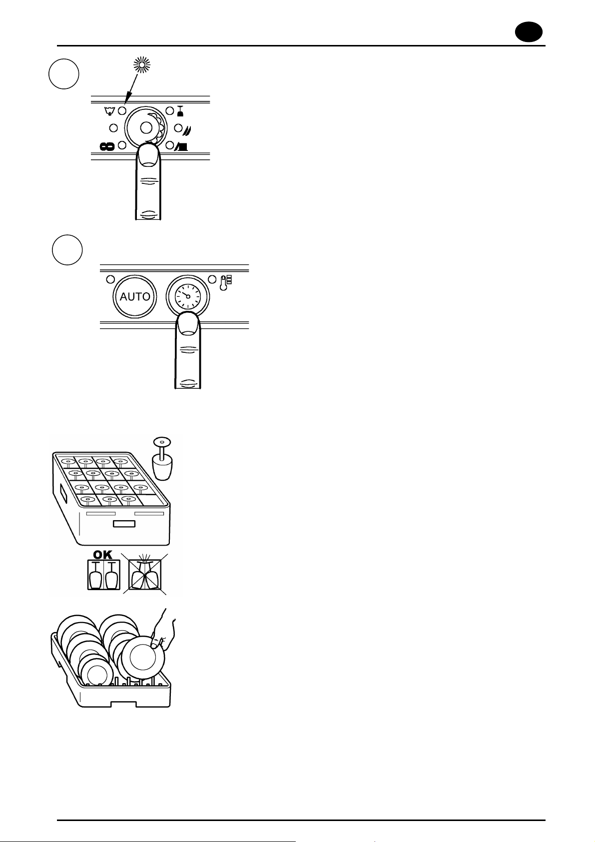
1
2
4.1.1 Automatic water drainage
(optional)
1. Press the button indicated at
left/right and select the drainage
programme (the corresponding
warning light will light up).
2. Press the button indicated at
left/right and the machine will
automatically drain the water out of
the machine.
4.2 USING THE MACHINE
Pour the proper amount of detergent in the wash tank according to the
producer’s instructions.
The detergent must be the industrial type or possibly foamless.
Never put your bare hands in the wash water; place the cups and the
glasses upside down in the baskets. Place the dishes in the proper
basket with support pins and their inner surface must be facing up.
Place the silverware and the coffee spoons with the handles facing
down.
Never place silverware and stainless steel cutlery in the same basket.
This could cause the silver to burnish and the stainless steel to
corrode.
Use the proper baskets specifically designed for the different type of
glassware (dishes, glasses, cups, silverware etc.). To save on
detergent and electricity only wash when the baskets are full, but do
not overload them. Avoid stacking glassware.
Page 11
GB
page 10
USE AND MAINTENANCE MANUAL
WE RECOMMEND TO PRE-CLEAN the glassware in order to
minimize maintenance. The quality of final wash results will be greatly
improved by first removing food particles, lemon peels, toothpicks,
olive pits, etc. which could partially clog the pump filter and impair
washing efficiency.
We recommend washing the glassware before food particles dry
on its surface. It is good practice, when dried food waste is
involved, to first soak the glassware and silverware before
introducing them into the machine.
4.1 END OF CYCLE OPERATIONS
x Remove tension from the machine.
x Lift the hood and extract the rack clean dishes.
x Drain the water from the tank by lifting the overflow-pipe. For the
model with drain pump please follow the operations described in the
«Use instructions» paragraph.
x Disconnect the main switch of the equipment.
x Close the «rolling shutter valve» for the hydraulic connection.
x Remove the filters clean them under a water jet with a nylon brush.
x Pay attention not to let any dirtiness rests on the bottom of the
drain pump filter inside the tank. Clean the tank with a moderate water
jet. Wash outside surfaces when are cold with non-abrasive products
which are especially studied for steel maintenance.
REMARK: Do not wash the equipment with direct jet or at
another pressure because eventual infiltrations to the electric
components may harm the regular working of the equipment or
of the single safety systems, and penalty for this would be the
loss of guarantee.
Page 12

USE AND MAINTENANCE MANUAL
page 11
CHAP. 5 MAINTENANCE
5.1 GENERAL RULES
The machine are designed to reduce maintenance requirements. It is
necessary to observe the following rules to make the machine last
long, and work without problems.
In any case, it is necessary to observe the following rules to make the
machine stay in perfect working order:
x keep the machine clean and in good condition
x avoid making temporary or urgent repairs frequently
It is very important to observe the maintenance directions; check all
the different parts of the machine periodically, so that no anomaly can
occur, thus anticipating the time and equipment needed for any
maintenance work.
Before cleaning turn off the power.
5.2 PERIODIC MAINTENANCE (to be done at least every 20 days)
To make operations following easier, the rack-holder frame can be
removed from its seat.
x Remove the upper and lower rinse arms, by unscrewing the
fastening.
x Unscrew and clean all the sprayers and put them back in their
place.
x Remove the upper and lower wash-arms by unscrewing the rinse
pin , clean and rinse them.
x Remove the wash pump filter, clean it and rinse it.
x Thoroughly clean the wash tank.
x Leave the appliance lid open for the whole resting period.
x Lime deposits and scale will build up on the inner surfaces of the
boiler, tank and pipelines due to calcium and magnesium salts
present in the water. These scales and deposits can prejudice
proper apppliance operation.
x The appliance must be periodically descaled and we recommend
that this must be done by an expert.
Page 13

GB
page 12
USE AND MAINTENANCE MANUAL
x Grease steel surfaces with vaseline oil whenever the appliance will
be inactive for a long period of time.
x Have an expert drain all the water out from the boiler and the wash
pump to avoid the danger of ice formation.
x If the machine does not operate properly or in case of trouble,
call a service center authorized by the manufacturer of the
appliance or by his Dealer.
CHAP. 6 DISMANTLING
6.1 DISMANTLING THE MACHINE
Our machines are not made of materials that require particular
disposal procedures.
Page 14

CHH50
CHH60
CHH70
Dishwasher
Spare Parts List
jw-06-2006
Page 15

CHH50 - EH60 - EH70
Machine Body
Electrical components
Components in the tank
Wash pump
Page 16

CHH50 - EH60 - EH70
80422
139321-470
80331
926243
926108
80423
80420
80325
80329
80162
139321-475
139321-552
927088
139321-474
80190
80105
80105
80027
80240
41042
926009
80071
80023
41042
80072
80078
926117
80079H
139321-663
139321-667
139321-668
139321-664
139321-666
139321-669
139321-670
139321-671
139321-672
139321-675
139321-474
139321-678
139321-674
139321-674
139321-676
139321-677
139321-679
139321-665
139321-680
139321-677
139321-681
139321-682
139321-683
139321-684
80998
139321-901
3
Page 17

CHH50 - EH60 - EH70
80372
DER111
139321-487
220011
CWP2
81001
CWP2
926286
H228048
DEF4
139321-451
215022
H228047
80350
231014
DTC112NO
929115
80372
220011
DWS99
H228048
H228047
139321-456
DEF4
81001
215023
215022
CWP3
CN1
80528
80542
80541
CHH50
EH60
EH70
139321-685
139321-686
139321-582
139321-687
139321-688
139321-689
139321-601
139321-690
139321-691
139321-687
139321-600
139321-692
139321-693
139321-685
139321-687
139321-582
139321-687
139321-601
139321-600
139321-694
139321-700
139321-696
139321-697
139321-695
139321-698
139321-699
139321-591
139321-688
139321-689
139321-690
139321-691
DEF71
139321-902 (800mA)
DEF72
139321-903 (315mA)
4
Page 18

80149 (CHH50 / EH60)
80159 (EH70)
80152 (EH70)
80177
80282
80184
211002AG
80316
139321-452(CHH50/EH60)
139321-476 (EH70)
468151
139321-550
926189
H775489-1
231014
139321-450*
139321-473 * Drain Pump Kit
136020
456040
143136
80186
80470
80188 (CHH50 / EH60)
80187 (EH70)
139321-472 (EH70)
139321-471 (EH60)
139321-548 (CHH50)
80182
139321-192
80249 (CHH50 / EH60)
80250 (EH70)
80237
441009
( * ) EH70 Model Only
5
CHH50 - EH60 - EH70
139321-701 (CHH50 / EH60)
139321-702 (EH70)
139321-703 (EH70)
139321-839
139321-906
139321-904
139321-905
139321-915
139321-916
139321-918
139321-917
139321-925
139321-919
139321-923
139321-924
139321-920
139321-921
139321-914
139321-907
139321-908
139321-909
139321-913
139321-910
139321-911
139321-912
139321-587
139321-591
139321-1110 Pump Only
*FITTED AS STD ON
Page 19

EH70
468165
437078
429050
437025
41167
143010
429036
80575
926129
80314
929085
206010
143005
927326
H142277
139321-464
139321-490
80538
139321-37
139321-53
230020C
DRT140
80530
929171
139321-521
929198
6
139321-766
139321-780
139321-767
139321-653
139321-652
139321-930
139321-927
139321-926
139321-942
139321-931
139321-941
139321-615
139321-932
139321-933
139321-934
139321-935
139321-936
139321-938
139321-937
139321-939
139321-940
139321-928
139321-929
Page 20

80314
139321-957 (EH70)
139321-956 (CHH50 - EH60)
139321-483
139321-928
139321-943
139321-943
139321-944
139321-944
139321-945
139321-946
139321-947
139321-947
139321-948
139321-948
139321-949
139321-949
139321-950
139321-951
139321-952
139321-953
139321-954
139321-955
139321-956
139321-957
139321-918
139321-920
CHH50 - EH60 - EH70
80311
DWT312
80379
80375
80371
80380
80371
80310
80378
927068
DWT312
CGR2025
80376
CGR2025
80373
80365
80374
80380
80282
80316
7
80370
80377
80311
Page 21

DEC220L
139321-509
139321-958
139321-974
139321-960
139321-961
139321-962
139321-963
139321-964
139321-965
139321-966
139321-967
139321-471
CHH50 - EH60 - EH70
926083
RAC135
926255
RAT72
RAG62
124031
RAC436
80112
CHH50
RAG72
926086
139321-478
80114
EH 60
8
Page 22

RAC74
139321-969
139321-970
139321-964
139321-971
139321-972
139321-967
139321-973
139321-472
EH70
RAV74
926083
RAG74
RAT210
926086
926084
80116
EH 70
9
Page 23

23/09/03
Product Modification Note , from today’s date we have done the following modification:
Codes subject to the modification
RV82HUK (hobart u.k.)
Modification ‘s Description
For all hood type models ,
We have exchanged the current pump cod. 139321-472 built by LGB , with the wash pump
Code 80115 built by FIR.
The two wash pumps are completely interchangeable as a whole part , but
the single internal components will be different , so we have attached the new
spare part catalogue page for the FIR wash pump code 80115.
10
Page 24

Wash Pump
(Modification - 23.09.03)
80124
80123
EH70
80122
80121
80120
80119
80115 (Fir) Wash Pump Assy
Modification from 23.09.2003
(see att Note)
80118
11
Page 25

929173
139321-975
139321-976
139321-977
139321-978
139321-979
139321-490
CHH50 - EH60 - EH70
929182
RAG426
RAT124
929186
929167
12
Page 26

CHH50 - CHH60 - CHH70
Drain Pump Assy
Drain Pump 220-240V 50Hz - 139321-1110
Drain Pipe 2000mm (drain pump to drain) DZS151 - 139321-968
Drain Pipe (from machine to pump) 127056 - 139321-969
Jubilee Clip 40/60 -
Jubilee Clip 20/32 - 166513-6
Bolt 6MAx12 -
Lockwasher D6 - LWM-E-3-4
Timer Card (tally drain timer) -
Timer (drain timer) -
Page 27

As continued product inprovement is a policy of HOBART, specifications are subject to change with-out notice.
00.00.2003-Issue-1
Page 28

CHH50 / EH60
CHH50
EH60
Page 29

SIMBOLO DESCRIZIONI DESCRIPTIONS BESCHREIBUNGEN
EH60 / CHH50
A1/43 SCHEDA CONTROLLO ELETTRONICA FICHE DE CONTROLEELECTRONIQUE
A2 PANNELLO COMANDI TABLEAU DE COMMANDES
B1 SONDA RESISTENZA VASCA THERMOSTAT RESISTENCE DE CUVE
B2 SONDA RESISTENZA BOILER THERMOSTAT RESISTANCE BOYLER
B3 PRESSOSTATO LIVELLO VASCA PRESSOSTAT NIVEAU CUVE
B4 LIVELLOSTATO BOILER INT. A ELOTEUR
F2 FUSIBILE COMANDI FUSIBLE
F1 PROTEZIONE TERMICA ELETTROPOMPA PROT. TERMIQUE MOTEUR EL. POMPE
KM1 TELERUTTORE ELETTROPOMPA LAVAGGIO TELEREUPTEUR ELECTROPOMPE DE LAVAGE
KR1 TELERUTTORE RESISTENZA BOILER TELERUPTEUR RESISTANCE SURCHAFFEUR
KR2 TELERUTTORE RESISTENZA VASCA RELAIS RESISTENCE DE CUVE
KR3 TELERUTTORE SICUREZZA TELERUPTEUR DE SECURITE SURCHAFFEUR
M1 ELETTROPOMPA LAVAGGIO ELECTROPOMPE LAVAGE
M2 ELETTROPOMPA AUMENTO PRESSIONE ELECROPOMPE SURPRESSEUSE DE RINCAGE
M5 MOTORE DOSATORE DETERSIVO MOTEUR DOSEUR TENSIOACTIF
P1 PULSANTE PARTENZA AUTOMATICA INTERREPTEUR DEMARRAGE AUTOMATIC
P2 PULSANTE SELETTORE CICLO SELECTEUR CYCLE
P3 PULSANTE LINEA INTERRUPTEUR DE LIGNE
R1 RESISTENZA BOILER RESISTANCE SURCHAUFFEUR
R3 RESISTENZA VASCA RESISTANCE CUVE DE LAVAGE
S1 TERMOSTATO SICUREZZA BOILER THERMOSTAT DE SECURITE DU BOYLER
S2 TERMOSTATO SICUREZZA VASCA THERMOSTAT SECURITE CUVE
S3 MICROINTERRUTTORE MAGNETICO MICROINTERRUPTEUR MAGNETIQUE
Y2
ELECTRONIC CONTROL UNIT ELEKTRONISCHE BEDIENUNGSKARTE
CONTROL PANEL BEDIENUNGSPANEEL
PROBE TANK HEATER THANKHEIZUNGTHERMOSTAT
BOOSTER HEATER THERMOSTAT BOILERHEIZUNG -THERMOSTAT
TANK PRESSURE SWITCH DRUCKSCHALTER TANK-NIVEAUREGLER
BOOSTER FLOAT SWICTH SCWINNERSCHALTER
COMMAND FUSE SICHERUNGEN
EL. WASH PUMP THERMAL PROTECTION THERMISCHER MOTORPUMPESCHUTZ
WASH ELECTROPUMP REMOTE-CONTROL FERNSCHALTER DER WASCH-ELEKTROPUMPE
BOOSTER HEATER REMOTE -CONTROL FERNSCHALTER DER BOILER-HEIZUNG
RELAY FOR TANK HEATER ELEMENT. NACHSPUELHEIZUNGSRELAIS.
SAFETY HEATER REMOTE-CONTROL SICHERHEITS-FERNSCHALTER DES BOILERS
WASH MOTOR PUMP WASCH-MOTORPUMPE
RINSE BOOSTER PUMP DRUCKSTEIGERUNGSPUMPE
RINSE AID DISPENSER MOTOR NACHSPÜLUNGSMITTELDOSIERGERÄT-MOTOR
AUTOMATIC START PUSH BOTTON AU TOMATISCHER START WAEINSCALTER
CYCLE COMMUTATOR WAEHLSCHALTER FUER WASCHVORGANGSDAUDER
MAIN SWITCH NETZSCHALTER
BOOSTER HEATER HEATING ELEMENT BOILERHEIZUNG
WASH TANK HEATING ELEMENT WASCHTANKHEIZUNG
SAFETY BOOSTER HEATER THERMOSTAT BOILER -SICHERHEITS-THERMOSTAT
TANK SAFETY HEATER THERMOSTAT SICHERHEITS- TANKTHERMOSTAT
MAGNETIC MICROSWITCH MAGNETISCHER MIKROSCHALTER
ELETTROVALVOLA RIEMPIMENTO BOILER ELECTROVALVE REMPLISSAGE SURCHAUFFEUR
BOILER FILLING ELECTRIC VALVE SOLENOIDVENTIL DER BOILERFÜLLUNG
Page 30

EH70
Page 31

SIMBOLO DESCRIZIONI DESCRIPTIONS BESCHREIBUNGEN
EH 70
A1/43 SCHEDA CONTROLLO ELETTRONICA FICHE DE CONTROLEELECTRONIQUE
A2 PANNELLO COMANDI TABLEAU DE COMMANDES
B1 SONDA RESISTENZA VASCA THERMOSTAT RESISTENCE DE CUVE
B2 SONDA RESISTENZA BOILER THERMOSTAT RESISTANCE BOYLER
B3 PRESSOSTATO LIVELLO VASCA PRESSOSTAT NIVEAU CUVE
B4 LIVELLOSTATO BOILER INT. A ELOTEUR
F1 PROTEZIONE TERMICA ELETTROPOMPA PROT. TERMIQUE MOTEUR EL. POMPE
F2 FUSIBILE COMANDI FUSIBLE
KM1 TELERUTTORE ELETTROPOMPA LAVAGGIO TELEREUPTEUR ELECTROPOMPE DE LAVAGE
KR1 TELERUTTORE RESISTENZA BOILER TELERUPTEUR RESISTANCE SURCHAFFEUR
KR2 TELERUTTORE RESISTENZA VASCA RELAIS RESISTENCE DE CUVE
KR3 TELERUTTORE SICUREZZA TELERUPTEUR DE SECURITE SURCHAFFEUR
M1 ELETTROPOMPA LAVAGGIO ELECTROPOMPE LAVAGE
M2 ELETTROPOMPA AUMENTO PRESSIONE ELECROPOMPE SURPRESSEUSE DE RINCAGE
M5 MOTORE DOSATORE DETERSIVO MOTEUR DOSEUR TENSIOACTIF
P1 PULSANTE PARTENZA AUTOMATICA INTERREPTEUR DEMARRAGE AUTOMATIC
P2 PULSANTE SELETTORE CICLO SELECTEUR CYCLE
P3 PULSANTE LINEA INTERRUPTEUR DE LIGNE
R1 RESISTENZA BOILER RESISTANCE SURCHAUFFEUR
R3 RESISTENZA VASCA RESISTANCE CUVE DE LAVAGE
S1 TERMOSTATO SICUREZZA BOILER THERMOSTAT DE SECURITE DU BOYLER
S2 TERMOSTATO SICUREZZA VASCA THERMOSTAT SECURITE CUVE
S3 MICROINTERRUTTORE MAGNETICO MICROINTERRUPTEUR MAGNETIQUE
Y2
ELECTRONIC CONTROL UNIT ELEKTRONISCHE BEDIENUNGSKARTE
CONTROL PANEL BEDIENUNGSPANEEL
PROBE TANK HEATER THANKHEIZUNGTHERMOSTAT
BOOSTER HEATER THERMOSTAT BOILERHEIZUNG -THERMOSTAT
TANK PRESSURE SWITCH DRUCKSCHALTER TANK-NIVEAUREGLER
BOOSTER FLOAT SWICTH SCWINNERSCHALTER
EL. WASH PUMP THERMAL PROTECTION THERMISCHER MOTORPUMPESCHUTZ
COMMAND FUSE SICHERUNGEN
WASH ELECTROPUMP REMOTE-CONTROL FERNSCHALTER DER WASCH-ELEKTROPUMPE
BOOSTER HEATER REMOTE -CONTROL FERNSCHALTER DER BOILER-HEIZUNG
RELAY FOR TANK HEATER ELEMENT. NACHSPUELHEIZUNGSRELAIS.
SAFETY HEATER REMOTE-CONTROL SICHERHEITS-FERNSCHALTER DES BOILERS
WASH MOTOR PUMP WASCH-MOTORPUMPE
RINSE BOOSTER PUMP DRUCKSTEIGERUNGSPUMPE
RINSE AID DISPENSER MOTOR NACHSPÜLUNGSMITTELDOSIERGERÄT-MOTOR
AUTOMATIC START PUSH BOTTON AU TOMATISCHER START WAEINSCALTER
CYCLE COMMUTATOR WAEHLSCHALTER FUER WASCHVORGANGSDAUDER
MAIN SWITCH NETZSCHALTER
BOOSTER HEATER HEATING ELEMENT BOILERHEIZUNG
WASH TANK HEATING ELEMENT WASCHTANKHEIZUNG
SAFETY BOOSTER HEATER THERMOSTAT BOILER -SICHERHEITS-THERMOSTAT
TANK SAFETY HEATER THERMOSTAT SICHERHEITS- TANKTHERMOSTAT
MAGNETIC MICROSWITCH MAGNETISCHER MIKROSCHALTER
ELETTROVALVOLA RIEMPIMENTO BOILER ELECTROVALVE REMPLISSAGE SURCHAUFFEUR
BOILER FILLING ELECTRIC VALVE SOLENOIDVENTIL DER BOILERFÜLLUNG
Page 32

12345678
12345678
12345678
12345678
12345678
12345678
CHH50 (electrical configuration data)
Single phase configuration 6 kW
**
82
81
80
E
*
N
*
not used
L3
L2
*
L1
*
* Links must be installed as shown (not supplied)
Three phase configuration 9 kW
E
not used
Boiler heater
**This wire (is tied back)
needs to be connected (N)
Note: the copper links must
be positioned as shown
80 81 82
Boiler heater
82
81
80
N
L3
L2
L1
Bit switch settings
on
off
1 2 3 4
Note: the copper links must
be positioned as shown
80 81 82
1 = Temperature check - (waits for boiler)
2 = Drain pump (option)
3 = Boiler standby - (holding temp 50ºC)
4 = Boiler heating - (on or off)
Page 33

DISHWASHER TECHNICAL SPECIFICATIONS
EF40 EH60 EH70 EUT30 EUT60
Drain size 22MM 50MM 50MM 50MM 2"
Drain hose length 1,5M 1,80M 1,80M 1,80 No Hose
Water connection 3/4" 3/4" 3/4" 3/4" 3/4"
Water hose length 1,5M 2M 2M 2M 2M
Water pressure 1-4BAR 1-4BAR 1-4BAR 1-4BAR 1-4BAR
Water temp 15-55C 15-55C 15-55C 15-55C 15-55C
Total KW loading 3P N/A 9.1KW 11.1KW 8.0KW 15.0KW
Total KW loading 1P 5,5KW/2,7KW 6.5KW N/A N/A N/A
Mains cable length 3,0M 1,60M 1,60M 1,60M 1,60M
Mains cable size 3x4mm 5x2,5mm 5x4mm 5x2,5mm 5x4mm
Det pipe length 1,50M 1,50M 1,50M N/A N/A
R/aid pipe length 1,50M 1,50M 1,50M N/A N/A
Programme times. secs 60-120-180 60-110-150 50-85-110 120-240-360 120-240-360
Wat/consumption,cycle 3,3L 3L 2.7L 3.5L 8.0L
W/tank capacity 11L 20L 30L 40L 130L
R/tank capacity 6L 12L 12L 14L 14L
Drain pump YES NO YES NO NO
W/pump rating 0,8KW 1.1KW 1.6KW 2.0KW 2X3KW
W/pump flow rate 260L/min 485L/min 534L/min 550L/min 950L/min
R/pump rating 0,45KW 0,15kw 0,15kw 0,15kw 0.45KW
R/pump flow rate 11L/min 36L/min 36L/min 36L/min 80L/min
Voltage 3P N/A 400/50/3/N 400/50/3/N 400/50/3/N 400/50/3/N
Voltage 1P 230/50/1 230/50/1 N/A N/A N/A
Noise level(dB) 66db 66dB 67db 67db 69db
Rinse time 17 sec 15 sec 15 sec 17sec 17sec
Page 34

DISHWASHER TECHNICAL SPECIFICATIONS
CHG25 CHF40 CHH50 CLG25 CLF26
Drain size 20MM 22MM 50MM 18MM 22MM
Drain hose length 2,5M 1,5M 1,80M 1,5M 1,5M
Water connection 3/4" 3/4" 3/4" 3/4" 3/4"
Water hose length 1,5M 1,5M 2M 1,5M 1,5mt
Water pressure 1-4BAR 1-4BAR 1-4BAR 1-4BAR 1-4BAR
Water temp 50-55C 15-55C 15-55C 50-55C 50-55C
Total KW loading 3P N/A N/A 6.8KW N/A N/A
Total KW loading 1P 2,85KW 2,7KW/6,7KW 4.8KW 2,85KW 2,7KW/6,7KW
Mains cable length 3,0M 3,0M 1,60M 3,0M 3,0M
Mains cable size 3x1,5mm 3x4mm 5x2,5mm 3x1,5mm 3x4mm
Det pipe length N/A 1,50M 1,50M 1,50M
R/aid pipe length 1,50M 1,50M 1,50M 1,50M 1,50M
Programme times. secs 150 60-120-180 60-120-180 150 60-180
Wat/consumption,cycle 2,6L 3,3L 3L 2,6L 3.3L
W/tank capacity 11L 33L 20L 11L 33L
R/tank capacity 2.6L 6L 12L 2.6L 6L
Drain pump YES YES NO NO YES
W/pump rating 0.15kw 0.8KW 0.8KW 0.15KW 0.8KW
W/pump flow rate 105L/min 330L/min 380lt/min 105L/min 330L/min
R/pump rating 0,45KW 0,45KW 0,15kw 0,45KW 0,45KW
R/pump flow rate 11L/min 11L/min 36L/min 11L/min 11L/min
Voltage 3P N/A N/A 400/50/3/N N/A N/A
Voltage 1P 230/50/1 230/50/1 230/50/1 230/50/1 230/50/1
Noise level(dB) 63db 67db 66dB 63db 67db
Rinse time 15 sec 17 sec 15 sec 17 sec 17 sec
Page 35

Hobart Independent
Southgate Way, Orton Southgate, Peterborough PE2 6GN
Tel: 0870 1688881
Fax: 01733 361347
E-mail: indsales@hobartindependent.com
Website: www.hobartindependent.com
As continued product improvement is a policy of HOBART / HOBART INDEPENDENT,
specifications are subject to change without notice.
 Loading...